Table of Contents
Advertisement
Quick Links
User Manual
Thank you for purchasing this product.
Be sure to read this documentation before use.
This documentation includes important safety precautions and instructions on how to operate the unit. Be sure to read this documentation to ensure
proper operation.
The contents of this documentation are subject to change without notice for the purpose of improvement.
@2023 JAI
SW-4010Q-MCL-M52
RGB Color & SWIR Prism Line Scan Camera
with Mini Camera Link Interface
SW-4010Q-MCL-M52_Manual_Ver.1.1_2023-08-04
Document Version: 1.1
Advertisement
Table of Contents

Related Manuals for IAI SW-4010Q-MCL-M52


Summary of Contents for IAI SW-4010Q-MCL-M52
- Page 1 User Manual SW-4010Q-MCL-M52 RGB Color & SWIR Prism Line Scan Camera with Mini Camera Link Interface Document Version: 1.1 SW-4010Q-MCL-M52_Manual_Ver.1.1_2023-08-04 Thank you for purchasing this product. Be sure to read this documentation before use. This documentation includes important safety precautions and instructions on how to operate the unit. Be sure to read this documentation to ensure proper operation.
-
Page 2: Table Of Contents
SW-4010Q-MCL-M52 User Manual (1.1) Table of Contents Table of Contents Table of Contents About Technical Note Notice/Warranty Notice Warranty Certifications CE Compliance Warning China RoHS Usage Precautions Notes on Cable Configurations Notes on Attaching the Lens Notes on Camera Link Cable Connections... - Page 3 SW-4010Q-MCL-M52 User Manual (1.1) Table of Contents Attach the Lens ② Mounting ③ Camera Link Cable ④ Frame Grabber Board ⑤ AUX Cable (10 Pin) (Option) ⑥ DC IN / Trigger IN Connection Cable ⑦ AC Adapter (Power Supply) Step 2: Verify Camera Operation...
- Page 4 SW-4010Q-MCL-M52 User Manual (1.1) Table of Contents Trigger Control Calculate the Max Line Rate (RGB) Timing Chart ExposureMode = Off, TriggerMode = Off ExposureMode = Timed, TriggerMode = Off ExposureMode = OFF, TriggerMode = ON ExposureMode = Timed, TriggerMode = ON...
- Page 5 SW-4010Q-MCL-M52 User Manual (1.1) Table of Contents Setting List Selector Feature Properties DeviceControl ImageFormatControl AcquisitionControl AnalogControl LUTControl ColorTransformationControl DigitalIOControl CounterAndTimerControl EncoderControl UserSetControl TransportLayerControl PulseGenerator ShadingControl CorrectionControl SWIRImageFormatControl SWIRAcquisitionControl SWIRAnalogControl SWIRLUTControl SWIRTransportLayerControl SWIRShadingControl SWIRCorrectionControl SWIRBlemishControl Short ASCII Command List Protocol (Short ASCII Command)
- Page 6 SW-4010Q-MCL-M52 User Manual (1.1) Table of Contents Digital IO Control (Command List) Counter and Timer Control (Command List) Encoder Control (Command List) User Set Control (Command List) Transport Layer Control (RGB - Command List) Pulse Generator (Command List) Shading Control (RGB - Command List)
-
Page 7: About Technical Note
SW-4010Q-MCL-M52 User Manual (1.1) Table of Contents About Technical Note Some additional technical information is provided on the JAI website as Technical Notes. In this manual, if a technical note is available for a particular topic, the above icon is shown. Please refer to the following URL for Technical notes. -
Page 8: Notice/Warranty
Certifications CE Compliance As defined by the Directive 2004/108/EC of the European Parliament and of the Council, EMC (Electromagnetic compatibility), JAI Ltd., Japan declares that SW-4010Q-MCL-M52 complies with the following provisions applying to their standards. EN 55032:2015(CISPR32:2015) Class A EN 55035:2017(CISPR35:2016) This equipment has been tested and found to comply with the limits for a Class A digital device, pursuant to Part 15 of the FCC Rules. -
Page 9: Warning
SW-4010Q-MCL-M52 User Manual (1.1) Notice/Warranty Warning Changes or modifications to this unit not expressly approved by the party responsible for FCC compliance could void the user’s authority to operate the equipment. 제조년월은 제품상자의 라벨을 참조하십시오. - 9 -... -
Page 10: China Rohs
SW-4010Q-MCL-M52 User Manual (1.1) Notice/Warranty China RoHS The following statement is related to the regulation on “Measures for the Administration of the Control of Pollution by Electronic Information Products “, known as “China RoHS“. The table shows contained Hazardous Substances in this camera. -
Page 11: Usage Precautions
SW-4010Q-MCL-M52 User Manual (1.1) Usage Precautions Usage Precautions Notes on Cable Configurations The presence of lighting equipment and television receivers nearby may result in video noise. In such cases, change the cable configurations or placement. Notes on Attaching the Lens... -
Page 12: Phenomena Specific To Cmos Image Sensors
SW-4010Q-MCL-M52 User Manual (1.1) Usage Precautions Phenomena Specific to CMOS Image Sensors The following phenomena are known to occur on cameras equipped with CMOS image sensors. These do not indicate malfunctions. Aliasing: When shooting straight lines, stripes, and similar patterns, vertical aliasing (zigzag distortion) may appear on the monitor. -
Page 13: Package Contents
SW-4010Q-MCL-M52 User Manual (1.1) Package Contents Package Contents Camera (1) Sensor protection cap (1) Dear customer (sheet) (1) Optional Accessories (Sold Separately) Custom Lens: JMO-M5231-2828-C4 - 13 -... -
Page 14: Features
Features Features The SW-4010Q-MCL-M52 is a line scan camera with three CMOS sensors and one InGaAs linear image sensor for the R, G, B, and SWIR channels, mounted on a prism. The camera has a Camera Link pixel clock of 42.5/65/85 MHz and is capable of scanning up to 40 kHz (RGB) / 39kHz (SWIR). -
Page 15: Parts Identification
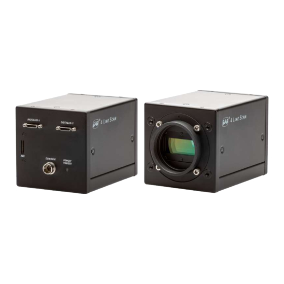
SW-4010Q-MCL-M52 User Manual (1.1) Parts Identification Parts Identification ① Lens Mount (M52-Mount) ② Digital I/O-1 and Digital I/O-2 Video Output Connectors ③ POWER/TRIG LED ④ DC IN/TRIG Connector (12-Pin Round) ⑤ AUX Connector (10-pin) ⑥ ⑦ Mounting Holes ① Lens Mount (M52-Mount) Mount the custom lens (JMO-M5231-2828-C4, sold separately) to the camera. - Page 16 SW-4010Q-MCL-M52 User Manual (1.1) Parts Identification Camera Link Connector 1 Input Signal Description Output 1, 26 Shield 2 (-), 15 (+) TxOUT0 Data output 3 (-), 16 (+) TxOUT1 Data output DIGITAL I/O - 1 4 (-), 17 (+) TxOUT2...
-
Page 17: ③ Power/Trig Led
SW-4010Q-MCL-M52 User Manual (1.1) Parts Identification ③ POWER/TRIG LED Indicates the power or trigger input status. Status Lit amber Camera initializing. Lit green Camera in operation During operation in trigger mode, trigger signals are being input. Blinking Note: The blinking interval is not related to the actual input interval of the green external trigger. - Page 18 SW-4010Q-MCL-M52 User Manual (1.1) Parts Identification TTL Signal specification Output voltage: Low 0.0V, High 5.0V TTL out signal specification (Typ.) Input/Output current: +/-32mA TTL in signal specification (Typ.) Input voltage: Low 0.0 ~ 0.8V, High 2.0 ~ 5.5V Caution: The DC IN / TRIG IN connector, AUX connector, or the CC1 of the DIGITAL I/O-1 video output connector will be used for external trigger inputs.
-
Page 19: ⑤ Aux Connector (10-Pin)
SW-4010Q-MCL-M52 User Manual (1.1) Parts Identification ⑤ AUX Connector (10-pin) Connect the cable for DC IN / trigger IN here. Camera side: Equivalent to Hirose Electronic 3260-10S3(55) Cable side: Equivalent to Hirose Electronic 3240-10P-C(50) Pin No. Attribute Name Description TTL OUT2... -
Page 20: Preparation
Save the current setting configurations in user memory. Short ASCII Commands The most universal method for controlling a Camera Link camera such as SW-4010Q-MCL-M52 is by the use of short ASCII commands sent via serial communications. All Camera Link frame grabber boards support the use of these short ASCII commands. -
Page 21: Step 1: Connect Devices
(Setting List). The SW-4010Q-MCL-M52 fully supports applications written using GenICam-based SDKs. The advantage of this is that programs written using GenICam names can be applied with little or no modification to control cameras with other GenICam-compliant interfaces and even GenICam- compliant cameras from different vendors. -
Page 22: ① Lens
SW-4010Q-MCL-M52 User Manual (1.1) Preparation ① Lens Attach the customized lens JMO-M5231-2828-C4 (sold separately) to the camera. This lens is for a prism camera and is optimized to match the camera's pixel size. Focal length: 28mm Spectral Range: 400 - 1700 nm Aperture: F2.8 - F22... -
Page 23: ② Mounting
SW-4010Q-MCL-M52 User Manual (1.1) Preparation ② Mounting When mounting the camera directly to a wall or other device, use screws that match the mounting holes on the camera (M4: depth 6mm). Caution: For heavy lenses, be sure to support the lens itself. Do not use configurations in which its weight is supported by the camera. -
Page 24: Step 2: Verify Camera Operation
SW-4010Q-MCL-M52 User Manual (1.1) Preparation Step 2: Verify Camera Operation When power is supplied to the camera while the necessary equipment is connected, the POWER/TRIG LED at the rear of the camera lights amber, and initialization of the camera starts. -
Page 25: Step 3: Verify The Connection Between The Camera And Pc
SW-4010Q-MCL-M52 User Manual (1.1) Preparation Step 3: Verify the Connection Between the Camera and PC Use a short ASCII command to verify whether the camera is properly recognized in your setup. 1. Install terminal emulator software capable of serial communication to the PC connected to the camera via the frame grabber board. -
Page 26: Step 4: Configure Basic Settings For The Camera
SW-4010Q-MCL-M52 User Manual (1.1) Preparation Step 4: Configure Basic Settings for the Camera Note: On this camera, you must configure both the RGB and SWIR channels individually. Configure the Camera Output Formats Configure the pixel formats of the image output from the RGB and SWIR channels. -
Page 27: Configure The Imagescalingmode Settings
SW-4010Q-MCL-M52 User Manual (1.1) Preparation Configure the ImageScalingMode Settings Notes: The SWIR channel does not support the ImageScalingMode function. For more information on this function, see Image Scaling Mode (Xscale). 1. To check the ImageScalingMode setting, enter the command ISM?<CR><LF> from the terminal emulator software. -
Page 28: Control Via External Triggers
SW-4010Q-MCL-M52 User Manual (1.1) Preparation Control via External Triggers When Controlling the Exposure Time Using Specified Exposure Times 1. First, configure the RGB channels. Set Exposure Mode to Timed. (Timed = Default). 2. Specify the Exposure Time in Exposure Time. For the RGB channels, you must configure each R, G, and B channel individually. -
Page 29: Step 5: Adjust The Image Quality
SW-4010Q-MCL-M52 User Manual (1.1) Preparation Step 5: Adjust the Image Quality Related Setting Items: AnalogControl To maximize the performance of the camera, configure its basic function in the following order. Note: On this camera, you must configure both the RGB and SWIR channels individually. -
Page 30: Dsnu Correction (Pixel Black Correct)
SW-4010Q-MCL-M52 User Manual (1.1) Preparation DSNU Correction (Pixel Black Correct) Related Setting Items: CorrectionControl, SWIRCorrectionControl DSNU (dark signal non-uniformity) is a variation between pixels in the dark areas generated by the sensor. If the line rate is slowed or a long exposure time is set, the dark current in the sensor may change and the state of the DSNU may change. -
Page 31: Prnu Correction (Pixel Gain Correct)
SW-4010Q-MCL-M52 User Manual (1.1) Preparation PRNU Correction (Pixel Gain Correct) Related Setting Items: CorrectionControl, SWIRCorrectionControl PRNU (photo response non-uniformity) is a variation between pixels generated by the sensor under bright conditions. If the line rate is slowed or a long exposure time is set, the dark current in the sensor may change and the state of the PRNU may change. -
Page 32: Adjust The Black Level
SW-4010Q-MCL-M52 User Manual (1.1) Preparation SWIR 1. Select User to save the gain correction value with SWIRPixelGainCorrect. Note: You cannot perform calibration when Off or Factory is selected. 2. Gain correction data is automatically generated by SWIRPixelGainCalibration and saved in the user area specified in step 1. -
Page 33: Step 6: Configure Various Other Settings
SW-4010Q-MCL-M52 User Manual (1.1) Preparation Step 6: Configure Various Other Settings “Setting List” or "Short ASCII Command List" to configure settings as necessary. Note: We recommend performing DSNU and PRNU calibration again whenever the line rate setting is changed significantly. Step 7: Save the Settings... -
Page 34: Save The User Settings
SW-4010Q-MCL-M52 User Manual (1.1) Preparation Save the User Settings 1. Stop image acquisition. Settings can only be saved when image acquisition on the camera is stopped. 2. Specify the storage location (UserSet1 - UserSet3) using the UserSetSave command and save the current camera settings. -
Page 35: Main Functions
SW-4010Q-MCL-M52 User Manual (1.1) Main Functions Main Functions This chapter describes the camera's main functions. Basic Function Matrix Related Setting Items: DigitalIOControl, AcquisitionControl, SWIRAcquisitionControl, PulseGenerator The following signals can be used as sources for each output destination (TriggerSelector, LineSelector, PulseGeneratorSelector). - Page 36 SW-4010Q-MCL-M52 User Manual (1.1) Main Functions Output Destination Trigger LineSelector PulseGeneratorSelector Pulse Pulse Pulse Pulse Source Signal (Cross Line Line 1 Line 8 Line9 Line12 NAND0 NAND1 Genera- Genera- Genera- Genera- Point Switch Point) Start TTLOut1 TTLOut2 TTLOut3 TTLOut4 tor 0...
-
Page 37: Gpio (Digital Input/Output Settings)
SW-4010Q-MCL-M52 User Manual (1.1) Main Functions GPIO (Digital Input/Output Settings) Related Setting Items: DigitalIOControl The camera can input/output the following signals to and from external input/output connectors. TTL OUT 1 (Line 1) DC IN / TRIG IN Connector (12-pin) TTL OUT 4 (Line 12) -
Page 38: Camera Output Formats
SW-4010Q-MCL-M52 User Manual (1.1) Main Functions For digital output, set the output source signal using LineSource. Set the source signal in the same way for NAND Logic (Nand0In1, Nand0In2, Nand1In1, Nand1In2). Note: For more information on the combinations of source signals and output destinations, Basic Function Matrix. - Page 39 SW-4010Q-MCL-M52 User Manual (1.1) Main Functions SWIR - 39 -...
-
Page 40: Camera Link Bit Assignments
SW-4010Q-MCL-M52 User Manual (1.1) Main Functions Camera Link Bit Assignments This camera conforms to the Camera Link standard. The bit assignments are as follows. Camera Link Connector 1 (RGB) RGB10BasePacked Port/Signal 8-bit (RGB8) Connector Pin Name RGB12BasePacked Port A0 R_D0... - Page 41 SW-4010Q-MCL-M52 User Manual (1.1) Main Functions Camera Link Connector 2 (SWIR) Port/Signal Mono8 Mono10/Mono12 Connector Pin Name Port A0 SWIR_D0 SWIR_D0 Port A1 SWIR_D1 SWIR_D1 Port A2 SWIR_D2 SWIR_D2 Port A3 SWIR_D3 SWIR_D3 Port A4 SWIR_D4 SWIR_D4 Port A5 SWIR_D5...
-
Page 42: Image Scaling Mode (Xscale)
SW-4010Q-MCL-M52 User Manual (1.1) Main Functions Image Scaling Mode (Xscale) Related Setting Items: ImageFormatControl This camera uses RGB and SWIR sensors with different pixel sizes, resolutions, and timing characteristics to acquire images. As a result, the default line rates and FOV of the RGB and SWIR channels are different. - Page 43 SW-4010Q-MCL-M52 User Manual (1.1) Main Functions How To Configure 1. Enable ImageScalingMode. The options are: On: Enables ImageScalingMode. SWIRPixelMode: Enables ImageScalingMode, and sets the RGB channels' PixelSize and Width to match the SWIR channel's Pixel Size and Width (PixelSize = 25um, Width = 1024).
-
Page 44: Swirpixelmode And Swirhalfpixelmode
SW-4010Q-MCL-M52 User Manual (1.1) Main Functions SWIRPixelMode and SWIRHalfPixelMode The SWIRPixelMode and SWIRHalfPixelMode options configure the RGB channels' PixelSize and Width settings to match the SWIR channel's PixelSize and Width settings, by automatically setting ImageScalingHorizontal and ImageScalingWidthMax. These options set the horizontal scaling ratio (ImageScalingHorizontal) to 0.3 or 0.6 to scale the PixelSize, and then cut off the ROI ... -
Page 45: Exposure Mode
SW-4010Q-MCL-M52 User Manual (1.1) Main Functions Note: The ImageScalingHorizontal values are calculated from the following formulas and they are not 0.3 or 0.6 exact. If you use a Control Tool, the following value will be displayed. SWIRPixelMode: ImageScalingHorizontal = ImageScalingHorizontalRaw/ImageScalingBaseAbs = 1228/4096 ≒ 0.2998 SWIRHalfPixelMode: ImageScalingHorizontal = ImageScalingHorizontalRaw/ImageScalingBaseAbs = 2456/4096 ≒... -
Page 46: Trigger Control
SW-4010Q-MCL-M52 User Manual (1.1) Main Functions Trigger Control Related Setting Items: AcquisitionControl, SWIRAcquisitionControl The camera allows Line Start trigger controls to be performed via external trigger signals. The Line Start trigger allows exposure control via the trigger signal inputs. Note: The settings for exposure control and triggers are related to each other. Be sure to... -
Page 47: Calculate The Max Line Rate (Rgb)
SW-4010Q-MCL-M52 User Manual (1.1) Main Functions Calculate the Max Line Rate (RGB) Related Setting Items: AcquisitionControl Notes: The SWIR channel has a fixed Width value (1024). Therefore, the maximum line rate is always 39.2kHz. The Line Rate Calculator, which calculates the maximum line rate, is available for download from the product page on the JAI website (www.jai.com). - Page 48 SW-4010Q-MCL-M52 User Manual (1.1) Main Functions LinePeriod[us] The formula for calculating the LinePeriod[us] value depends on the Camera Output Formats setting. A. PixelFormat = RGB8 LinePeriod[us] = Roundup(LineClock / CLWidth * 1000000 + Jitter, 2) B. PixelFormat = RGB10BasePacked / RGB12BasePacked LinePeriod[us] = Roundup(LineClock / (CLWidth*2/3) * 1000000 + Jitter, 2) Calculate the final LinePeriod value.
-
Page 49: Timing Chart
SW-4010Q-MCL-M52 User Manual (1.1) Main Functions Timing Chart Related Setting Items: AcquisitionControl, SWIRAcquisitionControl This section shows the timing charts under the following conditions. ExposureMode = Off, TriggerMode = Off ExposureMode = Timed, TriggerMode = Off ExposureMode = OFF, TriggerMode = ON... - Page 50 SW-4010Q-MCL-M52 User Manual (1.1) Main Functions RGB: Binning = ON (BinningHorizontal = 2) Period from Device Clock LVAL Period LVAL Low LVAL High Exposure PixelFormat Frequency Configuration [A](us) [B](us) [C](us) end to LVAL (MHz) start [D](us) 24.47 0.38 24.09 35.59 RGB8 31.98...
- Page 51 SW-4010Q-MCL-M52 User Manual (1.1) Main Functions SWIR Period from Device Clock LVAL Period LVAL Low LVAL High Exposure PixelFormat Frequency Configuration [A](us) [B](us) [C](us) end to LVAL (MHz) start [D](us) 25.5 13.45 12.05 48.67 Mono8 25.49 9.74 15.75 48.67 42.5 25.51...
-
Page 52: Exposuremode = Timed, Triggermode = Off
SW-4010Q-MCL-M52 User Manual (1.1) Main Functions ExposureMode = Timed, TriggerMode = Off RGB: Binning = OFF Period from Device Clock LVAL Period LVAL Low LVAL High Exposure PixelFormat Frequency Configuration [A](us) [B](us) [C](us) end to LVAL (MHz) start [D](us) 48.55 0.37... - Page 53 SW-4010Q-MCL-M52 User Manual (1.1) Main Functions RGB: Binning = ON (BinningHorizontal = 2) Period from Device Clock LVAL Period LVAL Low LVAL High Exposure PixelFormat Frequency Configuration [A](us) [B](us) [C](us) end to LVAL (MHz) start [D](us) 24.47 0.38 24.09 30.65 RGB8 31.97...
- Page 54 SW-4010Q-MCL-M52 User Manual (1.1) Main Functions SWIR Period from Device Clock LVAL Period LVAL Low LVAL High Exposure PixelFormat Frequency Configuration [A](us) [B](us) [C](us) end to LVAL (MHz) start [D](us) 25.51 13.46 12.04 23.28 Mono8 25.51 9.76 15.75 23.28 42.5 25.51...
-
Page 55: Exposuremode = Off, Triggermode = On
SW-4010Q-MCL-M52 User Manual (1.1) Main Functions ExposureMode = OFF, TriggerMode = ON RGB: Binning = OFF Period from Period Device Trigger from Trigger Exposure LVAL Clock Start edge Exposure PixelFormat Period [A] Time [C] Period [E] Configuration Frequency end to... - Page 56 SW-4010Q-MCL-M52 User Manual (1.1) Main Functions RGB: Binning = ON (BinningHorizontal = 2) Period from Period Device Trigger from Trigger Exposure LVAL Clock Start edge Exposure PixelFormat Period [A] Time [C] Period [E] Configuration Frequency end to (us) (us) (us)
- Page 57 SW-4010Q-MCL-M52 User Manual (1.1) Main Functions SWIR Period from Period Device Trigger from Trigger Exposure LVAL Clock Start edge Exposure PixelFormat Period [A] Time [C] Period [E] Configuration Frequency end to (us) (us) (us) (MHz) Exposure LVAL start start [B]...
-
Page 58: Exposuremode = Timed, Triggermode = On
SW-4010Q-MCL-M52 User Manual (1.1) Main Functions ExposureMode = Timed, TriggerMode = ON RGB: Binning = OFF Period from Period Device Trigger from Trigger Exposure LVAL Clock Start edge Exposure PixelFormat Period [A] Time [C] Period [E] Configuration Frequency end to... - Page 59 SW-4010Q-MCL-M52 User Manual (1.1) Main Functions RGB: Binning = ON (BinningHorizontal = 2) Period from Period Device Trigger from Trigger Exposure LVAL Clock Start edge Exposure PixelFormat Period [A] Time [C] Period [E] Configuration Frequency end to (us) (us) (us)
- Page 60 SW-4010Q-MCL-M52 User Manual (1.1) Main Functions SWIR Period from Period Device Trigger from Trigger Exposure LVAL Clock Start edge Exposure PixelFormat Period [A] Time [C] Period [E] Configuration Frequency end to (us) (us) (us) (MHz) Exposure LVAL start start [B]...
-
Page 61: Pixel Sensitivity Correction
SW-4010Q-MCL-M52 User Manual (1.1) Main Functions Pixel Sensitivity Correction Related Topic: CorrectionControl, SWIRCorrectionControl Correct variations between the sensor’s pixels. Calibration must be performed within the camera and correction data must be created beforehand. DSNU (PixelBlackCorrect) / PRNU (PixelGainCorrect) can be reduced using that correction data. -
Page 62: Defective Pixel Correction
SW-4010Q-MCL-M52 User Manual (1.1) Main Functions Defective Pixel Correction Related Setting Items: SWIRBlemishControl Correct defective pixels. Correction is performed using the average value between the pixels to the immediate left and right. Up to eight defective pixels can be corrected. The pixels at the left and right edges cannot be corrected. -
Page 63: Gain Control (Rgb Channels)
SW-4010Q-MCL-M52 User Manual (1.1) Main Functions Gain Control (RGB Channels) Related Setting Items: AnalogControl The following gain functions are available on the camera: Analog Base Gain and Digital Gain (MasterMode, IndividualMode) Analog Base Gain Analog base gain (ABG) is gain that is performed to the analog video signal output from the sensor. -
Page 64: Gain Control (Swir Channel)
SW-4010Q-MCL-M52 User Manual (1.1) Main Functions Gain Control (SWIR Channel) Related Setting Items: SWIRAnalogControl The following three gain functions are available on the camera: Sensor Conversion Gain, Analog Base Gain, and Analog Fine Gain. Sensor Conversion Gain Sensor conversion gain (SCG) is InGaAs sensors' internal gain. Settings configured individually from an external source, and the amount of gain can be adjusted via different combinations of 3- bit setting values. -
Page 65: Gamma Function
SW-4010Q-MCL-M52 User Manual (1.1) Main Functions Analog Fine Gain Analog fine gain (AFG) is gain that is performed after the video signal passes through the CDS circuit and prior to ADC (analog digital conversion). The setting range is 0 ~ +11dB (0 ~ 308). -
Page 66: To Use The Gamma Function
SW-4010Q-MCL-M52 User Manual (1.1) Main Functions To Use the Gamma Function Configure the settings as follows. Item Setting Value / Selectable Range Description Gamma 0.45, 0.5, 0.55, 0.6, 0.65, 0.75, 0.8, 0.9, 1.0 Select the Gamma correction value. LUTMode Gamma Use Gamma. -
Page 67: Lut (Lookup Table)
SW-4010Q-MCL-M52 User Manual (1.1) Main Functions LUT (Lookup Table) Related Setting Items: LUTControl The LUT function is used to generate a non-linear mapping between signal values captured on the sensor and those that are output from the camera. On this camera, you can specify the output curve using 257 setting points (indexes) for the RGB channels and 256 setting points (indexes) -
Page 68: Lut Value
SW-4010Q-MCL-M52 User Manual (1.1) Main Functions LUT Value LUT values range from 0 at the lowest to 4095 at the highest. Linear interpolation is used to calculate LUT values between the index points. - 68 -... -
Page 69: Shading Correction
SW-4010Q-MCL-M52 User Manual (1.1) Main Functions Shading Correction Related Setting Items: ShadingControl, SWIRShadingControl The ShadingCorrection function corrects non-uniformity (i.e., shading) in the amount of light generated by the lens and lighting equipment. The following shading correction modes are available on the camera. -
Page 70: To Use The Shading Correction Function
SW-4010Q-MCL-M52 User Manual (1.1) Main Functions To Use the Shading Correction Function The function is turned ON/OFF via serial communication. This function is not dependent on the operation mode but is effective when used during actual use. Note: You can save the setting, and have it applied whenever the power is subsequently turned on. -
Page 71: Variable Line Rate
SW-4010Q-MCL-M52 User Manual (1.1) Main Functions Variable Line Rate Related Setting Items: AcquisitionControl, SWIRAcquisitionControl You can set the line rate to 1L or more. This function can be used to match the scanning speed of the camera to the feeding speed of the object or to lengthen the accumulation time to increase sensitivity. -
Page 72: Number Of Pixels Per Line And Line Rate (Rgb)
SW-4010Q-MCL-M52 User Manual (1.1) Main Functions Number of Pixels per Line and Line Rate (RGB) You can increase the line rate by decreasing the number of pixels per line on the RGB channels. Use Width (ASCII = WTC) to set the line width. The line rate can be increased to a maximum of 183.4 kHz for each configuration. -
Page 73: Electronic Shutter
SW-4010Q-MCL-M52 User Manual (1.1) Main Functions Electronic Shutter Related Setting Items: AcquisitionControl, SWIRAcquisitionControl How to Compensate Lateral Chromatic Aberration When you use this function, you can set the exposure to a preconfigured accumulation time, regardless of the line rate. SWIR Variable Range 3 μs ~ 15149.07 μs... -
Page 74: Exposureactive Function
SW-4010Q-MCL-M52 User Manual (1.1) Main Functions ExposureActive Function Related Setting Items: AcquisitionControl, SWIRAcquisitionControl Perform external output for the timing at which video is accumulated to the sensor. The signal is output to the DC IN / TRIG IN connector (12-pin round) and the DIGITAL I/O-1 video output connector (Camera Link). -
Page 75: Color Space Conversion (Color Transformation Control)
SW-4010Q-MCL-M52 User Manual (1.1) Main Functions Color Space Conversion (Color Transformation Control) Related Setting Items: ColorTransformationControl This camera allows you to convert the standard color space (RGB) that is used to produce colors into other color spaces, including XYZ and HSI. Five color spaces are available: RGB(sRGB), RGB(AdobeRGB), RGB(UserCustom), XYZ, and HSI. - Page 76 SW-4010Q-MCL-M52 User Manual (1.1) Main Functions Notes: About Color Space HSI Hue Value: 0° to 360° can be specified as follows. 8bit output: Can be specified in 2° increments - 0°(00000000) ~ 360°(10110100) 10bit output: Can be specified in 0.5°increments- 0°(0000000000) ~ 360°(1011010000) 12bit output: Can be specified in 0.5°increments- 0°(000000000000) ~ 360°...
-
Page 77: Counter And Timer Control Function
SW-4010Q-MCL-M52 User Manual (1.1) Main Functions Counter and Timer Control Function Related Setting Items: CounterAndTimerControl Note: This camera supports only the counter function. The counter function counts up change points in the camera’s internal signals using the camera’s internal counter and reads that information from the host side. This function is useful for verifying error conditions via the count value using internal camera operations. -
Page 78: Counter Occurrence Diagram
SW-4010Q-MCL-M52 User Manual (1.1) Main Functions Counter Occurrence Diagram Note: You can reset a specific counter's count value by executing CounterReset[Counter0 ~ Internal Camera Blocks - 78 -... -
Page 79: To Use The Counter Function
SW-4010Q-MCL-M52 User Manual (1.1) Main Functions To Use the Counter Function Configure the settings as follows. Eight counters are available. Specify a counter (Counter0 to Counter7), and configure the settings. Setting Value Item Description Selectable Range Counter 0 ~ 7 Counter 0 ~ 7 Select the counter. -
Page 80: Chromatic Aberration Correction
SW-4010Q-MCL-M52 User Manual (1.1) Main Functions Chromatic Aberration Correction Related Setting Items: CorrectionControl This function corrects for the chromatic aberration of magnification caused by the lens (i.e., when the size of the image differs at the focal point for each color (RGB)). You can save correction data for three types of lenses. -
Page 81: Connecting Rotary Encoders
SW-4010Q-MCL-M52 User Manual (1.1) Main Functions Connecting Rotary Encoders Related Setting Items: EncoderControl This camera can generate trigger signals or detect the scanning direction of the subject in response to signals output from the rotary encoder. Adjustment Procedure 1. Input the two signals (phase A and phase B) from the rotary encoder. Select which I/O on... -
Page 82: Noise Reduction Filter Functions
SW-4010Q-MCL-M52 User Manual (1.1) Main Functions Noise Reduction Filter Functions Related Setting Items: CorrectionControl, SWIRCorrectionControl The camera has noise reduction functions. The noise reduction methods vary depending on the channel. Three filters are available for the RGB channels: MEDIAN Filter: Apply 1x3 MEDIAN filter Select the target to apply the filter from Red, Green, Blue, and set the Median Filter Mode. -
Page 83: Setting List
SW-4010Q-MCL-M52 User Manual (1.1) Setting List Setting List This camera complies with GenICam. Each setting item name conforms to GenICam SFNC (Standard Features Naming Convention). (There are some JAI-specific setting items). Each setting item is an integer type (IInteger), a real type (IFloat), an element enumeration type (IEnumeration), a character string (IString), a logical type (IBoolean), and a category type (ICategory) or a command type (ICommand) for executing the function. -
Page 84: Feature Properties
SW-4010Q-MCL-M52 User Manual (1.1) Setting List Feature Properties Note: Depending on the setting item, you may need to change visibility. Please switch visibility (Beginner / Expert / Guru) as necessary. DeviceControl Display/configure information related to the device. Setting DeviceControl Item... - Page 85 SW-4010Q-MCL-M52 User Manual (1.1) Setting List Setting DeviceControl Item Default Value Description Range 0: Main board Select the area of the camera's interior where the temperature DeviceTemperatureSelector is to be measured. SWIR Sensor Display the internal temperature (°C) of the device specified by...
-
Page 86: Imageformatcontrol
SW-4010Q-MCL-M52 User Manual (1.1) Setting List ImageFormatControl Configure image format settings for the RGB channels. Setting Default Image Format Control Item Description Range Value Display the maximum image width. Default: 4096 ImageScalingMode = Off : WidthMax 4096 - BinningHorizontal=1: 4096, BinningHorizontal=2: 2048... - Page 87 SW-4010Q-MCL-M52 User Manual (1.1) Setting List Setting Default Image Format Control Item Description Range Value Display the horizontal scaling ratio defined based on the ImageScalingHorizontalRaw setting in decimal units. For example, if the image is scaled by 50% in the horizontal direction, ImageScalingHorizontal 0.0625 ~ 1...
-
Page 88: Acquisitioncontrol
SW-4010Q-MCL-M52 User Manual (1.1) Setting List AcquisitionControl Configure image capture settings for the RGB channels. Acquisition Control Item Setting Range Default Value Description Set the AcquisitionLineRate(Hz). AcquisitionLineRate (Hz) Min: 500 Max: Related Topic: - Width = 4096: (RGB8) 20.5kHz, (RGB10/12) 13.7kHz Variable Line Rate - Width = 2048: (RGB8) 40.8kHz, (RGB10/12) 27.3kHz... - Page 89 SW-4010Q-MCL-M52 User Manual (1.1) Setting List Acquisition Control Item Setting Range Default Value Description Specify the sensor for which to set the ExposureTime. Select Common if ExposureTimeMode is set to Common. Select 0: Common Red/Green/Blue if ExposureTimeMode is set to Individual.
-
Page 90: Analogcontrol
SW-4010Q-MCL-M52 User Manual (1.1) Setting List AnalogControl Configure the analog control settings for the RGB channels. Default Analog Control Item Setting Range Description Value IndividualGainMode 0:Off In IndividualGainMode, RGB can be configured individually for the entire Related Topic: 0:Off gain adjustment range of the sensor. - Page 91 SW-4010Q-MCL-M52 User Manual (1.1) Setting List Default Analog Control Item Setting Range Description Value BlackLevelSelector 0: DigitalAll Related Topic: 1: DigitalRed 0: All Select the black level to configure. Adjust the Black 2: DigitalBlue Level Set the black level value.
-
Page 92: Lutcontrol
SW-4010Q-MCL-M52 User Manual (1.1) Setting List Default Analog Control Item Setting Range Description Value When BalanceWhiteAuto is set to ExposureOnce, display the status. 1:Succeeded AWBExposureOnce 2:Error1- G image was too bright 5:Idle Status 3:Error2 - G image was too dark... -
Page 93: Colortransformationcontrol
SW-4010Q-MCL-M52 User Manual (1.1) Setting List ColorTransformationControl Configure color transformation settings. Related Topic: Color Space Conversion (Color Transformation Control) Color Transformation Control Setting Default Description Item Range Value 0:RGB ColorTransformationMode 1: HSI 0:RGB Set the output image format. 2: XYZ... -
Page 94: Digitaliocontrol
SW-4010Q-MCL-M52 User Manual (1.1) Setting List DigitalIOControl Configure settings for digital input/output. Related Topic: GPIO (Digital Input/Output Settings) Setting Default Digital IO Control Item Description Range Value Select the input/output to configure. 0: Line1 TTL Out1(12-pin) 3: Line4 TTL In1 (12-pin) - Page 95 SW-4010Q-MCL-M52 User Manual (1.1) Setting List Setting Default Digital IO Control Item Description Range Value Select the line source signal for the item selected in LineSelector. 0: Low 1: High 7: ExposureActive 9: LVAL 10: PulseGenerator0 11: PulseGenerator1 12: PulseGenerator2...
- Page 96 SW-4010Q-MCL-M52 User Manual (1.1) Setting List Setting Default Digital IO Control Item Description Range Value Display the input/output signal status. bit0:Line1 (TTL Out1) bit1 - 2:Unused (fixed 0) bit3:Line4 (TTL In1) bit4:Line5 (Opt In1) bit5 - 6:Unused (fixed 0) bit0:Line1...
-
Page 97: Counterandtimercontrol
SW-4010Q-MCL-M52 User Manual (1.1) Setting List CounterAndTimerControl Configure counter settings. Note: This camera only supports the counter functions. Related Topic: Counter and Timer Control Function CounterAndTimer Setting Range Default Value Description Control Item Select the counter. CounterSelector 0: Counter0 0 - 7: Counter0 - 7... -
Page 98: Encodercontrol
SW-4010Q-MCL-M52 User Manual (1.1) Setting List CounterAndTimer Setting Range Default Value Description Control Item 0: CounterIdle 2: CounterActive 4: CounterOverflow CounterStatus 0: CounterIdle Display the counter status. - Count value exceedded the maximum value. EncoderControl Configure the rotary encoder related settings. -
Page 99: Usersetcontrol
SW-4010Q-MCL-M52 User Manual (1.1) Setting List Setting Default Encoder Control Item Description Range Value Enables external setting of the upper limit of the internal frequency calculation result so that the period of the output frequency is no longer than the user-specified period. -
Page 100: Transportlayercontrol
SW-4010Q-MCL-M52 User Manual (1.1) Setting List TransportLayerControl Display information on transport layer control for the RGB channels. Setting Default Transport Layer Control Item Description Range Value Display the transfer method (tap configuration) of images transferred from the camera at one time. -
Page 101: Pulsegenerator
SW-4010Q-MCL-M52 User Manual (1.1) Setting List PulseGenerator Configure pulse generator settings. Pulse Generator Item Setting Range Default Value Description Set the division value for the prescaler (12 bit) using ClockPreScaler 1 ~ 4096 PixelClock as the base clock. Set the clock used for the pulse generator. This value... - Page 102 SW-4010Q-MCL-M52 User Manual (1.1) Setting List Pulse Generator Item Setting Range Default Value Description Set the start point of the Low interval in milliseconds. When the counter reaches this value, the output will be 0. The setting range varies depending on the PulseGeneratorEndPointMs 0.15...
-
Page 103: Shadingcontrol
SW-4010Q-MCL-M52 User Manual (1.1) Setting List ShadingControl Configure shading correction settings for the RGB channels. Related Topic: Shading Correction Default Shading Control Item Setting Range Description Value Select the shading correction method. 0: Flat ShadingCorrectionMode 0: Flat Shading Shading 1: Color Shading 0: Off Set the area to which to save shading correction data. -
Page 104: Correctioncontrol
SW-4010Q-MCL-M52 User Manual (1.1) Setting List CorrectionControl Configure settings related to the correction function for nonuniformity in black levels and gain between pixels (RGB channels -PRNU/DSNU). Setting Default Correction Control Item Description Range Value 0: Off PixelBlackCorrectionMode (DSNU) Select the user area to which to save the black 1: Default level correction value. - Page 105 SW-4010Q-MCL-M52 User Manual (1.1) Setting List Setting Default Correction Control Item Description Range Value ChromaticAberration 0: Off CorrectionMode 1:Lens1 Correct the color aberration that occurs at the left and 0: Off right edges due to lens characteristics. 2:Lens2 Related Topic:...
-
Page 106: Swirimageformatcontrol
SW-4010Q-MCL-M52 User Manual (1.1) Setting List SWIRImageFormatControl Configure image format settings for the SWIR channel. SWIR Image Format Control Item Setting Range Default Value Description SWIRWidth 1024 (fixed) Display the image width. SWIRPixelFormat 0: Mono8 1: Mono10 0: Mono8 Set the pixel format. - Page 107 SW-4010Q-MCL-M52 User Manual (1.1) Setting List Default SWIR Acquisition Item Setting Range Description Value SWIRAcquisitionLineRate (Hz) 500.012 ~ 39215 Specify the line rate (Hz). 39215 Related Topic: Variable Line Rate SWIRExposureMode 0: Off 1: Timed Select the exposure mode. Related Topic:...
-
Page 108: Swiranalogcontrol
SW-4010Q-MCL-M52 User Manual (1.1) Setting List SWIRAnalogControl Configure the analog control settings for the SWIR channel. Setting SWIR Analog Control Item Default Value Description Range SWIRSensOutCfa 0: Zero 1: One Set the sensor’s internal conversion gain. Related Topic: Gain Control... -
Page 109: Swirlutcontrol
SW-4010Q-MCL-M52 User Manual (1.1) Setting List SWIRLUTControl Configure LUT settings for the SWIR channel. Related Topic: LUT (Lookup Table) SWIR Lut Control Item Setting Range Default Value Description SWIRLUTSelector 0: Luminance (fixed) Display the LUT channel to control. SWIRLUTIndex 0 ~ 255 Set the LUT index table number. -
Page 110: Swirshadingcontrol
SW-4010Q-MCL-M52 User Manual (1.1) Setting List SWIRShadingControl Configure shading correction settings for the SWIR channel. Related Topic: Shading Correction Setting SWIR Shading Control Item Default Value Description Range Set the area to which to save shading correction data. When this is set to Off, SWIRShadingCalibration will not 0: Off be executed. -
Page 111: Swircorrectioncontrol
SW-4010Q-MCL-M52 User Manual (1.1) Setting List SWIRCorrectionControl Configure settings related to the correction function for nonuniformity in black levels and gain between pixels for the SWIR channel. Setting SWIR Correction Control Item Default Value Description Range SWIRPixelBlackCorrect (DSNU) Select the area to which to save the 0: Off pixel black correction value. -
Page 112: Swirblemishcontrol
SW-4010Q-MCL-M52 User Manual (1.1) Setting List SWIRBlemishControl Configure settings for JAI white blemish correction for the SWIR channel. Related Topic: Defective Pixel Correction Setting Default SWIR Blemish Control Item Description Range Value 0: Off SWIRBlemishCorrect 0: Off Enable/disable blemish correction. -
Page 113: Short Ascii Command List
SW-4010Q-MCL-M52 User Manual (1.1) Short ASCII Command List Short ASCII Command List All configuration of the camera is done via the RS-232C port. The camera can be set up from a PC running terminal emulator software. Below is the description of the ASCII based short command protocol. -
Page 114: Device Control (Command List)
SW-4010Q-MCL-M52 User Manual (1.1) Short ASCII Command List Switching baud rate between PC and camera Camera always starts up with 9600bps. This can be switched to higher baud rates after a communication has been established. When switching to other baud rate the procedure is as follows. - Page 115 SW-4010Q-MCL-M52 User Manual (1.1) Short ASCII Command List Short Default Device Control Name Access Values Example / Description ASCII Value UD=[Param.]<CR><LF> User can save and UD?<CR><LF> DeviceUserID load free text. (64 or less characters) Set the user ID for the camera CRS00<CR><LF>...
-
Page 116: Image Format Control (Rgb - Command List)
SW-4010Q-MCL-M52 User Manual (1.1) Short ASCII Command List Image Format Control (RGB - Command List) Configure image format settings for the RGB channels. Note: Descriptions of each command can also be found in "ImageFormatControl" (Setting List). Image Format Control Short Default Access... - Page 117 SW-4010Q-MCL-M52 User Manual (1.1) Short ASCII Command List Image Format Control Short Default Access Values Example / Description (RGB) Name ASCII Value ISSM=[Param.]<CR><LF> ISSM?<CR><LF> 0: Off (Average) ImageScalingSumMode ISSM Select whether to use Sum or 1: On (Sum) Average mode when ImageScalingMode is On.
-
Page 118: Acquisition Control (Rgb - Command List)
SW-4010Q-MCL-M52 User Manual (1.1) Short ASCII Command List Acquisition Control (RGB - Command List) Configure image capture settings for the RGB channels. Note: Descriptions of each command can also be found in "AcquisitionControl" (Setting List). Acquisition Control (RGB) Short Default Access Values Example / Description... - Page 119 SW-4010Q-MCL-M52 User Manual (1.1) Short ASCII Command List Acquisition Control (RGB) Short Default Access Values Example / Description Name ASCII Value TR=[Param.]<CR><LF> TR?<CR><LF> Select the exposure mode. 0:Off ExposureMode 1:Timed Note: When set to Timed, the exposure offset duration will be -0.85 μs.
-
Page 120: Analog Control (Rgb - Command List)
SW-4010Q-MCL-M52 User Manual (1.1) Short ASCII Command List Acquisition Control (RGB) Short Default Access Values Example / Description Name ASCII Value 300 ~ 1514907 PEMAX?<CR><LF> ExposureTimeUnit10nsMax PEMAX Unit: 10ns (100 = 1us) Display the maximum exposure time. EI=[Param.]<CR><LF> EI?<CR><LF> 0:Off RBExposureInterlocked Adjust exposure time of the R and B channels... - Page 121 SW-4010Q-MCL-M52 User Manual (1.1) Short ASCII Command List Analog Control Short Default Access Values Example / Description (RGB) Name ASCII Value AGC=[Param.]<CR><LF> AGC?<CR><LF> 0:Off GainAuto Enable/disable gain auto adjustment. Once 1:Once automatically changes to Off when the signal level converges once. AGCF=[Param.]<CR><LF>...
- Page 122 SW-4010Q-MCL-M52 User Manual (1.1) Short ASCII Command List Analog Control Short Default Access Values Example / Description (RGB) Name ASCII Value AWB=[Param.]<CR><LF> AWB?<CR><LF> 0:Off (Default) Set BalanceWhiteAuto. When set to Once, the 2:Once automatic adjustment will be performed only 4:Exposure Once BalanceWhiteAuto once, and then automatically switched to Off.
-
Page 123: Lut Control (Rgb - Command List)
SW-4010Q-MCL-M52 User Manual (1.1) Short ASCII Command List LUT Control (RGB - Command List) Configure LUT settings for the RGB channels. Note: Descriptions of each command can also be found in "LUTControl" (Setting List). Lut Control (RGB) Short Default Access Values Example / Description... -
Page 124: Color Transformation Control (Command List)
SW-4010Q-MCL-M52 User Manual (1.1) Short ASCII Command List Color Transformation Control (Command List) Configure color transformation settings. Note: Descriptions of each command can also be found in "ColorTransformationControl" (Setting List). Color Transformation Short Default Access Values Example / Description Control Name ASCII Value CTM=[Param.]<CR><LF>... - Page 125 SW-4010Q-MCL-M52 User Manual (1.1) Short ASCII Command List Color Transformation Short Default Access Values Example / Description Control Name ASCII Value CMVGR=[Param.]<CR><LF> CMVGR?<CR><LF> Specify the ColorMatrix value. -20000 ~ 20000 ColorMatrixValueInt [G-R] CMVGR ColorTransformationMode = RGB Step: 1000 ColorTransformationRGBMode=UserCustom Individually adjust 9 elements of the 3x3 color matrix (G-R) CMVGG=[Param.]<CR><LF>...
-
Page 126: Digital Io Control (Command List)
SW-4010Q-MCL-M52 User Manual (1.1) Short ASCII Command List Color Transformation Short Default Access Values Example / Description Control Name ASCII Value CMVBB=[Param.]<CR><LF> CMVBB?<CR><LF> Specify the ColorMatrix value. -20000 ~ 20000 ColorMatrixValueInt [B-B] CMVBB 1000 ColorTransformationMode = RGB Step: 1000 ColorTransformationRGBMode=UserCustom Individually adjust 9 elements of the 3x3 color... - Page 127 SW-4010Q-MCL-M52 User Manual (1.1) Short ASCII Command List Digital IO Control Short Default Access Values Example / Description Name ASCII Value ND0INV2=[Param.]<CR><LF> ND0INV2?<CR><LF> 0: False LineInverter ND0INV2 [NANDGate0In2] 1: True Invert the polarity of the signal (NANDGate0In1). ND1INV1=[Param.]<CR><LF> ND1INV1?<CR><LF> 0: False LineInverter...
- Page 128 SW-4010Q-MCL-M52 User Manual (1.1) Short ASCII Command List Digital IO Control Short Default Access Values Example / Description Name ASCII Value ND0IN1=[Param.]<CR><LF> ND0IN1?<CR><LF> LineSource ND0IN1 Same as LS0 [NANDGate0In1] Select signal to be passed to the Line NANDGate0In1. ND0IN2 =[Param.]<CR><LF> ND0IN2?<CR><LF> LineSource...
-
Page 129: Counter And Timer Control (Command List)
SW-4010Q-MCL-M52 User Manual (1.1) Short ASCII Command List Counter and Timer Control (Command List) Configure counter settings. Notes: This camera only supports the counter functions. Descriptions of each command can also be found in "CounterAndTimerControl" (Setting List). Counter and Timer Short Default... - Page 130 SW-4010Q-MCL-M52 User Manual (1.1) Short ASCII Command List Counter and Timer Short Default Access Values Example / Description Control Name ASCII Value CE7=[Param.]<CR><LF> CE7?<CR><LF> 0: Off (Stop the counter) CounterEventSource [Counter7] 1: SWIR Line Transfer End Select the events that will be the source to increment the Counter.
- Page 131 SW-4010Q-MCL-M52 User Manual (1.1) Short ASCII Command List Counter and Timer Short Default Access Values Example / Description Control Name ASCII Value CRS2=[Param.]<CR><LF> 0: Software CRS2?<CR><LF> 3: Line4 TTL In1 CounterResetSource CRS2 4: Line5 Opt In1 Select the reset source for the Counter2.
- Page 132 SW-4010Q-MCL-M52 User Manual (1.1) Short ASCII Command List Counter and Timer Short Default Access Values Example / Description Control Name ASCII Value 1: Rising Edge CRA2=[Param.]<CR><LF> CounterResetActivation 2: Falling Edge CRA2?<CR><LF> CRA2 [Counter2] 3: Level High Selects the timing for resetting Counter2.
- Page 133 SW-4010Q-MCL-M52 User Manual (1.1) Short ASCII Command List Counter and Timer Short Default Access Values Example / Description Control Name ASCII Value CR2<CR><LF> Reset the Counter2. CounterReset [Counter2] Note: This command can be used only when CounterResetSource is set to Software. CR3<CR><LF>...
- Page 134 SW-4010Q-MCL-M52 User Manual (1.1) Short ASCII Command List Counter and Timer Short Default Access Values Example / Description Control Name ASCII Value CV3?<CR><LF> CounterValue [Counter3] CV3 0 ~ 32bit max Display the Counter3's value. CV4?<CR><LF> CounterValue [Counter4] CV4 0 ~ 32bit max Display the Counter4's value.
-
Page 135: Encoder Control (Command List)
SW-4010Q-MCL-M52 User Manual (1.1) Short ASCII Command List Encoder Control (Command List) Configure Encoder settings. Note: Descriptions of each command can also be found in "EncoderControl" (Setting List). Short Default Encoder Control Name Access Values Example / Description ASCII Value ENCSA=[Param.]<CR><LF> 0: Line5 Opt In1 ENCSA?<CR><LF>... -
Page 136: User Set Control (Command List)
SW-4010Q-MCL-M52 User Manual (1.1) Short ASCII Command List Short Default Encoder Control Name Access Values Example / Description ASCII Value 0: none (no max) 1: 1 sec max NDEIM=[Param.]<CR><LF> 2: 2 sec max NDEIM?<CR><LF> 3: 3 sec max Enables external setting of the... -
Page 137: Transport Layer Control (Rgb - Command List)
SW-4010Q-MCL-M52 User Manual (1.1) Short ASCII Command List Transport Layer Control (RGB - Command List) Display information on transport layer control for the RGB channels. Note: Descriptions of each command can also be found in "TransportLayerControl" (Setting List). Transport Layer Control Short Default... -
Page 138: Pulse Generator (Command List)
SW-4010Q-MCL-M52 User Manual (1.1) Short ASCII Command List Pulse Generator (Command List) Configure pulse generator settings. Note: Descriptions of each command can also be found in "PulseGenerator" (Setting List). Short Default Pulse Generator Name Access Values Example / Description ASCII Value PGDEV=[Param.]<CR><LF>... - Page 139 SW-4010Q-MCL-M52 User Manual (1.1) Short ASCII Command List Short Default Pulse Generator Name Access Values Example / Description ASCII Value PGST1=[Param.]<CR><LF> PGST1?<CR><LF> Set the start point of the High PulseGeneratorStartPoint PGST1 0 ~ 1048575 interval as a clock count for [PulseGenerator1] PulseGenerator1. When the counter reaches this value, the output will be 1.
- Page 140 SW-4010Q-MCL-M52 User Manual (1.1) Short ASCII Command List Short Default Pulse Generator Name Access Values Example / Description ASCII Value PGEN3=[Param.]<CR><LF> PGEN3?<CR><LF> Set the start point of the Low PulseGeneratorEndPoint PGEN3 1 ~ 1048575 15000 interval as a clock count for [PulseGenerator3] PulseGenerator3.
- Page 141 SW-4010Q-MCL-M52 User Manual (1.1) Short ASCII Command List Short Default Pulse Generator Name Access Values Example / Description ASCII Value PGCM1 =[Param.]<CR><LF> 0: Off PGCM1 ?<CR><LF> 1: Level High PulseGeneratorClearActivation PGCM1 2: Level Low Set the clear signal condition for [PulseGenerator1] 4: Rising Edge...
- Page 142 SW-4010Q-MCL-M52 User Manual (1.1) Short ASCII Command List Short Default Pulse Generator Name Access Values Example / Description ASCII Value Same as PGIN0 PGIN2=[Param.]<CR><LF> PGIN2?<CR><LF> PulseGeneratorClearSource PGIN2 Note: 12: [PulseGenerator2] PulseGenerator2 cannot Select the count clear input signal be selected. source for PulseGenerator2.
-
Page 143: Shading Control (Rgb - Command List)
SW-4010Q-MCL-M52 User Manual (1.1) Short ASCII Command List Short Default Pulse Generator Name Access Values Example / Description ASCII Value PGSM2=[Param.]<CR><LF> PGSM2?<CR><LF> 0:Async Mode PulseGeneratorClearSyncMode PGSM2 [PulseGenerator2] 1:Sync Mode Selects the sync mode of the input to clear PulseGenerator2. PGSM3=[Param.]<CR><LF> PGSM3?<CR><LF> 0:Async Mode... - Page 144 SW-4010Q-MCL-M52 User Manual (1.1) Short ASCII Command List Short Default Shading Control Name Access Values Example / Description ASCII Value SDDS=[Param.]<CR><LF> 0: Green SDDS?<CR><LF> ShadingDataSelector SDDS 1: Red Read the shading correction data, and set 2: Blue the target sensor for modification.
-
Page 145: Correction Control (Rgb - Command List)
SW-4010Q-MCL-M52 User Manual (1.1) Short ASCII Command List Correction Control (RGB - Command List) Configure settings related to the correction function for nonuniformity in black levels and gain between pixels for the RGB channels. Note: Descriptions of each command can also be found in "CorrectionControl" (Setting List). - Page 146 SW-4010Q-MCL-M52 User Manual (1.1) Short ASCII Command List Short Default Correction Control Name (RGB) Access Values Example / Description ASCII Value 1: Succeeded PGS?<CR><LF> 2: Image too bright (PRNU) Display the results of PixelGainDetectResult 3: Image too dark PerformPixelGainCalibration 4: Timeout error execution.
- Page 147 SW-4010Q-MCL-M52 User Manual (1.1) Short ASCII Command List Short Default Correction Control Name (RGB) Access Values Example / Description ASCII Value FFG=[Param.]<CR><LF> FFG?<CR><LF> 0: Off FIRFilterMode [Green] 1: On Enable / Disable FIR Filter for Green. FFB=[Param.]<CR><LF> 0: Off FFB?<CR><LF> FIRFilterMode [Blue] 1: On Enable / Disable FIR Filter for Blue.
- Page 148 SW-4010Q-MCL-M52 User Manual (1.1) Short ASCII Command List Short Default Correction Control Name (RGB) Access Values Example / Description ASCII Value FFRRG=[Param.]<CR><LF> FFRRG?<CR><LF> FFRRG FIRFilterRightRatioInt [Green] -200 ~ 200 Set the coefficient of the right pixel when FIR Filter for Green is applied.
-
Page 149: Swir Image Format Control (Command List)
SW-4010Q-MCL-M52 User Manual (1.1) Short ASCII Command List SWIR Image Format Control (Command List) Configure image format settings for the SWIR channel. Note: Descriptions of each command can also be found in "SWIRImageFormatControl" (Setting List). SWIR Image Format Access Short ASCII Values... - Page 150 SW-4010Q-MCL-M52 User Manual (1.1) Short ASCII Command List SWIR Acquisition Control Short Default Access Values Example / Description Name ASCII Value IRTP=[Param.]<CR><LF> IRTP?<CR><LF> 0:Rising Edge SWIRTriggerActivation IRTP Select the polarity of the trigger 1:Falling Edge signal (i.e., location of signal at which trigger is applied).
-
Page 151: Swir Analog Control (Command List)
SW-4010Q-MCL-M52 User Manual (1.1) Short ASCII Command List SWIR Analog Control (Command List) Configure the analog control settings for the SWIR channel. Note: Descriptions of each command can also be found in "SWIRAnalogControl" (Setting List). SWIR Analog Control Name Access Short ASCII Values... -
Page 152: Swir Lut Control (Command List)
SW-4010Q-MCL-M52 User Manual (1.1) Short ASCII Command List SWIR Lut Control (Command List) Configure LUT settings for the SWIR channel. Note: Descriptions of each command can also be found in "SWIRLUTControl" (Setting List). SWIR Lut Control Name Access Short ASCII Values Default Value Example / Description IRLUTI1=[Param.]<CR><LF>... -
Page 153: Swir Shading Control (Command List)
SW-4010Q-MCL-M52 User Manual (1.1) Short ASCII Command List SWIR Shading Control (Command List) Configure shading correction settings for the SWIR channel. Note: Descriptions of each command can also be found in "SWIRShadingControl" (Setting List). Short Default SWIR Shading Control Name Access Values... -
Page 154: Swir Correction Control (Command List)
SW-4010Q-MCL-M52 User Manual (1.1) Short ASCII Command List Short Default SWIR Shading Control Name Access Values Example / Description ASCII Value IRSDDS<CR><LF> Save data to be stored in Flash in SWIRShadingDataSave IRSDDS the area specified by SWIRShadingCorrect. SWIR Correction Control (Command List) Configure settings related to the correction function for nonuniformity in black levels and gain between pixels for the SWIR channel. - Page 155 SW-4010Q-MCL-M52 User Manual (1.1) Short ASCII Command List Short Default SWIR Correction Control Name Access Values Example / Description ASCII Value IRPBDS<CR><LF> (DSNU) Save the pixel black SWIRPixelBlackDataSave IRPBDS data in the area specified by SWIRPixelBlackCorrect. IRPGC=[Param.]<CR><LF> IRPGC?<CR><LF> 0: Off SWIRPixelGainCorrect IRPGC...
-
Page 156: Swir Blemish Control (Command List)
SW-4010Q-MCL-M52 User Manual (1.1) Short ASCII Command List SWIR Blemish Control (Command List) Configure settings for JAI white blemish correction for the SWIR channel. Note: Descriptions of each command can also be found in "SWIRBlemishControl" (Setting List). SWIR Blemish Control Short Default... -
Page 157: Miscellaneous (Command List)
SW-4010Q-MCL-M52 User Manual (1.1) Short ASCII Command List Miscellaneous (Command List) Display the camera status and online help. Miscellaneous Access Short ASCII Values Default Value Example / Description ST?<CR><LF> CameraStatusRequest Display the camera status. HP?<CR><LF> OnlineHelpRequest Display the Online Help. - 157 -... -
Page 158: Miscellaneous
SW-4010Q-MCL-M52 User Manual (1.1) Miscellaneous Miscellaneous Troubleshooting Check the following before requesting help. If the problem persists, contact your local JAI distributor. Power Supply and Connections Issue: The POWER/TRIG LED remains lit amber and does not turn green, even after power is supplied to the camera. -
Page 159: Specifications
SW-4010Q-MCL-M52 User Manual (1.1) Miscellaneous Specifications Item SWIR 4K line scan CMOS image sensor × 3 1K line scan InGaAs linear image sensor x 1 Image Sensor Effective Pixels: 4096 pixels × 3 (R, G, B) Effective Pixels: 1024 pixels Pixel Size:7.5 μm x 7.5 μm... - Page 160 SW-4010Q-MCL-M52 User Manual (1.1) Miscellaneous Item SWIR Variable Range: Width = 4096 Variable Range: 500 Hz ~ 39.2kHz RGB8: 500 ~ 20.5kHz Variable Unit: 149.9 ns RGB10/12: 500 ~ 13.7kHz Supported Mode: Variable Range: Width = 4096 Exposure Mode = OFF / TriggerMode = Off RGB8: 500 ~ 40.8kHz...
- Page 161 SW-4010Q-MCL-M52 User Manual (1.1) Miscellaneous Item SWIR Input Range: DC +12 ~ +24V ± 10% Power Supply Voltage (12-pin) Power Consumption:12.0W typical @+12V, 1430mA/15.5W (Max) Lens mount M52 Mount, Recommended lens JMO-M5231-2828-C4 available (Sold Separately) Flange back 46.5 mm (in air), Tolerance 0 mm ~ - 0.05 mm -5°C ~ +45°C (20 to 80%, non-condensing)
-
Page 162: Spectral Response
SW-4010Q-MCL-M52 User Manual (1.1) Miscellaneous Spectral Response Note: RGB and SWIR sensitivities are not correlated. - 162 -... -
Page 163: Dimensions (Sw-4010Q-Mcl-M52)
SW-4010Q-MCL-M52 User Manual (1.1) Miscellaneous Dimensions (SW-4010Q-MCL-M52) Notes: Dimensional Tolerance: ± 0.3mm Unit: mm - 163 -... -
Page 164: Lens Dimensions (Jmo-M5231-2828-C4)
SW-4010Q-MCL-M52 User Manual (1.1) Miscellaneous Lens Dimensions (JMO-M5231-2828-C4) Notes: Unit: mm - 164 -... -
Page 165: Comparison Of The Decibel Display And Multiplier Display
SW-4010Q-MCL-M52 User Manual (1.1) Miscellaneous Comparison of the Decibel Display and Multiplier Display Decibels [dB] Multipliers [X] Remarks 0.501 0.562 0.631 0.708 0.794 0.891 1.122 1.259 1.413 1.585 1.778 1.995 2.239 2.512 2.818 3.162 3.548 3.981 4.467 5.012 5.623 6.31 7.079... -
Page 166: User's Record
SW-4010Q-MCL-M52 User Manual (1.1) Miscellaneous Decibels [dB] Multipliers [X] Remarks 50.119 56.234 63.096 User's Record Model name: SW-4010Q-MCL-M52 Revision: …………… Serial No: …………… Firmware version: …………… For camera revision history, please contact your local JAI distributor. - 166 -... -
Page 167: Revision History
SW-4010Q-MCL-M52 User Manual (1.1) Revision History Revision History Device Revision Date Changes Version 2023/08/04 DV0100 Corrected minor errors. 2023/07/28 DV0100 First Release Trademarks Systems and product names described in this document are trademarks or registered trademarks of their respective owners. The ™ and ® symbols...
Need help?
Do you have a question about the SW-4010Q-MCL-M52 and is the answer not in the manual?
Questions and answers