Veikong VFD500 Series User Manual
High performance vector and torque control frequency inverter
Hide thumbs
Also See for VFD500 Series:
- Operation manual (111 pages) ,
- User manual (12 pages) ,
- Operation manual (133 pages)
Table of Contents
Advertisement
Thank you for purchasing the VFD500 series high performance vector and torque control frequency
inverter
VFD500 series with advanced functions, such as high-performance vector control of induction motor,
user-programmable function and backstage monitoring software, variable communication and supporting
multiple PG cards etc. It is applicable to textile, papermaking, tension control, wire drawing fans and
pumps, machine tools, packaging, food and all kinds of automatic production equipment. Its excellent
performance is equivalent and competitive to most of international brand AC drives
This manual introduces functional characteristics and usage of VFD500 series inverter, includes product
model selection, parameter settings, running and debugging, maintenance, checking, and so on. Please
be sure to read this manual carefully before operation. For equipment matching manufacturers, please
send this manual to your end user together with your devices, in order to facilitate the usage.
To describe the product details, the illustrations in the manual sometimes are under the state of
removing the outer housing or security covering. While using the product, please be sure to mount
the housing or covering as required, and operate in accordance with the contents of manual.
The illustrations in this manual is only for explanation, may be different from the products you
ordered.
Committed to constantly improving the products and features will continue to upgrade, the
information provided is subject to change without notice.
Please contact with the regional agent or client service center directly o f factory if there is any
questions during usage.
Preface
PRECAUTIONS
EDIT: V3.19
TIME: 2023-09
Advertisement
Table of Contents

Related Manuals for Veikong VFD500 Series


Summary of Contents for Veikong VFD500 Series
- Page 1 Preface Thank you for purchasing the VFD500 series high performance vector and torque control frequency inverter VFD500 series with advanced functions, such as high-performance vector control of induction motor, user-programmable function and backstage monitoring software, variable communication and supporting multiple PG cards etc. It is applicable to textile, papermaking, tension control, wire drawing fans and pumps, machine tools, packaging, food and all kinds of automatic production equipment.
-
Page 2: Table Of Contents
Contents Chapter 1 Safety Information and Precautions .................. 1 1.1 Safety Precautions……….……………………………………….……………………………..………1 1.2 Precaution……………………………………………………………………………………………..…2 Chapter 2 Product Information ....................... ….4 2.1 Designation Rules…………………………………………...…………………………………..………4 2.2 Porduct series instruction……………………………………………………………..………………..4 2.3 Technical Specification………………………………………………………………….………………7 Chapter 3 Product appearance and Installation Dimension………..………………….…………...….10 3.1 Product appearance and installation…………………………………….…………….……..…..10 3.1.1 Product appearance ........................ -
Page 3: Chapter 1 Safety Information And Precautions
VFD500 high performance vector control frequency inverter user manual Chapter 1 Safety information and precautions Chapter 1 Safety Information and Precautions Safety Definitions: In this manual, safety precautions are divided into the following two categories: indicates that failure to comply with the notice will result in serious injury or even death indicates that failure to comply with the notice will result in moderate or minor injury and equipment damage Read this manual carefully so that you have a thorough understanding. -
Page 4: Precaution
VFD500 high performance vector control frequency inverter user manual Chapter 1 Safety information and precautions Use stage Security Level Precautions Make sure the voltage level of the input power is the same as the rated voltage of the driver. Check if the wiring position of the power input terminals (R, S, T) and output terminals (U, V, W) is correct;... - Page 5 VFD500 high performance vector control frequency inverter user manual Chapter 1 Safety information and precautions If a contactor is installed between the inverter output terminals (U, V, W) and the motor, make sure that the inverter is turned on and off when there is no output. Otherwise, the inverter may be damaged.
-
Page 6: Chapter 2 Product Information
VFD500 high performance vector control frequency inverter user manual Chapter2 production information Chapter 2 Product Information 2.1 Designation Rules Name plate: TYPE MODEL: VFD500-2R2GT4B POWER POWER: 2.2kW/4.0kW INPUT INPUT: 3PH AC380~480V 50Hz/60Hz OUTPUT OUTPUT: 3PH 0~480V 0~600Hz 5.6A/9.4A S/N: CODE 2-1 Name Plate Model instruction:... - Page 7 VFD500 high performance vector control frequency inverter user manual Chapter2 production information Output current(A) Adapt Power Input able Model capacity current SIZE Brake Unit Heavy Light Motor (KVA) load load (KW) Three phase: 380-480V,50/60Hz VFD500-R75GT4B 0.75 VFD500-1R5GT4B SIZE A VFD500-2R2GT4B Internal VFD500-4R0G/5R5PT4B 10.5...
- Page 8 VFD500 high performance vector control frequency inverter user manual Chapter2 production information VFD500-315G/355PT4 585.0 585.0 650.0 VFD500-355G/400PT4 638.0 650.0 725.0 SIZE M VFD500-400G/450PT4 714.0 725.0 820.0 VFD500-450G/500PT4 800.0 820.0 SIZE N VFD500-500G/560PT4 880.0 900.0 VFD500-560G/630PT4 950.0 980.0 SIZE O VFD500-630GT4 1080 1120.
-
Page 9: Technical Specification
VFD500 high performance vector control frequency inverter user manual Chapter2 production information VFD500-022GT2 90.0 92.0 SIZE F External VFD500-030GT2 113.0 110.0 SIZE F External VFD500-037GT2 157.0 152.0 SIZE G External VFD500-045GT2 176.0 170.0 SIZE G External VFD500-055GT2 220.0 210.0 SIZE H External VFD500-075GT2 320.0... - Page 10 VFD500 high performance vector control frequency inverter user manual Chapter2 production information Item Specification Torque control SVC:within 5Hz10%,above 5Hz5% accuracy VC:3.0% V / f curve type: straight line, multipoint, power function, V / f separation; V/f curve Torque boost support: Automatic torque boost (factory setting), manual torque boost Support linear and S curve acceleration and deceleration;...
- Page 11 VFD500 high performance vector control frequency inverter user manual Chapter2 production information Item Specification -10°C~ +40°C, maximum 50°C (derated if the ambient temperature is Ambient between 40°C and 50°C) Rated output current decrease by 1.5% if temperature temperature increase by 1°C Humidity Less than 95%RH, without condensing Vibration...
-
Page 12: Chapter 3 Product Appearance And Installation Dimension
VFD500 high performance vector control frequency inverter user manual Chapter3 Product appearance and wiring Chapter 3 Product appearance and Installation Dimension Product appearance and installation 3.1.1 Product appearance Fan cover Keypad Front cover cover Back cover Name plate Line board Control terminal Extension card port Main circuit terminal... - Page 13 VFD500 high performance vector control frequency inverter user manual Chapter3 Product appearance and wiring 3-1-3 110kw-250kw - 11-...
- Page 14 VFD500 high performance vector control frequency inverter user manual Chapter3 Product appearance and wiring 3-1-4 110KW-250KW (With bottom base) - 12-...
-
Page 15: Appearance And Mounting Hole Dimension
Keypad and keypad support size The dimensions of the VFD500 series keypad are shown in Figure 3-1. When installing the keypad on the outside of the control cabinet, use the two screws on the back of the keypad to fix it (right side of Figure 3-1). - Page 16 VFD500 high performance vector control frequency inverter user manual Chapter3 Product appearance and wiring M3 screw X2 depth 8mm (for mounting to the control cabinet) Diagram 3-2 Keypad dimension If you want to mount keyboard on control cabinet (to prevent the keypad from protruding toward the outside of the control cabinet), use a keypad Bracket.
- Page 17 VFD500 high performance vector control frequency inverter user manual Chapter3 Product appearance and wiring Figure 3-4 Keypad support installation diagram and control cabinet processing dimensions Inverter dimensions and installation dimensions Figure 3-5 SIZE A to SIZE C(0.75KW-15KW) Dimension Figure 3-6 SIZE D~G(18.5KW-90KW) Dimension - 15-...
- Page 18 VFD500 high performance vector control frequency inverter user manual Chapter3 Product appearance and wiring Figure 3-7 SIZE H~J(110KW-250KW) Dimension Note: SIZE H~SIZE J (110kw-200kw) standard model without reactor and bottom base Reactor and bottom base for option Figure 3-8 SIZE K~J(280KW-315KW) Dimension - 16-...
- Page 19 VFD500 high performance vector control frequency inverter user manual Chapter3 Product appearance and wiring Figure 3-9 SIZE K~O(315KW-710KW) Dimensions Table 3-1 VFD500 series appearance and installation dimension Appearance and installation dimension(mm) SIZE Mounting Φd screws 0.75KW-4KW 206.5 ø5.0 M4X16 5.5KW-7.5KW 239.5...
-
Page 20: Removal And Installation Of Cover And Inlet Plate
VFD500 high performance vector control frequency inverter user manual Chapter3 Product appearance and wiring Remarks: (1) B2 and H2 are the installation dimensions when the reactor base is included. (2) Φd is the diameter of the installation screw hole of the whole machine. 3.1.3 Removal and installation of cover and inlet plate ... - Page 21 VFD500 high performance vector control frequency inverter user manual Chapter3 Product appearance and wiring ◆ SIZE D-G(18.5KW-90KW) Removal and installation of cover: Removal steps Installation steps ○ ○ ○ ○ ○ ○ ① Unscrew the two screws at the bottom of the ①...
- Page 22 VFD500 high performance vector control frequency inverter user manual Chapter3 Product appearance and wiring ② buckle the top of the cover ①Plug in the keyboard line ③Tighten the screws at the bottom of the cover 110kw and above are door-open style - 20-...
-
Page 23: Wiring
VFD500 high performance vector control frequency inverter user manual Chapter3 Product appearance and wiring 3.2 Wiring 3.2.1 Standard wiring diagram Braking Resistor contactor breaker R/L1 3 phase AC input S/L2 380V~ 50/60Hz T/L3 Main circuit Control circuit PG card RS485 port communi 485+ cation... -
Page 24: Main Circuit Terminals
VFD500 high performance vector control frequency inverter user manual Chapter3 Product appearance and wiring 3.2.2 Main Circuit Terminals DC-LINK POWER MOTOR Figure 3-11 SIZE A~SIZE C(0.75kw-15kw) Main Circuit Terminal Figure 3-12 SIZE D 18.5kw-22kw main circuit terminal block diagram Figure 3-13 SIZE E 30kw-37kw(LEFT) Figure 3-14 SIZE F~G45kw-90kw(RIGHT) - 22-... - Page 25 VFD500 high performance vector control frequency inverter user manual Chapter3 Product appearance and wiring Figure 3-15 110kw-250kw Main Circuit Terminal Blocks Figure 3-16 280kw-400kw Main Circuit Terminal Blocks Table 3-17 Function description of the main circuit terminal of the inverter Terminal Function instruction R、S、T...
-
Page 26: Terminal Screws And Wiring Specifications
VFD500 high performance vector control frequency inverter user manual Chapter3 Product appearance and wiring 3.2.3 Terminal screws and wiring specifications Power terminal Ground terminal Tightening Cable Cable Model number Tightening Screw torque diameter screw diameter torque(Nm) (Nm) (mm ) (mm )... -
Page 27: Cautions For Main Circuit Wiring
VFD500 high performance vector control frequency inverter user manual Chapter3 Product appearance and wiring Table 3-18 Main circuit cable and screw specifications Cautions for Main Circuit Wiring 3.2.4 (1) Power Supply Wiring ◆ It is forbidden to connect the power cable to the output terminal of the inverter. Otherwise, the internal components of the inverter will be damaged. -
Page 28: Control Circuit Terminal
VFD500 high performance vector control frequency inverter user manual Chapter3 Product appearance and wiring 3.2.4 Control Circuit Terminal Jumper switch AI1 AI2 AO1AO2 PE1 PE2 +10V 485+ T1/A T1/B T1/C 485- +24V T2/A T2/B T2/C Diagram 3-19 VFD500 control circuit terminal - 26-... - Page 29 VFD500 high performance vector control frequency inverter user manual Chapter3 Product appearance and wiring Table 3-20 VFD500 control circuit terminal instruction Terminal Terminal Type Terminal function description Symbol Name 10.10V±1% Maximum output current:10mA,it provides power +10V Input voltage supply to external potentiometer with resistance range of:1KΩ~51KΩ...
- Page 30 VFD500 high performance vector control frequency inverter user manual Chapter3 Product appearance and wiring Terminal Terminal Type Terminal function description Symbol Name terminal Pulse input frequency input:0~50KHz /High-speed Voltage range:10V~30V pulse input Optocoupler isolation Open collector Voltage range:0V~24V output Current range:0mA ~50mA Switch Open Open collector output:same as DO1...
- Page 31 VFD500 high performance vector control frequency inverter user manual Chapter3 Product appearance and wiring be switched by jumpers “AI1” and “AI2” on the IO board. The connection method and jumper switch configuration are shown in the following figure: VFD500 +10V 0~10V or 0~...
- Page 32 VFD500 high performance vector control frequency inverter user manual Chapter3 Product appearance and wiring External External +24V +24V +24V VFD500 VFD500 controller controller (PNP Typt) (PNP type) NOTE(3) Y1~Y7 HDI(DI5) Y1~Y7 HDI(DI5) C:NPN mode uses external +24V power supply D:PNP mode uses external +24V power supply 3-24 Switching Digital input terminal wiring diagram Note:...
- Page 33 VFD500 high performance vector control frequency inverter user manual Chapter3 Product appearance and wiring external power supply to the COM terminal. 4 85Communication terminal instructions PC tool RS485 VFD500 communication interface 485+ 485+ 485- 485- 3-26 Single inverter RS485 directly communicates with the host computer 485+ 485- 485+ 485- 485+...
-
Page 34: Emc Question And Solution
VFD500 high performance vector control frequency inverter user manual Chapter3 Product appearance and wiring 3.3 EMC question and solution The working principle of the inverter determines that it will certainly produce electromagnetic interference, affecting and interfering with other equipment. In the meantime, the frequency converter usually works under the industrial environment with very strong noise, its internal weak signal is also easily disturbed. - Page 35 VFD500 high performance vector control frequency inverter user manual Chapter3 Product appearance and wiring Inverter output cable length and carrier frequency table 3-27-2 diagram Cable length between drive 20m below 50m below 100m below 100m above and motor Carrier frequency 15kHz below 8kHz below 4kHz below...
-
Page 36: Chapter 4 Operation And Display
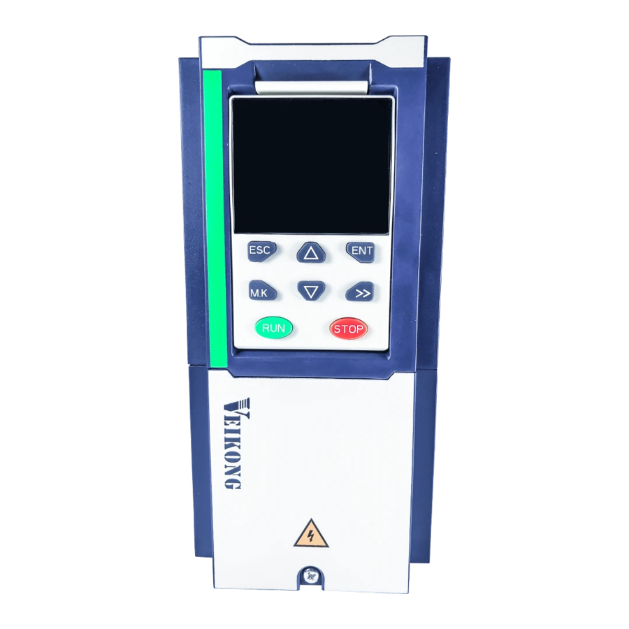
Chapter 4 Operation and display VFD500 high performance vector control frequency inverter user manual Chapter 4 Operation and display 4.1 LED Instruction of operation and display LED keyboard consists of 5 digital tubes, 7 lights, 8 keys and a potentiometer; can be used to set the parameters, status monitoring and operation control, LED keyboard shape as shown in Figure 4-1:... -
Page 37: Display Hierarchy And Menu Mode
Chapter 4 Operation and display VFD500 high performance vector control frequency inverter user manual Indicator light:Hz ·Indicate the digital display unit, all three lights off means other Indicator light:A units Indicator light:V Indicator When Hz" and "A" are lit at the same time, the unit of the currently light:HZ+A(rpm/min displayed parameter is "RPM PER MINUTE ute) -
Page 38: Digital Tube Display
Chapter 4 Operation and display VFD500 high performance vector control frequency inverter user manual If visiting access (r00.01) is the end user (in the state of user password lock), then only some function code can be accessed. User-defined mode(-USr-) In this menu mode, only 20 user-defined parameters defined are displayed. -
Page 40: Chapter 5 Function Code Table
Chapter 5 Function code table VFD500 high performance vector control frequency inverter user manual Chapter 5 Function Code Table The following is the VFD500 parameter distribution list: Classification Parameter group Page 00: Basic function Page 39 01: Frequency source selection Page 41 02: Start and stop Page 48... - Page 41 Chapter 5 Function code VFD500 high performance vector control frequency inverter user manual 00 Group Basic Function Function Parameter name Description Default Property code 0 ~ 65535 No user password status after power-on (P00.01=1): The way to set a user password to lock is that Entering the same non-zero value two times in succession P00.00...
- Page 42 Chapter 5 Function code VFD500 high performance vector control frequency inverter user manual Function Parameter name Description Default Property code 0:Speed mode 1:Torque mode If use with DI function,19:Switch between P00.05 Running mode ★ torque and speed Control and 20: torque control disabled.
- Page 43 Chapter 5 Function code VFD500 high performance vector control frequency inverter user manual 01Group frequency source selection Function Parameter name Description Default Property code 0:Digital setting 1:AI1 2:AI2 3:AI3(IO extension card) 4:AI4(IO extension card) Main frequency 5:HDI P01.00 ★ source selection (A) 6:multi-step speed 7:communication 8:PID...
- Page 44 Chapter 5 Function code VFD500 high performance vector control frequency inverter user manual Function Parameter name Description Default Property code 3:Reserved 4:Reserved 5:Pulse setting HDI 6:Reserved 7:Communication setting Lower limit frequency(P01.09)~maximum P01.08 Upper limit frequency 50.00Hz ☆ frequency (P01.06) P01.09 Lower limit frequency 0.00Hz~upper limit frequency 0.00Hz...
- Page 45 Chapter 5 Function code VFD500 high performance vector control frequency inverter user manual Function Parameter name Description Default Property code Jump frequency 2 P01.16 P01.15~maximum frequency(P01.06) 0.00Hz ☆ upper limit Jump frequency 3 P01.17 0.00Hz~(P01.18) 0.00Hz ☆ lower limit Jump frequency 3 P01.18 P01.17~maximum frequency(P01.06) 0.00Hz...
- Page 46 Chapter 5 Function code VFD500 high performance vector control frequency inverter user manual Combination method Description: Multispeed Multispeed Multispeed Multispeed Combination method terminal 4 terminal 3 terminal 2 terminal 1 Speed reference Ineffective Ineffective Ineffective Ineffective Multispeed 0 Ineffective Ineffective Ineffective effective Multispeed 1...
- Page 47 Chapter 5 Function code VFD500 high performance vector control frequency inverter user manual Function Parameter name Description Default Property code Multiple-step speed Lower limit frequency(P01.09) ~ maximum P01.26 0.00Hz ☆ 5/in-built plc 6 frequency(P01.06) Multiple step speed Lower limit frequency(P01.09) ~ maximum P01.27 0.00Hz ☆...
- Page 48 Chapter 5 Function code VFD500 high performance vector control frequency inverter user manual Function Parameter name Description Default Property code Frequency drop volume: Max frequency*P01.41*Current load/rated load Droop control filtering P01.42 0.000s~10.000s 0.050s ☆ time When several motors drive the same load, each motor's load is different because of the difference of motor's rated speed.
- Page 49 Chapter 5 Function code VFD500 high performance vector control frequency inverter user manual Function Parameter name Description Default Property code Auxiliary frequency When the main frequency ≥ this setting, the P01.48 0.00Hz ☆ effective threshold auxiliary frequency will be effective - 47-...
- Page 50 Chapter 5 Function code VFD500 high performance vector control frequency inverter user manual 02 Group Start and stop Control Function Parameter name Description Default Property code 0:Direct start Inverter will start from P02.01,After P02.02,It will go to setting frequency as per S curve 1:Speed tracking/Searching Inverter will do search for motor speed and recognize and accelerate and decelerate to...
- Page 51 Chapter 5 Function code VFD500 high performance vector control frequency inverter user manual DC braking is used to make the running motor stop & restart. Pre-excitation is used to establish asynchronous motor magnetic field, then start, improve the response speed. DC braking is only valid when start directly, the inverter performs DC braking according to P02- 06 firstly, and runs after P02-07.
- Page 52 Chapter 5 Function code VFD500 high performance vector control frequency inverter user manual Function Parameter name Description Default Property code 1.00~1.50 Over excitation braking convert some kinetic energy to motor heating by increasing motor excitation. value 1 means ineffective: value higher better performance but output current bigger This inverter can slow down the motor...
- Page 53 Chapter 5 Function code VFD500 high performance vector control frequency inverter user manual Function Parameter name Description Default Property code 1:search on the other direction when failed for given frequency tracking Deceleration time for P02.17 0.1s~20.0s 2.0s ★ speed search Current for speed 10%~150% motor rated current P02.18...
- Page 54 Chapter 5 Function code VFD500 high performance vector control frequency inverter user manual 03 Group Ramp and S curve Function Parameter name Description Default Property code Acceleration 0:linear P03.00 deceleration curve 1:S curve A ★ selection 2:S curve B Acceleration and deceleration curve, also known as "Ramp Frequency Generator (RFG)", is used to smooth the frequency command.
- Page 55 Chapter 5 Function code VFD500 high performance vector control frequency inverter user manual Function Parameter name Description Default Property code Depend P03.06 Deceleration time3 0.01~60000s same as P03.02 ☆ on model Depend P03.07 Acceleration time4 0.01~60000s same as P03.01 ☆ on model Depend P03.08...
- Page 56 Chapter 5 Function code VFD500 high performance vector control frequency inverter user manual Function Parameter name Description Default Property code S-curve Deceleration P03.14 SAME AS P03.11 0.50s ☆ Arrival time Accel and Decel time 0:Maximum frequency P03.15 ★ frequency benchmark 1:Motor rated frequency 0:1s Accel and Decel time...
- Page 57 Chapter 5 Function code VFD500 high performance vector control frequency inverter user manual Function Parameter name Description Default Property code 0.00V~10.00V ( it is used to view the port voltage of AI1. r04.09 AI 1 actual value When AI1 is a current type (0~20mA) input, multiplying this ●...
- Page 58 Chapter 5 Function code VFD500 high performance vector control frequency inverter user manual Function Parameter name Description Default Property code 0.00V~10.00V ( it is used to view the port voltage of AI4. AI4(option card) r04.21 When AI4 is a current type (0~20mA) input, multiplying this ●...
- Page 59 Chapter 5 Function code VFD500 high performance vector control frequency inverter user manual Function Parameter name Description Default Property code Curve C horizontal 0.00V~ P04.31 0.00V ☆ axis 1 P04.33 100.0% Curve C vertical axis P04.32 0.0% ~ ☆ 100.0% P04.31 Curve C horizontal P04.33...
- Page 60 Chapter 5 Function code VFD500 high performance vector control frequency inverter user manual Function Parameter name Description Default Property code P04.39 Curve D horizontal P04.41 3.00V ~ ☆ axis 2 P04.43 Curve D vertical axis 100.0% P04.42 30.0% ☆ ~ 100.0% P04.41 Curve D horizontal...
- Page 61 Chapter 5 Function code VFD500 high performance vector control frequency inverter user manual 05 Group Analog and Pulse output Function Parameter name Description Default Property code Actual output Pulse r05.00 0.00kHz~50.00kHz ● frequency HDO Pulse Output 0:Common numeric output (DO2 P07.02) P05.01 ☆...
- Page 62 Chapter 5 Function code VFD500 high performance vector control frequency inverter user manual Function Parameter name Description Default Property code r05.09 AO2 actual value 0.0%~100.0% ● AO2 output function Same as P05.02 function description P05.10 ☆ signal selection P05.11 AO2 output offset -100.0%~100.0% 0.0% ☆...
- Page 63 Chapter 5 Function code VFD500 high performance vector control frequency inverter user manual Function Parameter name Description Default Property code 28:Switch main frequency source to AI2 DI2 Numeric input P06.02 ★ 29:Switch main frequency source to AI3 function 30:Switch main frequency source to AI4 31 :...
- Page 64 Chapter 5 Function code VFD500 high performance vector control frequency inverter user manual Function Parameter name Description Default Property code 0~F: P06.36 specifies the bit0~bit15 of the parameter Define as per bit :Disable;1:Enable H000000 Bit0-bit11:DI1-DI12 P06.18 DI Forcing function Bit12-bit15:VDI1-VDI4 ★...
- Page 65 Chapter 5 Function code VFD500 high performance vector control frequency inverter user manual Function Parameter name Description Default Property code DI1 Forward DI1 operation Run (FWD) function DI2 Reverse DI2 operation RUN (REV) direction Two-line mode Two-line mode Figure1: Figure 2: forward forward command...
- Page 66 Chapter 5 Function code VFD500 high performance vector control frequency inverter user manual Function Parameter name Description Default Property code 0:no protection When command is terminal, power on and terminal effective, inverter will run Terminal 1:protection P06.31 protection ★ When command is terminal, power on and function terminal effective, inverter will not run ,so need terminal ineffective then effective, then inverter...
- Page 67 Chapter 5 Function code VFD500 high performance vector control frequency inverter user manual Function Parameter name Description Default Property code 15:Desired frequency attained 1 P08.05 DO2(HDO) Output 16:Desired frequency attained 2P08.07 P07.02 terminal function ☆ 17:Zero speed (stop without output) group 18: Zero speed (stop with output)...
- Page 68 Chapter 5 Function code VFD500 high performance vector control frequency inverter user manual Function Parameter name Description Default Property code DO1 ineffective P07.13 0.000s~30.000s 0.000s ☆ delay time DO2 effective delay P07.14 0.000s~30.000s 0.000s ☆ time DO2 ineffective P07.15 0.000s~30.000s 0.000s ☆...
- Page 69 Chapter 5 Function code VFD500 high performance vector control frequency inverter user manual 08 Group Digital output setting Function Parameter name Description Default Property code Frequency detection P08.00 0.00Hz~maximum frequency(P01.06) 50.00Hz ☆ value (FDT1) Frequency detection 0.0%~100.0% FDT1 5.0% P08.01 ☆...
- Page 70 2 When the output frequency reaches positive or negative detection amplitude of frequency detection value, DO outputs ON signal. VFD500 series inverter provides two parameters of any arrival frequency detection value, used to set frequency value and frequency detection range.
- Page 71 Chapter 5 Function code VFD500 high performance vector control frequency inverter user manual Function Parameter name Description Default Property code Output overcurrent 0.0%~300.0% P08.12 200.0% ☆ threshold motor rated time 0.000~30.000sNotice:When output Overcurrent detection P08.13 current≥P08.12 and endure P08.13 time, 0.100s ☆...
- Page 72 Chapter 5 Function code VFD500 high performance vector control frequency inverter user manual 10 Group encoder type Function Parameter name Description Default Property code 0: ABZ 1: ABZUVW P10.01 Encoder type 2: Rotary/resolver ★ 3: sin/cos encoder Consult factory when need PG card ...
- Page 73 Chapter 5 Function code VFD500 high performance vector control frequency inverter user manual Function Parameter name Description Default Property code 0 ~ 4*encoder pulse number-1 r10.14 Z pulse marking value (it is used to monitor encoder slipping and ● AB being disturbed ) - 71-...
- Page 74 Chapter 5 Function code VFD500 high performance vector control frequency inverter user manual 11 Group Motor 1 Parameter Function Parameter name Description Default Property code 0:AC asynchronous motor r11.00 Motor type 1:Synchronous motor(Special software) ● See appendix parameter 0.1kW~800.0kW when power is less than ...
- Page 75 Chapter 5 Function code VFD500 high performance vector control frequency inverter user manual Function Parameter name Description Default Property code 1: Stationary auto tuning of Asynchronous motor When do auto tuning ,motor stationary ,it can get parameter P11.11 ~P11.13。 Static self-learning can not learn all the motor parameters, so the control performance is difficult to achieve the best;...
- Page 76 Chapter 5 Function code VFD500 high performance vector control frequency inverter user manual 12 Group Motor 1 VF control parameter Function Parameter name Description Default Property code 0:linear VF 1:Multi-point VF 2:VF to the 1.3 P12.00 VF curve 3:1.7 power ★...
- Page 77 Chapter 5 Function code VFD500 high performance vector control frequency inverter user manual Function Parameter name Description Default Property code Multi-point VF Frequency multi-point VF curve F0(P12.01)~ P12.03 50.00Hz ☆ 1(F1) multi-point VF curve F2(P12.05) Multi-point VF Voltage 0.0%~100.0% P12.04 100.0% ☆...
- Page 78 Chapter 5 Function code VFD500 high performance vector control frequency inverter user manual Function Parameter name Description Default Property code 0~2000 In the SVPWM control mode, current fluctuation may occur to the motor on some frequency, especially the motor Oscillation suppression with P12.13 ☆...
- Page 79 Chapter 5 Function code VFD500 high performance vector control frequency inverter user manual 13 Group Motor 1 vector control Function Parameter name Description Default Property code Speed Proportional P13.00 0.1~100.0 12.0 ☆ Gain ASR_P1 Speed Integral Time 0.001s~30.000s 0.200s P13.01 ☆...
- Page 80 Chapter 5 Function code VFD500 high performance vector control frequency inverter user manual Function Parameter name Description Default Property code P13.07 Electric torque limit 0.0%~300.0% 160.0% ☆ Upper limit of brake P13.08 0.0%~300.0% 160.0% ☆ torque Torque current Unit:current loop adjust cycle ,0~100 P13.12 ☆...
- Page 81 Chapter 5 Function code VFD500 high performance vector control frequency inverter user manual 14 Group Torque control Function Parameter name Description Default Property code 0:Digital setting(P14.01) 1:AI1 2:AI2 Torque control input P14.00 3:AI3(IO expansion board) ★ source 4:AI4(IO expansion board) 5:HDI 6:Communication -200.0~200.0%...
- Page 82 Chapter 5 Function code VFD500 high performance vector control frequency inverter user manual Function Parameter name Description Default Property code 0: Symmetrical torque command After the motor speed exceeds the speed limit value, the torque input source sets the absolute value of the torque reference, and the direction of the torque is always the Torque setting over P14.08...
- Page 83 Chapter 5 Function code VFD500 high performance vector control frequency inverter user manual Notice: P16.05 is invisible (it is useful in vf control) and When energy saving enabled, the output current can be reduced and the power loss can be reduced when the load is light.
- Page 84 Chapter 5 Function code VFD500 high performance vector control frequency inverter user manual 18 group Asynchronous motor control advanced parameters Function Parameter name Description Default Property code Unit’s place: zero-speed processing mode in speed mode 0: no processing 1: Output DC (can prevent shaft shaking when running at zero speed) Ten’s place: low frequency excitation current SVC low frequency...
- Page 85 Chapter 5 Function code VFD500 high performance vector control frequency inverter user manual Function Parameter name Description Default Property code User-defined function pointed to by P20.xx are automatically P20.01 00.00 ☆ code 1 operated internally. Use method 2: Communication read and User-defined function P20.02 00.00...
- Page 86 Chapter 5 Function code VFD500 high performance vector control frequency inverter user manual Function Parameter name Description Default Property code User-defined function P20.23 00.00 ☆ code 23 User-defined function P20.24 00.00 ☆ code 24 User-defined function P20.25 00.00 ☆ code 25 User-defined function P20.26 00.00...
- Page 87 Chapter 5 Function code VFD500 high performance vector control frequency inverter user manual 21 Group Keypad and Display Group Function Parameter name Description Default Property code Units: UP/DOWN enable selection 0: Disable 1: Enable Ten’unit: clear selection 0: Cleared in non- Keyboard operational state 1: Not cleared P21.00...
- Page 88 Chapter 5 Function code VFD500 high performance vector control frequency inverter user manual 27.03), press the 【SHIFT】 key on the keyboard to switch between the two monitors, as shown below. Example of monitoring interface (stop) P21.12 = 0052 ★ skip when meet 0 To monitor Monitor display...
- Page 89 Chapter 5 Function code VFD500 high performance vector control frequency inverter user manual Function Parameter name Description Default Property code Load speed decimal P21.15 0~2 ☆ point digit Load speed =P27.00*P21.10 r21.16 Load speed display ● Decimal point digit defined by P21.11 0:0.01Hz;1: 1Rpm P21.17 Speed display unit...
- Page 90 Chapter 5 Function code VFD500 high performance vector control frequency inverter user manual 22 Group AC drive data and configuration Function Parameter name Description Default Property code Depend on drives power ≤7.5kW: 1kHz~12.0kHz 11kW~45kW: 1kHz~8kHz ≥55kw: 1kHz~4kHz The carrier frequency can be reduced when it came like following phenomenon: 1 The leakage current generated by the inverter is large...
- Page 91 Chapter 5 Function code VFD500 high performance vector control frequency inverter user manual Function Parameter name Description Default Property code 0.00Hz~600.00HzWhen the carrier Carrier frequency frequency is adjusted according to the P22.04 switching point 1 output frequency, the carrier frequency 10.00Hz ☆...
- Page 92 Chapter 5 Function code VFD500 high performance vector control frequency inverter user manual Function Parameter name Description Default Property code 0-Disabled 1-Enabled 2-only enable when ramp to stop Energy braking voltage P22.11 This parameter is only used to control the ☆...
- Page 93 Chapter 5 Function code VFD500 high performance vector control frequency inverter user manual 23 Group Drive protection function setting Function Parameter Description Default Property code name Unit’digit :Overvoltage stall control 0:overvoltage stall disabled 1:overvoltage stall enabled 2:overvoltage stall enabled self-adjustable The over-voltage stall function limits the amount of ...
- Page 94 Chapter 5 Function code VFD500 high performance vector control frequency inverter user manual Function Parameter Description Default Property code name Unit’s digit: Wave-by-wave current limit enable 0: invalid; 1: valid Hardware Ten’s digit short to ground enable bit P23.07 protection 0: invalid;...
- Page 95 Chapter 5 Function code VFD500 high performance vector control frequency inverter user manual Function Parameter Description Default Property code name Unit’s digit: PID feedback lost during running 0: Coast to stop 1: Fast stop 2: Stop as per stop mode Fault protection 3: Continue to run P23.20...
- Page 96 Chapter 5 Function code VFD500 high performance vector control frequency inverter user manual Function Parameter Description Default Property code name bit12-user’fault 1;bit13-user’fault 2 bit14-Reserved;bit15-Reserved Fault auto Reset P23.26 0~99 ☆ times Numeric output 0:Disabled P23.27 Action at fault ☆ 1:Enabled reset Interval time of P23.28...
- Page 97 Chapter 5 Function code VFD500 high performance vector control frequency inverter user manual Motor in self cooling mode, heat dissipation is poor when in low frequency but good in condition of high frequency . P24.01 adn P24.02 is used to set the starting point of zero and rated speed overload current in order to obtain a more reasonable under...
- Page 98 Chapter 5 Function code VFD500 high performance vector control frequency inverter user manual Default inverter is ―no motor temperature protection. To enable this protection, please confirm that present motor has a temperature sensor. (PTC means motor sensor,PTC1000 and PTC100 is different motor sensor type.if your motor have temperature sensor, you need to use our special card to connect PTC1000 or PTC100) and set temperature sensor type (P24.08) to start motor overheating protection.
- Page 99 Chapter 5 Function code VFD500 high performance vector control frequency inverter user manual 25 Group Fault tracking parameter Function Parameter name Description Default Property code - see detail chapter 6 fault diagnosis and ● r25.00 Current fault type solution Output frequency at ●...
- Page 100 Chapter 5 Function code VFD500 high performance vector control frequency inverter user manual Function Parameter name Description Default Property code Running mode status ● r26.04 See Parameter r27.10 1at fault Input terminal status Bit0~Bit6 corresponds to DI1~DI7 ● r26.05 at fault Bit12~Bit15 corresponds to VDI1~VDI4 ●...
- Page 101 Chapter 5 Function code VFD500 high performance vector control frequency inverter user manual Function Parameter name Description Default Property code Bit5: Direction of the encoder feedback frequency Reserved above Bit6 ● r27.03 Bus voltage Unit:1V ● r27.04 VF separation setting unit:0.1% ●...
- Page 102 Chapter 5 Function code VFD500 high performance vector control frequency inverter user manual Function Parameter name Description Default Property code Drives running mode ● r27.13 Reserved status 4 Accumulated power ● r27.14 Unit:hour on time Accumulated running ● r27.15 Unit:hour time r27.16 Power-on time...
- Page 103 Chapter 5 Function code VFD500 high performance vector control frequency inverter user manual Function Parameter name Description Default Property code 0.0s(disabled)~60.0s(works for master- slave system) When this function code P30.05 Modbus overtime effective, if slave do not receive data 0.0s ★...
- Page 104 Chapter 5 Function code VFD500 high performance vector control frequency inverter user manual Function Parameter name Description Default Property code When the format of the received frame is a write register, this parameter can be set to reply to the host. Modbus response P30.16 0: Reply to the host (standard Modbus...
- Page 105 Chapter 5 Function code VFD500 high performance vector control frequency inverter user manual Function Parameter name Description Default Property code number CANopen is not saved after power off CANopen send frame The number of frames sent by CANopen r31.14 ● number is not saved after power off 32 Group Profinet communication parameter...
- Page 106 Chapter 5 Function code VFD500 high performance vector control frequency inverter user manual Function Parameter name Description Default Property code modified in the drive, and the MAC address of all devices in network must duplicated (including port addresses). The port occupancy address is P32.07, with the lowest bit plus 1 (P1) and plus 2 (P2).
- Page 107 Chapter 5 Function code VFD500 high performance vector control frequency inverter user manual PID through the target signal (command) and the controlled amount of the difference between the feedback signal proportional (P), integral (I) and differential (D) operation, adjust the inverter output frequency, etc., to achieve closed-loop system, the controlled amount Stable at the target value.
- Page 108 Chapter 5 Function code VFD500 high performance vector control frequency inverter user manual When PID reference source is digital setting, PID digital setting 0~3 depends on DI terminal function 43 (preset PID terminal I ) and 44 ( preset PID terminal 2): preset PID terminal1 preset PID terminal 2 PID Digital setting value(0.1%)
- Page 109 Chapter 5 Function code VFD500 high performance vector control frequency inverter user manual Function Parameter name Description Default Property code 0: PID output is positive: when the feedback signal exceeds the PID reference value, the output frequency of the inverter will decrease to balance the PID.
- Page 110 Chapter 5 Function code VFD500 high performance vector control frequency inverter user manual Function Parameter name Description Default Property code 0.000s~0.100s This parameter determines the strength of the change ratio when PID adjustor carries out integral adjustment on the deviation of PID feedback and reference.
- Page 111 Chapter 5 Function code VFD500 high performance vector control frequency inverter user manual In some applications, one group PID parameter is not enough, different PID parameters would be adopted according to the situation. The function codes are used to switch two groups PID parameter. The setting mode of the regulator parameters P40.20~P40.22 is similar as P40.17~P40.19’s.
- Page 112 Chapter 5 Function code VFD500 high performance vector control frequency inverter user manual Function Parameter name Description Default Property code 0.0%~100.0% The output of PID system is relative to the maximum deviation of the close loop reference. As shown in the diagram below, PID adjustor stops to work during the deviation limit.
- Page 113 Chapter 5 Function code VFD500 high performance vector control frequency inverter user manual 41 Group Sleeping function Function Parameter name Description Default Property code Unit’s digit: sleep mode selection 0:no sleep function 1:Sleep by frequency 2:AI1 sleep (AI1 as pressure feedback) 3:AI2 sleep(AI2 as pressure feedback) 4:AI3 sleep (AI3 as pressure...
- Page 114 Chapter 5 Function code VFD500 high performance vector control frequency inverter user manual Function Parameter name Description Default Property code Sleep setting value by 0.00Hz~600HZ,It will sleep if value is less P41.01 0.00Hz ☆ frequency than this value When selecting frequency sleep and frequency wake-up, it must be set by P41.01 < P41.02. When the frequency source is PID setting, and the frequency wake-up must be set to PID shutdown operation: P40.39 = 1.
- Page 115 Chapter 5 Function code VFD500 high performance vector control frequency inverter user manual Function Parameter name Description Default Property code P42.04 PLC running times 1~60000 ☆ 0.0~6553.5 unit depend on P42.21 PLC step 1 running Notice: Running time do not conclude P42.05 ☆...
- Page 116 Chapter 5 Function code VFD500 high performance vector control frequency inverter user manual Function Parameter name Description Default Property code Unit’digit:step 1 ACCEL/DECEL time selector ten’digit: step 2 ACCEL/DECEL time selector Hundred’s: step 3 ACCEL/DECEL time PLC step 1-4 selector P42.22 ACCEL/DECEL time 0000...
- Page 117 Chapter 5 Function code VFD500 high performance vector control frequency inverter user manual 43 Group Programming delay-unit Function Parameter name Description Default Property code It is used to view the current output status of the delay unit. Delay unit output ●...
- Page 118 Chapter 5 Function code VFD500 high performance vector control frequency inverter user manual Function Parameter name Description Default Property code Delay unit 3 input P43.10 00.00-98.99(function code index) 00.00 ☆ parameter selection Delay unit 3 input bit P43.11 0-15 ☆ selection Delay unit3 rising P43.12...
- Page 119 Chapter 5 Function code VFD500 high performance vector control frequency inverter user manual P44.04 P44.05 Compare logical choices Hysteresis width > P44.02 variable < selector1 input variable ≥ selector1 output ≤ P44.03 = variable selector1 ≠ referemce ≈ Left: variable selector graph Right: hysteresis width graph Function Parameter name Description...
- Page 120 Chapter 5 Function code VFD500 high performance vector control frequency inverter user manual Function Parameter name Description Default Property code Unit’digit:parameter 1 bit selection 0-F (Represent 0-15),P44.18 corresponds Logic block 1 input to 0-15 bit P44.20 source Ten’digit: parameter 2 bit selection 0-F (Represent 0-15),P44.19 corresponds to 0-15 bit 0:no function;1:and;...
- Page 121 Chapter 5 Function code VFD500 high performance vector control frequency inverter user manual Function Parameter name Description Default Property code 0:no function; 1:and; 2:or; 3:not and; 4:not or; P44.25 Logic bock 2 function ☆ 5: exclusive OR 6:Ref=1 effective;Ref2=1 ineffective 7:Ref1 up effective,Ref2 up ineffective 8:Ref1 up and signal reverse 9:Ref1 up and output 200ms pulse width...
- Page 122 Chapter 5 Function code VFD500 high performance vector control frequency inverter user manual Function Parameter name Description Default Property code 5: exclusive OR 6:Ref=1 effective;Ref2=1 ineffective 7:Ref1 up effective,Ref2 up ineffective 8:Ref1 up and signal reverse 9:Ref1 up and output 200ms pulse width P44.34 Constant setting 1 0~65535...
- Page 123 Chapter 5 Function code VFD500 high performance vector control frequency inverter user manual VFD500 has two inbuilt counters: Counter 1 is a 32-bit multifunction counter with electronic gears; counter 2 is a 16- bit normal counter with no electronic gear function. Now take the counter 1 as an example to briefly explain its function and use, and the counter 2 will not be specified.
- Page 124 Chapter 5 Function code VFD500 high performance vector control frequency inverter user manual Function Parameter name Description Default Property code Unit’s digit: counting method 0: Stop counting after counting the maximum value 1: Reset after counting the maximum value, recount from 0 Ten’s digit: the action after the counter reaches the set value P45.14...
- Page 125 Chapter 5 Function code VFD500 high performance vector control frequency inverter user manual Function Parameter name Description Default Property code If the continuous running time in fire mode exceeds this setting, P58.02 will be set to 1, No-warranty time and the VFD is out of warranty. The P58.04 300s setting...
- Page 126 VFD500 high performance vector control frequency inverter user manual Chapter6 Fault diagnosis and solutions Chapter 6 Fault Diagnosis and Solution 6.1 Failure and diagnosis The VFD500 inverter has perfect protection. If a fault occurs, the inverter will act according to the fault attribute.
-
Page 127: Chapter 6 Fault Diagnosis And Solution
VFD500 high performance vector control frequency inverter user manual Chapter6 Fault diagnosis and solutions Fault Fault Name Possible Causes Solutions Display code 1: The output circuit is grounded or short circuited. 1:Eliminate external faults. 2: Motor auto-tuning is not 2: Perform the motor auto-tuning. Over performed. - Page 128 VFD500 high performance vector control frequency inverter user manual Chapter6 Fault diagnosis and solutions Fault Fault Name Possible Causes Solutions Display code 1:Check if the input power supply is abnormal, whether the input 1: Instantaneous power failure power terminal is loose, whether occurs the input contactor or the air on the input power supply or input...
- Page 129 VFD500 high performance vector control frequency inverter user manual Chapter6 Fault diagnosis and solutions Fault Fault Name Possible Causes Solutions Display code 1. Reduce the load and check the motor and mechanical 1:The load is too large or the motor conditions.
- Page 130 VFD500 high performance vector control frequency inverter user manual Chapter6 Fault diagnosis and solutions Fault Fault Name Possible Causes Solutions Display code 1: The ambient temperature is too 1:Lower the ambient high. temperature. 2: The air filter is blocked. 2: Clean the air filter. IGBT 3: The fan is damaged.
- Page 131 VFD500 high performance vector control frequency inverter user manual Chapter6 Fault diagnosis and solutions Fault Fault Name Possible Causes Solutions Display code 1 check motor and mechanical 1. Motor locked condition Encoder Er.PGL 2. Encoder pulse setting wrong 2 set correct parameter for offline encoder 3.
- Page 132 VFD500 high performance vector control frequency inverter user manual Chapter6 Fault diagnosis and solutions Fault Fault Name Possible Causes Solutions Display code 1、 PID feedback<P40.35 setting 1、 Check PID feedback signal feedback Er.FbL value and P40.36 not zero,PID 2、 P40.35 and P40.37 set lost during feedback>P40.37 setting correct parameter...
-
Page 133: Chapter 7 Selection Guide Of Inverter Accessory
VFD500 high performance vector control frequency inverter user manual Appendix A Modbus communication protocol Chapter 7 Selection Guide of inverter Accessory Selection Guide of braking component The braking resistor is used to consume the energy fed back by the motor to the inverter during braking or generating operation, so as to achieve quick braking or prevent the inverter from reporting the main circuit overvoltage fault. -
Page 134: Selection Guide Of Braking Component
VFD500 high performance vector control frequency inverter user manual Appendix A Modbus communication protocol VFD500-090G/110PT4~ As per actual load and braking power external VFD500-710GT4 D ---- Braking frequency (braking process accounts for the proportion of the entire process), by the load conditions to determine the characteristics of common occasions typical values are shown in the table below:... - Page 135 VFD500 high performance vector control frequency inverter user manual Appendix A Modbus communication protocol Encoder B+signal Encoder A-signal Encoder A signal Encoder W- signal Note: UVW is Encoder used to the Signal synchronous Encoder V- motor signal incremental Encoder encoder, no Signal need wiring Encoder U-...
- Page 136 VFD500 high performance vector control frequency inverter user manual Appendix A Modbus communication protocol Chart 7-7 Differential output type encoder DIP switch selection The wiring of the PG card and the encoder are connected one by one according to the silkscreen. Pin number diagram Pin number Name...
-
Page 137: Extension Card
VFD500 high performance vector control frequency inverter user manual Appendix A Modbus communication protocol Chart 7-8 Incremental encoder PG card with frequency division (MT500-PG-INC2) port definition In the schematic diagram of the crossover card in Table 7-5, the dial switch indicates bit 0~bit5 of the frequency division number from right to left, the frequency division range is 0~63, and the frequency division number is set to 0 and 1 when there is no frequency division. - Page 138 VFD500 high performance vector control frequency inverter user manual Appendix A Modbus communication protocol Terminal Terminal distribution Terminal function description name 1、10 Analog ground, internally isolated from COM Analog input 4 Input 0~10V: input impedance 22KΩ +24V, PT, PLC and digital input and 3、6、16 output public terminal Provides +24V power supply to the outside,...
- Page 139 0~30V 7.4 CANopen extension card The MT500-CAN1 communication card is a CANopen slave communication card for connecting VFD500 series inverters to the CANopen network. Please note that CANopen communication cannot be used simultaneously with Modbus communication. Product Features: Support Node Guard protocol, the master station can use this function to query device status;...
- Page 140 VFD500 high performance vector control frequency inverter user manual Appendix A Modbus communication protocol Figure 7-11 CANopen communication card and installation Diagram Table 7-12 CANopen communication card hardware description Description Graphic name Function description name CANopen bus terminal block, see description of Terminals Table 7-9 LED1...
-
Page 141: Chapter 8 Daily Maintenance Of Frequency Inverters
VFD500 high performance vector control frequency inverter user manual Appendix A Modbus communication protocol Chapter 8 Daily maintenance of frequency inverters Daily maintenance Due to the influence of temperature, humidity, dust and vibration, it will lead to poor heat dissipation and component aging of frequency inverter, and results in potential failure or reducing the service life of frequency inverter. -
Page 142: Warranty Items
VFD500 high performance vector control frequency inverter user manual Appendix A Modbus communication protocol Replacing Spared parts Damaged reasons How to check time 1, the blade has cracks 30000 ~ fans Bearing wear, blade aging 2 abnormal vibration, excessive 60000h noise 1, there is liquid leakage Poor input power quality,... -
Page 143: Appendix A Modbus Communication Protocol
9600bps. See parameter group set 30. Message format The VFD500 series inverter Modbus message includes the start sign, the RTU message, and the end sign。 The RTU message includes the address code, the PDU (Protocol Data Uint, the protocol data unit), and the CRC check. - Page 144 VFD500 high performance vector control frequency inverter user manual Appendix A Modbus communication protocol A.3.1 Command code 0x03 Read multiple registers or status words Request PDU Command code 1byte 0x03 0x0000~0xFFFF(high 8 initial address 2byte bit in front) 0x0001-0x0010 (1~ Number of registers 2byte 16,high 8 bit in front)
- Page 145 VFD500 high performance vector control frequency inverter user manual Appendix A Modbus communication protocol in front, first send initial address’ register value Respond PDU Command code 1byte 0x10 0x0000 ~ 0xFFFF( high Initial address 2byte 8 bit in front) 1~16(1~16, high 8 bit Number of register 2byte...
- Page 146 VFD500 high performance vector control frequency inverter user manual Appendix A Modbus communication protocol an abnormal response to inform the master of the actual situation. Abnormal response command code = normal response command code + 0x80, Abnormal code value and meaning as shown in the following table Error Name Description...
- Page 147 VFD500 high performance vector control frequency inverter user manual Appendix A Modbus communication protocol Decimal address: 27 × 256 + 10 = 6922. Example 2: Function code 14.01 (digital setting of torque reference), when no EEPROM is stored, its The hexadecimal address is: 0x0E01 (0x0E = 14, 0x01 = 1), The decimal address is: 14 ×...
- Page 148 VFD500 high performance vector control frequency inverter user manual Appendix A Modbus communication protocol 3)Inverter fault description: read the inverter fault see 25.00 function code (0x1900) VFD Fault VFD trip information address 0000:no fault 0015:current detection fault 0001:SC protection 0016:PG card feedback fault 0002:overcurrent during acceleration 0017:Encoder zero detection fault 0003:overcurrent during deceleration...
- Page 149 VFD500 high performance vector control frequency inverter user manual Appendix A Modbus communication protocol The contents of the two registers need to be combined into 32-bit numbers. 32-bit unsigned For example, read the meter r16.00: number Step 1: Read 2 registers from the starting address 0x1000 Step 2: Watt-hour meter reading = ((Uint32)0x1001 value<<16) + 0x1000 value Similar to 32-bit unsigned numbers.
- Page 150 VFD500 high performance vector control frequency inverter user manual Appendix B Profinet communication card usage Appendix B VFD500-Profinet Communication card usage instructions The MT500-Profinet communication card is a Profinet fieldbus adapter card for connecting MT500 series drives into the Profinet network. This communication card only supports drives with software version V2.90 and above.
-
Page 151: Appendix B Profinet Communication Card Usage Instructions
VFD500 high performance vector control frequency inverter user manual Appendix B Profinet communication card usage 2. Set instructions Recommended setup method: Install the PN card and power on the drive. P30.02=7 Modify the baud rate to 115200 (terminal RS485 fails, do not connect 485+/485- terminal). - Page 152 VFD500 high performance vector control frequency inverter user manual Appendix B Profinet communication card usage Drive configuration. Host computer configuration:Please correctly modify the MAC address of the drive (please do not modify other function codes of P 32 group), power on again and modify the network configuration through the host computer, at this time the network configuration information displayed by P 32 group is the network configuration saved in the PN card.
- Page 153 VFD500 high performance vector control frequency inverter user manual Appendix B Profinet communication card usage switch MT500PN MT500PN switch switch MT500PN MT500PN MT500PN MT500PN Tree type Note: In order to ensure stable work, it is recommended to use the minimum super five shielded twisted pair network cable.
- Page 154 VFD500 high performance vector control frequency inverter user manual Appendix B Profinet communication card usage PZD11 × × × × × Customization PZD12 × × × × × Customization (slave->master) Periodic reads Module type PZDlength PZD-2/2 PZD-4/4 PZD-6/6 PZD-8/8 PZD- PZD-12/12 10/10 PZD1...
- Page 155 VFD500 high performance vector control frequency inverter user manual Appendix B Profinet communication card usage This is the corresponding r group number Within-group numbering (r/p is a read-write attribute identifier that is negligible). Custom configuration address = group number*100 + group number*1 If the output current R27.06 corresponds to the customized configuration address: 27*100 + 06*1 = 2706 After the configuration is successfully written to the drive, it can be viewed in the P20 group...
- Page 156 VFD500 high performance vector control frequency inverter user manual Appendix B Profinet communication card usage 0x0008 Fault reset R27.10 bit 0: operating state 0 - down 1 - running, bit3: fault state 0 - no fault 1 - Faulty 5. TIA master configuration This manual briefly introduces the configuration of the S7-1500PLC master under TIA.
- Page 157 VFD500 high performance vector control frequency inverter user manual Appendix B Profinet communication card usage (4) Click "Add New Device", select the controller, select the corresponding PLC in the pop- up interface, pay attention to the order number (the order number code can be viewed on P LC) to match the actual PLC, and select the PLC version according to the firmware version of the actual PLC.
- Page 158 VFD500 high performance vector control frequency inverter user manual Appendix B Profinet communication card usage 5.2 Import the GSDML file (1) Click "Options" - > "Manage Generic Site Description Files (GSD)" (2) Click "..in the pop-up interface button, select the folder where the GSD file is stored, and check the GSD file to be installed, and click the "Install"...
- Page 159 VFD500 high performance vector control frequency inverter user manual Appendix B Profinet communication card usage (2)Set the IP address of the master (3) Set the master device name, if "Automatically generate PROFINET device name" is checked, the system will automatically generate a device name, if not checked, you can enter a device name by yourself.
- Page 160 VFD500 high performance vector control frequency inverter user manual Appendix B Profinet communication card usage - 158-...
- Page 161 VFD500 high performance vector control frequency inverter user manual Appendix B Profinet communication card usage 5.4 Slave communication configuration (1) In the hardware catalog on the right, find out the MT500PN slave in the following location and double-click, then add to Network View. You can also select the left mouse button to hold and drag to the network view (2) Click "Unassigned", select the IO controller, and connect the slave to the network - 159-...
- Page 162 VFD500 high performance vector control frequency inverter user manual Appendix B Profinet communication card usage (3) Select the network interface of the slave, right-click "Properties" > "General" - > "Ethernet Address" to set the IP address and device name of the slave (4) Set the IP address and subnet mask of the slave (ensure that it is a network segment with the master P LC) and do not check automatically generate the device name, fill in the automatically generated name in the drive, such as mtpn-1 (the name must be consistent...
- Page 163 VFD500 high performance vector control frequency inverter user manual Appendix B Profinet communication card usage - 161-...
- Page 164 VFD500 high performance vector control frequency inverter user manual Appendix B Profinet communication card usage 5.5 Configure the data characteristics of the slave (1) Select Slave to switch to the device view (2) Select the module under Modules on the right and double-click Add to Device (3) Select the module in "Device overview"...
- Page 165 VFD500 high performance vector control frequency inverter user manual Appendix B Profinet communication card usage If the master wants to write data to the communication address 0x7000, enter 2900 into the corresponding PZDx (master->slave). PZDx (master->slave) indicates the corresponding address written by the master to the slave. PZDx (slave->master) indicates that the master reads the corresponding address of the slave.
- Page 166 VFD500 high performance vector control frequency inverter user manual Appendix B Profinet communication card usage and IW4 stores the value read to the address mapped to PZD3 (slave->master). For example, if the previous PZD3 (master->slave) is set to 301, the value stored in QW4 will be written to function code P03.01.
- Page 167 VFD500 high performance vector control frequency inverter user manual Appendix B Profinet communication card usage 5.7 Compile and download Connect the PLC and profinet slave station, and connect the PLC programming line to the computer, set the IP address of the computer, and make it in the same network segment as the PLC.
- Page 168 VFD500 high performance vector control frequency inverter user manual Appendix B Profinet communication card usage 5.8 Profinet communication card directly replace the settings When the inverter fails to replace, the inverter can be replaced directly, and the communication card can be reinstalled and the parameters can be set. However, if the Profinet communication card is replaced, it needs to be reconfigured, and if you want to configure direct replacement, you need to set it accordingly.
- Page 169 VFD500 high performance vector control frequency inverter user manual Appendix B Profinet communication card usage the port of another device directly connected to the port, and release the mouse. Note that it must be consistent with the network connection of the actual device, if the actual PLC is connected from P1 to P1 of slave 1, and then from P2 of slave 1 to the next slave, then the same should be true in the topology.
- Page 170 VFD500 high performance vector control frequency inverter user manual Appendix B Profinet communication card usage (2) In the Edit button next to the network segment information, click with the mouse to edit the IP address and device name of the PLC, and click Settings and OK after modification. 6.2 Import the GSDML file (1) Under the File Options page, click the GSDML management icon, find the corresponding GSDML file, check the file box, and click OK to import it into the project.
- Page 171 VFD500 high performance vector control frequency inverter user manual Appendix B Profinet communication card usage 6.3 slave configuration (1) Select the PROFINET button to open the configuration setup interface. (2)First, click the controller, then set the IP address of the host PLC, the corresponding station name, and select Next after completion.
- Page 172 VFD500 high performance vector control frequency inverter user manual Appendix B Profinet communication card usage 2.Click the Add button to add the device to the configuration; 3.Assign an IP address to the configuration device, if the I P address has been set in the drive, please use the fixed IP (refer to the figure below), if not used, double-click in the blank space of the interface I P address to fill in the corresponding P address.
- Page 173 VFD500 high performance vector control frequency inverter user manual Appendix B Profinet communication card usage (6)Select the appropriate IO module, take this time as an example, choose the Standard telegram 3 module. To facilitate setting the start address of PNI and PNQ to 200. The following instructions are based on 200.
- Page 174 VFD500 high performance vector control frequency inverter user manual Appendix B Profinet communication card usage modified. Based on the pic above If the master wants to modify function code P03.01, enter 301 in PZD3 (master->slave). If the master wants to change function code P11.02, enter 1102 in PZD4 (master->slave). If the master wants to read the value of function code P27.02, enter 2702 in PZD3 (salve->master).
- Page 175 VFD500 high performance vector control frequency inverter user manual Appendix B Profinet communication card usage by PZD1 (master->slave) will be written When writing to QW202, the corresponding value of the drive communication address mapped by PZD2 (master->slave) will be written When QW204 is written, the corresponding value of the drive communication address mapped by PZD3 (master->slave) will be written.
- Page 176 VFD500 high performance vector control frequency inverter user manual Appendix B Profinet communication card usage (2) Check that the word "Connected" appears below to prove that the PLC is successfully connected, and then click Download. (3)After the download is successful, click Find Device and find that the device name and IP address are inconsistent with the configuration.
- Page 177 VFD500 high performance vector control frequency inverter user manual Appendix B Profinet communication card usage (4)Click Edit to change the device name to match the configured device name, and then click Find Device. (5)The search is complete and the IP address is consistent with the configuration. - 175-...
- Page 178 VFD500 high performance vector control frequency inverter user manual Appendix B Profinet communication card usage (6)Operate the PZD data to start the first PN device, add Mov_W instructions (PZD mapping data is 16 bits of data, word type). 7. Problems and Handling The status and description of the indicator are as follows:...
- Page 179 VFD500 high performance vector control frequency inverter user manual Appendix B Profinet communication card usage Check and eliminate the source of the fault, and the fault When the frequency reset is sufficient. For inverter fault handling, see "Fault converter fails diagnosis and countermeasures"...
Need help?
Do you have a question about the VFD500 Series and is the answer not in the manual?
Questions and answers