Veikong VFD500 User Manual
Double screen display led keyboard
Hide thumbs
Also See for VFD500:
- Operation manual (111 pages) ,
- User manual (179 pages) ,
- Operation manual (133 pages)
Advertisement
Quick Links
Advertisement

Related Manuals for Veikong VFD500


Summary of Contents for Veikong VFD500
- Page 1 VFD500 Double screen Display LED Keyboard User Manual...
-
Page 2: Product Introduction
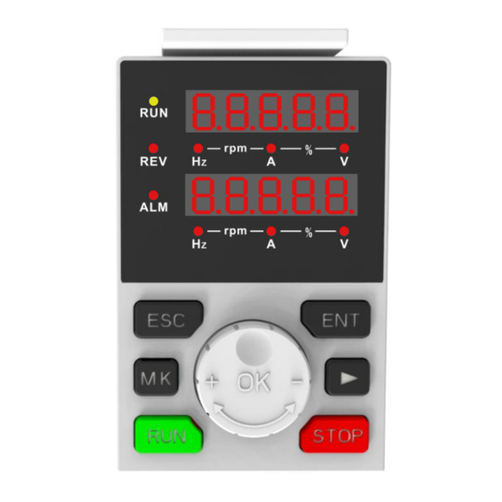
1. Product Introduction The LED keyboard consists of two rows of digital tubes, nine indicator lights, six button and one number knob; the first row is used for monitoring parameters and auxiliary display, and the second row is used for parameter setting, operatiol control and monitoring. -
Page 3: Shift:right
The specific buttons and indicator functions are shown in Table 1-1: Table 1-1 buttons and indicator functions description Number Picture Name Function previous -Return ESC: Exit Button menu. -Select list. -Enter the next menu. ENTER: -The parameters take effect Confirmation and are stored in EEPROM. - Page 4 -When the command source RUN: Run Button is the keyboard, it is used to run the inverter. -In the running state, press this button to stop running STOP:Stop (restricted parameter Button or Reset 21.03). -When a fault occurs, press this button to reset. clockwise -Rotate counterclockwise,...
- Page 5 Note: Communication distance <30m 2. Hierarchical display and menu mode The display of the VFD500 dual-line display LED keyboard is divided into two lines, the first line is used for monitoring and auxiliary display, and the second line is used for switching monitoring, menu mode, function code selection, parameter editing and viewing.
- Page 6 locked), Then only individual function codes can be accessed. User-defined mode(-USr-) ◆ In this menu mode, only 20 groups of user-defined parameters are displayed. ◆ calibration mode(-vrF-) In this menu mode, only the parameters that differ from the factory values are displayed.
-
Page 7: Operation Example
-Count the number of Communication error PAr.03 communication errors since the statistics keyboard was powered on Table 1-2 PAr.xx function code details in LED setting mode 3. Operation example The three switchable interfaces after power-on, the respective operations are as follows: The interface can be switched by the [ESC] button. - Page 8 Monitoring status SHIFT SHIFT SHIFT (Monitoring (Monitoring (Monitoring (Monitoring quantity 1) quantity 2) quantity 3) quantity 4) (2) Menu list interface Menu list (Standard (User-defined (LED setting (Checkout mode) DOWN DOWN DOWN mode) mode) mode) ENTER ENTER ENTER ENTER 【UP、DOWN、SHIFT】 【UP、DOWN、SHIFT】...
- Page 9 Function code selection status 【UP/DOWN/SHIFT】 【UP/DOWN/SHIFT】 【UP/DOWN/SHIFT】 【UP/DOWN/SHIFT】 parameter Edit/View status ENTER ENTER ENTER ENTER 【UP/DOWN/SHIFT】 【UP/DOWN/SHIFT】 【UP/DOWN/SHIFT】 【UP/DOWN】 Note: 1)Dual-line monitoring cannot monitor "32-bit data" and "binary data". 2)In the monitoring state of the second line, rotate “UP and DOWN” to set the frequency or torque in real time.
- Page 10 32 digits: Dot1 is used to distinguish between the upper and below screens, Light up means the up screen displayed (high 5 digits),Off means down screen displayed (lower 5 digits). The display range of 32-bit unsigned numbers is 0 ~ 4294967295. As shown 4294967295: Binary data display ◆...
- Page 11 Lower screen, lower 8 digits ◆ Parameter attribute identification The leftmost digital tube of the editable parameter displays "P"; The leftmost digital tube of the read-only parameter displays "r", Show as the picture: “r”means read only ◆ Specific symbol In some states, the digital tube will display a specific symbol. The meaning of specific symbols is shown in the table below: Symbol Significance...
- Page 12 -Fault code, "XXX" is the fault type, For details, Er.xxx please refer "VFD500 User Manual Troubleshooting" Communication failure code, "XXX" is the failure type, Cr.001-Cr005 represents the data error, Cr.006 Cr.xxx is the communication timeout, and Cr.007 is the CRC check error.
Need help?
Do you have a question about the VFD500 and is the answer not in the manual?
Questions and answers