Table of Contents
Advertisement
VFD500M Series
High performance smart Inverter
User Manual
ShenZhen VEIKONG Electric CO., Ltd.
ShenZhen VEIKONG Electric CO., Ltd.
Factory Address:
Block E01,first industrical park lingbei 5 road ,phoenix comm
unity,fuyong street , Bao'anDistrict, Shenzhen ,China
R&D Center: Jin yu cheng building A,Bu Long Rd Bantian Town
,Longgang district Shenzhen City,China
Technical Support Hotline: +86-0755-89587650
Web Site:
www.veikong-electric.com
ShenZhen VEIKONG Electric CO., Ltd.
Whatsapp +8615989436541
Advertisement
Table of Contents

Related Manuals for Veikong VFD500M Series


Summary of Contents for Veikong VFD500M Series
- Page 1 VFD500M Series High performance smart Inverter User Manual ShenZhen VEIKONG Electric CO., Ltd. ShenZhen VEIKONG Electric CO., Ltd. Factory Address: Block E01,first industrical park lingbei 5 road ,phoenix comm unity,fuyong street , Bao'anDistrict, Shenzhen ,China R&D Center: Jin yu cheng building A,Bu Long Rd Bantian Town...
- Page 2 Preface Thank you for purchasing the VFD500M series high performance vector and torque control frequency inverter VFD500M is a economical vector control inverter for asynchronous motor control .High reliability, easy to use, compact size and rich functions; support open-loop VF control and speed sensorless vector control,...
- Page 3 Contents Chapter 1 Safety Information and Precautions ..................1 1.1 Safety Precautions ........................... 1 1.2 Precaution ............................2 Chapter 2 Product Information ........................4 2.1 Designation Rules ..........................4 2.2Product series instruction ........................ 4 2.3Technical Specifications ........................5 Chapter 3 Product appearance and Installation Dimension ............8 3.1 Product appearance and installation .....................
- Page 4 VFD500M vector control frequency inverter user manual Chapter 1 Safety information and precautions Chapter 1 Safety Information and Precautions Safety Definitions: In this manual, safety precautions are divided into the following two categories: indicates that failure to comply with the notice will result in serous injury or even death indicates that failure to comply with the notice will result in moderate or minor injury andequipment damage Read this manual carefully so that you have a thorough understanding.
- Page 5 VFD500M vector control frequency inverter user manual Chapter 1 Safety information and precautions Use stage Security Level Precautions the external circuit is short-circuited, the connection is tightened, or cause damage to the drive! ➢ No part of the drive need to withstand voltage test, the product has been made before the test.
- Page 6 VFD500M vector control frequency inverter user manual Chapter 1 Safety information and precautions ⚫ Altitude and derating use In areas above 1000m above sea level, it is necessary to derate the inverter due to poor air quality due to poor air quality.
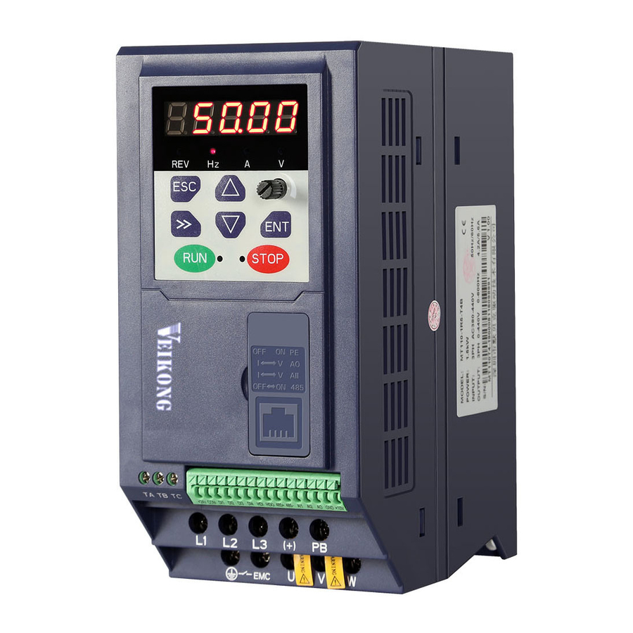
- Page 7 VFD500M vector control frequency inverter user manual Chapter 2 Product information Chapter 2 Product Information 2.1 Designation Rules Name plate: 2-1 name plate Model instruction: 2-2model instruction 2.2Product series instruction Table 2-1VFD500M inverter models and technical data...
- Page 8 VFD500M vector control frequency inverter user manual Chapter 2 Product information Output Adapt Power Input current(A) able Brake Model capacity current SIZE Motor Unit Heavy Light (KVA) (KW) load load 3 phase: 380V-480V,50/60Hz VFD500M-R75GT4B 0.75 VFD500M-1R5GT4B SIZE B Internal VFD500M-2R2GT4B VFD500M-4R0GT4B 11.6 10.5...
- Page 9 VFD500M vector control frequency inverter user manual Chapter 2 Product information 5Hz(V/f) Speed response 20Hz(SVC) 0.00~600.00Hz(V/f) frequency range 0.00~200.00Hz(SVC) Input frequency Digital setting: 0.01 Hz resolution Analog setting: maximum frequency x 0.1% 150%/0.5Hz(V/f) Startup torque 180%/0.25Hz(SVC) Torque control SVC:within 5Hz10%,above 5Hz5% accuracy VC:3.0% V / f curve type: straight line, multipoint, power function, V / f...
- Page 10 VFD500M vector control frequency inverter user manual Chapter 2 Product information smoke, vapor, drip or salt. 0-3000m.inverter will be derated if altitude higher than1000m and Altitude rated output current will reduce by 1% if altitude increase by 100m -10° C~ +40° C,maximum 50° C (derated if the ambient temperature is Ambient between 40°...
- Page 11 Chapter 3 Product appearance and Installation Dimension Product appearance and installation 3.1.1 Product appearance 3.1.2Appearance and Mounting Hole Dimension Φd Remark: is screw hole diameter for installing Table 3-1 VFD500M series appearance and installation dimension Appearance and installation dimension (mm) SIZE TYPE Mounting Φd screws M4×16 SIZE A ø5.0...
- Page 12 Chapter 3 Product appearance VFD500M vector control frequency inverter user manual 3.2Wiring 3.2.1 Standard wiring diagram Braking Resistor 3PH AC power input 380V~ 50/60Hz breake reactor R/L1 S/L2 T/L3 Main circuit Control circuit RS485 port Digital input1 485+ Digital input2 485- Digital input3 AO output:...
- Page 13 Chapter 3 Product appearance VFD500M vector control frequency inverter user manual 3.2.2 Main Circuit Terminals Figure 3-4 SIZE A main circuit terminal diagram Figure 3-5 SIEZ B main circuit terminal diagram Figure 3-6 SIEZ C main circuit terminal diagram Table 3-2 Function description of the main circuit terminal of the inverter Terminal Function instruction (only...
- Page 14 Chapter 3 Product appearance VFD500M vector control frequency inverter user manual 3.2.3 Terminal screws and wiring specifications Table 3-3 Main circuit cable and screw specifications Power terminal Ground terminal Tightening Cable Cable Tightening Model number Scre scre torque diameter diameter torque (Nm)...
- Page 15 Chapter 3 Product appearance VFD500M vector control frequency inverter user manual ◆It is forbidden to connect the output terminal of the inverter to the capacitor or LC/RC noise filter with phase lead, otherwise, the internal components of the inverter may be damaged. ◆When contactor is installed between the inverter and the motor, it is forbidden to switch on/off the contactor during the running of the inverter, otherwise, there will be large current flowing into the inverter, triggering the inverter protection action.
- Page 16 Chapter 3 Product appearance VFD500M vector control frequency inverter user manual Table 3-3 VFD500M control circuit terminal instruction Type Terminal Terminal Terminal function description Symbol Name 10.10V±1% Maximum output current:10mA,it provides power +10V Input voltage supply to external potentiometer with resistance range of:1KΩ~51KΩ...
- Page 17 Chapter 3 Product appearance VFD500M vector control frequency inverter user manual Type Terminal Terminal Terminal function description Symbol Name Open Open collector output:same as DO1 collector output(size A) High-speed pulse output:0~50KHz /High-speed pulse output TA-TB:nomal close (Size A support NC only) Relay output TA/TB/TC Relay output...
- Page 18 Chapter 3 Product appearance VFD500M vector control frequency inverter user manual A、Use internal power B、Use external power Figure 3-9 Wiring diagram of the switch output terminal Note: The multi-function terminal output is open collector output, and the maximum allowable current is 50mA. When using the internal power supply, if driving an inductive load, add an absorption circuit, such as an RC snubber circuit or a freewheeling diode.
- Page 19 Chapter 4 Operation and display VFD500M vector control frequency inverter user manual Chapter 4 Operation and display 4.1 LED Instruction of operation and display LED keyboard consists of 5 digital tubes, 7 lights, 8 keys and a potentiometer; can be used to set the parameters, status monitoring and operation control, LED keyboard shape as shown in Figure 4-1:...
- Page 20 Chapter 4 Operation and display VFD500M vector control frequency inverter user manual ·Always light:Hz Indicator light:Hz ·flicker:Rpm Indicator light:A ·Indicate the digital display unit, all three lights off menas other units Indicator light:V • Off: indicates a stop condition. Running lights •...
- Page 21 Chapter 4 Operation and display VFD500M vector control frequency inverter user manual ◆ Binary data display Binary number currently only supports 16 digits, points left and right screen display. The leftmost digital tube is used to distinguish the left and right screens: the top digit segment lights up for the left panel and the bottom segment segment lights for the right panel.
- Page 22 Chapter 5 Function code table VFD500M vector control frequency inverter user manual Chapter 5 Function Code Table The following is the VFD500M parameter distribution list: Classification Parameter group Page 00:Basic function Page 22 01:Frequency source selection Page24 02:Start and stop Page 29 03:Ramp and S curve Page 31...
- Page 23 Chapter 5 Function code table VFD500M vector control frequency inverter user manual Function Parameter name Description Default Property code 00Group Basic Function 0 ~ 65535 ➢ No user password status (P00.01 = 1 after power-on): Entering the same non-zero value twice in succession sets a user password and enters lockout.
- Page 24 Chapter 5 Function code table VFD500M vector control frequency inverter user manual Function Parameter name Description Default Property code DI status Numeric frequency 00.00Hz~maximum frequency(Set P21.17=1 P00.07 50.00Hz ☆ setting to change its unit to 1Rpm) 0:Forward 1:Reverse ➢ It is only for keypad control to change running direction by giving frequency symbol to be reverse)If command by P00.08...
- Page 25 Chapter 5 Function code table VFD500M vector control frequency inverter user manual Functio Parameter name Description Default Property n code 01Group frequency source selction 0:Digital setting 1:AI1 2:AI2 3:Reserved 4:Reserved 5:HDI Main frequency source P01.00 6:multi-step speed ★ selection (A) 7:communication 8:PID 9:Internal PLC...
- Page 26 Chapter 5 Function code table VFD500M vector control frequency inverter user manual Functio Parameter name Description Default Property n code 6:Reserved 7:Communication setting 8:Reserved 9:Reserved 10:Potentiometer Lower limit frequency(P01.09)~maximum P01.08 Upper limit frequency 50.00Hz ☆ frequency (P01.06) P01.09 Lower limit frequency 0.00Hz~upper limit frequency 0.00Hz ☆...
- Page 27 Chapter 5 Function code table VFD500M vector control frequency inverter user manual Functio Parameter name Description Default Property n code Unit’digit:0 phase reference source set by 0-multi-step speed(P01.21) 1-preset frequency (P00.07) 2:AI1 3:AI2 Multi-step speed 4:Reserved P01.19 ★ reference source 5:Reserved 6:HDI pulse 7:Communication...
- Page 28 Chapter 5 Function code table VFD500M vector control frequency inverter user manual Functio Parameter name Description Default Property n code Rotation direction direction 0:forward direction 1:reverse direction Multiple step speed 0/in- Lower limit frequency (P01.09) ~ maximum P01.21 0.00Hz ☆ built plc 1 frequency (P01.06) Multiple step speed 1/in-...
- Page 29 Chapter 5 Function code table VFD500M vector control frequency inverter user manual Functio Parameter name Description Default Property n code digit when power failure Ten’s digit: 0:Non-zero cleaning at power failure 1:Save at power failure UP/DOWN offset Hundred’s digit: UP/DOWN near to zero 0: Forbidden 1:Enable 0.00~1.00...
- Page 30 Chapter 5 Function code table VFD500M vector control frequency inverter user manual Functio Parameter name Description Default Property n code This function is mostly used in textile and chemical industry and some application such as traversing and winding so it is used for balancing the workload allocation when multiple motors are used to drive the same load. The output frequency of the frequency inverters decreases as the load increases.
- Page 31 Chapter 5 Function code table VFD500M vector control frequency inverter user manual Function Parameter name Description Default Property code 02 Group Start and stop Control 0:Direct start Inverter will start from P02.01,After P02.02,It will go to setting frequency as per S curve 1:Speed tracking/Searching P02.00 Starting mode...
- Page 32 Chapter 5 Function code table VFD500M vector control frequency inverter user manual Function Parameter name Description Default Property code decrease lower than delaying frequency at stop (P02.13),inverter will block pulse output after delaying time at stop (P02.14).if run command comes during delaying time,inverter will restart.it is useful to some application with jog function The minimum blocking...
- Page 33 Chapter 5 Function code table VFD500M vector control frequency inverter user manual Function Parameter Description Default Property code name 03 Group Ramp and S curve Acceleration and 0:linear P03.00 deceleration 1:S curve A ★ curve selection 2:S curve B Acceleration and deceleration curve, also known as "Ramp Frequency Generator (RFG)", is used to smooth the frequency command.
- Page 34 Chapter 5 Function code table VFD500M vector control frequency inverter user manual Function Parameter Description Default Property code name Depend P03.06 Deceleration time3 0.01~60000s same as P03.02 ☆ on model Depend P03.07 Acceleration time4 0.01~60000s same as P03.01 ☆ on model Depend P03.08 Deceleration time4...
- Page 35 Chapter 5 Function code table VFD500M vector control frequency inverter user manual Function Parameter Description Default Property code name begin time S-curve P03.14 Deceleration SAME AS P03.11 0.50s ☆ Arrival time Accel and Deceltime 0:maximum frequency P03.15 ★ frequency 1:Motor rated frequency benchmark 0:1s Accel and Decel...
- Page 36 Chapter 5 Function code table VFD500M vector control frequency inverter user manual Function Parameter Description Default Property code name 3:Curve D Ten’unit:when input signal lower than minimum input 0:equal to minimum input 1:equal to 0.0% P04.08 AI1 filter time 0.000s~10.000s 0.100s ☆...
- Page 37 Chapter 5 Function code table VFD500M vector control frequency inverter user manual Function Parameter Description Default Property code name Curve B vertical -100.0%~ P04.28 0.0% ☆ axis 1 100.0% Curve B horizontal P04.27~ P04.29 10.00V ☆ axis 2 10.00V Curve B vertical -100.0%~...
- Page 38 Chapter 5 Function code table VFD500M vector control frequency inverter user manual Function Parameter Description Default Property code name Curve D vertical -100.0%~ P04.46 100.0% ☆ axis 4 100.0% Description: The range of HDI, AI1 ~ AI4 mapping curve: ➢ For frequency setting, 100% corresponds to the maximum frequency P01.06. ➢...
- Page 39 Chapter 5 Function code table VFD500M vector control frequency inverter user manual 05 Group Analog and Pulse output Actual output Pulse r05.00 0.00kHz~50.00kHz ● frequency 0:Common numeric output (DO2 P07.02) P05.01 HDO Pulse Output type ☆ 1:high frequency pulse output (Hdo) 0:Running frequency(0~max frequency)...
- Page 40 Chapter 5 Function code table VFD500M vector control frequency inverter user manual 06 Group Multi-function Digital input Bit0~Bit6 Correspond to DI1~DI7 r06.00 DI port status ● Bit12~Bit15 Correspond to VDI1~VDI4 0:No function 1:Run terminal 2:Reverse/Forward and reverse switchover P06.01 DI1 Numeric input function ★...
- Page 41 Chapter 5 Function code table VFD500M vector control frequency inverter user manual 38:User-defined fault 2 39:PID pause 40:PID integral pause 41:PID parameter Switchover 42:PID Positive/negative reaction switch 43:Preset PID terminal 1 44:Preset PID terminal 2 45:PID Main and Auxaliary command switch 46:PID Main and Auxaliary feedback switch 47:Simple PLC status reset 48:Simple PLC time stop...
- Page 42 Chapter 5 Function code table VFD500M vector control frequency inverter user manual P06.26 DI3 ineffective delay time 0.000s~30.000s 0.000s ☆ 0.000s~30.000s P06.27 DI4 Effective delay time 0.000s ☆ 0.000s~30.000s P06.28 DI4 ineffective delay time 0.000s ☆ 0:2-wire mode (FWD+REV)1 Two wire/3wire operation 1:2-wire mode RUN+DIRECTION)2 P06.29 ★...
- Page 43 Chapter 5 Function code table VFD500M vector control frequency inverter user manual When command is terminal ,power on and terminal effective,inverter will run 1:protection When command is terminal ,power on and terminal effective, inverter will not run ,so need terminal ineffective then effective,then inverter will run P06.32 DI terminal on/ready time...
- Page 44 Chapter 5 Function code table VFD500M vector control frequency inverter user manual 20:Output current exceed limit 21:Counter 1 setting value arrival VDO1(virtual DO1) output P07.09 ☆ 22:Counter 1 setting value arrival Terminal function 23:Simple PLC cycle finish 24:IGBT temperature arrival 25:Drive overload pre-warning 26: Motor overload pre-warning 27: Motor overheat pre-warning...
- Page 45 Chapter 5 Function code table VFD500M vector control frequency inverter user manual 08Group Digital output setting Frequency detection value P08.00 0.00Hz~maximum frequency(P01.06) 50.00Hz ☆ (FDT1) Frequency detection P08.01 0.0%~100.0% FDT1 5.0% ☆ hysteresis 1 Frequency detection value P08.02 0.00Hz~maximum frequency(P01.06) 50.00Hz ☆...
- Page 46 Chapter 5 Function code table VFD500M vector control frequency inverter user manual Output overcurrent 0.0%~300.0% P08.12 200.0% ☆ threshold motor rated time 0.000~30.000sNotice:When output Overcurrent detection P08.13 current≥P08.12 and endure P08.13 0.100s ☆ delay time time,corresponding DOoutput effective signal Setting Running arrival P08.16 0~65530h ☆...
- Page 47 Chapter 5 Function code table VFD500M vector control frequency inverter user manual 11 Group Motor 1 Parameter r11.00 Motor type 0:AC asynchronous motor ● 0.1kW~800.0kW ➢ when power is less than 1kw ,0.75kw set to 0.8 as per round up principle ,0.55kw motor set 0.6 P11.02 Motor rated power...
- Page 48 Chapter 5 Function code table VFD500M vector control frequency inverter user manual Asynchronous motor Unit:0.01mΩ(P11.02>=30kW) Rotor resistor of Unit:0.001Ω(P11.02<30kW) P11.12 Depend ★ Asychronous motor Unit:0.01mΩ(P11.02>=30kW) Leakage inductance of Unit:0.01mH(P11.02<30kW) P11.13 Depend ★ Asychronous motor Unit:0.001mH(P11.02>=30kW) Mutual inductance of Unit:0.1mH(P11.02<30kW) P11.14 Depend ★...
- Page 49 Chapter 5 Function code table VFD500M vector control frequency inverter user manual 12 Group Motor 1 VF control parameter 0:linear VF 1:Multi-point VF 2:VF to the 1.3 P12.00 VF curve 3:1.7 power ★ 4:2.0 power 5:VFcomplete separation 6:VF Half separation ➢...
- Page 50 Chapter 5 Function code table VFD500M vector control frequency inverter user manual 1(F2) VF curve F3(P12.08) P12.06 Multi-point VF Voltage 2(V2) 0.0%~100.0% 100.0% ☆ Multi-point VF Frequency P12.07 multi-point VF curveF2(P12.05)~600.00Hz 50.00Hz ☆ 3(F3) P12.08 Multi-point VFVoltage 3(V3) 0.0%~100.0% 100.0% ☆...
- Page 51 Chapter 5 Function code table VFD500M vector control frequency inverter user manual 0:digital setting 1:AI1 2:AI2 3:Reserved Voltage source for VF 4:Reserved P12.20 ★ separation 5:pulse setting HDI 6:Reserved 7:communication 8:PID 9: Potentiometer Digital setting for VF P12.21 0.0%~100.0% 0.0% ☆...
- Page 52 Chapter 5 Function code table VFD500M vector control frequency inverter user manual 13 Group Motor 1 vector control Speed Proportional Gain P13.00 0.1~100.0 12.0 ☆ ASR_P1 Speed Integral Time P13.01 0.001s~30.000s 0.100s ☆ constant ASR_T1 Speed Proportional Gain P13.02 0.1~100.0 ☆...
- Page 53 Chapter 5 Function code table VFD500M vector control frequency inverter user manual 14 Group Torque control 0:digital setting 1:AI1 2:AI2 3:AI3(reserved) P14.00 Torque setting ★ 4:AI4(reserved) 5:HDI 6: Communication 7: Potentiometer P14.01 Torque digital setting -200.0~200.0% ☆ Benchmark 10.0%~300.0% Notice:torque benchmarks for analog inputs and P14.02 Maximum torque 200.0%...
- Page 54 Chapter 5 Function code table VFD500M vector control frequency inverter user manual 16 Group Energy saving control parameter Electricity meter count r16.00 Unit:KW/H ● (32BIT) Unit:0.1kw,output power will be negative in r16.02 Output power ● regen state r16.03 Power factor -1.000~1.000 ●...
- Page 55 Chapter 5 Function code table VFD500M vector control frequency inverter user manual 20 Group User-defined function code menu User-defined function P20.00 00.00 ☆ code 1 User-defined function code P20.01 00.00 ☆ User-defined function code P20.02 00.00 ☆ User-defined function code P20.03 00.00 ☆...
- Page 56 Chapter 5 Function code table VFD500M vector control frequency inverter user manual 21 Group Keypad and Display Group Units: UP/DOWN enable selection 0: Disable 1: Enable Ten’unit: clear selection 0: Cleared in non- Keyboard UP/DOWN operational state 1: Not cleared P21.00 0110 ★...
- Page 57 Chapter 5 Function code table VFD500M vector control frequency inverter user manual 27.03), press the 【SHIFT】 key on the keyboard to switch between the two monitors, as shown below. The rules for running the monitoring interface are the same as the shutdown monitoring interface, and will not be repeated Unit’s digit: quick editing function selection 0: invalid...
- Page 58 Chapter 5 Function code table VFD500M vector control frequency inverter user manual Keyboard potentiometer P21.19 0.000s~10.000s 0.100s ☆ filter time 0.00V~10.00V Keyboard potentiometer Used to view the port voltage of AI2. When AI2 is r21.20 ● actual value a current type (0~20mA) input, multiplying this value by 2 is the input current (mA) of the AI2 port.
- Page 59 Chapter 5 Function code table VFD500M vector control frequency inverter user manual 22 Group AC drive data and configuration Depend on drives power ≤7.5kW: 1kHz~12.0kHz 11kW~45kW: 1kHz~8kHz ≥55kw: 1kHz~4kHz The carrier frequency can be reduced when it came like following phenomenon: 1 The leakage current generated by the inverter is large P22.00...
- Page 60 Chapter 5 Function code table VFD500M vector control frequency inverter user manual It is only used in special situation 10%~100%(modulation percentage) When P22.06 is set to 1, increasing this P22.07 DPWM switching point ★ setting vaule can reduce the electromagnetic noise in the middle speed section.
- Page 61 Chapter 5 Function code table VFD500M vector control frequency inverter user manual 23 Group Drive protection function setting ➢ Unit’digit :Overvoltage stall control 0:overvoltage stall disabled 1:overvoltage stall enabled 2:overvoltage stall enabled self-adjustable ➢ The over-voltage stall function limits the amount of power generated by the motor by extending the deceleration time or even increasing the speed, avoiding over-voltage on the DC side and reporting...
- Page 62 Chapter 5 Function code table VFD500M vector control frequency inverter user manual Detection value of too P23.12 0.0%~100.0%(motor rated frequency) 20.0% ☆ large speed deviation Detection value of too 0.0s~30.0s P23.13 0.0s ☆ large speed deviation 0.0:shielding Input phase loss 0.0s~30.0s P23.14 8.0s...
- Page 63 Chapter 5 Function code table VFD500M vector control frequency inverter user manual 1: fast stop 2: stop as per stop mode 3: continue to run Hundred’s unit: PG card fault(reserved) 0: coast to stop 1: fast stop 2: stop as per stop mode 3: continue to run Thousand’s unit: off load fault 0: coast to stop...
- Page 64 Chapter 5 Function code table VFD500M vector control frequency inverter user manual 24 Group motor Protection parameter Motor overload protection P24.00 0.20~10.00 1.00 ☆ gain Motor overload starting P24.01 50.0%~150.0% 100.0% ☆ current at zero speed Motor overload starting P24.02 50.0%~150.0% 115.0% ☆...
- Page 65 Chapter 5 Function code table VFD500M vector control frequency inverter user manual 1: Enable software overload protection P24.12 Off load protection 0:effective 1:ineffective ☆ P24.13 Off load detection level 0.0%-100% 10.0% ☆ P24.14 Off load detection time 0.000s-60.000s 1.000s ☆ Off load=unload If output current is lower than offload detection level (P24.13) and this status continues for offload detection time (P24.14) when offload detection protection is enabled...
- Page 66 Chapter 5 Function code table VFD500M vector control frequency inverter user manual 25 Group Fault tracking parameter Current fault - see detail chapter 6 fault diagnosis and ● r25.00 type solution Output ● r25.01 frequency at Unit:0.01Hz fault Output current r25.02 Unit:0.1A ●...
- Page 67 Chapter 5 Function code table VFD500M vector control frequency inverter user manual fault Running mode ● r26.04 See Parameter r27.10 status 1at fault Input terminal Bit0~Bit6 corresponds to DI1~DI7 ● r26.05 status at fault Bit12~Bit15 corresponds to VDI1~VDI4 working time at ●...
- Page 68 Chapter 5 Function code table VFD500M vector control frequency inverter user manual 27 Group Monitoring parameter Running ● r27.00 It can set unit as per Parameter P21.07 frequency ● r27.01 Set frequency It can set unit as per Parameter P21.07 bit0:direction of running frequency bit1:direction of setting frequencybit2:...
- Page 69 Chapter 5 Function code table VFD500M vector control frequency inverter user manual Accumulated ● r27.14 Unit:hour power on time Accumulated ● r27.15 Unit:hour running time Heat sink ● r27.18 Unit:0.1 ℃ temperature ● r27.19 Main frequency Unit:0.01Hz Auxiliary ● r27.20 unit:0.01Hz frequency UpDown offset...
- Page 70 Chapter 5 Function code table VFD500M vector control frequency inverter user manual data received count in cycle Number of process Add 1 after transmiss one data,0~ ● r30.07 data transmission 65536 count in cycle Each time an CRC error frame is Number of error received, this value is incremented by 1,0 ●...
- Page 71 Chapter 5 Function code table VFD500M vector control frequency inverter user manual 40 Group PID function PID final output ● r40.00 Read only unit:0.1% value PID final set ● r40.01 Read only unit:0.1% value final ● r40.02 Read only unit:0.1% feedback value PID deviation ●...
- Page 72 Chapter 5 Function code table VFD500M vector control frequency inverter user manual PID preset P40.09 0.0~P40.05 0.0% ☆ setting 3 When PID reference source is digital setting, PID digital setting 0~3 depends on DI terminal function 43 (preset PID terminal I ) and 44 ( preset PID terminal 2): preset PID terminal1 preset PID terminal 2 PID Digital setting value(0.1%)
- Page 73 Chapter 5 Function code table VFD500M vector control frequency inverter user manual value 6:Max(fdb1,fdb2) Take fdb1.fdb2 bigger value 7: (ref1+ref2)/2 8: ref1 and ref2 conversion 9: Reserved 10:Reserved 11:Reserved 12: Reserved Sqrt means square root calculation,eg:sqrt(50.0%)=70.7% 0-positive P40.14 PID output feature ☆...
- Page 74 Chapter 5 Function code table VFD500M vector control frequency inverter user manual KP1, TI1, TD1 are used when DI terminal No. 41 function is invalid; KP2, TI2, TD2 are used when valid 2:automatic switchover based on deviation The absolute value of PID command and feedback deviation is less than P40.24, using KP1, TI1, TD1;...
- Page 75 Chapter 5 Function code table VFD500M vector control frequency inverter user manual time of PID feedback loss PID operation at 0-No PID operation at stop P40.39 ☆ stop 1-PID operation at stop PID command P40.40 for accel and 0.0s~6000.0s 0.0s ☆...
- Page 76 Chapter 5 Function code table VFD500M vector control frequency inverter user manual cannot be activated, and Pay special attention to avoid accident when use Sleep setting 0.00Hz~600HZ,It will sleep if value is less P41.01 value by 0.00Hz ☆ than this value frequency Wake up 0.00hz~600.00hz, ,It will wake up if value is...
- Page 77 Chapter 5 Function code table VFD500M vector control frequency inverter user manual saving PLC running P42.04 1~60000 ☆ times 0.0~6553.5 unit depend on P42.21 PLC step 1 Notice:Running time do not conclude P42.05 ☆ running time acceleration and deceleration time,same as following PLC step 2 P42.06...
- Page 78 Chapter 5 Function code table VFD500M vector control frequency inverter user manual 1- ACCEL/DECEL time 2 2- ACCEL/DECEL time 3 3- ACCEL/DECEL time 4 Unit’digit: ACCEL/DECEL time 5 Ten’digit: ACCEL/DECEL time 6 Hundred’digit: ACCEL/DECEL time 7 PLC step 5-8 Thousand’digit: ACCEL/DECEL time 8 P42.23 ACCEL/DECEL 0000...
- Page 79 Chapter 5 Function code table VFD500M vector control frequency inverter user manual Delay control parameter Logic choice Parameter bit selection Parameter P43.04,P43.05 P43.01 P43.03=x P43.02 Delay unit 1 output Parameter input Ref 0-not (P43.02 value of function reversed P43.04 P43.05 code) 1-reverse Take ref from 0-15 value...
- Page 80 Chapter 5 Function code table VFD500M vector control frequency inverter user manual input bit selection Delay relay 4 on P43.16 0.0s~3000.0s 00.00 ☆ delay time Delay unit4 off P43.17 0.0s~3000.0s 0.0s ☆ delay time Delay unit 5 P43.18 input parameter 00.00-98.99(function code index) 00.00 ☆...
- Page 81 Chapter 5 Function code table VFD500M vector control frequency inverter user manual P44.05 Comparison Hysteresis width logic > P44.04 P44.02 < Comparator 1 input ≥ Comparator 1 output ≤ = P44.03 Comparator 1 ref ≠ ≈ Input value Hysteresis value width >...
- Page 82 Chapter 5 Function code table VFD500M vector control frequency inverter user manual Variable selector P44.13 3 hysteresis 0~65535 ☆ width Variable selector P44.14 4 input 00.00-98.99(function code index) 00.00 ☆ parameter Variable selector P44.15 00.00-98.99(function code index) 00.00 ☆ 4 threshold Variable selector 0:>;...
- Page 83 Chapter 5 Function code table VFD500M vector control frequency inverter user manual Logic block 2 threshold P44.23 00.00-98.99(function code index) 00.00 ☆ parameter2 Unit’digit:parameter 1 bit selection 0-F (Represent 0-15),P44.22 corresponds to Logic block 2 0-15 bit P44.24 ☆ input source Ten’digit:parameter 2 bit selection 0-F (Represent 0-15),P44.23 corresponds to 0-15 bit...
- Page 84 Chapter 5 Function code table VFD500M vector control frequency inverter user manual 0:no function;1:and;2:or;3:not and;4:not or;5:Xor 6:Ref=1 effective;Ref2=1 ineffective Logic bock 4 7:Ref1 up effective,Ref2 up ineffective P44.33 ☆ function 8:Ref1 up and signal reverse 9:Ref1 up and output 200ms pulse width 10:Ref2=0 ineffective always;Ref2=1,Ref1 up effective Constant setting...
- Page 85 Chapter 5 Function code table VFD500M vector control frequency inverter user manual Counter 1 P45.09 Electronic gear 1~65535 ☆ denominator VFD500M has two inbuilt counters:counter 1 is for 32 bit multifunctional counter with electronic gear;Counter 2 is a common counter with 16 bit without electronic gear.following is counter 1 function and use. Counter 1 get input pulse signal via DI function 50 (counter 1 Input),when counter 1 comes to setting value (P45.04) via electronic gear,it can come to signal via DO function (21) and counter will continue to count When counter arrive maximum value,it will decide to overflow as per P45.13...
- Page 86 Chapter 5 Function code table VFD500M vector control frequency inverter user manual failure1: Save count value when power off Count 1/2 overflow action:when counter higher than maximum value as following chart Maximum setting Counter value Pulse input C o n t i n u e c o u n t i n g Stop counting after overflowing 60 Group Motor 2 basic parameter...
- Page 87 VFD500M vector control frequency inverter user manual Chapter6 Fault diagnosis and solutions Chapter 6 Fault Diagnosis and Solution VFD500M inverter has 32 types of warning information and protection function. In case of abnormal fault,the protection function will be invoked, the inverter will stop output, and the faulty relay contact of theinverter will start, and the fault code will be displayed on the display panel of the inverter.
- Page 88 VFD500M vector control frequency inverter user manual Chapter6 Fault diagnosis and solutions Fault Fault Name Possible Causes Solutions Display code 1: The output circuit is grounded or 1:Eliminate external faults. short circuited. 2: Perform the motor auto- 2: Motor auto-tuning is notperformed. tuning.
- Page 89 VFD500M vector control frequency inverter user manual Chapter6 Fault diagnosis and solutions Fault Fault Name Possible Causes Solutions Display code 1:Check if the input power supply is abnormal, whether the input power terminal is loose, whether the input 1: Instantaneous power failure occurs contactor or the air switch is on the input power supply or input abnormal.
- Page 90 VFD500M vector control frequency inverter user manual Chapter6 Fault diagnosis and solutions Fault Fault Name Possible Causes Solutions Display code 1. Reduce the load and check the motor and mechanical conditions. Correctly set the 1:The load is too large or the motor is motor parameters and motor blocked.
- Page 91 VFD500M vector control frequency inverter user manual Chapter6 Fault diagnosis and solutions Fault Fault Name Possible Causes Solutions Display code 1: The ambient temperature is too 1:Lower the ambient high. temperature. 2: The air filter is blocked. 2: Clean the air filter. IGBT Module 3: The fan is damaged.
- Page 92 VFD500M vector control frequency inverter user manual Chapter6 Fault diagnosis and solutions Fault Fault Name Possible Causes Solutions Display code 1: Set the encoder 1: The encoder parameters are parametersproperly. setincorrectly. 2: Perform the motor auto- Motor 2: The motor auto-tuning is Er.
- Page 93 VFD500M vector control frequency inverter user manual Chapter6 Fault diagnosis and solutions Fault Fault Name Possible Causes Solutions Display code 1: The signal of user-defined fault 2 is User-defined input via DI. 1: Reset the operation. Er.Ud2 fault 2 2: Reset the operation 2:The signal of user-defined fault 2 is input via virtual I/O.
- Page 94 VFD500M vector control frequency inverter user manual Chapter 7 Maintenance Chapter 7 Daily maintenance of frequency inverters Daily maintenance Due to the influence of temperature, humidity, dust and vibration, it will lead to poor heat dissipation and component aging of frequency inverter, and results in potential failure or reducing the service life of frequency inverter.
- Page 95 VFD500M vector control frequency inverter user manual Chapter 7 Maintenance Electrolytic capacitor 4 ~ 5 Years The user can confirm the replace time according to the running time. 1) Possible reasons for the damage of cooling fan: bearing wear and vane aging. Distinguish standard: Any cracks in the fan vanes, any abnormal vibration sound during the starting of frequency inverter.
- Page 96 9600bps. See parameter group set 30. Message format The VFD500M series inverter Modbus message includes the start sign, the RTU message, and the end sign。 The RTU message includes the address code, the PDU (Protocol Data Uint, the protocol data unit), and the CRC check.
- Page 97 VFD500M vector control frequency inverter user manual Appendix A Modbus communication protocol A.3.1 Command code 0x03Read multiple registers or status words ⚫ Request PDU Command code 1byte 0x03 initial address 2byte 0x0000~0xFFFF(high 8 bit in front) Number of registers 2byte 0x0001-0x0010 (1~...
- Page 98 VFD500M vector control frequency inverter user manual Appendix A Modbus communication protocol Register Value 2* nbyte Register value high 8 bit in front,first send initial address’register value ⚫ Respond PDU Command code 1byte 0x10 Initial address 2byte 0x0000 ~ 0xFFFF( high 8 bit in front) Number of register 2byte...
- Page 99 VFD500M vector control frequency inverter user manual Appendix A Modbus communication protocol abnormal response to inform the master of the actual situation. Abnormal response command code = normal response command code + 0x80, Abnormal code value and meaning as shown in the following table Error Name Description...
- Page 100 VFD500M vector control frequency inverter user manual Appendix A Modbus communication protocol Communication command.The values and functions are as follows: 0x0000:disable command ; 0x0001:forward running; 0x0002:reverse running; 0x0003:forward jog; 0x7000 0x0004:reverse jog; 0x0005:free stop; 0x0006:decelerating stop; 0x0007:immediate stop; 0x0008:fault reset; Communication speed given.
- Page 101 VFD500M vector control frequency inverter user manual Appendix A Modbus communication protocol 0008:low voltage fault 001D: motor auto tuning fault 3 0009:contactor open 001E:motor auto tuning fault 4 000A:VFD overload 001F:off load 000B:motor overload 0020:Eeprom read and write fault 000C:power input phase loss 0021:Reserved 000D:power output phase loss 0022:Communication time out fault...
- Page 102 VFD500M vector control frequency inverter user manual Appendix A Modbus communication protocol A.8 The inverter acts as a Modbus master VFD500M can be used as a Modbus master station, it currently only supports broadcast network. When P30.09 is set as 1, master mode can be enabled. The sending frame as master station is as follows: 0x00 0x06...
Need help?
Do you have a question about the VFD500M Series and is the answer not in the manual?
Questions and answers