Sign In
Upload
Manuals
Brands
Veikong Manuals
Controller
VFD500-2R2GT4B
Veikong VFD500-2R2GT4B Manuals
Manuals and User Guides for Veikong VFD500-2R2GT4B. We have
2
Veikong VFD500-2R2GT4B manuals available for free PDF download: User Manual, Operation Manual
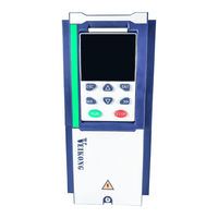
Veikong VFD500-2R2GT4B User Manual (179 pages)
High performance vector and torque control frequency inverter
Brand:
Veikong
| Category:
Inverter
| Size: 8.3 MB
Table of Contents
Table of Contents
2
Chapter 1 Safety Information and Precautions
3
Safety Precautions
3
Precaution
4
Chapter 2 Product Information
6
Designation Rules
6
Porduct Series Instruction
6
Technical Specification
9
Chapter 3 Product Appearance and Installation Dimension
12
Product Appearance and Installation
12
Product Appearance
12
Appearance and Mounting Hole Dimension
15
Removal and Installation of Cover and Inlet Plate
20
Wiring
23
Standard Wiring Diagram
23
Main Circuit Terminals
24
Terminal Screws and Wiring Specifications
26
Cautions for Main Circuit Wiring
27
Control Circuit Terminal
28
EMC Question and Solution
34
Chapter 4 Operation and Display
36
LED Instruction of Operation and Display
36
Display Hierarchy and Menu Mode
37
Digital Tube Display
38
Test Run
39
Chapter 5 Function Code Table
40
Chapter 6 Fault Diagnosis and Solution
127
Chapter 7 Selection Guide of Inverter Accessory
133
Selection Guide of Braking Component
134
PG Card Type
134
Extension Card
137
Chapter 8 Daily Maintenance of Frequency Inverters
141
Daily Maintenance
141
Regular Inspection
141
Wearing Parts Replacement
141
Warranty Items
142
Appendix A Modbus Communication Protocol
143
Appendix B Profinet Communication Card Usage Instructions
151
Advertisement
Veikong VFD500-2R2GT4B Operation Manual (111 pages)
High Performance vector and torque
Brand:
Veikong
| Category:
Controller
| Size: 3.6 MB
Table of Contents
Table of Contents
3
Chapter 1 Safety Information and Precautions
4
Contactor Using
5
Lightning Impulse Protection
5
Precaution
5
Altitude and Derating Use
6
Output Filtering
6
Power Input
6
The Scope of Application
6
Designation Rules
7
Product Series Instruction
7
Chapter 2 Product Information
7
Technical Specifications
8
Appearance and Mounting Hole Dimension
10
Chapter 3 Product Appearance and Installation Dimension
10
1Product Appearance
10
Inverter Dimensions and Installation Dimensions
12
Removal and Installation of Cover and Inlet Plate
13
Standard Wiring Diagram
15
Main Circuit Terminals
16
Terminal Screws and Wiring Specifications
17
Cautions for Main Circuit Wiring
17
Main Circuit Cable and Screw Specifications
17
Control Circuit Terminal
18
Functional Description of VFD500 Jumper Switch
20
Analog Input Terminal Instructions
20
Switch Output Terminal Instructions
22
Communication Terminal Instructions
23
EMC Question and Solution
24
Inverter Output Cable Length and Carrier Frequency Table
25
LED Instruction of Operation and Display
26
The Name and Function of each Part of the Keyboard
26
Chapter 4 Operation and Display
26
Display Hierarchy and Menu Mode
27
Standard Mode
27
User-Difined Mode
27
Digital Tube Display
28
Binary Data Display
28
Parameter Attribute Identification
28
Specific Symbol
28
Test Run
29
Trial Run Flow Chart
29
Chapter 5 Function Code Table
30
00Group Basic Function
31
01Group Frequency Source Selction
33
02 Group Start and Stop Control
38
03 Group Ramp and S Curve
40
04 Group Analog and Pulse Input
42
05 Group Analog and Pulseoutput
46
06 Group Digital Input
47
07 Group Digital Output
50
08Group Digital Output Setting
52
10 Group Encoder Type
54
11 Group Motor 1 Parameter
55
12 Group Motor 1 VF Control Parameter
57
13 Group Motor 1 Vector Control
59
14 Group Torque Control
60
16 Group Energy Saving Control Parameter
61
20 Group User-Defined Function Code Menu
62
21 Group Keypad and Display Group
63
22 Group AC Drive Data and Configuration
65
23 Group Drive Protection Function Setting
67
24 Group Motor Protection Parameter
70
25 Group Fault Tracking Parameter
72
26 Group Fault Recording Parameter
72
27 Group Monitoring Parameter
74
30 Group Modbus Communication Parameter
75
40 Group PID Function
77
41 Group Sleeping Function
81
42 Group Simple PLC
82
44 Group Variable Selector and Logic Block
86
45 Group Multi-Functional Counter
90
60 Group Motor 2 Basic Parameter
91
Chapter 6 Fault Diagnosis and Solution
93
Chapter 7 Selection Guide of Inverter Accessory
98
Selection Guide of Braking Component
98
Selection of Braking Units
98
Selection Power of Braking Resistor
98
PG Card Type
99
Incremental Pg
99
Open Collector Type, Push-Pull Output Type Encoder Wiring
100
Differential Output Encoder Wiring
100
Resolver PG Card
101
IO Extension Card
101
Chapter 8 Daily Maintenance of Frequency Inverters
103
Regular Inspection
103
Wearing Parts Replacement
103
Warranty Items
104
Appendix A Modbus Communication Protocol
105
CRC Check
108
Register Address Distribution
108
The Inverter Acts as a Modbus Master
109
Advertisement
Related Products
Veikong VFD500 Series
Veikong VFD500-R75GT4B
Veikong VFD500-1R5GT4B
Veikong VFD500-5R5G/7R5PT4B
Veikong VFD500-011G/015PT4B
Veikong VFD500-015G/018PT4B
Veikong VFD500-3R7G/5R5PT4B
Veikong VFD500-022G/030PT4B
Veikong VFD500-018G/022PT4B
Veikong VFD500-045G/055PT4
Veikong Categories
Inverter
Controller
Keyboard
More Veikong Manuals
Login
Sign In
OR
Sign in with Facebook
Sign in with Google
Upload manual
Upload from disk
Upload from URL