Table of Contents
Advertisement
Quick Links
Advertisement
Table of Contents

Related Manuals for Veikong VFD530


Summary of Contents for Veikong VFD530
- Page 1 Operation user manual VFD530 AC drive High Performance vector and torque...
- Page 2 Preface Thank you for purchasing the VFD530 series high performance vector and torque control frequency inverter. VFD530 series drivers can drive both induction motors and permanent magnet synchronous motors. VFD530 series with advanced functions, such as high performance vector control of induction motor, user-programmable function and backstage monitoring software, variable communication and supporting multiple PG cards etc.
-
Page 3: Table Of Contents
Contents Chapter 1 Safety Information and Precautions ..................1 1.1 Safety Precautions ........................... 1 1.2 Precaution ............................2 Chapter 2 Product Information ........................4 2.1 Designation Rules ..........................4 2.2 Product series instruction ....................... 4 2.3 Technical Specifications ........................6 Chapter 3 Product appearance and Installation Dimension .............. -
Page 4: Chapter 1 Safety Information And Precautions
VFD530 high performance vector control frequency inverter user manual Chapter 1 Safety information and precautions Chapter 1 Safety Information and Precautions Safety Definitions: In this manual, safety precautions are divided into the following two categories: indicates that failure to comply with the notice will result in serious injury or even death... -
Page 5: Precaution
Chapter1 Safety information and precaution VFD530 high performance vector control frequency inverter user manual Use stage Security Level Precautions the external circuit is short-circuited, the connection is tightened, or cause damage to the drive! ➢ No part of the drive need to withstand voltage test, the product has been made before the test. - Page 6 VFD530 high performance vector control frequency inverter user manual Chapter 1 Safety information and precautions ⚫ Altitude and derating use In areas above 1000m above sea level, it is necessary to derate the inverter due to poor air quality due to poor air quality.
-
Page 7: Chapter 2 Product Information
Chapter 2 Product information VFD530 high performance vector control frequency inverter user manual Chapter 2 Product Information 2.1 Designation Rules Name plate: 2-1 Name Plate Model instruction: B means breaking units 4:380-480v three phase 2: 200-240v T:three phase Load type:G normal duty Power,2R2 means 2.2kW... - Page 8 VFD530 high performance vector control frequency inverter user manual Chapter2 production information Output current(A) Adapta Power Input Brake Model capacity current SIZE Heavy Light Motor Unit (KVA) load load (KW) Three phase: 380-480V,50/60Hz VFD530-R75GT4B 0.75 VFD530-1R5GT4B SIZE A VFD530-2R2GT4B Internal VFD530-4R0G/5R5PT4B 10.5...
-
Page 9: Technical Specifications
External Description: * The built-in brake unit of this model is optional. Take 30kW as an example. The model without brake unit is VFD530-030G/037PT4, and the model with brake unit is VFD530-030G/037PT4B Technical Specifications Table 2-2 VFD530 Technical Specifications Item... - Page 10 VFD530 high performance vector control frequency inverter user manual Chapter2 production information Light load application:60S for 120% of the rated current V/f control Control mode Sensorless flux vector control without PG card(SVC) Sensor speed flux vector control with PG card (VC) Operating mode Speed control、Torque control(SVC and VC)...
- Page 11 Chapter 2 Product information VFD530 high performance vector control frequency inverter user manual Incremental Encoder Interface Card (Differential Output and Open PG card Collector), Rotary Card ,frequency division signal pg card Standard: 5 digital input terminals, one of which supports high-speed pulse input up to 50kHz;...
-
Page 12: Chapter 3 Product Appearance And Installation Dimension
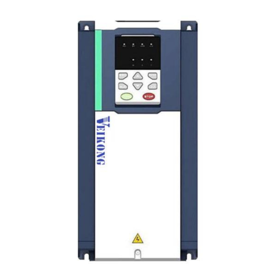
VFD530 high performance vector control frequency inverter user manual Chapter3 Product appearance and wiring Chapter 3 Product appearance and Installation Dimension Product appearance and installation 3.1.1 Product appearance Fan cover Keypad Front cover cover Back cover Name plate Line board... - Page 13 Chapter3 product appearance and wiring VFD530 high performance vector control frequency inverter user manual 3-1-3 110kw-250kw - 10 -...
- Page 14 VFD530 high performance vector control frequency inverter user manual Chapter3 Product appearance and wiring 3-1-4 110KW-250KW (With bottom base) - 11-...
-
Page 15: Appearance And Mounting Hole Dimension
◆Keypay and keypad support size The dimensions of the VFD530 series keypad are shown in Figure 3-1. When installing the keypad on the outside of the control cabinet, use the two screws on the back of the keypad to fix it (right side of Figure 3-1). - Page 16 VFD530 high performance vector control frequency inverter user manual Chapter3 Product appearance and wiring M3 screw X2 depth 8mm (for mounting to the control cabinet) Diagram 3-2 Keypad dimension If you want to mount keyboard on control cabinet (to prevent the keypad from protruding toward the outside of the control cabinet), use a keypad Bracket.
- Page 17 Chapter3 product appearance and wiring VFD530 high performance vector control frequency inverter user manual Figure 3-4 Keypad support installation diagram and control cabinet processing dimensions ◆Inverter dimensions and installation dimensions Figure 3-5 SIZE A to SIZE C(0.75KW-15KW) Dimension Figure 3-6 SIZE D~G(18.5KW-90KW) Dimension...
- Page 18 VFD530 high performance vector control frequency inverter user manual Chapter3 Product appearance and wiring Figure 3-7 SIZE H~J(110KW-250KW) Dimension Note: SIZE H~SIZE J (110kw-200kw) standard model without reactor and bottom base Reactor and bottom base for option Figure 3-8 SIZE K~J(280KW-315KW) Dimension...
- Page 19 Chapter3 product appearance and wiring VFD530 high performance vector control frequency inverter user manual Figure 3-9 SIZE K~O(315KW-710KW) Dimensions Table 3-1 VFD530 series appearance and installation dimension Appearance and installation dimension(mm) SIZE Mounting Φd screws 0.75KW-4KW 206.5 ø5.0 M4X16 5.5KW-7.5KW 239.5...
-
Page 20: Removal And Installation Of Cover And Inlet Plate
VFD530 high performance vector control frequency inverter user manual Chapter3 Product appearance and wiring Remarks: (1) B2 and H2 are the installation dimensions when the reactor base is included. (2) Φd is the diameter of the installation screw hole of the whole machine. - Page 21 Chapter3 product appearance and wiring VFD530 high performance vector control frequency inverter user manual ◆ SIZE D-G(18.5KW-90KW) Removal and installation of cover: Removal steps Installation steps ○ ○ ○ ○ ○ ○ ① Unscrew the two screws at the bottom of the bottom ①...
- Page 22 VFD530 high performance vector control frequency inverter user manual Chapter3 Product appearance and wiring ② buckle the top of the cover ①Plug in the keyboard line ③Tighten the screws at the bottom of the cover 110kw and above are door-open style...
-
Page 23: Wiring
Chapter3 product appearance and wiring VFD530 high performance vector control frequency inverter user manual 3.2 Wiring 3.2.1 Standard wiring diagram Braking Resistor breaker contactor R/L1 3 phase AC input S/L2 380V~ 50/60Hz T/L3 Main circuit Control circuit PG card RS485 port... -
Page 24: Main Circuit Terminals
VFD530 high performance vector control frequency inverter user manual Chapter3 Product appearance and wiring 3.2.2 Main Circuit Terminals Figure 3-11 SIZE A~SIZE C(0.75kw-15kw) Main Circuit Terminal Figure 3-12 SIZE D 18.5kw-22kw main circuit terminal block diagram Figure 3-13 SIZE E 30kw-37kw (LEFT) -
Page 25: Terminal Screws And Wiring Specifications
Chapter3 product appearance and wiring VFD530 high performance vector control frequency inverter user manual Figure 3-15 110kw-250kw Main Circuit Terminal Blocks Figure 3-16 280kw-400kw Main Circuit Terminal Blocks Table 3-17 Function description of the main circuit terminal of the inverter... - Page 26 VFD530 high performance vector control frequency inverter user manual Chapter3 Product appearance and wiring Power terminal Ground terminal Tightening Cable Cable Model number Tightening Screw torque diameter screw diameter torque(Nm) (Nm) (mm ) (mm ) VFD530-R75GT4B VFD530-1R5GT4B VFD530-2R2GT4B VFD530-4R0G/5R5PT4B VFD530-5R5G/7R5PT4B...
-
Page 27: Cautions For Main Circuit Wiring
Chapter3 product appearance and wiring VFD530 high performance vector control frequency inverter user manual Cautions for Main Circuit Wiring 3.2.4 (1) Power Supply Wiring ◆ It is forbidden to connect the power cable to the output terminal of the inverter. Otherwise, the internal components of the inverter will be damaged. -
Page 28: Control Circuit Terminal
VFD530 high performance vector control frequency inverter user manual Chapter3 Product appearance and wiring 3.2.5 Control Circuit Terminal Jumper switch AI1 AI2 AO1AO2 PE1 PE2 +10V 485+ T1/A T1/B T1/C 485- +24V T2/A T2/B T2/C Diagram 3-19 VFD530 control circuit terminal... - Page 29 Chapter3 product appearance and wiring VFD530 high performance vector control frequency inverter user manual Table 3-20 VFD530 control circuit terminal instruction Terminal Terminal Type Terminal function description Symbol Name 10.10V±1% Maximum output current:10mA,it provides power +10V Input voltage supply to external potentiometer with resistance range of:1KΩ~51KΩ...
- Page 30 VFD530 high performance vector control frequency inverter user manual Chapter3 Product appearance and wiring Terminal Terminal Type Terminal function description Symbol Name terminal Pulse input frequency input:0~50KHz /High-speed Voltage range:10V~30V pulse input Optocoupler isolation Open collector Voltage range:0V~24V output Current range:0mA ~50mA...
- Page 31 Chapter3 product appearance and wiring VFD530 high performance vector control frequency inverter user manual switch configuration are shown in the following figure: Voltage input Current input Figure 3-22 Analog input terminal wiring diagram The AO1 and AO2 terminals support the voltage output (0~10V) and the current output (0~20mA). They are selected by jumpers “AO1”...
- Page 32 VFD530 high performance vector control frequency inverter user manual Chapter3 Product appearance and wiring NOTE(3) A:By internal 24V with NPN mode B:By internal 24V with PNP mode External +24V +24V VFD530 controller (PNP type) NOTE(3) Y1~Y7 HDI(DI5) C:NPN mode uses external +24V power supply D:PNP mode uses external +24V power supply...
- Page 33 Chapter3 product appearance and wiring VFD530 high performance vector control frequency inverter user manual 1. If the output of the external controller is a relay contact, it can be regarded as an NPN or PNP type. The "0V" or "VCC" of the external controller in the above figure can be regarded as the common terminal of the relay.
-
Page 34: Emcquestion And Solution
VFD530 high performance vector control frequency inverter user manual Chapter3 Product appearance and wiring 3-26 Single inverter RS485 directly communicates with the host computer 485+ 485- 485+ 485- 485+ 485- 485+ 485- VFD530 VFD530 VFD530 3-16Multiple inverter RS485 is connected to the host computer for communication 3.3 EMCquestion and solution... - Page 35 Chapter3 product appearance and wiring VFD530 high performance vector control frequency inverter user manual Correct incorrect 3-27-1 Ground wire connection diagram ➢ Frequency converter to motor cable length and carrier frequency to maintain the appropriate relationship When the cable between the inverter and the motor is long, due to the influence of distributed capacitance, it is easy to produce electrical resonance, thus generating a large current so that the inverter over-current protection.
-
Page 36: Chapter 4 Operation And Display
Chapter 4 Operation and display VFD530 high performance vector control frequency inverter user manual Chapter 4 Operation and display 4.1 LED Instruction of operation and display LED keyboard consists of 5 digital tubes, 7 lights, 8 keys and a potentiometer; can be used to set the parameters, status monitoring and operation control, LED keyboard shape as shown in Figure 4-1:... -
Page 37: Display Hierarchy And Menu Mode
4.2 Display hierarchy and menu mode VFD530 digital keyboard display is divided into four layers, from top to bottom are: monitoring status, menu mode selection status, function code selection status, parameter editing / viewing status, as shown in Figure 4-2. In the menu mode selection status, press 【UP】... -
Page 38: Digital Tube Display
Chapter 4 Operation and display VFD530 high performance vector control frequency inverter user manual If visiting access (r00.01) is the end user (in the state of user password lock), then only some function code can be accessed. ◆ User-difined mode(-USr-)... -
Page 39: Test Run
VFD530 high performance vector control frequency inverter user manual Chapter 4 Operation and display ◆ Parameter attribute identification Editable parameters The leftmost LED displays "P"; the leftmost LED of the read-only parameter displays "r", as shown below. ◆ Specific symbol In some cases, the digital tube will display a specific symbol. - Page 40 Chapter 4 Operation and display VFD530 high performance vector control frequency inverter user manual start Follow the instructions in Chapter 3 to install the inverter and wire it Make sure the power cable, motor cable and brake unit are connected...
-
Page 41: Chapter 5 Function Code Table
VFD530 high performance vector control frequency inverter user manual Chapter 5 Function code Chapter 5 Function Code Table The following is the VFD530 parameter distribution list: Classification Parameter group Page 00:Basic function Page 39 01:Frequency source selection Page 41 02:Start and stop... - Page 42 Chapter 5 Function code VFD530 high performance vector control frequency inverter user manual Function Parameter name Description Default Property code 00Group Basic Function 0 ~ 65535 ➢ No user password status after power-on (P00.01=1): The way to set a user password to lock is that...
- Page 43 VFD530 high performance vector control frequency inverter user manual Chapter 5 function code table Function Parameter name Description Default Property code 0:Speed mode 1:Torque mode ➢ If use with DI function,19:Switch between P00.05 Running mode ★ torque and speed Control and 20: torque control diabled.
- Page 44 Chapter 5 Function code VFD530 high performance vector control frequency inverter user manual Functio Parameter name Description Default Property n code 01Group frequency source selction 0:Digital setting 1:AI1 2:AI2 3:AI3(IO externsion card) 4:AI4(IO externsion card) Main frequency source 5:HDI P01.00 ★...
- Page 45 VFD530 high performance vector control frequency inverter user manual Chapter 5 function code table Functio Parameter name Description Default Property n code 4:Reserved 5:Pulse setting HDI 6:Reserved 7:Communication setting Lower limit frequency(P01.09)~maximum P01.08 Upper limit frequency 50.00Hz ☆ frequency (P01.06) P01.09...
- Page 46 Chapter 5 Function code VFD530 high performance vector control frequency inverter user manual Functio Parameter name Description Default Property n code P01.18 P01.17 P01.16 P01.15 P01.14 P01.13 Unit’digit:0 phase reference source set by 0-multi-step speed(P01.21) 1-preset frequency (P00.07) 2:AI1 3:AI2...
- Page 47 VFD530 high performance vector control frequency inverter user manual Chapter 5 function code table Functio Parameter name Description Default Property n code Priority method Description: Multispeed Multispeed Multispeed Multispeed Priority method Speed terminal 4 terminal 3 terminal 2 terminal 1...
- Page 48 Chapter 5 Function code VFD530 high performance vector control frequency inverter user manual Functio Parameter name Description Default Property n code 13/in-built plc 14 frequency(P01.06) Multiple step speed Lower limit frequency(P01.09)~maximum P01.35 0.00Hz ☆ 14/in-built plc 15 frequency(P01.06) Multiple step speed Lower limit frequency(P01.09)~maximum...
- Page 49 VFD530 high performance vector control frequency inverter user manual Chapter 5 function code table Functio Parameter name Description Default Property n code P01.43 = 1: Textile frequency Aw = P01.44 * max frequency P01.45 Jump frequency 0.0%~50.0% relative to textile frequency 0.0%...
- Page 50 Chapter 5 Function code VFD530 high performance vector control frequency inverter user manual Function Parameter name Description Default Property code 02 Group Start and stop Control 0:Direct start Inverter will start from P02.01,After P02.02,It will go to setting frequency as per S curve 1:Speed tracking/Searching...
- Page 51 VFD530 high performance vector control frequency inverter user manual Chapter 5 function code table Function Parameter name Description Default Property code DC braking is used to make the running motor stop & restart. Pre-excitation is used to establish asynchronous motor magnetic field, then start, improve the response speed.
- Page 52 Chapter 5 Function code VFD530 high performance vector control frequency inverter user manual Function Parameter name Description Default Property code fault caused by DC braking at high speed. 1.00~1.50 Over excitation braking convert some kinetic energy to motor heating by increasing motor excitation.value 1 means ineffective: value...
- Page 53 VFD530 high performance vector control frequency inverter user manual Chapter 5 function code table Function Parameter name Description Default Property code 1:Speed tracking for frequency at stop 2:Speed tracking for grid frequency Ten’s digit:direction choosing 0:only search at given frequency direction 1:search on the other direction when failed for...
- Page 54 Chapter 5 Function code VFD530 high performance vector control frequency inverter user manual Function Parameter Description Default Property code name 03 Group Ramp and S curve Acceleration and 0:linear P03.00 deceleration 1:S curve A ★ curve selection 2:S curve B Acceleration and deceleration curve, also known as "Ramp Frequency Generator (RFG)", is used to smooth the frequency...
- Page 55 ☆ on model The VFD530 provides four groups of acceleration and deceleration time. The actual acceleration / deceleration time can be selected by different methods such as DI terminal, output frequency and PLC running segments. Several methods can not be used at the same time. Factory default is to use acceleration / deceleration time 1.DI terminal select acceleration and deceleration time of the mapping table is as follows::...
- Page 56 Chapter 5 Function code VFD530 high performance vector control frequency inverter user manual Function Parameter Description Default Property code name begin time S-curve P03.14 Deceleration SAME AS P03.11 0.50s ☆ Arrival time Accel and Deceltime 0:Maximum frequency P03.15 ★ frequency 1:Motor rated frequency...
- Page 57 VFD530 high performance vector control frequency inverter user manual Chapter 5 function code table Function Parameter Description Default Property code name 2:Curve C 3:Curve D Ten’unit:when input signal lower than minimum input 0:equal to minimum input 1:equal to 0.0% P04.08 AI1 filter time 0.000s~10.000s...
- Page 58 Chapter 5 Function code VFD530 high performance vector control frequency inverter user manual Function Parameter Description Default Property code name 3:Curve D Ten’unit:when input signal lower than minimum input 0:equal to minimum input 1:equal to 0.0% AI4(option card) P04.20 0.000s~10.000s 0.100s...
- Page 59 VFD530 high performance vector control frequency inverter user manual Chapter 5 function code table Function Parameter Description Default Property code name Curve C vertical -100.0%~ P04.32 0.0% ☆ axis 1 100.0% Curve C horizontal P04.31~ P04.33 3.00V ☆ axis 2 P04.35...
- Page 60 Chapter 5 Function code VFD530 high performance vector control frequency inverter user manual 05 Group Analog and Pulse output Actual output Pulse r05.00 0.00kHz~50.00kHz ● frequency 0:Common numeric output (DO2 P07.02) P05.01 HDO Pulse Output type ☆ 1:high frequency pulse output (Hdo) 0:Running frequency(0~max frequency)...
- Page 61 VFD530 high performance vector control frequency inverter user manual Chapter 5 function code table selection P05.11 AO2 output offset -100.0%~100.0% 0.0% ☆ P05.12 AO2 gain -10.00~10.00 1.00 ☆ The output error of AO2 can be corrected by P05.11 and P05.12, or the mapping relationship between signal source and actual output can be changed.
- Page 62 Chapter 5 Function code VFD530 high performance vector control frequency inverter user manual frequency pulse input 32:Switch main frequency source to DI7 Numeric input function communication setting P06.07 ★ (option card) 33:Switch auxiliary frequency source to numeric frequency setting 34:Accel and Decel time terminal 1 35:Accel and Decel time termina2...
- Page 63 VFD530 high performance vector control frequency inverter user manual Chapter 5 function code table Thousand’s digit: VDI4 input source 0~F: P06.36 specifies the bit0~bit15 of the parameter Define as per bit :Disable;1:Enable Bit0-bit11:DI1-DI12 H0000000 P06.18 DI Forcing function Bit12-bit15:VDI1-VDI4 ★...
- Page 64 Chapter 5 Function code VFD530 high performance vector control frequency inverter user manual Three-line mode -line mode Figure 3: Figure 4:Three Two-line mode 1: K1 is closed, the drive is running forward, K2 closed reverse operation, K1, K2 at the same time closed or disconnected, the inverter stops running.
- Page 65 VFD530 high performance vector control frequency inverter user manual Chapter 5 function code table Bit0:DO1 Bit1:D02 Bit2:relay1, Bit 3:relay 2 Bit4: DO3;Bit5: DO4 Bit6: DO5; Bit7: DO6 Bit8: VDO1;Bit9: VDO2 0:No function 1:READY 2:RUN DO1 Output terminal 3:Error1(All fault P07.01 ☆...
- Page 66 Chapter 5 Function code VFD530 high performance vector control frequency inverter user manual 39:Logic unit 4 output 40:Delaying unit 1 output DO5 Output terminal 41:Delaying unit 2 output P07.07 ☆ function group(IO card) 42: Delaying unit 3 output 43: Delaying unit 4 output...
- Page 67 VFD530 high performance vector control frequency inverter user manual Chapter 5 function code table 08 Group Digital output setting Frequency detection value P08.00 0.00Hz~maximum frequency(P01.06) 50.00Hz ☆ (FDT1) Frequency detection P08.01 0.0%~100.0% FDT1 5.0% ☆ hysteresis 1 Frequency detection value P08.02...
- Page 68 Chapter 5 Function code VFD530 high performance vector control frequency inverter user manual Zero speed detection P08.09 0.00H~5.00Hz 0.25Hz ☆ amplitude Zero current detection P08.10 0.0%~100.0% rated motor current 5.0% ☆ level 0.000~30.000s 0.000~30.000s Zero current detection Notice:When output current≤P08.10 and P08.11...
- Page 69 VFD530 high performance vector control frequency inverter user manual Chapter 5 function code table - 66 -...
- Page 70 Chapter 5 Function code VFD530 high performance vector control frequency inverter user manual 10 Group encoder type 0: ABZ 1: ABZUVW P10.01 Encoder type 2: Rotary/resolver ★ 3: sin/cos encoder Consult factory when need PG card ➢ 1~65535 P10.02 Encoder line number 1024 ★...
- Page 71 VFD530 high performance vector control frequency inverter user manual Chapter 5 function code table 0 ~ 4*encoder pulse number-1 r10.14 Z pulse marking value (it is used to monitor encoder slipping and AB ● being disturbed ) It is used to monitor the current UVW level of r10.15...
- Page 72 Chapter 5 Function code VFD530 high performance vector control frequency inverter user manual 11 Group Motor 1 Parameter 0:AC asynchronous motor P11.00 Motor type ● 1:Synchronous motor 0.1kW~800.0kW ➢ when power is less than 1kw ,0.75kw set to 0.8 as per round up principle ,0.55kw motor set 0.6...
- Page 73 VFD530 high performance vector control frequency inverter user manual Chapter 5 function code table speed. Before rotating self-learning, please make sure that the back-EMF (P11.22) of the synchronous motor is within ±20% of the actual value. 3 Encoder self-learning When the ten’digit is set to 0, the motor rotates slowly and can learn from P10.03 ~ P10.06.
- Page 74 Chapter 5 Function code VFD530 high performance vector control frequency inverter user manual 12 Group Motor 1 VF control parameter 0:linear VF 1:Multi-point VF 2:VF to the 1.3 P12.00 VF curve 3:1.7 power ★ 4:2.0 power 5:VF complete separation 6:VF Half separation ➢...
- Page 75 VFD530 high performance vector control frequency inverter user manual Chapter 5 function code table Multi-point VF Frequency multi-point VF curve F1(P12.03)~multi-point P12.05 50.00Hz ☆ 1(F2) VF curve F3(P12.08) P12.06 Multi-point VF Voltage 2(V2) 0.0%~100.0% 100.0% ☆ Multi-point VF Frequency P12.07 multi-point VF curveF2(P12.05)~600.00Hz...
- Page 76 Chapter 5 Function code VFD530 high performance vector control frequency inverter user manual frequency of the motor 0:ineffective Current limit function 1:only adjust output voltage(Current P12.15 ★ selection limiting for general VF separation) 2:adjust output frequency P12.16 Current limit level 20%~180% drive rated current...
- Page 77 VFD530 high performance vector control frequency inverter user manual Chapter 5 function code table gain Pressure drop compensation P12.44 0.001s~1.000s 0.010s ☆ time - 74 -...
- Page 78 Chapter 5 Function code VFD530 high performance vector control frequency inverter user manual 13 Group Motor 1 vector control Speed Proportional Gain P13.00 0.1~100.0 12.0 ☆ ASR_P1 Speed Integral Time P13.01 0.001s~30.000s 0.200s ☆ constant ASR_T1 Speed Proportional Gain P13.02 0.1~100.0...
- Page 79 VFD530 high performance vector control frequency inverter user manual Chapter 5 function code table Ten’unit:Electric torque limit source Same as unit’digit P13.07 Electric torque limit 0.0%~300.0% 160.0% ☆ P13.08 Upper limit of brake torque 0.0%~300.0% 160.0% ☆ Units: Electric power limit selection...
- Page 80 Chapter 5 Function code VFD530 high performance vector control frequency inverter user manual 14 Group Torque control 0:Digital setting(P14.01) 1:AI1 2:AI2 Torque control input P14.00 3:AI3(IO expansion board) ★ source 4:AI4(IO expansion board) 5:HDI 6:Communication -200.0~200.0% The torque reference greater than 0 indicates that the direction of the torque is the same as P14.01...
- Page 81 VFD530 high performance vector control frequency inverter user manual Chapter 5 function code table value, enter the speed mode, and the inverter will limit the speed to within the speed limit value as much as possible. P14.10 Static friction torque 0.0%~50.0%...
- Page 82 Chapter 5 Function code VFD530 high performance vector control frequency inverter user manual we are more energy efficient. Energy savings can be achieved when it is light loads or load changes so slow 17 Group synchronous motor control Initial position identification 0: Pulse testing P17.00...
- Page 83 VFD530 high performance vector control frequency inverter user manual Chapter 5 function code table 20 Group User-defined function code menu User-defined function P20.00 00.00 ☆ code 0 User-defined function code P20.01 00.00 ☆ User-defined function code P20.02 00.00 ☆ User-defined function code P20.03...
- Page 84 Chapter 5 Function code VFD530 high performance vector control frequency inverter user manual User-defined function code P20.22 00.00 ☆ User-defined function code P20.23 00.00 ☆ User-defined function code P20.24 00.00 ☆ User-defined function code P20.25 00.00 ☆ User-defined function code P20.26...
- Page 85 ☆ display parameter option VFD530 digital keyboard monitoring interface supports up to 4 monitoring volume. Monitoring variables in running status and monitoring variables in stop status are set by P21.11 and P21.12, respectively. Press 【SHIFT】 key on the keyboard to switch the monitoring volume from low to high of P21.11 or P21.12, Encountered "0"...
- Page 86 Chapter 5 Function code VFD530 high performance vector control frequency inverter user manual 27.03), press the 【SHIFT】 key on the keyboard to switch between the two monitors, as shown below. The rules for running the monitoring interface are the same as the shutdown monitoring interface, and will not be repeated Unit’s digit: quick editing function selection...
- Page 87 VFD530 high performance vector control frequency inverter user manual Chapter 5 function code table 22 Group AC drive data and configuration Depend on drives power ≤7.5kW: 1kHz~12.0kHz 11kW~45kW: 1kHz~8kHz ≥55kw: 1kHz~4kHz The carrier frequency can be reduced when it came like following phenomenon:...
- Page 88 Chapter 5 Function code VFD530 high performance vector control frequency inverter user manual 0.00Hz~600.00Hz When the carrier frequency is adjusted according to the output Carrier frequency switching P22.05 frequency, the carrier frequency set by 50.00Hz ☆ point2 P22.03 is used when the output frequency is higher than this set value.
- Page 89 VFD530 high performance vector control frequency inverter user manual Chapter 5 function code table W,For closed loop control, you need to re- rotate the self-learning to confirm the encoder direction) 0:Effective when running Cooling method (fan P22.14 1:Forced control( effective when power on) ☆...
- Page 90 Chapter 5 Function code VFD530 high performance vector control frequency inverter user manual 23 Group Drive protection function setting ➢ Unit’digit :Overvoltage stall control 0:overvoltage stall disabled 1:overvoltage stall enabled 2:overvoltage stall enabled self-adjustable ➢ The over-voltage stall function limits the amount of...
- Page 91 VFD530 high performance vector control frequency inverter user manual Chapter 5 function code table value P23.11 Over-speed detection time 0.0s~30.0s0.:shielding 1.0s ☆ Detection value of too P23.12 0.0%~100.0%(motor rated frequency) 20.0% ☆ large speed deviation Detection value of too 0.0s~30.0s P23.13...
- Page 92 Chapter 5 Function code VFD530 high performance vector control frequency inverter user manual 2: Stop as per stop mode Ten’unit: EEPROM fault 0: Coast to stop 1: Fast stop 2: Stop as per stop mode 3: Continue to run Hundred’s unit: PG card fault(reserved)
- Page 93 VFD530 high performance vector control frequency inverter user manual Chapter 5 function code table 24 Group motor Protection parameter 0.20~10.00 Motor overload protection The larger the value, the longer the allowable P24.00 1.00 ☆ gain overload operation, and the higher the risk of motor overheating damage.
- Page 94 Chapter 5 Function code VFD530 high performance vector control frequency inverter user manual 50%~100%, When the overload accumulation degree is Motor overload warning greater than this value, the P07 group DO P24.03 ☆ factor terminal output function code"26”(Motor overload warning) is selected and output valid signal Unit’digit:Motor 1 protection selection...
- Page 95 VFD530 high performance vector control frequency inverter user manual Chapter 5 function code table 25 Group Fault tracking parameter Current fault - see detail chapter 6 fault diagnosis and ● r25.00 type solution Output ● r25.01 frequency at Unit:0.01Hz fault Output current ●...
- Page 96 Chapter 5 Function code VFD530 high performance vector control frequency inverter user manual frequency at fault Output current Unit:0.1A ● r26.02 at fault Bus voltage at ● r26.03 fault Unit:V Running mode ● r26.04 See Parameter r27.10 status 1at fault Input terminal Bit0~Bit6 corresponds to DI1~DI7...
- Page 97 VFD530 high performance vector control frequency inverter user manual Chapter 5 function code table Working time at r26.22 ● fault Accumulated ● r26.23 working time atfault 27 Group Monitoring parameter Running r27.00 It can set unit as per Parameter P21.07 ●...
- Page 98 Chapter 5 Function code VFD530 high performance vector control frequency inverter user manual Bit14:overvoltage stalladjustment:0-no ;1-yes Bit15:undervoltage stall adjustment :0-no;1- Bit0~1:current command source:0- keypad;1-terminal ;2-communicatoin Bit2~3:motor option:0-motor 1;1-motor 2 Drives running ● r27.11 Bit4~5:current motor control:0-VF;1-SVC;2- mode status 2 Bit6~7:current running mode:0-speed;1- torque;2-position...
- Page 99 VFD530 high performance vector control frequency inverter user manual Chapter 5 function code table 3: 1-8-N-2 (1 star bit+8 data bits+2 stop bits) 4: 1-8-E-2 (1 star bits+8 data bit+1 even parity+2 stop bits) 5: 1-8-0-2 (1 start bit +8 data bits+1 odd parity+2 stop...
- Page 100 Chapter 5 Function code VFD530 high performance vector control frequency inverter user manual speed unit 2: 1Rpm Some units of specific communication registers can be set by this parameter. See Appendix A for details. When the format of the received frame is a...
- Page 101 (P), integral (I) and differential (D) operation, adjust the inverter output frequency, etc., to achieve closed-loop system, the controlled amount Stable at the target value. VFD530 built-in process PID structure as shown below, suitable for flow control, pressure control, temperature control and tension control applications.
- Page 102 Chapter 5 Function code VFD530 high performance vector control frequency inverter user manual ineffective effective P40.07 * 100.0% / P40.05 effective ineffective P40.08 * 100.0% / P40.05 effective effective P40.09 * 100.0% / P40.05 For example: When AI1 is used as PID feedback, if the full range corresponds to 16.0kg pressure and require PID control to be 8.0kg;...
- Page 103 VFD530 high performance vector control frequency inverter user manual Chapter 5 function code table wrapup 1: PID output is negative: When the feedback signal is stronger than the PID reference value, the output frequency of the inverter will increase to balance the PID.
- Page 104 Chapter 5 Function code VFD530 high performance vector control frequency inverter user manual integral adjustment on the deviation of PID feedback and reference. If the PID feedback changes 100% during the time, the adjustment of integral adjustor (ignoring proportional effect differential effect) is the Max.
- Page 105 VFD530 high performance vector control frequency inverter user manual Chapter 5 function code table deviation absolute value between given and feedback is bigger than P40.25 (PID parameter switching deviation 2), PID parameter selection is group 2. When the deviation absolute value between given and feedback is between P40.24 and P40.25, PID parameter is the linear interpolation of two groups PID...
- Page 106 Chapter 5 Function code VFD530 high performance vector control frequency inverter user manual shown in the diagram below, PID adjustor stops to work during the deviation limit. Set the function properly to adjust the accuracy and stability of the system.
- Page 107 VFD530 high performance vector control frequency inverter user manual Chapter 5 function code table 41 Group Sleeping function Unit’s digit: sleep mode selection 0:no sleep function 1:sleep by frequency 2:AI1 sleep (AI1 as pressure feedback) 3:AI2 sleep(AI2 as pressure feedback)
- Page 108 Chapter 5 Function code VFD530 high performance vector control frequency inverter user manual frequency When selecting frequency sleep and frequency wake-up, it must be set by P41.01 < P41.02. When the frequency source is PID setting, and the frequency wake-up must be set to PID shutdown operation: P40.39 = 1.
- Page 109 VFD530 high performance vector control frequency inverter user manual Chapter 5 function code table stage after restart and keep the remaining running at the setting frequency. PLC running P42.04 1~60000 ☆ times 0.0~6553.5 unit depend on P42.21 PLC step 1 Notice:Running time do not conclude P42.05...
- Page 110 Chapter 5 Function code VFD530 high performance vector control frequency inverter user manual Unit’digit: step 1 ACCEL/DECEL time selector ten’digit: step 2 ACCEL/DECEL time selector Hundred’s: step 3 ACCEL/DECEL time PLC step 1-4 selector P42.22 ACCEL/DECEL Thousand’unit: step 4 ACCEL/DECEL time 0000 ☆...
- Page 111 0 means invalid, 1 means valid. VFD530 inverter built-in 4 delay unit. The delay unit can collect the status of 0 ~ 15 bits of all parameters that can be viewed in the function code table, and finally output the delay unit status after delay processing and logic selection.
- Page 112 ☆ width VFD530 inbuilt 4 group variable selector,this function can be used for any two function code parameters,by selecting the comparison relationship, and output will be 1 if it meet conditions or it will be 0.Variable selector output can act as DI,VDI,virtual relay input and DO,relay.etc output.Users can easily and flexibily get logic...
- Page 113 VFD530 high performance vector control frequency inverter user manual Chapter 5 function code table Left:variable selector graph Right: hysteresis width graph Variable selector P44.06 2 input 00.00-98.99(function code index) 00.00 ☆ parameter Variable selector P44.07 00.00-98.99(function code index) 00.00 ☆...
- Page 114 9:Ref1 up and output 200ms pulse width VFD530 built-in 4 logical units. The logic unit can perform any one of 0-15 bits of any parameter 1 and any one of 0-15 bits of any parameter 2 for logic processing. The condition is true output 1, otherwise 0 is output. Logic unit output can be used as DI, VDI, delay unit and other inputs, DO, relays and other output, the user can more flexible access to the required logic.
- Page 115 VFD530 high performance vector control frequency inverter user manual Chapter 5 function code table 4:not or; 5: exclusive OR 6:Ref=1 effective;Ref2=1 ineffective 7:Ref1 up effective,Ref2 up ineffective 8:Ref1 up and signal reverse 9:Ref1 up and output 200ms pulse width Logic block 3 P44.26...
- Page 116 Chapter 5 Function code VFD530 high performance vector control frequency inverter user manual 7:Ref1 up effective,Ref2 up ineffective 8:Ref1 up and signal reverse 9:Ref1 up and output 200ms pulse width Constant setting P44.34 0~65535 ☆ Constant setting P44.35 0~65535 ☆...
- Page 117 Chapter 5 function code table VFD530 has two inbuilt counters:Counter 1 is a 32-bit multifunction counter with electronic gears; counter 2 is a 16-bit normal counter with no electronic gear function. Now take the counter 1 as an example to briefly explain its function and use, and the counter 2 will not be specified.
- Page 118 (P), integral (I) and differential (D) operation, adjust the inverter output frequency, etc., to achieve closed-loop system, the controlled amount Stable at the target value. VFD530 built-in process PID structure as shown below, suitable for flow control, pressure control, temperature control and tension control applications.
- Page 119 VFD530 high performance vector control frequency inverter user manual Chapter 5 function code table 2:AI2 3:AI3(IO expansion board) 4:AI4(IO expansion board) 5:HDI high frequency pulse 6:Communication Ten’s digit:PID Auxilary reference source(ref2)Same as Unit’s digit given P50.05 0.01~655.35 100.00 ☆ feedback range PID digital P50.06...
- Page 120 Chapter 5 Function code VFD530 high performance vector control frequency inverter user manual 8: Motor rated output torque 9: Motor rated output frequency Ten’s digit : PID feedback source2 (fdb2) Same as Unit’s digit 0:fdb1 1:fdb1+fdb2 2:fdb1-fdb2 3:fdb1*fdb2 4:fdb1/fdb2 PID feedback P50.13...
- Page 121 VFD530 high performance vector control frequency inverter user manual Chapter 5 function code table adjust is the Max. frequency (ignoring integral function and differential function). 0.01s~20.00s This parameter determines the speed of PID adjustor to carry out integral adjustment on the deviation of PID feedback and reference.
- Page 122 Chapter 5 Function code VFD530 high performance vector control frequency inverter user manual KP1, TI1, TD1; the absolute value of deviation is greater than P50.25, using KP2, TI2, TD2 parameters; the absolute value of deviation is between P50.24~P50.25, The two sets of parameters are linearly transitioned.
- Page 123 VFD530 high performance vector control frequency inverter user manual Chapter 5 function code table PID output filter P50.34 0.000~30.000s 0.010s ☆ time Detection value P50.35 of PID feedback 0.0%(no detection )~100.0% 0.0% ☆ loss ( lower limit) Detection time P50.36 of PID feedback 0.000s~30.000s...
- Page 124 Chapter 5 Function code VFD530 high performance vector control frequency inverter user manual 61 Group Motor2 parameter 61.xx same as motor 1 parameter P11.xx 62 Group Motor 2 VF control parameter 62.xx same as motor 1 VF control P12.xx 63 Group Motor 2 Vector control parameter 63.xx same as motor 2 Vector control P13.xx...
-
Page 125: Chapter 6 Fault Diagnosis And Solution
6.1 Failure and diagnosis The VFD530 inverter has perfect protection. If a fault occurs, the inverter will act according to the fault attribute. For more serious faults, the inverter will directly block the output; for general faults, it can be configured to stop or continue to operate according to the scheduled stop mode. - Page 126 VFD530 high performance vector control frequency inverter user manual Chapter6 Fault diagnosis and solutions Fault Fault Name Possible Causes Solutions Display code 1: The output circuit is grounded or 1:Eliminate external faults. short circuited. 2: Perform the motor auto- 2: Motor auto-tuning is notperformed.
- Page 127 Chapter 6 Fault diagnosis and solutions VFD530 high performance vector control frequency inverter user manual Fault Fault Name Possible Causes Solutions Display code 1:Check if the input power supply is abnormal, whether the input power terminal is loose, whether the input...
- Page 128 VFD530 high performance vector control frequency inverter user manual Chapter6 Fault diagnosis and solutions Fault Fault Name Possible Causes Solutions Display code 1. Reduce the load and check the motor and mechanical conditions. Correctly set the 1:The load is too large or the motor is motor parameters and motor blocked.
- Page 129 Chapter 6 Fault diagnosis and solutions VFD530 high performance vector control frequency inverter user manual Fault Fault Name Possible Causes Solutions Display code 1: The ambient temperature is too 1:Lower the ambient high. temperature. 2: The air filter is blocked.
- Page 130 VFD530 high performance vector control frequency inverter user manual Chapter6 Fault diagnosis and solutions Fault Fault Name Possible Causes Solutions Display code 1 check motor and mechanical 1. Motor locked condition Er.PGL Encoder offline 2. Encoder pulse setting wrong 2 set correct parameter for encoder 3.
-
Page 131: Warning Type
Chapter 6 Fault diagnosis and solutions VFD530 high performance vector control frequency inverter user manual Fault Fault Name Possible Causes Solutions Display code 1、 PID feedback<P40.35 setting value PID feedback 1、 Check PID feedback signal Er.FbL and P40.36 not zero,PID lost during 2、... - Page 132 VFD530 high performance vector control frequency inverter user manual Chapter6 Fault diagnosis and solutions Warning Reason Measure ning Display name code 1. The system is in a sleep state, and SLEEP Sleeping 1:Generally no need to pay the system will automatically start...
-
Page 133: Chapter 7 Selection Guide Of Inverter Accessory
Chapter 7 Selection guide of inverter Accessory VFD530 high performance vector control frequency inverter user manual Chapter 7 Selection Guide of inverter Accessory Selection Guide of braking component The braking resistor is used to consume the energy fed back by the motor to the inverter during braking or generating operation, so as to achieve quick braking or prevent the inverter from reporting the main circuit overvoltage fault. -
Page 134: Pg Card Type
VFD530 high performance vector control frequency inverter user manual Chapter 7 Selection guide of inverter Accessory 800W ≥ 60Ω VFD530-5R5G/7R5PT4B 1000W ≥ 60Ω VFD530-7R5G/011PT4B 1.2KW ≥ 25Ω VFD530-011G/015PT4B 1.5KW ≥ 25Ω VFD530-015G/018PT4B 2.0KW ≥ 18Ω VFD530-018G/022PT4B Built-in as option 2.5KW ≥... - Page 135 Chapter 7 Selection guide of inverter Accessory VFD530 high performance vector control frequency inverter user manual Encoder A+signal Encoder W- signal Note:UVW is Encoder used to the W+signal synchronous Encoder V- motor signal incremental Encoder encoder, no V+signal need wiring...
- Page 136 VFD530 high performance vector control frequency inverter user manual Chapter 7 Selection guide of inverter Accessory Chart 7-7 Differential output type encoder DIP switch selection The wiring of the PG card and the encoder are connected one by one according to the silkscreen.
-
Page 137: Io Extension Card
◆ MT500-IOEX1 Extension card The MT500-IOEX1 expansion card is a multi-function IO expansion card for VFD530 series inverters. It can expand 4 channels of DI, 2 channels of AI, and 4 channels of DO. Among them, , AI4 can be used as an ordinary voltage input analog quantity, and can also be used as a temperature detection input of PT100/PT1000/KTY84-130 (temperature detection is connected to PT and COM). - Page 138 VFD530 high performance vector control frequency inverter user manual Chapter 7 Selection guide of inverter Accessory +24V, PT, PLC and digital input and output 3、6、16 public terminal Provides +24V power supply to the outside, generally used as digital input and output terminal...
-
Page 139: Canopen Exentsion Card
VFD530 high performance vector control frequency inverter user manual 7.4 CANopen exentsion card The MT500-CAN1 communication card is a CANopen slave communication card for connecting VFD530 series inverters to the CANopen network. Please note that CANopen communication cannot be used simultaneously with Modbus communication. - Page 140 VFD530 high performance vector control frequency inverter user manual Chapter 7 Selection guide of inverter Accessory Figure 7-11 CANopen communication card and installation DiagramTable 7-12 CANopen communication card hardware description Graphic name Description name Function description CANopen bus terminal block, see description of...
- Page 141 Chapter 7 Selection guide of inverter Accessory VFD530 high performance vector control frequency inverter user manual Table 7-9 Function description of J1 terminal block Graphic name Description name Function description 1,4 CANH Signal line positive 2,5 CANL Signal line negative...
-
Page 142: Chapter 8 Daily Maintenance Of Frequency Inverters
VFD530 high performance vector control frequency inverter user manual Chapter 8 Maintenance Chapter 8 Daily maintenance of frequency inverters Daily maintenance Due to the influence of temperature, humidity, dust and vibration, it will lead to poor heat dissipation and component aging of frequency inverter, and results in potential failure or reducing the service life of frequency inverter. -
Page 143: Warranty Items
Chapter 8 Maintenance VFD530high performance vector control frequency inverter user manual Spared parts Replacing Damaged reasons How to check time 1, the blade has cracks 30000~ fans Bearing wear, blade aging 2 abnormal vibration, excessive 60000h noise 1, there is liquid leakage Poor input power quality, 2, the safety valve protrudes high ambient... -
Page 144: Appendix A Modbus Communication Protocol
9600bps. See parameter group set 30. Message format The VFD530 series inverter Modbus message includes the start sign, the RTU message, and the end sign。 The RTU message includes the address code, the PDU (Protocol Data Uint, the protocol data unit), and the CRC check. - Page 145 Appendix A Modbus communication protocol VFD530 high performance vector control frequency inverter user manual A.3.1 Command code 0x03Read multiple registers or status words ⚫ Request PDU Command code 1byte 0x03 initial address 2byte 0x0000~0xFFFF(high 8 bit in front) Number of registers 2byte 0x0001-0x0010 (1~...
- Page 146 VFD530 high performance vector control frequency inverter user manualAppendix A Modbus communication protocol Register Value 2* nbyte Register value high 8 bit in front,first send initial address’register value ⚫ Respond PDU Command code 1byte 0x10 Initial address 2byte 0x0000 ~ 0xFFFF( high...
- Page 147 CRC check code generation algorithm, A.6 Register address distribution The register address of VFD530 is 16-bit data, the upper 8 bits represent the function code group number, the lower 8 bits represent the group number, the upper 8 bits are sent before. The 32-bit register occupies two adjacent addresses, the even address stores the lower 16 bits, and the next address (odd address) of the even address stores the upper 16 bits.
- Page 148 VFD530 high performance vector control frequency inverter user manualAppendix A Modbus communication protocol Example 1: Function code 27.10 (drive status word 1), which The hexadecimal address is: 0x1B0A (0x1B = 27, 0x0A = 10), Decimal address: 27 × 256 + 10 = 6922.
- Page 149 Appendix A Modbus communication protocol VFD530 high performance vector control frequency inverter user manual Bit7 Bit6 Bit5 Bit4 Bit3 Bit2 Bit1 Bit0 Bit15 Bit14 Bit13 Bit12 Bit11 Bit10 Bit9 Bit8 VDO2 VDO1 2)Inverter status: Read the inverter status, see 27 groups of function codes.
- Page 150 A.8 The inverter acts as a Modbus master VFD530 can be used as a Modbus master station, it currently only supports broadcast network. When P30.09 is set as 1, master mode can be enabled. The sending frame as master station is...
- Page 151 Guidance for lifting function 1. Control circuit wiring Please pay attention to the following matters when wiring: DI3 is brake feedback, if the brake has no feedback, you don’t need to connect Relay 1 is fault signal output, and relay 2 is brake control signal output 2.
- Page 152 P11.02 Motor’s rate power P11.03 Motor’s rate voltage P11.04 Motor’s rate current P11.05 Motor’s rate frequency P11.06 Motor’s rate RPM 4、Motor self-learning 5、Open loop self-learning Set the motor parameters, if it is encoder closed-loop control, set the following encoder parameters P10.01 Type of encoder P10.02...
- Page 153 P51.02 =2.00 Up release brake frequency is 2.00hz P51.05=2.00 Down release brake frequency is2.00hz Set P59.00=2 closed-loop lifting, with encoder feedback, the following parameters are Function code description P00.06=1 Terminal control P03.01=3.00 acceleration time is 3s P03.02=3.00 deceleration time is3s P23.10=10 Turn off the overvoltage stall function P51.02 =0.20...
- Page 154 Functi Parameter name Description Default Property code Up release ☆ P51.02 0.00~10.00hz 2.00hz frequency 0.00~10.00hz,Closed loop control ☆ P51.03 Up brake frequency 2.00hz is invalid 0.0~100.0%,Closed loop control is ☆ P51.04 Up release current 10.0% invalid Down release ☆ P51.05 0.00~10.00hz 2.00hz frequency...
- Page 155 Functi Parameter name Description Default Property code frequency is lower than the zero crossing frequency 51.25 during the deceleration process, the output frequency jumps from 51.25 to - 51.25 The DI function is increased as follows 57: brake feedback input/brake feedback input 58: brake release feedback input The DO function is increased as follows 47: Brake control output...
- Page 156 ShenZhen VEIKONG Electric CO., Ltd. Factory Address: Block E01,first industrical park lingbei 5 road ,phoenix community,fuyong street , Bao'anDistrict, Shenzhen ,China TechnicalSupport Hotline: +86-0755-89587650 Web Site: www.veikong-electric.com...
Need help?
Do you have a question about the VFD530 and is the answer not in the manual?
Questions and answers