ZyXEL Communications XS3800-28 User Manual
28-port 10gbe l3 managed switch
Hide thumbs
Also See for XS3800-28:
- User manual (719 pages) ,
- Cli reference manual (407 pages) ,
- Quick start manual (2 pages)
Table of Contents
Advertisement
Quick Links
User's Guide
XS3800-28
28-port 10GbE L3 Managed Switch
Default Login Details
Out-of-Band
MGMT Port
In-Band Ports
User Name
Password
Copyright © 2022 Zyxel and/or its affiliates. All Rights Reserved.
http://192.168.0.1
http://setup.zyxel
or
http://DHCP-assigned IP
or
http://192.168.1.1
admin
1234
Version 4.80 Edition 1, 7/2022
Advertisement
Table of Contents
Troubleshooting

Subscribe to Our Youtube Channel
Related Manuals for ZyXEL Communications XS3800-28


Summary of Contents for ZyXEL Communications XS3800-28
- Page 1 User’s Guide XS3800-28 28-port 10GbE L3 Managed Switch Default Login Details Version 4.80 Edition 1, 7/2022 Out-of-Band http://192.168.0.1 MGMT Port In-Band Ports http://setup.zyxel http://DHCP-assigned IP http://192.168.1.1 User Name admin Password 1234 Copyright © 2022 Zyxel and/or its affiliates. All Rights Reserved.
- Page 2 • Nebula Control Center (NCC) User’s Guide Go to nebula.zyxel.com support.zyxel.com to get this User’s Guide on how to configure the Switch using Nebula. • More Information Go to https://community.zyxel.com/ for product discussions. Go to support.zyxel.com to find other information on the Switch XS3800-28 User’s Guide...
-
Page 3: Document Conventions
Figures in this user guide may use the following generic icons. The Switch icon is not an exact representation of your device. Switch Generic Router Wireless Router / Access Point Generic Switch Smart TV Desktop Laptop IP Camera Printer Server XS3800-28 User’s Guide... -
Page 4: Table Of Contents
Switch Setup ............................206 Syslog Setup ............................209 Time Range ............................212 PORT ..............................215 Flex Link ..............................216 Green Ethernet ........................... 220 Link Aggregation ..........................224 Link Layer Discovery Protocol (LLDP) ....................234 OAM ..............................260 XS3800-28 User’s Guide... - Page 5 RIP ................................. 520 Router Setup ............................523 Static Route ............................526 VRRP ..............................531 SECURITY .............................. 541 AAA ..............................542 Access Control ............................ 556 Classifier ............................... 566 Policy Rule ............................576 Anti-Arpscan ............................582 BPDU Guard ............................589 XS3800-28 User’s Guide...
- Page 6 Error-Disable ............................596 IP Source Guard ..........................604 DHCP Snooping ..........................609 ARP Inspection ............................ 621 Port Authentication ..........................642 Port Security ............................657 MAINTENANCE ............................ 663 Networked AV Mode ......................... 691 Troubleshooting and Appendices ....................747 Troubleshooting ..........................748 XS3800-28 User’s Guide...
-
Page 7: Table Of Contents
2.4 Mounting the Switch on a Rack ....................42 2.4.1 Installation Requirements ..................... 42 2.4.2 Precautions ..........................42 2.4.3 Attaching the Mounting Brackets to the Switch ............... 43 2.4.4 Mounting the Switch on a Rack ..................43 XS3800-28 User’s Guide... - Page 8 4.8.2 Reload the Configuration File ....................86 4.9 Log Out of the Web Configurator ....................87 4.10 Help ..............................87 Chapter 5 Initial Setup Example .........................89 5.1 Overview ............................89 5.1.1 Create a VLAN ........................89 5.1.2 Set Port VID ..........................90 XS3800-28 User’s Guide...
- Page 9 Chapter 11 IPv6 Neighbor Table.........................116 11.1 IPv6 Neighbor Table Overview ....................116 11.2 Viewing the IPv6 Neighbor Table ..................... 116 Chapter 12 MAC Table ............................118 12.1 MAC Table Overview ......................... 118 12.1.1 What You Can Do ......................118 XS3800-28 User’s Guide...
- Page 10 17.0.1 What You Can Do ......................138 17.1 System Information ........................138 17.2 Hardware Monitor (Stacking Mode) ..................142 Chapter 18 System Log............................144 18.1 System Log Overview ......................... 144 18.2 System Log ..........................144 Chapter 19 SYSTEM ..............................146 XS3800-28 User’s Guide...
- Page 11 24.6 IPv6 Global Address Setup ......................172 24.6.1 Add/Edit an IPv6 Global Address ..................173 24.7 IPv6 Neighbor Discovery Setup ....................173 24.7.1 Edit an IPv6 Neighbor Discovery ..................174 24.8 IPv6 Router Discovery Setup ...................... 175 XS3800-28 User’s Guide...
- Page 12 Switch Setup .............................206 28.1 Switch Setup Overview ......................206 28.1.1 Introduction to VLANs ....................... 206 28.2 Switch Setup ..........................206 Chapter 29 Syslog Setup .............................209 29.1 Syslog Overview .......................... 209 29.1.1 What You Can Do ......................209 XS3800-28 User’s Guide...
- Page 13 Link Layer Discovery Protocol (LLDP) .....................234 35.1 LLDP Overview ..........................234 35.2 LLDP-MED Overview ........................235 35.2.1 What You Can Do – LLDP ....................236 35.2.2 What You Can Do – LLDP MED ..................236 35.3 LLDP Local Status ........................236 XS3800-28 User’s Guide...
- Page 14 Chapter 40 Layer 2 Protocol Tunneling ......................280 40.1 Layer 2 Protocol Tunneling Overview ..................280 40.1.1 What You Can Do ......................280 40.1.2 What You Need to Know ....................280 40.2 Configuring Layer 2 Protocol Tunneling ................... 281 XS3800-28 User’s Guide...
- Page 15 44.5 IGMP Filtering Profile ........................315 44.5.1 Add IGMP Filtering Profile ....................316 44.5.2 Add IGMP Filtering Rule ....................316 44.6 IPv6 Multicast Status ........................317 44.7 MLD Snooping-proxy ........................318 44.8 MLD Snooping-proxy VLAN ....................... 318 XS3800-28 User’s Guide...
- Page 16 47.1.2 What You Need to Know ....................344 47.2 PPPoE Intermediate Agent ......................346 47.3 PPPoE IA Port ..........................348 47.4 PPPoE IA Port VLAN ........................350 47.5 PPPoE IA VLAN ..........................352 Chapter 48 Private VLAN .............................353 48.1 Private VLAN Overview ......................353 XS3800-28 User’s Guide...
- Page 17 53.3 sFlow Collector Configuration ....................373 53.3.1 Add/Edit sFlow Collector ....................374 Chapter 54 Spanning Tree Protocol ........................375 54.1 Spanning Tree Protocol Overview .................... 375 54.1.1 What You Can Do ......................375 54.1.2 What You Need to Know ....................375 XS3800-28 User’s Guide...
- Page 18 57.3 VLAN Status ..........................415 57.3.1 VLAN Details ........................416 57.4 Private VLAN Status ........................418 57.5 Configure a Static VLAN ......................419 57.5.1 Add/Edit a Static VLAN ....................419 57.6 VLAN Port Setup .......................... 422 57.7 Configure GVRP .......................... 424 XS3800-28 User’s Guide...
- Page 19 60.3 VLAN Tag Format ........................450 60.3.1 Frame Format ........................451 60.4 Configuring VLAN Stacking ....................... 451 60.5 Port-Based Q-in-Q ........................453 60.6 Selective Q-in-Q .......................... 455 60.6.1 Add/Edit Selective Q-in-Q ....................456 Chapter 61 WoL Relay ............................458 XS3800-28 User’s Guide...
- Page 20 64.9.1 Add/Edit DHCPv6 Relay ....................483 64.10 DHCPv6 Server Status ....................... 484 64.11 DHCPv6 Server Information ..................... 485 64.11.1 Add/Edit DHCPv6 Server Information ................485 64.12 DHCPv6 Prefix Delegation ....................... 486 64.12.1 Add/Edit DHCPv6 Prefix Delegation ................487 XS3800-28 User’s Guide...
- Page 21 67.5.1 Add/Edit IPv4 OSPF Redistribution ................... 512 67.6 IPv4 OSPF Virtual-Links ........................ 513 67.6.1 Add/Edit IPv4 OSPF Virtual-Links ..................514 Chapter 68 Policy Routing...........................516 68.1 Policy Route Overview ....................... 516 68.1.1 Benefits ..........................516 68.2 Configuring Policy Routing Profile ..................... 516 XS3800-28 User’s Guide...
- Page 22 72.4 VRRP Configuration Examples ....................536 72.4.1 One Subnet Network Example ..................536 72.4.2 Two Subnets Example ....................... 538 Chapter 73 SECURITY ............................541 Chapter 74 AAA ..............................542 74.1 Authentication, Authorization and Accounting (AAA) ............542 74.1.1 What You Can Do ......................542 XS3800-28 User’s Guide...
- Page 23 77.1 Policy Rules Overview ........................ 576 77.1.1 What You Can Do ......................576 77.1.2 DiffServ ..........................576 77.1.3 DSCP and Per-Hop Behavior ................... 576 77.2 Policy Rules ..........................577 77.2.1 Add/Edit a Policy Rule ...................... 577 77.3 Policy Example ..........................580 XS3800-28 User’s Guide...
- Page 24 82.1.1 What You Can Do ......................604 82.1.2 What You Need to Know ....................604 82.2 IPv4 Source Guard ........................605 82.3 IPv4 Source Guard Static Binding ..................... 605 82.3.1 Add/Edit IPv4 Source Guard Static Binding ..............607 XS3800-28 User’s Guide...
- Page 25 Chapter 85 Port Authentication ..........................642 85.1 Port Authentication Overview ....................642 85.1.1 What You Can Do ......................642 85.1.2 What You Need to Know ....................643 85.1.3 MAC Authentication ......................643 85.2 Activate IEEE 802.1x Security ..................... 644 XS3800-28 User’s Guide...
- Page 26 87.8 Restore Configuration ........................ 673 87.9 Backup Configuration ........................ 673 87.10 Auto Configuration ........................674 87.11 Erase Running-Configuration ....................675 87.12 Save Configuration ........................676 87.13 Configure Clone ........................677 87.14 Diagnostic ..........................679 87.15 Firmware Upgrade ........................683 XS3800-28 User’s Guide...
- Page 27 88.27 IGMP Snooping ......................... 721 88.28 IGMP Snooping VLAN ......................724 88.28.1 Add/Edit IGMP Snooping VLANs ................... 725 88.29 IGMP Filtering Profile ......................... 726 88.29.1 Add IGMP Filtering Profile ....................727 88.29.2 Add IGMP Filtering Rule ....................728 XS3800-28 User’s Guide...
- Page 28 89.1 Power, Hardware Connections, and LEDs ................748 89.2 Switch Access and Login ......................749 89.3 Switch Configuration ........................751 Appendix A Customer Support ..................... 752 Appendix B Common Services ...................... 757 Appendix C IPv6..........................760 Appendix D Legal Information ...................... 769 Index ..............................774 XS3800-28 User’s Guide...
-
Page 29: User's Guide
User’s Guide... -
Page 30: Getting To Know Your Switch
Switches of the same model and firmware version and allows you to remotely manage them from one switch using one single IP address. The Switch performs full layer-2 switching features and basic layer-3 routing features, such as static route, and IGMP. XS3800-28 User’s Guide... -
Page 31: License Option
(NAS) or Access Point (AP) only supports 2.5 Gigabit or 5 Gigabit connectivity, then the maximum speed potential of these devices is never reached. In addition, at the time of writing, most existing cabling is Cat 5e or Cat 6, further limiting maximum XS3800-28 User’s Guide... -
Page 32: Stacking Mode
The stackable switches can be managed from a master switch in the stack. Note: To set the Switch to Stacking mode, go to the SYSTEM > Stacking > Stacking Setup screen. XS3800-28 User’s Guide... -
Page 33: Management Modes
Nebula web portal (https://nebula.zyxel.com). See the following steps or the Switch Quick Start Guide for registering the Switch. Go to the NCC to Register the Switch Go to the Nebula web portal in one of three ways. XS3800-28 User’s Guide... - Page 34 Switch is in Cloud mode, use the Local credentials password to login. Note: The Local credentials: Password can be found in Site-wide > Configure > General settings > Device configuration in the NCC portal. See the NCC User’s Guide for more information. XS3800-28 User’s Guide...
-
Page 35: Zon Utility
The following table shows which firmware version supports ZON and Neighbor Management (Smart Connect) for each Switch. The firmware on each Switch is identified by the firmware trunk version, followed by a unique model code and release number in brackets. For example, 4.70(ABML.0) is a XS3800-28 User’s Guide... -
Page 36: Web Configurator Networked Av Mode
Switch’s port or connect other switches to the Switch. In this example, all computers can share high-speed applications on the server. To expand the network, simply add more networking devices such as switches, routers, computers, print servers, and so on. XS3800-28 User’s Guide... -
Page 37: Bridging Or Fiber Optic Uplink Example Application
You can provide a super-fast uplink connection by using a Gigabit Ethernet or SFP port on the Switch. Moreover, the Switch eases supervision and maintenance by allowing network managers to centralize multiple servers at a single location. Figure 6 Bridging or Fiber Optic Uplink Example Application XS3800-28 User’s Guide... -
Page 38: High Performance Switching Example
Shared resources such as a server can be used by all ports in the same VLAN as the server. In the following figure only ports that need access to the server need to be part of VLAN 1. Ports can belong to other VLAN groups too. XS3800-28 User’s Guide... -
Page 39: Ipv6 Support
• FTP. Use File Transfer Protocol for firmware upgrades and configuration backup or restore. See Section 87.3.1 on page 665. • SNMP. The Switch can be monitored and/or managed by an SNMP manager. See Section 26.6.1 on page 191. XS3800-28 User’s Guide... -
Page 40: Good Habits For Managing The Switch
Switch to its factory default settings. If you backed up an earlier configuration file, you would not have to totally re-configure the Switch. You could simply restore your last configuration. XS3800-28 User’s Guide... -
Page 41: Hardware Installation And Connection
• The Switches with fans are not suitable for use in locations where children are likely to be present. To start using the Switch, simply connect the power cables to turn it on. 2.3 Freestanding Installation Procedure Make sure the Switch is clean and dry. Remove the adhesive backing from the rubber feet. XS3800-28 User’s Guide... -
Page 42: Mounting The Switch On A Rack
21.5 kg. • Make sure the position of the Switch does not make the rack unstable or top-heavy. Take all necessary precautions to anchor the rack securely before installing the unit. XS3800-28 User’s Guide... -
Page 43: Attaching The Mounting Brackets To The Switch
Figure 11 Mounting the Switch on a Rack Using a #2 Philips screwdriver, install the M5 flat head screws through the mounting bracket holes into XS3800-28 User’s Guide... - Page 44 Chapter 2 Hardware Installation and Connection the rack. Note: Make sure you tighten all the four screws to prevent the Switch from getting slanted. Repeat steps to attach the second mounting bracket on the other side of the rack. XS3800-28 User’s Guide...
-
Page 45: Hardware Panels
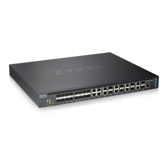
Ethernet ports support Multi-Gigabit (100 Mbps, 1 Gbps, 2.5 Gbps, 5 Gbps, and 10 Gbps). The figure below shows the front panel of the Switch. Figure 12 Front Panel: XS3800-28 The following table describes the ports. Table 5 Panel Connections... -
Page 46: Ethernet Ports
You can change transceivers or the DAC cables while the Switch is operating. You can use different transceivers to connect to Ethernet switches with different types of fiber optic connectors. • Type: SFP connection interface • Connection speed: 1 or 10 Gigabit per second (Gbps) XS3800-28 User’s Guide... - Page 47 Remove the dust plugs from the transceiver and cables (dust plug styles vary). Identify the signal transmission direction of the fiber optic cables and the transceiver. Insert the fiber optic cable into the transceiver. Figure 13 Latch in the Lock Position Figure 14 Transceiver Installation Example XS3800-28 User’s Guide...
- Page 48 Switch and transceiver. Insert the dust plug into the ports on the transceiver and the cables. Figure 16 Removing the Fiber Optic Cables Figure 17 Opening the Transceiver’s Latch Example Figure 18 Transceiver Removal Example XS3800-28 User’s Guide...
-
Page 49: Dual Personality Interfaces
• No parity, 8 data bits, 1 stop bit • No flow control 3.2 Rear Panel The following figures show the rear panels of the Switch. The rear panels contain: • Two AC power receptacles (A and B) Figure 20 Rear Panel: XS3800-28 XS3800-28 User’s Guide... -
Page 50: Grounding
Attach the other end of the ground cable to a grounding bar located on the rack where you install the Switch or to an on-site grounding terminal. Figure 22 Attach Ground Cable to Grounding Bar or On-site Grounding Terminal XS3800-28 User’s Guide... -
Page 51: Ac Power Connection
Use the following procedures to connect the Switch to a power source after you have installed it in a rack. Note: Use the included power cord for the AC power connection. Connect the female end of the power cord to the AC power socket. Connect the other end of the cord to a power outlet. XS3800-28 User’s Guide... -
Page 52: Leds
SYS (System) Green The Switch is on and functioning properly. Blinking The Switch is rebooting and performing self-diagnostic tests. The Switch is functioning abnormally. The power is off or the system is not ready or malfunctioning. XS3800-28 User’s Guide... - Page 53 Mbps through the MGMT port. The MGMT port is not connected to an Ethernet device, or the port is disabled. STACK ID The LED is showing the Stack ID number of the Switch. ID 0 means it is a standalone Switch. XS3800-28 User’s Guide...
-
Page 54: Technical Reference
Technical Reference... -
Page 55: Web Configurator
Also, you can use the ZON Utility to check your Switch’s IP address. See Section 4.3 on page 60 for more information on the ZON utility. The Login screen appears. XS3800-28 User’s Guide... - Page 56 Switch to Nebula Cloud management. Figure 25 Visit Nebula Click Login to log into the Web Configurator to manage the Switch directly. The default user name is admin and associated default password is 1234. The Select Mode screen appears. XS3800-28 User’s Guide...
- Page 57 Once you click the Finish button, the settings configured in the Setup Wizard screen will overwrite the existing settings. Otherwise, click the Exit button. If you want to open the Setup Wizard screen later, click the Wizard icon in the upper right hand corner of the Web Configurator in Networked AV mode. XS3800-28 User’s Guide...
- Page 58 If you log into the Web Configurator and select Networked AV Mode, open the screen in the Wizard > Step 2 Password to change the administrator password and SNMP community string. Click Finish on the last step of the Wizard to save your settings. Password/SNMP Setting Figure 28 Web Configurator: Warning XS3800-28 User’s Guide...
- Page 59 Save link on the top navigation panel to save your changes to the non-volatile memory when you are done configuring. Cancel Click Cancel to begin configuring this screen afresh. XS3800-28 User’s Guide...
-
Page 60: Zyxel One Network (Zon) Utility
4.3.2 Run the ZON Utility Double-click the ZON Utility to run it. The first time you run the ZON Utility, you will see if your device and firmware version support the ZON Utility. Click the OK button to close this screen. XS3800-28 User’s Guide... - Page 61 If your device is not listed here, see the device release notes for ZON Utility support. The release notes are in the firmware zip file on the Zyxel web site. Figure 31 ZON Utility Screen Select a network adapter to which your supported devices are connected. XS3800-28 User’s Guide...
- Page 62 Select a device and then use the icons to perform actions. Some functions may not be available for your devices. Note: You must know the selected device admin password before taking actions on the device using the ZON Utility icons. XS3800-28 User’s Guide...
- Page 63 This field displays an icon of the kind of device discovered. Model This field displays the model name of the discovered device. Firmware Version This field displays the firmware version of the discovered device. MAC Address This field displays the MAC address of the discovered device. XS3800-28 User’s Guide...
-
Page 64: Networked Av Mode Wizard
Networked AV mode settings, and view finished results. In order to set up your IP or DNS, please do the following. Click Wizard > Basic Settings > Next > Step 1 IP to access this screen. XS3800-28 User’s Guide... - Page 65 Enter a domain name server IP address in order to be able to use a domain name instead of an IP address. Next Click Next to show the next screen. Cancel Click Cancel to exit this screen without saving. After clicking Next, the Password screen appears. XS3800-28 User’s Guide...
- Page 66 The Get Community string is only used by SNMP managers using SNMP version 2c or lower. Set Community Enter the Set Community string, which is the password for the incoming Set- requests from the management station. The Set Community string is only used by SNMP managers using SNMP version 2c or lower. XS3800-28 User’s Guide...
- Page 67 (for example computer, NAS) to the RJ45 ports. Previous Click Previous to show the previous screen. Next Click Next to show the next screen. Cancel Click Cancel to exit this screen without saving. After clicking Next, the Summary screen appears. XS3800-28 User’s Guide...
- Page 68 This field displays the Get Community string. Set Community This field displays the Set Community string. Trap Community This field displays the Trap Community string. Networked AV – Basic Settings Networked AV This field displays the VLAN ID for the AVoIP network. VLAN XS3800-28 User’s Guide...
-
Page 69: Advanced Settings
Networked AV service to a VLAN, select and assign port role, link aggregation (trunking), and view finished results. In order to set up your IP or DNS, please do the following. Click Wizard > Advanced Settings > Step 1 IP to access this screen. XS3800-28 User’s Guide... - Page 70 Enter a domain name server IP address in order to be able to use a domain name instead of an IP address. Next Click Next to show the next screen. Cancel Click Cancel to exit this screen without saving. After clicking Next, the Password screen appears. XS3800-28 User’s Guide...
- Page 71 The Get Community string is only used by SNMP managers using SNMP version 2c or lower. Set Community Enter the Set Community string, which is the password for the incoming Set- requests from the management station. The Set Community string is only used by SNMP managers using SNMP version 2c or lower. XS3800-28 User’s Guide...
- Page 72 You must enter a different VLAN ID in the Networked AV VLAN field to be able to assign (Optional) another subnet mask that specifies the network number portion of an IP address. Select Ports and Assign a Port Role XS3800-28 User’s Guide...
- Page 73 Table 17 Wizard > Advanced Settings > Step 4 Summary LABEL DESCRIPTION Setup IP Host Name This field displays a host name. IP Interface This field displays whether the WAN interface is using a DHCP IP address or a static IP address. XS3800-28 User’s Guide...
-
Page 74: Web Configurator Layout
Click Cancel to exit this screen without saving. 4.5 Web Configurator Layout The DASHBOARD screen is the first screen that displays when you access the Web Configurator. The following figure shows the navigating components of a Web Configurator screen. XS3800-28 User’s Guide... - Page 75 You can also click the ON/OFF switch to go to the SYSTEM > Cloud Management screen and check the diagnostic messages. See Section Table 22 on page 106 for more information. This does not appear in Stacking mode. XS3800-28 User’s Guide...
- Page 76 This link takes you to a screen where you can configure the DHCP client, and a static IP address (IP address and subnet mask). IPv6 Click the link to unfold the following sub-link menu. IPv6 Status This link takes you to a screen where you can view the IPv6 table and DNS server. XS3800-28 User’s Guide...
- Page 77 This link takes you to a screen where you can configure L2PT (Layer 2 Protocol Tunneling) settings col Tunneling on the Switch. Loop Guard This link takes you to a screen where you can configure protection against network loops that occur on the edge of your network. XS3800-28 User’s Guide...
- Page 78 This link takes you to a screen where you can configure the MSTP (Multiple Spanning Tree Proto- col) settings on the Switch. Static MAC Fil- This link takes you to a screen to set up static MAC filtering rules. tering XS3800-28 User’s Guide...
- Page 79 This link takes you to a screen where you can configure the DVMRP (Distance Vector Multicast Routing Protocol) settings. IGMP This link takes you to a screen where you can enable IGMP (Internet Group Management Proto- col) on the Switch and configure the Switch as a multicast router. XS3800-28 User’s Guide...
- Page 80 This link takes you to a screen to set up broadcast filters. Errdisable This link takes you to a screens where you can view errdisable status and configure errdisable set- tings in CPU protection, errdisable detect, and errdisable recovery. XS3800-28 User’s Guide...
- Page 81 This link takes you to a screen where you can save your Switch’s configurations (settings) for later Configurati use. Auto This link takes you to a screen where you can overwrite the running configuration stored in the Configurati Switch’s RAM. XS3800-28 User’s Guide...
- Page 82 Multicast This link takes you to screens where you can view multicast group information, configure various multicast features like IGMP snooping and filtering profile, and create multicast VLANs. XS3800-28 User’s Guide...
-
Page 83: Tables And Lists
Tables have tool icons for working with table entries as shown next. You can select one or more entries, or select the check box in the heading row to select all entries. Use the tool icons to modify the selected entries. Figure 46 Working with a Table XS3800-28 User’s Guide... -
Page 84: Change Your Password
Figure 47 Working on a List 4.5.2 Change Your Password After you log in for the first time, it is recommended you change the default administrator password. Click SYSTEM > Logins to display the next screen. XS3800-28 User’s Guide... -
Page 85: Save Your Configuration
Delete the management VLAN (default is VLAN 1). Delete all port-based VLANs with the CPU port as a member. The “CPU port” is the management port of the Switch. Filter all traffic to the CPU port. Disable all ports. XS3800-28 User’s Guide... -
Page 86: Reset The Switch
Enter atlc after the “Enter Debug Mode” message. Wait for the “Starting XMODEM upload” message before activating XMODEM upload on your terminal. After a configuration file upload, type atgo to restart the Switch. XS3800-28 User’s Guide... -
Page 87: Log Out Of The Web Configurator
4.10 Help The Web Configurator’s online help has descriptions of individual screens and some supplementary information. Click the Help icon on a Web Configurator screen to view an online help description (shown as below) of that screen. XS3800-28 User’s Guide... - Page 88 Chapter 4 Web Configurator Figure 51 Online Web Help XS3800-28 User’s Guide...
-
Page 89: Initial Setup Example
In this example, you want to configure port 1 as a member of VLAN 2. Figure 52 Initial Setup Network Example: VLAN Go to the SWITCHING > VLAN > VLAN Setup > Static VLAN screen. Click Add/Edit. XS3800-28 User’s Guide... -
Page 90: Set Port Vid
Use PVID to add a tag to incoming untagged frames received on that port so that the frames are forwarded to the VLAN group that the tag defines. In the example network, configure 2 as the port VID on port 1 so that any untagged frames received on that port get sent to VLAN 2. XS3800-28 User’s Guide... -
Page 91: Configure Switch Management Ip Address
If the Switch fails to obtain an IP address from a DHCP server, the Switch will use 192.168.1.1 as the management IP address. You can configure another IP address in a different subnet for management purposes. The following figure shows an example. XS3800-28 User’s Guide... - Page 92 Switch is using a DHCP-assigned IP or static IP address. This requires your PC to be directly connected to the Switch. Go to the SYSTEM > IP Setup > IP Setup screen. Click Add/Edit. The following screen appears. XS3800-28 User’s Guide...
- Page 93 In this example, enter VLAN ID 2. This is the same as the VLAN ID you configure in the Static VLAN screen. Click Apply to save your changes back to the run-time memory. Settings in the run-time memory are lost when the Switch’s power is turned off. XS3800-28 User’s Guide...
-
Page 94: Tutorials
Connect your computer to the out-of-band management port (So you can access the Switch without affected by any IP change caused by configurations). Access the Switch through http://192.168.0.1. Log into the Switch by entering the user name (default: admin) and password (default: 1234). XS3800-28 User’s Guide... - Page 95 Go to SWITCHING > VLAN > VLAN Setup > VLAN Port Setup, and set the PVID of the ports 4, 5 and 6 to 100. This tags untagged incoming frames on ports 4, 5 and 6 with the tag 100. Click Apply. XS3800-28 User’s Guide...
- Page 96 Go to SECURITY > IPv4 Source Guard > DHCP Snooping > DHCP Snp. Port Setup. Select Trusted in the Server Trusted state field for port 4 because the DHCP server is connected to port 4. Keep ports 5 and 6 Untrusted because they are connected to DHCP clients. Click Apply. XS3800-28 User’s Guide...
- Page 97 Click Save at the top right of the Web Configurator to save the configuration permanently. 10 To check if DHCP snooping works, go to SECURITY > IPv4 Source Guard > IP Source Guard, you should see an IP assignment with the type DHCP-Snooping as shown. XS3800-28 User’s Guide...
-
Page 98: How To Use Dhcpv4 Relay On The Switch
Follow the steps below to configure port 2 as a member of VLAN 102. Access the Web Configurator through the Switch’s management port. Go to SYSTEM > Switch Setup and set the VLAN Type to 802.1Q. Click Apply to save the settings to the run-time memory. XS3800-28 User’s Guide... - Page 99 The following screen appears. Enable the switch button to set this VLAN to Active. Enter a descriptive name (VLAN 102 for example) in the Name field and enter “102” in the VLAN Group ID field. Set port 2 to be a permanent member of this VLAN by selecting Fixed in the Control field. XS3800-28 User’s Guide...
-
Page 100: Configure Dhcpv4 Relay
Follow the steps below to enable DHCP relay on the Switch and allow the Switch to add relay agent information (such as the VLAN ID) to DHCP requests. Click NETWORKING > DHCP > DHCPv4 Relay > DHCP Smart Relay. Enable the Active switch button. XS3800-28 User’s Guide... -
Page 101: Troubleshooting
Note that you can set up a DHCP server and TFTP server either on the same device or different devices. Also, make sure the Switch can communicate with the TFTP server. Note: Steps order could vary according to different programs you use. XS3800-28 User’s Guide... - Page 102 Enable the switch button in the Active field to enable auto configuration. Select DHCP in the Mode field, and enter the VLAN ID where the DHCP server belongs to in the DHCP VLAN ID field. Click Apply to save your changes. XS3800-28 User’s Guide...
- Page 103 Click the same button in the MAINTENANCE > Reboot System screen to reboot the Switch, and load the auto configuration setting as configured before. For example, if you save the auto configuration setting to Config 1, you need to click the Config 1 button in the Reboot System screen. XS3800-28 User’s Guide...
- Page 104 Check the screens to see if it is the configuration file you want to load. If it is not, go through the steps above to check your configurations. If it is, click Save at the top right corner of the Web Configurator to save the configuration permanently. XS3800-28 User’s Guide...
-
Page 105: Dashboard
Find the latest release note in: Download Library on www.zyxel.com. 7.2 DASHBOARD This screen displays general device information, system status, system resource usage, and port status. Click DASHBOARD in the navigation panel to open the following screen. XS3800-28 User’s Guide... - Page 106 Click on a port to open the port’s status panel. Use the status panel to enable/disable a port and view its basic information. For example, link speed and port utilization. In Stacking mode, this displays the port status of the slot (Switch) selected in the SLOT field. XS3800-28 User’s Guide...
- Page 107 This field displays the hardware version of the Switch. Version System MAC This field displays the MAC address of the Switch. Address Registration This is the MAC address reserved for NCC registration. Use this MAC address to register the Switch on NCC. Address XS3800-28 User’s Guide...
- Page 108 The Switch has temperature sensors that are capable of detecting and reporting if the temperature rises above the threshold. This displays the Switch’s current device temperature level. Click to go to the MONITOR > System Information screen to check the detailed information. XS3800-28 User’s Guide...
-
Page 109: Port Status
The quick links in the Quick Link section provide shortcuts to specific configuration screens. You can use the quick links to directly access the screens that you would frequently use. You can also decide which quick links to be put on the DASHBOARD screen using the Edit button. XS3800-28 User’s Guide... - Page 110 The setup panel displays after you click the Edit button. Figure 68 Quick Link Selection Select the quick links you want and click Apply. The selected quick links will be displayed in the Quick Link section on the DASHBOARD screen. XS3800-28 User’s Guide...
-
Page 111: Monitor
• ARP Table • IP Table • IPv6 Neighbor Table • MAC Table • Neighbor • Path MTU Table • Port StatusThis chapter introduces the Port Status screens. • Routing Table • System Information • System Log XS3800-28 User’s Guide... -
Page 112: Arp Table
MAC address that replied. 9.2 Viewing the ARP Table Use the ARP table to view IP-to-MAC address mappings and remove specific dynamic ARP entries. Click MONITOR > ARP Table in the navigation panel to open the following screen. XS3800-28 User’s Guide... - Page 113 This shows 0 for a static entry. Type This shows whether the IP address is dynamic (learned by the Switch) or static (manually configured in SYSTEM > IP Setup > IP Setup or NETWORKING > ARP Setup > Static ARP). XS3800-28 User’s Guide...
-
Page 114: Ip Table
• If the Switch has already learned the port for this IP address, but the destination port is the same as the port it came in on, then it filters the packet. Figure 70 IP Table Flowchart XS3800-28 User’s Guide... -
Page 115: Viewing The Ip Table
Click this button to display and arrange the data according to IP address. Click this button to display and arrange the data according to VLAN group. Port Click this button to display and arrange the data according to port number. XS3800-28 User’s Guide... -
Page 116: Ipv6 Neighbor Table
11.2 Viewing the IPv6 Neighbor Table Use this screen to view IPv6 neighbor information on the Switch. Click MONITOR > IPv6 Neighbor Table in the navigation panel to display the screen as shown. Figure 72 MONITOR > IPv6 Neighbor Table XS3800-28 User’s Guide... - Page 117 Click this button to display and arrange the data according to IPv6 address. Click this button to display and arrange the data according to MAC address. Interface Click this button to display and arrange the data according to IPv6 interface. XS3800-28 User’s Guide...
-
Page 118: Mac Table
MAC address. The Switch then learns the port that replies with the MAC address. • If the Switch has already learned the port for this MAC address, but the destination port is the same as the port it came in on, then it filters the frame. XS3800-28 User’s Guide... -
Page 119: Viewing The Mac Table
MAC forwarding table or MAC filtering table from the MAC table using this screen. Click MONITOR > MAC Table in the navigation panel to display the following screen. Figure 74 MONITOR > MAC Table XS3800-28 User’s Guide... - Page 120 This is the port from which the above MAC address was learned. In Stacking mode, the first number represents the slot and the second the port number. Type This shows whether the MAC address is Dynamic (learned by the Switch) or Static (manually entered in the SWITCHING > Static MAC Forwarding screen). XS3800-28 User’s Guide...
-
Page 121: Neighbor
Use the Neighbor Details screen (Section 13.2.1 on page 122) to view more detailed information on the Switch’s neighbor devices. 13.2 Neighbor Click MONITOR > Neighbor to see the following screen. Figure 75 MONITOR > Neighbor (Standalone Mode) XS3800-28 User’s Guide... -
Page 122: Neighbor Details
When the maximum number of neighboring device records per Ethernet port is reached, new device records automatically overwrite existing offline device records, starting with the oldest existing offline device record first. Click MONITOR > Neighbor > Neighbor Details to see the following screen. XS3800-28 User’s Guide... - Page 123 Chapter 13 Neighbor Figure 77 MONITOR > Neighbor > Neighbor Details (Standalone Mode) XS3800-28 User’s Guide...
- Page 124 2.5 Gbps, 5G for 5 Gbps, or 10G for 10 Gbps) and the duplex (F for full duplex or H for half). This field displays Down if the port is not connected to any device. Remote System Name This shows the system name of the neighbor device. XS3800-28 User’s Guide...
- Page 125 Web Configurator. Flush Click the Flush button on the port tab to remove information about neighbors learned on a specific ports. Flush All Click the Flush All button to remove information about neighbors learned on all ports. XS3800-28 User’s Guide...
-
Page 126: Path Mtu Table
This field displays the maximum transmission unit of the links in the path. Expire This field displays how long (in minutes) an entry can still remain in the Path MTU table before it ages out and needs to be relearned. XS3800-28 User’s Guide... -
Page 127: What You Can Do
MONITOR > Port Status to display the Port Status screen as shown next. You can also click the Port Status link in the Quick Link section of the DASHBOARD screen to see the following screen. Figure 80 MONITOR > Port Status (Standalone Mode) XS3800-28 User’s Guide... - Page 128 Select Port, enter a port number and then click Clear Counter to erase the recorded statistical counter information for that port, or select ALL Ports to clear statistics for all ports. In Stacking mode, selecting ALL Ports clears statistics for all ports on this slot. XS3800-28 User’s Guide...
-
Page 129: Port Details
Port Info Port NO. This field displays the port number you are viewing. In Stacking mode, the first number represents the slot and the second the port number. Name This field displays the name of the port. XS3800-28 User’s Guide... - Page 130 Late This is the number of times a late collision is detected, that is, after 512 bits of the packets have already been transmitted. XS3800-28 User’s Guide...
-
Page 131: Ddmi
Port Status link in the Quick Link section of the DASHBOARD screen to display the Port Status screen and then click the DDMI link tab. Figure 83 MONITOR > Port Status > DDMI (Standalone Mode) XS3800-28 User’s Guide... -
Page 132: Ddmi Details
Use this screen to view the real-time SFP (Small Form Factor Pluggable) transceiver information and operating parameters on the SFP port. The parameters include, for example, transmitting and receiving power, and module temperature. Click an index in the Port column in the DDMI screen to view current transceivers’ status. XS3800-28 User’s Guide... - Page 133 This displays the temperature inside the SFP transceiver in degrees Celsius or Fahrenheit. (C/F) Voltage (V) This displays the level of voltage being supplied to the SFP transceiver. TX Bias (mA) This displays the milliamps (mA) being supplied to the SFP transceiver’s Laser Diode Transmitter. XS3800-28 User’s Guide...
-
Page 134: Port Utilization
Alternatively, click DASHBOARD from any Web Configurator screen and then the Port Status link in the Quick Link section of the DASHBOARD screen to display the Port Status screen and then click the Port Utilization link tab. Figure 86 MONITOR > Port Status > Port Utilization (Standalone Mode) XS3800-28 User’s Guide... - Page 135 This field shows the transmission speed of data received on this port in kilobytes per second. Rx Utilization% This field shows the percentage of actual received frames on this port as a percentage of the Link speed. XS3800-28 User’s Guide...
-
Page 136: Routing Table
This field displays the index number. Destination This field displays the destination IP routing domain. Gateway This field displays the IP address of the gateway device. Interface This field displays the IP address of the IPv4 Interface. XS3800-28 User’s Guide... -
Page 137: Ipv6 Routing Table
Metric This field displays the cost of the route. Type This field displays the method used to learn the route. STATIC – added as a static entry. Connect – added as a local interface entry. XS3800-28 User’s Guide... -
Page 138: System Information
142) to monitor and check the hardware status of the Switch in Stacking mode. 17.1 System Information In the navigation panel, click MONITOR > System Information to display the screen as shown. Use this screen to view general system information. XS3800-28 User’s Guide... - Page 139 Chapter 17 System Information Figure 90 MONITOR > System Information (Standalone Mode) XS3800-28 User’s Guide...
- Page 140 You may choose the temperature unit (Centigrade or Fahrenheit) in this field. Temperature CPU/MAC, BOARD, and PHY refer to the location of the temperature sensor on the Switch printed (C/F) circuit board. XS3800-28 User’s Guide...
- Page 141 This shows if the temperature sensors on the Switch printed circuit board are within normal tolerance range. This shows if the fan sensors are within normal tolerance range. Power Supply This shows if the Switch is properly operating from the connected power source. XS3800-28 User’s Guide...
-
Page 142: Hardware Monitor (Stacking Mode)
In the MONITOR > System Information screen, click an index of a Slot under Hardware Monitor to display the screen as shown. Use this screen to view hardware information of a specific slot (Switch) in your stacking system. Figure 92 MONITOR > System Information > Hardware Monitor (Stacking Mode) XS3800-28 User’s Guide... - Page 143 Standby indicates the power module is connected to a power source but the Switch is NOT operating from it. N/A is displayed when the power module is not connected to a power source and there is no available power. XS3800-28 User’s Guide...
-
Page 144: System Log
Click MONITOR > System Log in the navigation panel to open this screen. Use this screen to check current system logs. Note: When a log reaches the maximum number of log messages, new log messages automatically overwrite existing log messages, starting with the oldest existing log message first. Figure 93 MONITOR > System Log XS3800-28 User’s Guide... - Page 145 The summary table shows the time the log message was recorded and the reason the log message was generated. Click Refresh to update this screen. Click Clear to clear the whole log, regardless of what is currently displayed on the screen. Click Download to save the log to your computer. XS3800-28 User’s Guide...
-
Page 146: System
Quick links to chapters: • Cloud Management • General Setup • Hardware Monitor Setup • Interface Setup • IP Setup • IPv6 • Logins • SNMP • Stacking • Switch Setup • Syslog Setup • Time Range XS3800-28 User’s Guide... -
Page 147: Cloud Management
• It is connected to the Internet. • The Nebula Control Center (NCC) Discovery feature is enabled. • It has been registered in the NCC. 20.2 Nebula Center Control Discovery Click SYSTEM > Cloud Management to display this screen. XS3800-28 User’s Guide... - Page 148 Chapter 20 Cloud Management Figure 94 SYSTEM > Cloud Management XS3800-28 User’s Guide...
- Page 149 NCC registration of the Switch using the Nebula Mobile app. Follow the wizard in the Nebula Mobile app to scan the QR code to register the Switch on NCC and add the Switch into a site. XS3800-28 User’s Guide...
- Page 150 Chapter 20 Cloud Management If Nebula Control Center (NCC) Discovery is disabled, the Switch will NOT discover the NCC and remain in Standalone mode. XS3800-28 User’s Guide...
-
Page 151: General Setup
Choose a descriptive name for identification purposes. This name consists of up to 64 printable ASCII characters; spaces are allowed. Location Enter the geographic location of your Switch. You can use up to 128 printable ASCII characters; spaces are allowed. XS3800-28 User’s Guide... - Page 152 UTC). So in the European Union you would select Last, Sunday, October and the last field depends on your time zone. In Germany for instance, you would select 2:00 because Germany's time zone is one hour ahead of GMT or UTC (GMT+1). XS3800-28 User’s Guide...
-
Page 153: Hardware Monitor Setup
Save link on the top navigation panel to save your changes to the non-volatile memory when you are done configuring. Cancel Click Cancel to begin configuring this screen afresh. XS3800-28 User’s Guide... - Page 154 Chapter 21 General Setup You will see SFP warning icons next to the FANs in the MONITOR > System Information screen when SFP Detect has triggered the fans. Figure 97 Hardware Monitor: SFP Module Temperature Warning XS3800-28 User’s Guide...
-
Page 155: Interface Setup
Switch. The name is from a combination of the interface type and ID number. Select an entry’s check box to select a specific entry. Otherwise, select the check box in the table heading row to select all entries. XS3800-28 User’s Guide... -
Page 156: Add/Edit Interfaces
Clear Click Clear to clear the fields to the factory defaults. Cancel Click Cancel to not save the configuration you make and return to the last screen. XS3800-28 User’s Guide... -
Page 157: Ip Setup
You can configure up to 128 IP domains which are used to access and manage the Switch from the ports belonging to the pre-defined VLANs. Note: You must configure a VLAN first. Each VLAN can have multiple management IP addresses, and you can log into the Switch through different management IP addresses simultaneously. XS3800-28 User’s Guide... -
Page 158: Ip Status
Click this to release the dynamic IP address. 23.2.1 IP Status Details Use this screen to view IP status details. Click a number in the Index column in the SYSTEM > IP Setup > IP Status screen to display the screen as shown next. XS3800-28 User’s Guide... - Page 159 This is the VLAN identification number to which an IP routing domain belongs. IP Address This is the IP address of your Switch in dotted decimal notation for example 192.168.1.1. IP Subnet Mask This is the IP subnet mask of your Switch in dotted decimal notation for example 255.255.255.0. XS3800-28 User’s Guide...
-
Page 160: Ip Setup
Note: The Switch allows you to set a static IP interface in the same subnet that already has a DHCP-assigned IP interface on the Switch. The Switch will use the static IP you set and the DHCP-assigned IP will be set to 0.0.0.0. XS3800-28 User’s Guide... - Page 161 Click Cancel to reset the fields to your previous configuration. Out-of-band Management IP Address Use these fields to set the settings for the out-of-band management port. IP Address Enter the out-of-band management IP address of your Switch in dotted decimal notation. For example, 192.168.0.1. XS3800-28 User’s Guide...
-
Page 162: Add/Edit Ip Interfaces
Use this screen to add or edit IP interfaces. Click Add/Edit, or select an entry and click Add/Edit in the SYSTEM > IP Setup > IP Setup screen to display this screen. Figure 104 SYSTEM > IP Setup > IP Setup > Add/Edit XS3800-28 User’s Guide... -
Page 163: Network Proxy Configuration
147). Use this screen to enable communication between the Switch and NCC through the proxy server. Figure 105 Network Proxy Configuration Application As of this writing, this setting only allows communication between the Switch and the NCC. XS3800-28 User’s Guide... - Page 164 Save link on the top navigation panel to save your changes to the non-volatile memory when you are done configuring. Cancel Click Cancel to reset the fields to your previous configuration. XS3800-28 User’s Guide...
-
Page 165: Ipv6
179) to configure the Switch’s DHCP settings when it is acting as a DHCPv6 client. 24.2 IPv6 Status Click SYSTEM > IPv6 > IPv6 Status in the navigation panel to display the IPv6 status screen as shown next. XS3800-28 User’s Guide... -
Page 166: Ipv6 Interface Status Details
This field displays whether the IPv6 interface is activated or not. 24.2.1 IPv6 Interface Status Details Use this screen to view a specific IPv6 interface status and detailed information. Click an interface index number in the SYSTEM > IPv6 > IPv6 Status screen. The following screen opens. XS3800-28 User’s Guide... - Page 167 This field displays the Switch’s link-local IP address and prefix generated by the interface. It also Address shows whether the IP address is preferred, which means it is a valid address and can be used as a sender or receiver address. XS3800-28 User’s Guide...
-
Page 168: Ipv6 Global Setup
Click Restart to send a new DHCP request to the DHCPv6 server and update the IPv6 address and DHCPv6 Client DNS information for this interface. 24.3 IPv6 Global Setup Use this screen to configure the global IPv6 settings. Click SYSTEM > IPv6 > IPv6 Global Setup to display the screen as shown next. XS3800-28 User’s Guide... -
Page 169: Ipv6 Interface Setup
Use this screen to view and configure an IPv6 interface you create in the SYSTEM > Interface Setup screen. Click SYSTEM > IPv6 > IPv6 Interface Setup to display the screen as shown next. Figure 110 SYSTEM > IPv6 > IPv6 Interface Setup XS3800-28 User’s Guide... -
Page 170: Edit An Ipv6 Interface
Use this screen to view and configure the interface’s link-local address and default gateway. Click SYSTEM > IPv6 > IPv6 Addressing > IPv6 Link-Local Address Setup to display the screen as shown next. Note: You should first create an IPv6 interface in the SYSTEM > Interface Setup screen. XS3800-28 User’s Guide... -
Page 171: Edit An Ipv6 Link-Local Address
Click Apply to save your changes to the Switch’s run-time memory. The Switch loses these changes if it is turned off or loses power, so use the Save link on the top navigation panel to save your changes to the non-volatile memory when you are done configuring. XS3800-28 User’s Guide... -
Page 172: Ipv6 Global Address Setup
This shows whether the interface ID of the global address is generated using the EUI-64 format. Select an entry’s check box to select a specific entry. Otherwise, select the check box in the table heading row to select all entries. XS3800-28 User’s Guide... -
Page 173: Add/Edit An Ipv6 Global Address
Click Cancel to not save the configuration you make and return to the last screen. 24.7 IPv6 Neighbor Discovery Setup Use this screen to configure neighbor discovery settings for each interface. Click SYSTEM > IPv6 > IPv6 Neighbor Discovery > IPv6 Neighbor Discovery Setup to display the screen as shown next. XS3800-28 User’s Guide... -
Page 174: Edit An Ipv6 Neighbor Discovery
IPv6 address is already in use before assigning it to an interface. Specify the number of consecutive neighbor solicitations (from 0 to 600) the Switch sends for this interface. Enter 0 to turn off DAD. XS3800-28 User’s Guide... -
Page 175: Ipv6 Router Discovery Setup
This field displays whether the Switch sends router advertisements and responses to router solicitations on this interface (ON) or not (OFF). Select an entry’s check box to select a specific entry. Edit Click Edit to edit the selected entry. XS3800-28 User’s Guide... -
Page 176: Edit Ipv6 Router Discovery
Clear Click Clear to clear the fields to the factory defaults. Cancel Click Cancel to not save the configuration you make and return to the last screen. XS3800-28 User’s Guide... -
Page 177: Ipv6 Prefix Setup
Add/Edit in the SYSTEM > IPv6 > IPv6 Neighbor Discovery > IPv6 Prefix Setup screen to display this screen. Figure 121 SYSTEM > IPv6 > IPv6 Neighbor Discovery > IPv6 Prefix Setup > Add/Edit XS3800-28 User’s Guide... -
Page 178: Ipv6 Neighbor Setup
This field displays the MAC address of the neighboring device which can be reached through the interface. Select an entry’s check box to select a specific entry. Otherwise, select the check box in the table heading row to select all entries. XS3800-28 User’s Guide... -
Page 179: Add/Edit Ipv6 Neighbor
Click Cancel to not save the configuration you make and return to the last screen. 24.11 DHCPv6 Client Setup Use this screen to configure the Switch’s DHCP settings when it is acting as a DHCPv6 client. Click SYSTEM > IPv6 > DHCPv6 Client Setup to display the screen as shown next. XS3800-28 User’s Guide... -
Page 180: Edit Dhcpv6 Client
Use this screen to configure the Switch’s DHCP settings when it is acting as a DHCPv6 client. Select an entry and click Edit in the SYSTEM > IPv6 > DHCPv6 Client Setup screen to display this screen. Figure 125 SYSTEM > IPv6 > DHCPv6 Client Setup > Edit XS3800-28 User’s Guide... - Page 181 Clear Click Clear to clear the fields to the factory defaults. Cancel Click Cancel to not save the configuration you make and return to the last screen. XS3800-28 User’s Guide...
-
Page 182: Logins
Note: The input string in any field of this screen should not contain [ ? ], [ | ], [ ' ], [ " ] or [ , ]. In the Password fields, [ space ] is also not allowed. XS3800-28 User’s Guide... - Page 183 Save link on the top navigation panel to save your changes to the non-volatile memory when you are done configuring. Cancel Click Cancel to begin configuring this screen afresh. XS3800-28 User’s Guide...
-
Page 184: Snmp
• Use the SNMP Trap Port screen (Section 26.5 on page 189) to enable/disable sending SNMP traps on a port. 26.2 Configure SNMP Use this screen to configure your SNMP settings. Click SYSTEM > SNMP to view the screen as shown. XS3800-28 User’s Guide... - Page 185 Use this section to configure where to send SNMP traps from the Switch. Index This is the index of a trap destination. Version Specify the version of the SNMP trap messages. Enter the IP addresses of up to four managers to send your SNMP traps to. XS3800-28 User’s Guide...
-
Page 186: Configure Snmp User
Use this screen to create SNMP users for authentication with managers using SNMP v3 and associate them to SNMP groups. An SNMP user is an SNMP manager. Click Add/Edit, or select an entry and click Add/Edit in the SYSTEM > SNMP > SNMP User screen to view the screen. XS3800-28 User’s Guide... - Page 187 – Members of this group have read and write rights, meaning that the user can create and edit the MIBs on the Switch, except the user account and AAA configuration. read-only – Members of this group have read rights only, meaning the user can collect information from the Switch. XS3800-28 User’s Guide...
-
Page 188: Configure Snmp Trap Group
SNMP traps under that category. Clear the check boxes for individual traps that you do not want the Switch to send to the SNMP station. Clearing a category’s check box automatically clears all of the category’s trap check boxes (the Switch only sends traps from selected categories). XS3800-28 User’s Guide... -
Page 189: Enable Or Disable Sending Of Snmp Traps On A Port
Click SYSTEM > SNMP > SNMP Trap Port to view the screen as shown. Use this screen to set whether a trap received on the ports would be sent to the SNMP manager. Figure 131 SYSTEM > SNMP > SNMP Trap Port (Standalone Mode) XS3800-28 User’s Guide... - Page 190 Save link on the top navigation panel to save your changes to the non-volatile memory when you are done configuring. Cancel Click Cancel to begin configuring this screen afresh. XS3800-28 User’s Guide...
-
Page 191: Technical Reference
SNMPv1, when a manager wants to retrieve all elements of a table from an agent, it initiates a Get operation, followed by a series of GetNext operations. Allows the manager to set values for object variables within an agent. Trap Used by the agent to inform the manager of some events. XS3800-28 User’s Guide... - Page 192 This trap is sent when the temperature goes OfRange .3.26.2.2 above or below the normal operating range. zyHwMonitorTemperatureOut 1.3.6.1.4.1.890.1.15 This trap is sent when the temperature is OfRangeRecovered .3.26.2.8 recovered from the out of range to normal operating range. XS3800-28 User’s Guide...
- Page 193 1.3.6.1.4.1.890.1.15 This trap is sent when the Switch ceases the .3.24.4.2 action taken on a port, such as shutting down the port or discarding packets on the port, after the specified recovery interval. XS3800-28 User’s Guide...
- Page 194 1.3.6.1.4.1.890.1.15 This trap is sent when the Switch fails to .3.49.2.4 reload the custom CA (Certificate Authority) certificate. The Switch deletes the custom CA certificates and then uses the default CA certificate. XS3800-28 User’s Guide...
- Page 195 This trap is sent when an Ethernet interface 3.61.3.1 fails to auto-negotiate with the peer Ethernet interface. zyPortAutonegotiationFailedRe 1.3.6.1.4.1.890.1.15. This trap is sent when the Ethernet interface covered 3.61.3.3 auto-negotiation link speed and duplex mode have recovered. XS3800-28 User’s Guide...
- Page 196 1.3.6.1.4.1.890.1.15. This trap is sent when the port which is shut 3.110.3.2 down by ZULD becomes active again. flex-link zyFlexLinkPortStateChange 1.3.6.1.4.1.890.1.15. This trap is sent when the port state of a flex 3.124.4.1 link pair changes. XS3800-28 User’s Guide...
- Page 197 1.3.6.1.2.1.80.0.3 This trap is sent when a ping test is completed. traceroute traceRouteTestFailed 1.3.6.1.2.1.81.0.2 This trap is sent when a traceroute test fails. traceRouteTestCompleted 1.3.6.1.2.1.81.0.3 This trap is sent when a traceroute test is completed. XS3800-28 User’s Guide...
- Page 198 This trap is sent when the maximum allowed .3.74.2.1 number of dynamic routes learned through RIP has been exceeded. ospf zyOspfExceedMaxDynamicRo 1.3.6.1.4.1.890.1.15 This trap is sent when the maximum allowed utePath .3.57.3.1 number of dynamic routes learned through OSPF has been exceeded. XS3800-28 User’s Guide...
-
Page 199: Stacking
Switch. For example, ports 25 and 26 (channel 1) on Switch A can connect to ports 25 and XS3800-28 User’s Guide... -
Page 200: Stacking Status
• Modularity and hot-swappable – you can add, remove, or replace Switches to increase or decrease the stack with minimum disruption to ongoing network traffic 27.2 Stacking Status Click SYSTEM > Stacking > Stacking Status to display the screen as shown next. XS3800-28 User’s Guide... - Page 201 This field displays the Ethernet speed of stacking channel 1 of the Switch. Stacking Channel2 Neighbor This field displays the neighbor Switch that is connected to slot channel 2 of the Switch. Speed This field displays the Ethernet speed of stacking channel 2 of the Switch. XS3800-28 User’s Guide...
-
Page 202: Stacking Slot Details
Restart the Switch if it still displays active*. If the Switch is a master, restart it or choose another master. Master Capable This field displays whether the Switch has capacity to become a master Switch. Auto means the stack system master election process will determine if the Switch can be assigned as a master Switch. XS3800-28 User’s Guide... -
Page 203: Stacking Setup
If they have the same uptime, then the Switch with the lowest MAC address will be the master. This is the master election priority in a stack system: Active Force Master Mode Highest System Priority XS3800-28 User’s Guide... - Page 204 Repeat steps 4 to 6 to connect other Switches to the stack. When the Switch is in Stacking mode, the Web Configurator will change port and VLAN port settings to support the stacking mode. Click SYSTEM > Stacking > Stacking Setup to see the following screen. XS3800-28 User’s Guide...
- Page 205 ID after reboot, you can click Freeze or select an ID in the Slot ID after reboot list box. Apply Click Apply to save the Slot ID after reboot field. Cancel Click Cancel to clear the Slot ID after reboot field. XS3800-28 User’s Guide...
-
Page 206: Switch Setup
Click SYSTEM > Switch Setup in the navigation panel to display the screen as shown. The VLAN setup screens change depending on whether you choose 802.1Q or Port Based in the VLAN Type field in this screen (in Standalone mode). XS3800-28 User’s Guide... - Page 207 Chapter 28 Switch Setup Figure 139 SYSTEM > Switch Setup (Standalone Mode) Figure 140 Basic Setting > Switch Setup (Stacking Mode) XS3800-28 User’s Guide...
- Page 208 Save link on the top navigation panel to save your changes to the non-volatile memory when you are done configuring. Cancel Click Cancel to begin configuring this screen afresh. XS3800-28 User’s Guide...
-
Page 209: Syslog Setup
The syslog feature sends logs to an external syslog server. Use this screen to configure the device’s system logging settings and configure a list of external syslog servers. Click SYSTEM > Syslog Setup in the navigation panel to display this screen. XS3800-28 User’s Guide... - Page 210 Select an entry’s check box to select a specific entry. Otherwise, select the check box in the table heading row to select all entries. Add/Edit Click Add/Edit to add a new entry or edit a selected one. Delete Click Delete to remove the selected entries. XS3800-28 User’s Guide...
-
Page 211: Add/Edit A Syslog Server
Clear Click Clear to clear the fields to the factory defaults. Cancel Click Cancel to not save the configuration you make and return to the last screen. XS3800-28 User’s Guide... -
Page 212: Time Range
This field displays the descriptive name for this rule. This is for identification purpose only. You can enter up to 32 printable ASCII characters except [ ? ], [ | ], [ ' ], [ " ] or [ , ]. XS3800-28 User’s Guide... -
Page 213: Add/Edit Time Range
Alternatively, select Periodic to create a recurring schedule. Recurring schedules begin at a specific start time and end at a specific stop time on selected days of the week (Sunday, Monday, Tuesday, Wednesday, Thursday, Friday, and Saturday). Recurring schedules are useful for defining the workday and off-work hours. XS3800-28 User’s Guide... - Page 214 Clear Click Clear to clear the fields to the factory defaults. Cancel Click Cancel to not save the configuration you make and return to the last screen. XS3800-28 User’s Guide...
-
Page 215: Port
The following chapters introduces the configurations of the links under the PORT navigation panel. Quick links to chapters: • Flex Link • Green Ethernet • Link Aggregation • Link Layer Discovery Protocol (LLDP) • • Port Setup • ZULD XS3800-28 User’s Guide... -
Page 216: Flex Link
217) to configure flex links for back up links on the Switch. 32.2 Flex Link Status Click PORT > Flex Link > Flex Link Status to display this screen. Figure 145 PORT > Flex Link > Flex Link Status XS3800-28 User’s Guide... -
Page 217: Flex Link Setup
In Stacking mode, the first number represents the slot ID and the second is the port number. Backup Port This displays the port number of the backup link. In Stacking mode, the first number represents the slot ID and the second is the port number. XS3800-28 User’s Guide... -
Page 218: Add/Edit Flex Link
Flex Link > Flex Link Setup screen to see what ports are already in other flex link pairs. Figure 147 PORT > Flex Link > Flex Link Setup > Add/Edit (Standalone Mode) Figure 148 PORT > Flex Link > Flex Link Setup > Add/Edit (Stacking Mode) XS3800-28 User’s Guide... - Page 219 Clear Click Clear to clear the fields to the factory defaults. Cancel Click Cancel to not save the configuration you make and return to the last screen. XS3800-28 User’s Guide...
-
Page 220: Green Ethernet
Click PORT > Green Ethernet in the navigation panel to display the screen as shown. Note: This feature is only available on copper ports. Check boxes of SFP ports are grayed out and cannot be selected. Note: EEE, Auto Power Down and Short Reach are NOT supported on an uplink port. XS3800-28 User’s Guide... - Page 221 Chapter 33 Green Ethernet Figure 149 PORT > Green Ethernet (Standalone Mode) XS3800-28 User’s Guide...
- Page 222 Changes in this row are copied to all the ports as soon as you make them. Select this to activate Energy Efficient Ethernet on this port. Auto Power Select this to activate Auto Power Down on this port. Down Short Reach Select this to activate Short Reach on this port. XS3800-28 User’s Guide...
- Page 223 Save link on the top navigation panel to save your changes to the non-volatile memory when you are done configuring. Cancel Click Cancel to begin configuring this screen afresh. XS3800-28 User’s Guide...
-
Page 224: Link Aggregation
When you enable LACP link aggregation on a port, the port can automatically negotiate with the ports at the remote end of a link to establish trunk groups. LACP also allows port redundancy, that is, if an XS3800-28 User’s Guide... -
Page 225: Link Aggregation Status
Click PORT > Link Aggregation > Link Aggregation Status in the navigation panel to display the screen as shown. See Section 34.1 on page 224 for more information. Port Priority and Port Number are 0 as it is the aggregator ID for the trunk group, not the individual port. XS3800-28 User’s Guide... - Page 226 This field displays how these ports were added to the trunk group. It displays: • Static – if the ports are configured as static members of a trunk group. • LACP – if the ports are configured to join a trunk group through LACP. XS3800-28 User’s Guide...
-
Page 227: Link Aggregation Setting
Click PORT > Link Aggregation > Link Aggregation Setting to display the screen shown next. See Section 34.1 on page 224 for more information on link aggregation. Figure 152 PORT > Link Aggregation > Link Aggregation Setting (Standalone Mode) XS3800-28 User’s Guide... - Page 228 This is the only screen you need to configure to enable static link aggregation. Group ID The field identifies the link aggregation group, that is, one logical link containing multiple ports. Active Select this to activate a trunk group. XS3800-28 User’s Guide...
-
Page 229: Link Aggregation Control Protocol
Click PORT > Link Aggregation > Link Aggregation Control Protocol to display the screen shown next. See Dynamic Link Aggregation on page 224 for more information on dynamic link aggregation. Note: Do NOT configure this screen unless you want to enable dynamic link aggregation. XS3800-28 User’s Guide... - Page 230 Chapter 34 Link Aggregation Figure 154 PORT > Link Aggregation > Link Aggregation Control Protocol (Standalone Mode) XS3800-28 User’s Guide...
- Page 231 Group ID The field identifies the link aggregation group, that is, one logical link containing multiple ports. LACP Active Select this option to enable LACP for a trunk. Use this section to configure LACP timeout on ports. XS3800-28 User’s Guide...
-
Page 232: Technical Reference
Click PORT > Link Aggregation > Link Aggregation Setting. In this screen – activate trunk group T1, select the traffic distribution algorithm used by this group and select the ports that should belong to this group as shown in the figure below. Click Apply when you are done. XS3800-28 User’s Guide... - Page 233 Chapter 34 Link Aggregation Figure 157 Trunking Example – Configuration Screen Your trunk group 1 (T1) configuration is now complete. XS3800-28 User’s Guide...
-
Page 234: Link Layer Discovery Protocol (Lldp)
IEEE 802.3 specific TLVs: • MAC/PHY Configuration/Status TLV (optional) • Link Aggregation TLV (optional) • Maximum Frame Size TLV (optional) The optional TLVs are inserted between the Time To Live TLV and the End of LLDPDU TLV. XS3800-28 User’s Guide... -
Page 235: Lldp-Med Overview
Since LLDPDU updates status and configuration information periodically, network managers may check the result of provision through remote status. The remote status is updated by receiving LLDP-MED TLVs from endpoint devices. XS3800-28 User’s Guide... -
Page 236: What You Can Do - Lldp
Discovery Protocol for Media Endpoint Devices) location parameters. 35.3 LLDP Local Status This screen displays a summary of LLDP status on this Switch. Click PORT > LLDP > LLDP > LLDP Local Status to display the screen as shown next. XS3800-28 User’s Guide... - Page 237 Chapter 35 Link Layer Discovery Protocol (LLDP) Figure 160 PORT > LLDP > LLDP > LLDP Local Status (Standalone Mode) XS3800-28 User’s Guide...
- Page 238 System Description – This shows the firmware version of the Switch. Description TLV System This shows the System Capabilities enabled and supported on the local Switch. Capabilities TLV • System Capabilities Supported – Bridge • System Capabilities Enabled – Bridge XS3800-28 User’s Guide...
-
Page 239: Lldp Local Port Status Detail
Port Description Port Description – This displays the local port description. Dot1 TLV Port VLAN ID Port VLAN ID – This displays the VLAN ID sent by the IEEE 802.1 Port VLAN ID TLV. XS3800-28 User’s Guide... - Page 240 Number) or the IETF Geopriv Civic Address based Location Configuration Information (Civic Address LCI). • Coordinate-based LCI – Latitude, longitude and altitude coordinates of the location Configuration Information (LCI) • Civic LCI – IETF Geopriv Civic Address based Location Configuration Information • ELIN – (Emergency Location Identifier Number) XS3800-28 User’s Guide...
-
Page 241: Lldp Remote Status
This screen displays detailed LLDP status of the remote device connected to the Switch. Click PORT > LLDP > LLDP > LLDP Remote Status and then click an index number, for example 1, in the Index column in the LLDP Remote Status screen to display the screen as shown next. XS3800-28 User’s Guide... - Page 242 Port Description – This displays the remote port description. System Name System Name – This displays the system name of the remote device. System System Description – This displays the system description of the remote device. Description TLV XS3800-28 User’s Guide...
- Page 243 Table 104 PORT > LLDP > LLDP > LLDP Remote Status > LLDP Remote Port Status Detail (Dot1 and Dot3 TLV) LABEL DESCRIPTION Dot1 TLV Port VLAN ID Port VLAN ID – This displays the VLAN ID of this port on the remote device. XS3800-28 User’s Guide...
- Page 244 The Power Via MDI TLV allows network management to advertise and discover the MDI power support capabilities of the sending port on the remote device. • Port Class • MDI Supported • MDI Enabled • Pair Controllable • PSE Power Pairs • Power Class XS3800-28 User’s Guide...
- Page 245 Location • Extend Power via MDI PSE • Extend Power via MDI PD • Inventory Management Device Type LLDP-MED endpoint device classes: • Endpoint Class I • Endpoint Class II • Endpoint Class III • Network Connectivity XS3800-28 User’s Guide...
-
Page 246: Lldp Setup
Manufacturer • Serial Number • Asset ID 35.5 LLDP Setup Use this screen to configure global LLDP settings on the Switch. Click PORT > LLDP > LLDP > LLDP Setup to display the screen as shown next. XS3800-28 User’s Guide... - Page 247 Chapter 35 Link Layer Discovery Protocol (LLDP) Figure 167 PORT > LLDP > LLDP > LLDP Setup (Standalone Mode) XS3800-28 User’s Guide...
- Page 248 This field displays the port number. In Stacking mode, the first number represents the slot ID and the second is the port number. Please note that the default stacking ports (the last four ports of your Switch) cannot be configured. They are reserved for stacking only. XS3800-28 User’s Guide...
-
Page 249: Basic Tlv Setting
Use this screen to configure Basic TLV settings. Click PORT > LLDP > LLDP > Basic TLV Setting to display the screen as shown next. Figure 169 PORT > LLDP > LLDP > Basic TLV Setting (Standalone Mode) XS3800-28 User’s Guide... - Page 250 Save link on the top navigation panel to save your changes to the non-volatile memory when you are done configuring. Cancel Click Cancel to begin configuring this screen afresh. XS3800-28 User’s Guide...
-
Page 251: Org-Specific Tlv Setting
Use this screen to configure organization-specific TLV settings. Click PORT > LLDP > LLDP > Org-specific TLV Setting to display the screen as shown next. Figure 171 PORT > LLDP > LLDP > Org-specific TLV Setting (Standalone Mode) Figure 172 PORT > LLDP > LLDP > Org-specific TLV Setting (Stacking Mode) XS3800-28 User’s Guide... -
Page 252: Lldp-Med Setup
Cancel Click Cancel to begin configuring this screen afresh. 35.8 LLDP-MED Setup Click PORT > LLDP > LLDP MED > LLDP-MED Setup to display the screen as shown next. XS3800-28 User’s Guide... - Page 253 Use this row to make the setting the same for all ports. Use this row first and then make adjustments to each port if necessary. Changes in this row are copied to all the ports as soon as you make them. XS3800-28 User’s Guide...
-
Page 254: Lldp-Med Network Policy
Select an entry’s check box to select a specific entry. Otherwise, select the check box in the table heading row to select all entries. Add/Edit Click Add/Edit to add a new schedule rule or edit a selected one. Delete Select the rules that you want to remove, then click Delete. XS3800-28 User’s Guide... -
Page 255: Add/Edit Lldp-Med Network Policy
Clear Click Clear to clear the fields to the factory defaults. Cancel Click Cancel to not save the configuration you make and return to the last screen. XS3800-28 User’s Guide... -
Page 256: Lldp-Med Location
Click Add/Edit to add a new location or edit a selected one. Delete Select the locations that you want to remove, then click Delete. 35.10.1 Add/Edit LLDP-MED Location To access this screen, click the Add/Edit button or select an entry from the list and click the Add/Edit button. XS3800-28 User’s Guide... - Page 257 Chapter 35 Link Layer Discovery Protocol (LLDP) Figure 178 PORT > LLDP > LLDP MED > LLDP-MED Location > Add/Edit (Standalone Mode) XS3800-28 User’s Guide...
- Page 258 Geographical based coordinates includes latitude, longitude, altitude and datum. Civic Address includes Country, State, County, City, Street and other related information. Latitude Enter the latitude information. The value should be from 0º to 90º. • north • south XS3800-28 User’s Guide...
- Page 259 Clear Click Clear to clear the fields to the factory defaults. Cancel Click Cancel to not save the configuration you make and return to the last screen. XS3800-28 User’s Guide...
-
Page 260: Oam
(Section 36.4 on page 268) to perform remote-loopback tests. 36.2 OAM Status Use this screen to view the configuration of ports on which Ethernet OAM is enabled. Click PORT > OAM > OAM Status in the navigation panel. XS3800-28 User’s Guide... - Page 261 This field displays the operational state of the port when OAM is enabled on the port. Active – Allows the port to issue and respond to Ethernet OAM commands. Passive – Allows the port to respond to Ethernet OAM commands. XS3800-28 User’s Guide...
-
Page 262: Oam Details
Use this screen to view OAM configuration details and operational status of a specific port. Click an number in the Port column in the PORT > OAM > OAM Status screen to display the screen as shown next. XS3800-28 User’s Guide... - Page 263 Chapter 36 OAM Figure 182 PORT > OAM > OAM Status > OAM Details XS3800-28 User’s Guide...
- Page 264 This field indicates the current state of the parser. Forward: The port is forwarding packets normally. Loopback: The port is in loopback mode. Discard: The port is discarding non-OAM PDUs because it is trying to or has put the remote device into loopback mode. XS3800-28 User’s Guide...
- Page 265 This field displays the number of OAM PDUs sent by the Switch in response to requests. OAMPDU Tx Variable Response This field displays the number of OAM PDUs sent by the remote device in response to OAMPDU Rx requests. XS3800-28 User’s Guide...
-
Page 266: Oam Setup
Use this screen to turn on Ethernet OAM on the Switch and ports and configure the related settings. Click PORT > OAM > OAM Setup to display the configuration screen as shown. Figure 183 PORT > OAM > OAM Setup (Standalone Mode) XS3800-28 User’s Guide... - Page 267 Remote Loopback Select this check box to set the Switch to process loopback commands received on the Ignore-Rx port. Otherwise, clear the check box to have the Switch ignore loopback commands received on the port. XS3800-28 User’s Guide...
-
Page 268: Oam Remote Loopback
36.4 OAM Remote Loopback Use this screen to perform a remote loopback test. Click PORT > OAM > OAM Remote Loopback to display the screen as shown. Figure 185 PORT > OAM > OAM Remote Loopback (Standalone Mode) XS3800-28 User’s Guide... - Page 269 Click Start to initiate a remote-loopback test from the specified port by sending Enable Loopback Control PDUs to the remote device. Stop Click Stop to terminate a remote-loopback test from the specified port by sending Disable Loopback Control PDUs to the remote device. XS3800-28 User’s Guide...
-
Page 270: Chapter 37 Port Setup
H A P T E R Port Setup 37.1 Port Setup Use this screen to configure Switch port settings. Click PORT > Port Setup in the navigation panel to display the configuration screen. Figure 187 PORT > Port Setup (Standalone Mode) XS3800-28 User’s Guide... - Page 271 Type a descriptive name that identifies this port. You can enter up to 128 printable ASCII characters except [ ? ], [ | ], [ ' ] or [ " ]. Note: Due to space limitations, the port name may be truncated in some Web Configurator screens. XS3800-28 User’s Guide...
- Page 272 Save link on the top navigation panel to save your changes to the non-volatile memory when you are done configuring. Cancel Click Cancel to begin configuring this screen afresh. XS3800-28 User’s Guide...
-
Page 273: Chapter 38 Zuld
OAM as well as ZULD. You need to enable OAM on the Switch by going to PORT > OAM > OAM Setup and enable the switch in the Active field. OAM must be enabled on other connected XS3800-28 User’s Guide... -
Page 274: Zuld Status
38.2 ZULD Status Use this screen to see details of unidirectional and bidirectional links discovered by ZULD. To open this screen, click PORT > ZULD > ZULD Status. Figure 190 PORT > ZULD > ZULD Status (Standalone Mode) XS3800-28 User’s Guide... - Page 275 ZULD is in Aggressive mode. Remote Operation This field displays whether ZULD is enabled or disabled on the connected device on this link. ZULD must be enabled on the connected device and on the port that is connecting to the Switch. XS3800-28 User’s Guide...
-
Page 276: Zuld Setup
Use this screen to enable ZULD on a port, configure a mode and set the probe time. To open this screen, click PORT > ZULD > ZULD Setup. Figure 192 PORT > ZULD > ZULD Setup (Standalone Mode) XS3800-28 User’s Guide... - Page 277 (either on the Switch or the connected device) still has not received an OAMPDU, then ZULD declares that the link is unidirectional. The allowed time range is from 5 – 65535 seconds. XS3800-28 User’s Guide...
- Page 278 Save link on the top navigation panel to save your changes to the non-volatile memory when you are done configuring. Cancel Click this to reset the values in this screen to their last-saved values. XS3800-28 User’s Guide...
-
Page 279: Switching
• Queuing Method • Priority Queue • Bandwidth Control • sFlow • Spanning Tree Protocol • Static MAC Filtering • Static MAC Forwarding • VLAN • VLAN Isolation • VLAN Mapping • VLAN Stacking • WoL Relay XS3800-28 User’s Guide... -
Page 280: Layer 2 Protocol Tunneling
Figure 194 Layer 2 Protocol Tunneling Network Scenario In the following example, if you enable L2PT for STP, you can have switches A, B, C and D in the same XS3800-28 User’s Guide... -
Page 281: Configuring Layer 2 Protocol Tunneling
Incoming encapsulated layer 2 protocol packets received on a tunnel port are decapsulated and sent to an access port. 40.2 Configuring Layer 2 Protocol Tunneling Click SWITCHING > Layer 2 Protocol Tunneling in the navigation panel to display the screen as shown. XS3800-28 User’s Guide... - Page 282 Chapter 40 Layer 2 Protocol Tunneling Figure 196 SWITCHING > Layer 2 Protocol Tunneling (Standalone Mode) Figure 197 SWITCHING > Layer 2 Protocol Tunneling (Stacking Mode) XS3800-28 User’s Guide...
- Page 283 Select this option to have the Switch send LACP packets to a peer to dynamically create and manage trunk groups. UDLD Select this option to have the Switch send UDLD packets to a peer’s port it connected to monitor the physical status of a link. XS3800-28 User’s Guide...
- Page 284 Save link on the top navigation panel to save your changes to the non-volatile memory when you are done configuring. Cancel Click Cancel to begin configuring this screen afresh. XS3800-28 User’s Guide...
-
Page 285: Chapter 41 Loop Guard
• The switch (not in loop state) will receive broadcast messages sent out from the switch in loop state. • The switch (not in loop state) will receive its own broadcast messages that it sends out as they loop back. It will then re-broadcast those messages again. XS3800-28 User’s Guide... - Page 286 Switch. Figure 201 Loop Guard – Network Loop Note: After resolving the loop problem on your network you can re-activate the disabled port through the Web Configurator or through commands (See the CLI Reference Guide). XS3800-28 User’s Guide...
-
Page 287: Loop Guard Setup
Note: The loop guard feature cannot be enabled on the ports that have Spanning Tree Protocol (RSTP, MRSTP or MSTP) enabled. Figure 202 SWITCHING > Loop Guard (Standalone Mode) Figure 203 SWITCHING > Loop Guard (Stacking Mode) XS3800-28 User’s Guide... - Page 288 Save link on the top navigation panel to save your changes to the non-volatile memory when you are done configuring. Cancel Click Cancel to begin configuring this screen afresh. XS3800-28 User’s Guide...
-
Page 289: Chapter 42 Mac Pinning
MAC pinning is enabled, the responses from clients will still be forwarded to the server according to the Switch’s MAC forwarding table. 42.2 MAC Pinning Configuration Use this screen to enable MAC pinning on the Switch and on specific ports. Click SWITCHING > MAC Pinning in the navigation panel to open the following screen. XS3800-28 User’s Guide... - Page 290 Enable the switch button to turn on the MAC pinning function on the Switch. SLOT This field appears only in Stacking mode. Click the drop-down list to choose the slot number of the Switch in a stack. XS3800-28 User’s Guide...
- Page 291 Save link on the top navigation panel to save your changes to the non-volatile memory when you are done configuring. Cancel Click Cancel to begin configuring this screen afresh. XS3800-28 User’s Guide...
-
Page 292: Chapter 43 Mirroring
VLAN tagging and copied to the connected ports. Traffic are then carried over the specified remote port mirroring (RMirror) VLAN and sent to the destination device’s monitor port through the connected ports that connect to other switches. XS3800-28 User’s Guide... -
Page 293: Local Port Mirroring
43.2 Local Port Mirroring Click SWITCHING > Mirroring > Mirroring in the navigation panel to display the Mirroring screen. Use this screen to select a monitor port and specify the traffic flow to be copied to the monitor port. XS3800-28 User’s Guide... - Page 294 Chapter 43 Mirroring Figure 206 SWITCHING > Mirroring > Mirroring (Standalone Mode) Figure 207 SWITCHING > Mirroring > Mirroring (Stacking Mode) XS3800-28 User’s Guide...
-
Page 295: Remote Port Mirroring
Note: Your Switch automatically creates a static VLAN (with the same VID) when you create a RMirror VLAN in this screen. Click SWITCHING > Mirroring > RMirror in the navigation panel. The following screen opens. Figure 208 SWITCHING > Mirroring > RMirror XS3800-28 User’s Guide... -
Page 296: Add/Edit Remote Port Mirroring
Use this screen to configure the reflector port and specify the traffic flow to be copied to the monitor port when the Switch is the source device in remote port mirroring. Click SWITCHING > Mirroring > RMirror > Source to display the screen as shown. XS3800-28 User’s Guide... -
Page 297: Add/Edit Source
Click Add/Edit to add a new entry or edit a selected one. Delete Click Delete to remove the selected entries. 43.4.1 Add/Edit Source Click Add/Edit, or select an entry and click Add/Edit in the SWITCHING > Mirroring > RMirror > Source screen to display this screen. XS3800-28 User’s Guide... - Page 298 Chapter 43 Mirroring Figure 211 SWITCHING > Mirroring > RMirror > Source > Add/Edit (Standalone Mode) Figure 212 SWITCHING > Mirroring > RMirror > Source > Add/Edit (Stacking Mode) XS3800-28 User’s Guide...
-
Page 299: Destination
Use this screen to view and specify the RMirror VLAN and configure the monitor port when the Switch is the destination device in remote port mirroring. Click SWITCHING > Mirroring > RMirror > Destination to display the following screen. Figure 213 SWITCHING > Mirroring > RMirror > Destination (Standalone Mode) XS3800-28 User’s Guide... -
Page 300: Add/Edit Destination
Click Apply to save your changes to the Switch’s run-time memory. The Switch loses these changes if it is turned off or loses power, so use the Save link on the top navigation panel to save your changes to the non-volatile memory when you are done configuring. XS3800-28 User’s Guide... -
Page 301: Connected Port
Click Add/Edit to add a new entry or edit a selected one. Delete Click Delete to remove the selected entries. 43.6.1 Add/Edit Connected Ports Click Add/Edit, or select an entry and click Add/Edit in the SWITCHING > Mirroring > RMirror > Connected Port screen to display this screen. XS3800-28 User’s Guide... - Page 302 This field displays the port number. In Stacking mode, the first number represents the slot ID and the second is the port number. Please note that the default stacking ports (the last four ports of your Switch) cannot be configured. They are reserved for stacking only. XS3800-28 User’s Guide...
- Page 303 Clear Click Clear to clear the fields to the factory defaults. Cancel Click Cancel to not save the configuration you make and return to the last screen. XS3800-28 User’s Guide...
-
Page 304: Chapter 44 Multicast
MLD messages to other upstream ports. • Use the MLD Snooping-proxy VLAN screen (Section 44.8 on page 318) to enable and configure MLD snooping-proxy settings on the VLANs you specified. XS3800-28 User’s Guide... -
Page 305: What You Can Do - Mvr
The Switch forwards multicast traffic destined for multicast groups (that it has learned from IGMP snooping or that you have manually configured) to ports that are members of that group. IGMP snooping generates no additional network traffic, allowing you to significantly reduce multicast traffic passing through your Switch. XS3800-28 User’s Guide... - Page 306 The connection between ports 8 and 9 is blocked by STP to break the loop. If there is one query from a router (X) or MLD Done or Report message from any upstream port, it will be broadcast to all connected upstream ports. XS3800-28 User’s Guide...
- Page 307 In dynamic mode, the Switch sends IGMP leave and join reports to the other multicast devices (such as multicast routers or servers) in the multicast VLAN. This allows the multicast devices to update the multicast forwarding table to forward or not forward multicast traffic to the receiver ports. XS3800-28 User’s Guide...
-
Page 308: Ipv4 Multicast Status
Click SWITCHING > Multicast > IPv4 Multicast > IPv4 Multicast Status to display the screen as shown. This screen shows the IPv4 multicast group information. See Section 44.1 on page 304 for more information on multicasting. Figure 221 SWITCHING > Multicast > IPv4 Multicast > IPv4 Multicast Status XS3800-28 User’s Guide... -
Page 309: Igmp Snooping
Click SWITCHING > Multicast > IPv4 Multicast > IGMP Snooping to display the screen as shown. See Section 44.1 on page 304 for more information on multicasting. Figure 222 SWITCHING > Multicast > IPv4 Multicast > IGMP Snooping (Standalone Mode) XS3800-28 User’s Guide... - Page 310 IGMP snooping query works only when both host and Switch support the same IGMP version. Select v2 to allow the Switch to send IGMPv2 queries only. Select v3 to allow the Switch to send IGMPv3 queries only. XS3800-28 User’s Guide...
- Page 311 Select Drop to discard the frames. Use this section to configure IGMP Snooping on each port. SLOT This field appears only in Stacking mode. Click the drop-down list to choose the slot number of the Switch in a stack. XS3800-28 User’s Guide...
- Page 312 Select the name of the IGMP filtering profile to use for this port. Otherwise, select Default to Profile prohibit the port from joining any multicast group. You can create IGMP filtering profiles in the SWITCHING > Multicast > IPv4 Multicast > IGMP Filtering Profile screen. XS3800-28 User’s Guide...
-
Page 313: Igmp Snooping Vlan
IGMP Snooping and VLANs on page 306 for more information on IGMP Snooping VLAN. Note: You can perform IGMP snooping on up to 16 VLANs. Figure 224 SWITCHING > Multicast > IPv4 Multicast > IGMP Snooping VLAN XS3800-28 User’s Guide... -
Page 314: Add/Edit Igmp Snooping Vlans
This screen allows you to add an IGMP snooping VLAN or edit an existing one. To access this screen, click the Add/Edit button or select an entry from the list and click the Add/Edit button. Figure 225 SWITCHING > Multicast > IPv4 Multicast > IGMP Snooping VLAN > Add/Edit XS3800-28 User’s Guide... -
Page 315: Igmp Filtering Profile
This field displays the end of the multicast address range. Select an entry’s check box to select a specific entry. Otherwise, select the check box in the table heading row to select all entries. Add Profile Click this to add a new IGMP filtering profile. XS3800-28 User’s Guide... -
Page 316: Add Igmp Filtering Profile
Click Cancel to not save the configuration you make and return to the last screen. 44.5.2 Add IGMP Filtering Rule Click Add Rule in the SWITCHING > Multicast > IPv4 Multicast > IGMP Filtering Profile screen to access this screen. XS3800-28 User’s Guide... -
Page 317: Ipv6 Multicast Status
The following table describes the fields in the above screen. Table 140 SWITCHING > Multicast > IPv6 Multicast > IPv6 Multicast Status LABEL DESCRIPTION Index This is the index number of the entry. This field displays the multicast VLAN ID. XS3800-28 User’s Guide... -
Page 318: Mld Snooping-Proxy
Click Cancel to begin configuring this screen afresh. 44.8 MLD Snooping-proxy VLAN Click SWITCHING > Multicast > IPv6 Multicast > VLAN screen to display the screen as shown. See Section 44.1 on page 304 for more information on multicasting. XS3800-28 User’s Guide... -
Page 319: Add/Edit Mld Snooping-Proxy Vlan
The screen allows you to enable and configure MLD Snooping-proxy settings on a VLAN you specified. Click Add/Edit in the SWITCHING > Multicast > IPv6 Multicast > VLAN screen to display this screen. Figure 232 SWITCHING > Multicast > IPv6 Multicast > VLAN > Add/Edit XS3800-28 User’s Guide... - Page 320 Clear Click Clear to clear the fields to the factory defaults. Cancel Click Cancel to not save the configuration you make and return to the last screen. XS3800-28 User’s Guide...
-
Page 321: Mld Snooping-Proxy Port Role Setting
Click SWITCHING > Multicast > IPv6 Multicast > Port Role Setting to display the screen as shown. See Section 44.1 on page 304 for more information on multicasting. Figure 233 SWITCHING > Multicast > IPv6 Multicast > Port Role Setting (Standalone Mode) XS3800-28 User’s Guide... - Page 322 Report or Done messages when receiving queries from a multicast router. Otherwise, select None if the port is not joining a multicast group or does not belong to this VLAN. XS3800-28 User’s Guide...
-
Page 323: Mld Snooping-Proxy Filtering
Click Cancel to reset the fields to your previous configuration. 44.10 MLD Snooping-proxy Filtering Use this screen to configure the Switch’s MLD filtering settings. Click the SWITCHING > Multicast > IPv6 Multicast > Filtering screen to display the screen as shown. XS3800-28 User’s Guide... - Page 324 Chapter 44 Multicast Figure 235 SWITCHING > Multicast > IPv6 Multicast > Filtering (Standalone Mode) Figure 236 SWITCHING > Multicast > IPv6 Multicast > Filtering (Stacking Mode) XS3800-28 User’s Guide...
-
Page 325: Mld Snooping-Proxy Filtering Profile
Use this screen to view and create MLD filtering profiles. Click SWITCHING > Multicast > IPv6 Multicast > Filtering Profile to display the screen as shown. Figure 237 SWITCHING > Multicast > IPv6 Multicast > Filtering Profile XS3800-28 User’s Guide... -
Page 326: Add Mld Snooping-Proxy Filtering Profile
To configure additional rules for a profile that you have already added, enter the profile name and specify a different IP multicast address range. Start Address Type the starting multicast IPv6 address for a range of multicast IPv6 addresses that you want to belong to the MLD filtering profile. XS3800-28 User’s Guide... -
Page 327: Add Mld Snooping-Proxy Filtering Rule
Click Clear to clear the fields to the factory defaults. Cancel Click Cancel to not save the configuration you make and return to the last screen. 44.12 General MVR Configuration Use this screen to view and create multicast VLANs. XS3800-28 User’s Guide... -
Page 328: Add/Edit Mvr
Use this screen to create or edit multicast VLANs and select the receiver ports and a source port for each multicast VLAN. To access this screen, click Add/Edit or select an existing entry and click Add/Edit in the SWITCHING > Multicast > MVR screen. XS3800-28 User’s Guide... - Page 329 Chapter 44 Multicast Figure 241 SWITCHING > Multicast > MVR > Add/Edit (Standalone Mode) Figure 242 SWITCHING > Multicast > MVR > Add/Edit (Stacking Mode) XS3800-28 User’s Guide...
-
Page 330: Mvr Group Setup
Use this screen to view and configure MVR IP multicast group settings. Click SWITCHING > Multicast > MVR > Group Setup to access this screen. Note: A port can belong to more than one multicast VLAN. However, IP multicast group addresses in different multicast VLANs cannot overlap. XS3800-28 User’s Guide... -
Page 331: Add/Edit Mvr Group
Use this screen to configure MVR IP multicast group addresses. To access this screen, click the Add/Edit button or select an entry from the list and click the Add/Edit button. Figure 244 SWITCHING > Multicast > MVR > Group Setup > Add/Edit XS3800-28 User’s Guide... -
Page 332: Mvr Configuration Example
Figure 245 MVR Configuration Example To configure the MVR settings on the Switch, click the Add/Edit button in the SWITCHING > Multicast > MVR screen. Create a multicast VLAN and set the receiver and source ports. XS3800-28 User’s Guide... - Page 333 SWITCHING > Multicast > MVR > Group Setup screen and configure multicast group settings. The following figure shows an example where two IPv4 multicast groups (News and Movie) are configured for the multicast VLAN 200. Figure 247 MVR Group Configuration Example – Add XS3800-28 User’s Guide...
- Page 334 Chapter 44 Multicast Figure 248 MVR Group Configuration Example – View XS3800-28 User’s Guide...
-
Page 335: Static Multicast Forwarding
(manual) multicast entries. The Switch will either flood the multicast frames to all ports (default) or drop them. Figure 249 on page 336 shows such unknown multicast frames flooded to all ports. With static multicast forwarding, you can forward these multicasts to ports within a VLAN group. XS3800-28 User’s Guide... -
Page 336: Static Multicast Forwarding By Mac
Select an entry’s check box to select a specific entry. Otherwise, select the check box in the table heading row to select all entries. Add/Edit Click Add/Edit to add a new rule or edit a selected one. Delete Click Delete to remove the selected rules. XS3800-28 User’s Guide... -
Page 337: Add/Edit Static Multicast Forwarding By Mac
Click Clear to clear the fields to the factory defaults. Cancel Click Cancel to not save the configuration you make and return to the last screen. Click SWITCHING > Multicast > Static Multicast Forwarding By IP to display the screen as shown next XS3800-28 User’s Guide... -
Page 338: Chapter 46 Nlb
339) to map the IP address to the MAC address of a cluster for layer-3 forwarding. • Use the MAC Forwarding screen (Section 46.3 on page 341) to configure to which MAC addresses and ports the Switch should forward the incoming NLB traffic. XS3800-28 User’s Guide... -
Page 339: What You Need To Know
You should use the MAC address added in the SWITCHING > NLB > MAC Forwarding screen. Click SWTICHING > NLB > IP Configuration to display the screen as shown. Note: The settings configured in the SWITCHING > NLB > IP Configuration and NETWORKING > ARP Setup > Static ARP screens cannot duplicate. XS3800-28 User’s Guide... -
Page 340: Add/Edit Nlb Ip-Mac Mapping
Enter a descriptive name for identification purposes for this rule. You can enter up to 32 printable ASCII characters except [ ? ], [ | ], [ ' ], [ " ] or [ , ]. IP Address Enter an IPv4 or IPv6 address for a cluster. XS3800-28 User’s Guide... -
Page 341: Mac Forwarding
This field displays the VLAN group identification number. Port This field displays the ports to which the Switch will forward the incoming NLB traffic. In Stacking mode, the first number represents the slot ID and the second is the port number. XS3800-28 User’s Guide... -
Page 342: Add/Edit Mac Forwarding
Click Apply to save your changes to the Switch’s run-time memory. The Switch loses these changes if it is turned off or loses power, so use the Save link on the top navigation panel to save your changes to the non-volatile memory when you are done configuring. XS3800-28 User’s Guide... - Page 343 Table 158 SWITCHING > NLB > MAC Forwarding > Add/Edit (continued) LABEL DESCRIPTION Clear Click Clear to clear the fields to the factory defaults. Cancel Click Cancel to not save the configuration you make and return to the last screen. XS3800-28 User’s Guide...
-
Page 344: Chapter 47 Pppoe
Read on for concepts on ARP that can help you configure the screen in this chapter. 47.1.2.1 PPPoE Intermediate Agent Tag Format If the PPPoE Intermediate Agent is enabled, the Switch adds a vendor-specific tag to PADI (PPPoE Active Discovery Initialization) and PADR (PPPoE Active Discovery Request) packets from PPPoE clients. XS3800-28 User’s Guide... - Page 345 Table 162 PPPoE IA Circuit ID Sub-option Format: Using Identifier String and Variables SubOpt Length Value 0x01 Identifier delimiter Slot ID delimiter Port No delimiter VLAN ID String (1 byte) (1 byte) (1 byte) (1 byte) (1 byte) (2 byte) (1 byte) (53 byte) bytes) XS3800-28 User’s Guide...
-
Page 346: Pppoe Intermediate Agent
Use this screen to configure the Switch to give a PPPoE termination server additional subscriber information that the server can use to identify and authenticate a PPPoE client. Click SWITCHING > PPPoE Intermediate Agent to display the screen as shown. XS3800-28 User’s Guide... - Page 347 PADR packets for the slot value. Delimiter Select a delimiter to separate the identifier-string, slot ID, port number and/or VLAN ID from each other. You can use a pound key (#), semi-colon (;), period (.), comma (,), forward slash (/) or space. XS3800-28 User’s Guide...
-
Page 348: Pppoe Ia Port
Switch and there are no trusted ports. Click the SWITCHING > PPPoE Intermediate Agent > PPPoE IA Port screen to display the screen as shown. Figure 258 SWITCHING > PPPoE Intermediate Agent > PPPoE IA Port (Standalone Mode) XS3800-28 User’s Guide... - Page 349 Switch adds a vendor-specific tag to the packet and then forwards it to the trusted ports. The Switch discards PADO and PADS packets which are sent from a PPPoE server but received on an untrusted port. XS3800-28 User’s Guide...
-
Page 350: Pppoe Ia Port Vlan
Use this screen to configure PPPoE IA settings that apply to a specific VLAN on a port. Click SWITCHING > PPPoE Intermediate Agent > PPPoE IA Port VLAN to display the screen as shown. Figure 260 SWITCHING > PPPoE Intermediate Agent > PPPoE IA Port VLAN (Standalone Mode) XS3800-28 User’s Guide... - Page 351 Save link on the top navigation panel to save your changes to the non-volatile memory when you are done configuring. Cancel Click Cancel to begin configuring this screen afresh. XS3800-28 User’s Guide...
-
Page 352: Pppoe Ia Vlan
Save link on the top navigation panel to save your changes to the non-volatile memory when you are done configuring. Cancel Click Cancel to begin configuring this screen afresh. XS3800-28 User’s Guide... -
Page 353: Chapter 48 Private Vlan
Table 168 PVLAN Graphic Key LABEL DESCRIPTION P-VLAN 100 Primary private VLAN C-VLAN 101 Community private VLAN I-VLAN 102 Isolated private VLAN Tagged Private VLANs can span switches but trunking ports must be VLAN-trunking ports – see XS3800-28 User’s Guide... -
Page 354: Private Vlan Configuration
48.1.1 Private VLAN Configuration You must go to the SWITCHING > VLAN > VLAN Setup > Static VLAN screen first to create VLAN IDs for Primary, Isolated or Community VLANs. Click SWITCHING > Private VLAN to display the following screen. XS3800-28 User’s Guide... - Page 355 This field displays the port number. In Stacking mode, the first number represents the slot ID and the second is the port number. Please note that the default stacking ports (the last four ports of your Switch) cannot be configured. They are reserved for stacking only. XS3800-28 User’s Guide...
- Page 356 Save link on the top navigation panel to save your changes to the non-volatile memory when you are done configuring. Cancel Click Cancel to begin configuring this screen afresh. XS3800-28 User’s Guide...
-
Page 357: Differentiated Services
ToS-enabled network device will not conflict with the DSCP mapping. The DSCP value determines the PHB (Per-Hop Behavior), that each packet gets as it is forwarded across the DiffServ network. Based on the marking rule different kinds of traffic can be marked for different XS3800-28 User’s Guide... -
Page 358: Activating Diffserv
Platinum traffic flow as they move across the DiffServ network. Figure 266 DiffServ Network 49.2 Activating DiffServ Activate DiffServ to apply marking rules or IEEE 802.1p priority mapping on the selected ports. Click SWITCHING > QoS > Diffserv to display the screen as shown. XS3800-28 User’s Guide... - Page 359 Table 171 SWITCHING > QoS > Diffserv LABEL DESCRIPTION Active Enable the switch button to enable Diffserv on the Switch. Slot This field appears only in Stacking mode. Click the drop-down list to choose the slot number of the Switch in a stack. XS3800-28 User’s Guide...
-
Page 360: Dscp-To-Ieee 802.1P Priority Settings
40 – 47 48 – 55 56 – 63 IEEE 802.1p 49.3.1 Configuring DSCP Settings To change the DSCP-IEEE 802.1p mapping click SWITCHING > QoS > Diffserv > DSCP Setting to display the screen as shown next. XS3800-28 User’s Guide... - Page 361 Save link on the top navigation panel to save your changes to the non-volatile memory when you are done configuring. Cancel Click Cancel to begin configuring this screen afresh. XS3800-28 User’s Guide...
-
Page 362: Chapter 50 Queuing Method
Weighted Round Robin Scheduling (WRR) Round Robin Scheduling services queues on a rotating basis and is activated only when a port has more traffic than it can handle. A queue is given an amount of bandwidth irrespective of the incoming traffic XS3800-28 User’s Guide... -
Page 363: Configuring Queuing
Use this screen to set priorities for the queues of the Switch. This distributes bandwidth across the different traffic queues. Click SWITCHING > QoS > Queuing Method to display the screen as shown below. Figure 270 SWITCHING > QoS > Queuing Method (Standalone Mode) XS3800-28 User’s Guide... - Page 364 (the number you configure in the queue Weight field). Queues with larger weights get more service than queues with smaller weights. Weight When you select WFQ or WRR, enter the queue weight here. Bandwidth is divided across the different traffic queues according to their weights. XS3800-28 User’s Guide...
- Page 365 Save link on the top navigation panel to save your changes to the non-volatile memory when you are done configuring. Cancel Click Cancel to begin configuring this screen afresh. XS3800-28 User’s Guide...
-
Page 366: Chapter 51 Priority Queue
366) to configure the priority level-to-physical queue mapping. 51.2 Assign Priority Queue Use this screen to assign priority level to each queue. Click SWITCHING > QoS > Priority Queue to open this screen. Figure 272 SWITCHING > QoS > Priority Queue XS3800-28 User’s Guide... - Page 367 Save link on the top navigation panel to save your changes to the non-volatile memory when you are done configuring. Cancel Click Cancel to reset the fields. XS3800-28 User’s Guide...
-
Page 368: Chapter 52 Bandwidth Control
Click SWITCHING > QoS > Bandwidth Control in the navigation panel to bring up the screen as shown next. Note: The CIR should be less than the PIR. Note: The sum of CIRs cannot be greater than or equal to the uplink bandwidth. XS3800-28 User’s Guide... - Page 369 Chapter 52 Bandwidth Control Figure 273 SWITCHING > QoS > Bandwidth Control (Standalone Mode) Figure 274 SWITCHING > QoS > Bandwidth Control (Stacking Mode) XS3800-28 User’s Guide...
- Page 370 Save link on the top navigation panel to save your changes to the non-volatile memory when you are done configuring. Cancel Click Cancel to reset the fields. XS3800-28 User’s Guide...
-
Page 371: Chapter 53 Sflow
For example, you can use it to know which IP address or which type of traffic caused network congestion. Figure 275 sFlow Application 53.2 sFlow Port Configuration Click SWITCHING > sFlow in the navigation panel to display the screen as shown. XS3800-28 User’s Guide... - Page 372 Chapter 53 sFlow Figure 276 SWITCHING > sFlow (Standalone Mode) Figure 277 SWITCHING > sFlow (Stacking Mode) XS3800-28 User’s Guide...
-
Page 373: Sflow Collector Configuration
Click SWITHCING > sFlow > Collector to display the screen as shown. You may want to configure more than one collector if the traffic load to be monitored is more than one collector can manage. Note: You can configure up to four sFlow collectors in this screen. Figure 278 SWITHCING > sFlow > Collector XS3800-28 User’s Guide... -
Page 374: Add/Edit Sflow Collector
Clear Click Clear to clear the fields to the factory defaults. Cancel Click Cancel to not save the configuration you make and return to the last screen. XS3800-28 User’s Guide... -
Page 375: Spanning Tree Protocol
It allows a switch to interact with other (R)STP-compliant switches in your network to ensure that only one path exists between any two stations on the network. The Switch uses IEEE 802.1w RSTP (Rapid Spanning Tree Protocol) that allows faster convergence of the XS3800-28 User’s Guide... - Page 376 (Max Age), the bridge assumes that the link to the root bridge is down. This bridge then initiates negotiations with other bridges to reconfigure the network to re-establish a valid network topology. STP Port States STP assigns five port states to eliminate packet looping. A bridge port is not allowed to go directly from XS3800-28 User’s Guide...
- Page 377 • A VLAN can be mapped to a specific Multiple Spanning Tree Instance (MSTI). MSTI allows multiple VLANs to use the same spanning tree. • Load-balancing is possible as traffic from different VLANs can use distinct paths in a region. XS3800-28 User’s Guide...
-
Page 378: Spanning Tree Protocol Status
The Spanning Tree Protocol status screen changes depending on what standard you choose to implement on your network. Click SWITCHING > Spanning Tree Protocol > Spanning Tree Protocol Status to see the screen as shown. Figure 281 SWITCHING > Spanning Tree Protocol > Spanning Tree Protocol Status (Standalone Mode) XS3800-28 User’s Guide... -
Page 379: Spanning Tree Setup
(32 bits) of path cost values. If the link speeds within the system are averagely smaller than 1 Gbps, you should select Short mode since Short mode have path cost values more detailed defined for link speeds under1 Gbps. The path cost values are described in the following tables. XS3800-28 User’s Guide... - Page 380 Up to 5 Gbps 4000 More than 5 Gbps 2000 Use the this screen to activate one of the STP modes on the Switch. Click SWITCHING > Spanning Tree Protocol > Spanning Tree Setup to display the screen as shown. XS3800-28 User’s Guide...
- Page 381 Select this mode to manually set the auto path costs for each link speed. Enter the path cost value for each link speed. The range is from 1 – 2000000. It is recommended to assign this value according to link speeds. The slower the speed, the higher the cost. XS3800-28 User’s Guide...
-
Page 382: Rapid Spanning Tree Protocol Status
Section 54.1 on page 375 more information on RSTP. Note: This screen is only available after you activate RSTP on the Switch. Figure 284 SWITCHING > Spanning Tree Protocol > Spanning Tree Protocol Status: RSTP (Standalone Mode) XS3800-28 User’s Guide... - Page 383 Spanning Tree. Topology This is the number of times the spanning tree has been reconfigured. Changed Times Time Since Last This is the time since the spanning tree was last reconfigured. Change XS3800-28 User’s Guide...
-
Page 384: Configure Rapid Spanning Tree Protocol
54.5 Configure Rapid Spanning Tree Protocol Use this screen to configure RSTP settings, see Section 54.1 on page 375 for more information on RSTP. Click SWITCHING > Spanning Tree Protocol > RSTP in the navigation panel to display the screen as shown. XS3800-28 User’s Guide... - Page 385 Chapter 54 Spanning Tree Protocol Figure 286 SWITCHING > Spanning Tree Protocol > RSTP (Standalone Mode) XS3800-28 User’s Guide...
- Page 386 Bridge Priority determines the root bridge, which in turn determines Hello Time, Max Age and Forwarding Delay. Hello Time This is the time interval in seconds between BPDU (Bridge Protocol Data Units) configuration message generations by the root switch. The allowed range is 1 to 10 seconds. XS3800-28 User’s Guide...
- Page 387 Save link on the top navigation panel to save your changes to the non-volatile memory when you are done configuring. Cancel Click Cancel to begin configuring this screen afresh. XS3800-28 User’s Guide...
-
Page 388: Multiple Rapid Spanning Tree Protocol Status
Section 54.6 on page 388 for more information on MRSTP. Note: This screen is only available after you activate MRSTP on the Switch. Figure 288 SWITCHING > Spanning Tree Protocol > Spanning Tree Protocol Status: MRSTP (Standalone Mode) XS3800-28 User’s Guide... - Page 389 This is the time (in seconds) the root switch will wait before changing states (that is, listening to (seconds) learning to forwarding). Note: The listening state does not exist in RSTP. Cost to Bridge This is the path cost from the root port on this Switch to the root switch. XS3800-28 User’s Guide...
-
Page 390: Configure Multiple Rapid Spanning Tree Protocol
Forwarding – the Switch unblocks and allows the port to forward frames again. 54.7 Configure Multiple Rapid Spanning Tree Protocol To configure MRSTP, click SWITCHING > Spanning Tree Protocol > MRSTP in the navigation panel to display the screen as shown. XS3800-28 User’s Guide... - Page 391 Chapter 54 Spanning Tree Protocol Figure 290 SWITCHING > Spanning Tree Protocol > MRSTP (Standalone Mode) XS3800-28 User’s Guide...
- Page 392 Bridge Priority determines the root bridge, which in turn determines Hello Time, Max Age and Forwarding Delay. Hello Time This is the time interval in seconds between BPDU (Bridge Protocol Data Units) configuration message generations by the root switch. The allowed range is 1 to 10 seconds. XS3800-28 User’s Guide...
- Page 393 Note: Set the value to 0 to use the auto path cost you set in the SWITCHING > Spanning Tree Protocol > Spanning Tree Setup screen (see Auto Path-cost Mode). Tree Select which STP tree configuration this port should participate in. XS3800-28 User’s Guide...
-
Page 394: Multiple Spanning Tree Protocol Status
54.8 Multiple Spanning Tree Protocol Status Click SWITCHING > Spanning Tree Protocol > Spanning Tree Protocol Status in the navigation panel to display the status screen as shown next. Note: This screen is only available after you activate MSTP on the Switch. XS3800-28 User’s Guide... - Page 395 Chapter 54 Spanning Tree Protocol Figure 292 SWITCHING > Spanning Tree Protocol > Spanning Tree Protocol Status: MSTP (Standalone Mode) XS3800-28 User’s Guide...
- Page 396 This Switch may also be the root bridge. Bridge ID This is the unique identifier for this bridge, consisting of bridge priority plus MAC address. This ID is the same for Root Bridge and Our Bridge if the Switch is the root switch. XS3800-28 User’s Guide...
- Page 397 BPDUs. • LEARNING – The port learns MAC addresses and processes BPDUs, but does not forward frames yet. • FORWARDING – The port is operating normally. It learns MAC addresses, processes BPDUs and forwards received frames. XS3800-28 User’s Guide...
-
Page 398: Configure Multiple Spanning Tree Protocol
Forwarding – the Switch unblocks and allows the port to forward frames again. 54.9 Configure Multiple Spanning Tree Protocol To configure MSTP, click SWITCHING > Spanning Tree Protocol > MSTP in the navigation panel to display the screen as shown. XS3800-28 User’s Guide... - Page 399 Configuration Enter a descriptive name (up to 32 printable ASCII characters except [ ? ], [ | ], [ ' ], [ " ], or [ , Name ]) of an MST region. XS3800-28 User’s Guide...
-
Page 400: Add/Edit Multiple Spanning Tree
54.9.1 Add/Edit Multiple Spanning Tree Click Add/Edit, or select an entry and click Add/Edit in the SWITCHING > Spanning Tree Protocol > MSTP screen to display this screen. Figure 295 SWITCHING > Spanning Tree Protocol > MSTP > Add/Edit (Standalone Mode) XS3800-28 User’s Guide... - Page 401 Note: Changes in this row are copied to all the ports as soon as you make them. Active Select this check box to add this port to the MST instance. XS3800-28 User’s Guide...
-
Page 402: Multiple Spanning Tree Protocol Port Setup
54.10 Multiple Spanning Tree Protocol Port Setup Click SWITCHING > Spanning Tree Protocol > MSTP > MSTP Port Setup to display the screen as shown next. Figure 297 SWITCHING > Spanning Tree Protocol > MSTP > MSTP Port Setup (Standalone Mode) XS3800-28 User’s Guide... - Page 403 Save link on the top navigation panel to save your changes to the non-volatile memory when you are done configuring. Cancel Click Cancel to begin configuring this screen afresh. XS3800-28 User’s Guide...
-
Page 404: Technical Reference
Devices that belong to the same MST region are configured to have the same MSTP configuration identification settings. These include the following parameters: • Name of the MST region • Revision level as the unique number for the MST region XS3800-28 User’s Guide... -
Page 405: Mst Instance
CIST. In an MSTP-enabled network, there is only one CIST that runs between MST regions and single spanning tree devices. A network may contain multiple MST regions and other network segments running RSTP. XS3800-28 User’s Guide... - Page 406 Chapter 54 Spanning Tree Protocol Figure 302 MSTP and Legacy RSTP Network Example XS3800-28 User’s Guide...
-
Page 407: Chapter 55 Static Mac Filtering
MAC Address This field displays the source or destination MAC address with the VLAN identification number to which the MAC address belongs. This field displays the VLAN group identification number. Action This field displays Discard source, Discard destination, or Discard both depending on what you configured above. XS3800-28 User’s Guide... -
Page 408: Add/Edit A Static Mac Filtering Rule
Clear Click Clear to clear the fields to the factory defaults. Cancel Click Cancel to not save the configuration you make and return to the last screen. XS3800-28 User’s Guide... -
Page 409: Chapter 56 Static Mac Forwarding
This field displays whether this static MAC address forwarding rule is active. You may temporarily deactivate a rule without deleting it. Name This field displays the descriptive name for identification purposes for this static MAC address- forwarding rule. XS3800-28 User’s Guide... -
Page 410: Add/Edit Static Mac Forwarding Rules
Click Add/Edit, or select an entry and click Add/Edit in the SWITCHING > Static MAC Forwarding screen to display this screen. Figure 306 SWITCHING > Static MAC Forwarding > Add/Edit (Standalone Mode) Figure 307 Advanced Application > Static MAC Forwarding > Add/Edit (Stacking Mode) XS3800-28 User’s Guide... - Page 411 Clear Click Clear to clear the fields to the factory defaults. Cancel Click Cancel to not save the configuration you make and return to the last screen. XS3800-28 User’s Guide...
-
Page 412: Chapter 57 Vlan
437) to set up VLANs where the packet forwarding decision is based on the destination MAC address and its associated port. 57.1.2 What You Need to Know Read this section to know more about VLAN and how to configure the screens. XS3800-28 User’s Guide... -
Page 413: Introduction To Ieee 802.1Q Tagged Vlans
Switches join VLANs by making a declaration. A declaration is made by issuing a Join message using GARP. Declarations are withdrawn by issuing a Leave message. A Leave All message terminates all registrations. GARP timers set declaration timeout values. XS3800-28 User’s Guide... - Page 414 (A and B). C, D and E automatically allow frames with VLAN group tags 1 and 2 (VLAN groups that are unknown to those switches) to pass through their VLAN trunking ports. Figure 308 Port VLAN Trunking XS3800-28 User’s Guide...
-
Page 415: Vlan Status
You can also tag all outgoing frames (that were previously untagged) from a port with the specified VID. 57.3 VLAN Status Use this screen to view and search all static VLAN groups. Click SWITCHING > VLAN > VLAN Status from the navigation panel to display the screen as shown next. XS3800-28 User’s Guide... -
Page 416: Vlan Details
MVR – added through Multicast VLAN Registration (MVR) 57.3.1 VLAN Details Use this screen to view detailed port settings and status of the static VLAN group. Click an index number in the VLAN Status screen to display VLAN details. XS3800-28 User’s Guide... - Page 417 Chapter 57 VLAN Figure 311 SWITCHING > VLAN > VLAN Status > VLAN Status Details (Standalone Mode) Figure 312 SWITCHING > VLAN > VLAN Status > VLAN Status Details (Stacking Mode) XS3800-28 User’s Guide...
-
Page 418: Private Vlan Status
Use this screen to view all private VLANs created on the Switch. Click SWITCHING > VLAN > VLAN Status > Private VLAN Status to see the following screen. Figure 313 SWITCHING > VLAN > VLAN Status > Private VLAN Status XS3800-28 User’s Guide... -
Page 419: Configure A Static Vlan
57.5.1 Add/Edit a Static VLAN Use this screen to configure a static VLAN for the Switch. Click Add/Edit, or select an entry and click Add/Edit in the SWITCHING > VLAN > VLAN Setup > Static VLAN screen to display this screen. XS3800-28 User’s Guide... - Page 420 Chapter 57 VLAN Figure 315 SWITHCING > VLAN > VLAN Setup > Static VLAN > Add/Edit (Standalone Mode) XS3800-28 User’s Guide...
- Page 421 The port number identifies the port you are configuring. In Stacking mode, the first number represents the slot ID and the second one is the port number. Please note that the default stacking ports (the last four ports of your Switch) cannot be configured. They are reserved for stacking only. XS3800-28 User’s Guide...
-
Page 422: Vlan Port Setup
Use this screen to configure the static VLAN (IEEE 802.1Q) settings on a port. Click SWITCHING > VLAN > VLAN Setup > VLAN Port Setup to display the screen as shown. Figure 317 SWITCHING > VLAN > VLAN Setup > VLAN Port Setup (Standalone Mode) XS3800-28 User’s Guide... - Page 423 A PVID (Port VLAN ID) is a tag that adds to incoming untagged frames received on a port so that the frames are forwarded to the VLAN group that the tag defines. Enter a number between 1and 4094 as the port VLAN ID. XS3800-28 User’s Guide...
-
Page 424: Configure Gvrp
Use this screen to configure GVRP settings on a port. Click SWITCHING > VLAN > VLAN Setup > GVRP to display the screen as shown. Figure 319 SWITCHING > VLAN > VLAN Setup > GVRP (Standalone Mode) XS3800-28 User’s Guide... -
Page 425: Subnet Based Vlans
Subnet based VLANs allow you to group traffic into logical VLANs based on the source IP subnet you specify. When a frame is received on a port, the Switch checks if a tag is added already and the IP XS3800-28 User’s Guide... -
Page 426: Configuring Subnet Based Vlan
Figure 321 Subnet Based VLAN Application Example 57.9 Configuring Subnet Based VLAN Click the SWITCHING > VLAN > Subnet Based VLAN Setup link in the navigation panel to display the configuration screen as shown. XS3800-28 User’s Guide... -
Page 427: Add/Edit Subnet Based Vlan
Delete Click Delete to remove the selected entry. 57.9.1 Add/Edit Subnet Based VLAN Click Add/Edit, or select an entry and click Add/Edit in the SWITCHING > VLAN > Subnet Based VLAN Setup screen to display this screen. XS3800-28 User’s Guide... -
Page 428: Protocol Based Vlans
You configure a protocol based VLAN A with priority 3 for ARP traffic received on port 1, 2 and 3. You also have a protocol based VLAN B with priority 2 for Apple Talk traffic received on port 6 and 7. All XS3800-28 User’s Guide... -
Page 429: Configuring Protocol Based Vlan
Select an entry’s check box to select a specific entry. Otherwise, select the check box in the table heading row to select all entries. Add/Edit Click Add/Edit to add a new entry or edit a selected one. Delete Click Delete to remove the selected entry. XS3800-28 User’s Guide... -
Page 430: Add/Edit A Protocol Based Vlan
Enter the ID of a VLAN to which the port belongs. This must be an existing VLAN which you defined in the SWITCHING > VLAN > VLAN Setup > Static VLAN screen. Priority Select the priority level that the Switch will assign to frames belonging to this VLAN. XS3800-28 User’s Guide... - Page 431 To add more ports to this protocol based VLAN. Click the index number of the protocol based VLAN entry. Click 1. Change the value in the Port field to the next port you want to add. Click Apply. XS3800-28 User’s Guide...
-
Page 432: Voice Vlan
Click Disable radio button if you do not want to enable the Voice VLAN feature. Priority Select the priority level of the voice traffic from 0 to 7. Default setting is 5. The higher the numeric value you assign, the higher the priority for this voice traffic. XS3800-28 User’s Guide... -
Page 433: Add/Edit A Voice Vlan
Click Apply to save your changes to the Switch’s run-time memory. The Switch loses these changes if it is turned off or loses power, so use the Save link on the top navigation panel to save your changes to the non-volatile memory when you are done configuring. XS3800-28 User’s Guide... -
Page 434: Mac Based Vlan
Click Delete to remove the selected entry. 57.13.1 Add/Edit a MAC Based VLAN Click Add/Edit, or select an entry and click Add/Edit in the SWITCHING > VLAN > MAC Based VLAN Setup screen to see this screen. XS3800-28 User’s Guide... -
Page 435: Vendor Id Based Vlan
As rules are processed one after the other, stating a priority order will let you choose which rule has to be applied first and which second. Click the SWITCHING > VLAN > Vendor ID Based VLAN Setup to see the following screen. XS3800-28 User’s Guide... -
Page 436: Add/Edit A Vendor Id Based Vlan
Click Add/Edit, or select an entry and click Add/Edit in the SWITCHING > VLAN > Vendor ID Based VLAN Setup to see this screen. Figure 334 SWITCHING > VLAN > Vendor ID Based VLAN Setup > Add/Edit XS3800-28 User’s Guide... -
Page 437: Port-Based Vlan Setup
Note: In screens (such as SYSTEM > IP Setup and SWITCHING > Static MAC Filtering) that require a VID, you must enter 1 as the VID. The port-based VLAN setup screen is shown next. The CPU management port forms a VLAN with all Ethernet ports. XS3800-28 User’s Guide... -
Page 438: Configure A Port-Based Vlan
The following screen shows users on a port-based, all-connected VLAN configuration. Figure 335 SWITCHING > VLAN > Port Based VLAN Setup (All Connected) The following screen shows users on a port-based, port-isolated VLAN configuration. XS3800-28 User’s Guide... - Page 439 Chapter 57 VLAN Figure 336 SWITCHING > VLAN: Port Based VLAN Setup (Port Isolation) XS3800-28 User’s Guide...
- Page 440 Save link on the top navigation panel to save your changes to the non-volatile memory when you are done configuring. Cancel Click Cancel to begin configuring this screen afresh. XS3800-28 User’s Guide...
-
Page 441: Chapter 58 Vlan Isolation
Note: Make sure you keep at least one port in the promiscuous port list for a VLAN with VLAN Isolation enabled. Otherwise, this VLAN is blocked from the whole network. 58.2 Configuring VLAN Isolation Click SWITCHING > VLAN Isolation in the navigation panel to display the screen as shown. XS3800-28 User’s Guide... -
Page 442: Add/Edit A Vlan Isolation Rule
Enter the number of the ports that can communicate with any ports in the same VLAN. Other ports belonging to this VLAN will be added to the isolation list and can only send and receive traffic from the ports you specify here. XS3800-28 User’s Guide... - Page 443 Clear Click Clear to clear the fields to the factory defaults. Cancel Click Cancel to not save the configuration you make and return to the last screen. XS3800-28 User’s Guide...
-
Page 444: Chapter 59 Vlan Mapping
Any packets carrying a VLAN tag other than 12 (such as 10) and received on port 3 will be dropped. Figure 340 VLAN Mapping Example 59.1.2 What You Can Do • Use the VLAN Mapping screen (Section 59.2 on page 445) to enable VLAN mapping on the Switch and XS3800-28 User’s Guide... -
Page 445: Enable Vlan Mapping
446) to enable and edit the VLAN mapping rules. 59.2 Enable VLAN Mapping Click SWITCHING > VLAN Mapping in the navigation panel to display the screen as shown. Figure 341 SWITCHING > VLAN Mapping > VLAN Mapping (Standalone Mode) XS3800-28 User’s Guide... -
Page 446: Vlan Mapping Setup
Click Cancel to begin configuring this screen afresh. 59.3 VLAN Mapping Setup Click the SWITCHING > VLAN Mapping > VLAN Mapping Setup to display the screen as shown. Use this screen to view and configure the VLAN mapping rules. XS3800-28 User’s Guide... -
Page 447: Add/Edit Vlan Mapping
Click Add/Edit, or select an entry and click Add/Edit in the SWITCHING > VLAN Mapping > VLAN Mapping Setup to display this screen. Use this screen to enable and edit the VLAN mapping rules. Figure 344 SWITCHING > VLAN Mapping > VLAN Mapping Setup > Add/Edit (Standalone Mode) XS3800-28 User’s Guide... - Page 448 Clear Click Clear to clear the fields to the factory defaults. Cancel Click Cancel to not save the configuration you make and return to the last screen. XS3800-28 User’s Guide...
-
Page 449: Chapter 60 Vlan Stacking
VLAN group. The service provider can separate these two VLANs within its network by adding tag 37 to distinguish customer A and tag 48 to distinguish customer B at edge device 1 and then stripping those tags at edge device 2 as the data frames leave the network. XS3800-28 User’s Guide... -
Page 450: Vlan Stacking Port Roles
Note: Static VLAN Tx Tagging MUST be enabled on a port where you choose Tunnel. 60.3 VLAN Tag Format A VLAN tag (service provider VLAN stacking or customer IEEE 802.1Q) consists of the following three fields. Table 222 VLAN Tag Format Type Priority XS3800-28 User’s Guide... -
Page 451: Frame Format
Source Address Len/Etype Length and type of Ethernet frame (SP)TPID (Service Provider) Tag Protocol IDentifier Data Frame data VLAN ID Frame Check Sequence 60.4 Configuring VLAN Stacking Click SWITCHING > VLAN Stacking to display the screen as shown. XS3800-28 User’s Guide... - Page 452 Chapter 60 VLAN Stacking Figure 347 SWITCHING > VLAN Stacking > VLAN Stacking (Standalone Mode) Figure 348 SWITCHING > VLAN Stacking > VLAN Stacking (Stacking Mode) XS3800-28 User’s Guide...
-
Page 453: Port-Based Q-In-Q
Port-based Q-in-Q lets the Switch treat all frames received on the same port as the same VLAN flows and add the same outer VLAN tag to them, even if they have different customer VLAN IDs. Click SWITCHING > VLAN Stacking > Port-Based QinQ to display the screen as shown. XS3800-28 User’s Guide... - Page 454 This field displays the port number. In Stacking mode, the first number represents the slot ID and the second is the port number. Please note that the default stacking ports (the last four ports of your Switch) cannot be configured. They are reserved for stacking only. XS3800-28 User’s Guide...
-
Page 455: Selective Q-In-Q
This is the port number to which this rule is applied. In Stacking mode, the first number represents the slot and the second the port number. CVID This is the customer VLAN ID in the incoming packets. SPVID This is the service provider’s VLAN ID that adds to the packets from the subscribers. XS3800-28 User’s Guide... -
Page 456: Add/Edit Selective Q-In-Q
The port number identifies the port you are configuring. In Stacking mode, the first field is the slot ID and the second field is the port number. CVID Enter a customer VLAN ID (the inner VLAN tag) from 1 to 4094. This is the VLAN tag carried in the packets from the subscribers. XS3800-28 User’s Guide... - Page 457 Clear Click Clear to clear the fields to the factory defaults. Cancel Click Cancel to not save the configuration you make and return to the last screen. XS3800-28 User’s Guide...
-
Page 458: Chapter 61 Wol Relay
Select an entry’s check box to select a specific entry. Otherwise, select the check box in the table heading row to select all entries. Add/Edit Click Add/Edit to add a new entry or edit a selected one. Delete Click Delete to remove the selected entries. XS3800-28 User’s Guide... -
Page 459: Add/Edit Wol Relay
Clear Click Clear to clear the fields to the factory defaults. Cancel Click Cancel to not save the configuration you make and return to the last screen. XS3800-28 User’s Guide... -
Page 460: Networking
The following chapters introduces the configurations of the links under the NETWORKING navigation panel. Quick links to chapters: • ARP Setup • DHCP • DVMRP • IGMP • Loopback Interface • OSPF • Policy Routing • • Router Setup • Static Route • VRRP XS3800-28 User’s Guide... -
Page 461: Chapter 63 Arp Setup
MAC address that replied. 63.1.2.2 ARP Learning Mode The Switch supports three ARP learning modes: ARP-Reply, Gratuitous-ARP, and ARP-Request. ARP-Reply The Switch in ARP-Reply learning mode updates the ARP table only with the ARP replies to the ARP XS3800-28 User’s Guide... - Page 462 In Gratuitous-ARP learning mode, the Switch updates its ARP table with either an ARP reply or a gratuitous ARP request. ARP-Request When the Switch is in ARP-Request learning mode, it updates the ARP table with both ARP replies, gratuitous ARP requests and ARP requests. XS3800-28 User’s Guide...
-
Page 463: Arp Learning
A. The Switch then forwards host B’s ICMP reply to host A right after getting host B’s MAC address and ICMP reply. 63.2 ARP Learning Use this screen to configure each port’s ARP learning mode. Click NETWORKING > ARP Setup > ARP Learning in the navigation panel to display the screen as shown next. XS3800-28 User’s Guide... - Page 464 Use this row only if you want to make some settings the same for all ports. Use this row first to set the common settings and then make adjustments on a port-by-port basis. Changes in this row are copied to all the ports as soon as you make them. XS3800-28 User’s Guide...
-
Page 465: Static Arp
Select an entry’s check box to select a specific entry. Otherwise, select the check box in the table heading row to select all entries. Add/Edit Click Add/Edit to add a new entry or edit a selected one. Delete Click Delete to remove the selected entries. XS3800-28 User’s Guide... -
Page 466: Add/Edit Static Arp
Clear Click Clear to clear the fields to the factory defaults. Cancel Click Cancel to not save the configuration you make and return to the last screen. XS3800-28 User’s Guide... -
Page 467: Chapter 64 Dhcp
(Section 64.13 on page 488) to specify whether ports are trusted or untrusted ports for DHCP packets. 64.1.2 What You Need to Know Read on for concepts on DHCP that can help you configure the screens in this chapter. XS3800-28 User’s Guide... -
Page 468: Dhcpv4 Relay Status
None – if the Switch is not configured as a DHCP relay agent. Smart– if the Switch is configured as a DHCP relay agent only. VLAN – followed by a VLAN ID or multiple VLAN IDs if it is configured as a relay agent for specific VLANs. XS3800-28 User’s Guide... -
Page 469: Dhcpv4 Relay
(1 byte) This is the port that the DHCP client is connected to. VLAN ID (2 bytes) This is the VLAN that the port belongs to. Information (up to 64 bytes) This optional, read-only field is set according to system name set in SYSTEM > General Setup. XS3800-28 User’s Guide... -
Page 470: Dhcpv4 Option 82 Profile
Use this screen to view and configure DHCPv4 option 82 profiles. Click NETWORKING > DHCP > DHCPv4 Relay > DHCP Option 82 Profile link to display the screen as shown. Figure 362 NETWORKING > DHCP > DHCPv4 Relay > DHCP Option 82 Profile XS3800-28 User’s Guide... -
Page 471: Add/Edit A Dhcpv4 Option 82 Profile
Select this option to have the Switch add the Circuit ID sub-option to client DHCP requests that it relays to a DHCP server. slot-port Select this option to have the Switch add the number of port that the DHCP client is connected XS3800-28 User’s Guide... -
Page 472: Configuring Dhcpv4 Smart Relay
Use this screen to configure global DHCPv4 relay. Click NETWORKING > DHCP > DHCPv4 Relay > DHCP Smart Relay to display the screen as shown. Figure 364 NETWORKING > DHCP > DHCPv4 Relay > DHCP Smart Relay XS3800-28 User’s Guide... -
Page 473: Add/Edit Dhcpv4 Global Relay Port
Click Add/Edit, or select an entry and click Add/Edit in the Port section of the NETWORKING > DHCP > DHCPv4 Relay > DHCP Smart Relay screen. Figure 365 NETWORKING > DHCP > DHCPv4 Relay > DHCP Smart Relay > Add/Edit XS3800-28 User’s Guide... -
Page 474: Dhcp Smart Relay Configuration Example
Configure the NETWORKING > DHCP > DHCPv4 Relay > DHCP Smart Relay screen as shown. Make sure you select a DHCP option 82 profile (default1 in this example) to set the Switch to send additional information (such as the VLAN ID) together with the DHCP requests to the DHCP server. This allows the XS3800-28 User’s Guide... -
Page 475: Dhcpv4 Vlan Setting
Use this screen to configure your DHCP settings based on the VLAN domain of the DHCP clients. Click NETWORKING > DHCP > DHCPv4 Relay > DHCP Relay VLAN Setting to display the screen as shown. Figure 368 NETWORKING > DHCP > DHCPv4 Relay > DHCP Relay VLAN Setting XS3800-28 User’s Guide... -
Page 476: Add/Edit Dhcpv4 Vlan Setting
Note: You must set up a management IP address for each VLAN that you want to configure DHCP settings for on the Switch. Figure 369 NETWORKING > DHCP > DHCPv4 Relay > DHCP Relay VLAN Setting > Add/Edit (DHCP Relay VLAN Setting) XS3800-28 User’s Guide... -
Page 477: Add/Edit Dhcpv4 Vlan Port
In Stacking mode, the first number represents the slot and the second the port number. Enter 1/ 1-1/24,2/28 for ports 1 to 24 for the Switch in slot 1 and port 28 for the Switch in slot 2, for example. XS3800-28 User’s Guide... -
Page 478: Dhcpv4 Server Status
Click an existing index number of a DHCP server configuration in the NETWORKING > DHCP > DHCPv4 Server > DHCPv4 Server Status screen to display the screen as shown. Use this screen to view details regarding DHCP server settings configured on the Switch. XS3800-28 User’s Guide... - Page 479 This field displays a sequential number for each DHCP request handled by the Switch. IP Address This is the IP address issued to a DHCP client. Timer This field displays the time remaining before the DHCP client has to renew its IP address. XS3800-28 User’s Guide...
-
Page 480: Dhcpv4 Server Setup
64.8.1 Add/Edit DHCPv4 Server Use this screen to configure the DHCP server settings. Click Add/Edit, or select an entry and click Add/ Edit in the NETWORKING > DHCP > DHCPv4 Server > DHCP Server Setup to display this screen. XS3800-28 User’s Guide... -
Page 481: Example: Dhcp Relay For Two Vlans
VLAN. The system is set up to forward DHCP requests from the dormitory rooms (VLAN 1) to the DHCP server with an IP address of 192.168.1.100. Requests from the academic buildings (VLAN 2) are sent to the other DHCP server with an IP address of 172.16.10.100. XS3800-28 User’s Guide... -
Page 482: Dhcpv6 Relay
The interface-ID option provides slot number, port information and the VLAN ID to the DHCPv6 server. The remote-ID option (if any) is stripped from the Relay-Reply messages before the relay agent sends the packets to the clients. The DHCPv6 server copies the interface-ID option from the XS3800-28 User’s Guide... -
Page 483: Add/Edit Dhcpv6 Relay
Use this screen to add/edit DHCPv6 relay settings for a specific VLAN on the Switch. Click Add/Edit, or select an entry and click Add/Edit in the NETWORKING > DHCP > DHCPv6 Relay screen to display this screen. Figure 378 NETWORKING > DHCP > DHCPv6 Relay > Add/Edit XS3800-28 User’s Guide... -
Page 484: Dhcpv6 Server Status
No when it does not. Prefix Delegation This field displays Yes when the entry supports the prefix delegation; it shows No when it does not. The prefix delegation is used by an IPv6 device to generate its IP address. XS3800-28 User’s Guide... -
Page 485: Dhcpv6 Server Information
Use this screen to add/edit DHCPv6 and DNS server settings on the Switch. Click Add/Edit, or select an entry and click Add/Edit in the NETWORKING > DHCP > DHCPv6 Server > DHCPv6 Server Information to display this screen. Figure 381 NETWORKING > DHCP > DHCPv6 Server > DHCPv6 Server Information > Add/Edit XS3800-28 User’s Guide... -
Page 486: Dhcpv6 Prefix Delegation
This field displays a sequential number for each entry. Client DUID This field displays the client DHCP Unique IDentifier (DUID) which uniquely identifies the client. Client Name This field displays a name to identify the DHCPv6 client. XS3800-28 User’s Guide... -
Page 487: Add/Edit Dhcpv6 Prefix Delegation
/32 means that the first 32 bits (‘2001:db8’) from the left is the network prefix. Type the prefix address in this field. For example, type ‘2001:db8:1a2b:15::1a2f:0’ Prefix Length Type the prefix length in this field. For example, type 32. XS3800-28 User’s Guide... -
Page 488: Dhcp Server Guard
Use this screen to specify whether ports are trusted or untrusted ports for DHCP packets. Click NETWORKING > DHCP > DHCP Server Guard in the navigation panel to display the screen as shown. Figure 384 NETWORKING > DHCP > DHCP Server Guard (Standalone Mode) XS3800-28 User’s Guide... - Page 489 Select whether this port is a trusted port (Trusted) or an untrusted port (Untrusted). The Switch does not discard DHCP packets on trusted ports for any reason. The Switch discards DHCP packets from untrusted ports when the packet is a DHCP server packet (for example, OFFER, ACK, or NACK). XS3800-28 User’s Guide...
- Page 490 Save link on the top navigation panel to save your changes to the non-volatile memory when you are done configuring. Cancel Click Cancel to reset the fields to their last saved values. XS3800-28 User’s Guide...
-
Page 491: Chapter 65 Dvmrp
DVMRP-enabled Layer-3 devices that do not have any hosts in their networks that belong to this multicast group send back a prune message (“P”). If hosts later join the multicast group, a graft message (“G”) to undo the prune is sent to the parent. XS3800-28 User’s Guide... -
Page 492: Dvmrp Terminology
65.3 Configuring DVMRP Configure DVMRP on the Switch when you wish it to act as a multicast router (“mrouter”). Click NETWORKING > DVMRP in the navigation panel to display the screen as shown. Figure 387 NETWORKING > DVMRP XS3800-28 User’s Guide... - Page 493 Save link on the top navigation panel to save your changes to the non-volatile memory when you are done configuring. Cancel Click Cancel to begin configuring this screen afresh. XS3800-28 User’s Guide...
-
Page 494: Chapter 66 Igmp
Multicast routers can also use IGMP to periodically check if multicast hosts still want to receive transmission from a multicast server. In other words, multicast routers check if any hosts on their network are still members of a specific multicast group. XS3800-28 User’s Guide... -
Page 495: How Igmp Works
In the following figure multicast server X (IP address 10.1.1.1) and multicast server Z (IP address 13.2.2.2) both send multicast traffic to the same multicast group identified by the multicast IP address 225.1.1.1. In IGMP version 3 multicast host A can XS3800-28 User’s Guide... -
Page 496: Port-Based Igmp
Click NETWORKING > IGMP in the navigation panel to display the screen as shown next. Each entry in the table is automatically created when you configure a new IP domain in the SYSTEM > IP Setup screen. Figure 392 NETWORKING > IGMP XS3800-28 User’s Guide... -
Page 497: Dvmrp Configuration Error Messages
When you disable IGMP, but DVMRP is still active you also see another warning screen. Figure 394 DVMRP: Unable to Disable IGMP Error Each IP routing domain DVMRP configuration must be in a different VLAN group; otherwise you see the XS3800-28 User’s Guide... -
Page 498: Default Dvmrp Timer Values
Switch. Filters can then be applied to the loopback address to protect the system. Note: You have to first create a loopback interface and specify an interface ID in the SYSTEM > Interface Setup screen. Click NETWORKING > Loopback Interface > IPv4 Loopback Interface to display the following screen. XS3800-28 User’s Guide... -
Page 499: Add/Edit Ipv4 Loopback Interface
Enter a descriptive name for the IPv4 loopback interface for identification purposes. This name consists of up to 64 printable ASCII characters except [ ? ], [ | ], [ ' ], [ " ], or [ , ]; spaces are allowed. XS3800-28 User’s Guide... - Page 500 Clear Click Clear to clear the fields to the factory defaults. Cancel Click Cancel to not save the configuration you make and return to the last screen. XS3800-28 User’s Guide...
-
Page 501: Chapter 67 Ospf
A backbone router has an interface to the backbone. AS Boundary Router An AS boundary router exchanges routing information with routers in other ASs. The following figure depicts an OSPF network example. The backbone is area 0 with a backbone router. XS3800-28 User’s Guide... -
Page 502: How Ospf Works
In most cases the default DR/BDR election is fine, but in some situations it must be controlled. In the following figure only router A has direct connectivity with all the other routers on the network segment. Routers B and C do not have a direct connection with each other. Therefore they should not be allowed XS3800-28 User’s Guide... -
Page 503: Configuring Ospf
Create and associate interfaces to an area. Create virtual links to maintain backbone connectivity. 67.2 IPv4 OSPF Status Use this screen to view current IPv4 OSPF status. Click NETWORKING > OSPF > IPv4 OSPF > OSPF Status to XS3800-28 User’s Guide... - Page 504 The text box displays how often (in seconds) this screen refreshes. You may change the refresh interval by typing a new number in the text box and then clicking Set Interval. Stop Click Stop to end OSPF status polling. XS3800-28 User’s Guide...
-
Page 505: Ipv4 Ospf Setup
Use this screen to activate OSPF for IPv4 and set general settings. IPv4 OSPF Area To ensure that the Switch receives only routing information from a trusted layer-3 devices, activate authentication. The OSPF supports three levels of authentication: XS3800-28 User’s Guide... - Page 506 Select the check box to have the Switch advertise a default route to neighboring OSPF routers even if the Switch does not have one in its routing table. Metric Enter a route cost (between 0 and 16777215) for the default route. XS3800-28 User’s Guide...
-
Page 507: Add/Edit Ipv4 Ospf Areas
Use this screen to configure an IPv4 OSPF area. Click Add/Edit, or select an entry and click Add/Edit in the in the NETWORKING > OSPF > IPv4 OSPF > OSPF Setup screen to access this screen. Figure 402 NETWORKING > OSPF > IPv4 OSPF > OSPF Setup: Area Setup > Add/Edit XS3800-28 User’s Guide... -
Page 508: Ipv4 Ospf Interfaces
IP routing domain, an OSPF interface entry is automatically created. See Section 67.1 on page 501 for more information on OSPF. Click NETWORKING > OSPF > IPv4 OSPF > OSPF Interface to display the following screen. Figure 403 NETWORKING > OSPF > IPv4 OSPF > OSPF Interface XS3800-28 User’s Guide... -
Page 509: Add/Edit Ipv4 Ospf Interfaces
Click Add/Edit, or select an entry and click Add/Edit in the NETWORKING > OSPF > IPv4 OSPF > OSPF Interface to display this screen. Figure 404 NETWORKING > OSPF > IPv4 OSPF > OSPF Interface > Add/Edit XS3800-28 User’s Guide... - Page 510 Transmit Delay Set the estimated time (in seconds) that is required to transmit a link-state update packet on the interface. The valid range for transmitting delay is between 1 and 65535. The default value is 1 second. XS3800-28 User’s Guide...
-
Page 511: Configuring Ipv4 Ospf Redistribution
A summary address is used to cover more than one routing entries in order to reduce the routing table size. Click NETWORKING > OSPF > IPv4 OSPF > OSPF Redistribution to display the following screen. Figure 405 NETWORKING > OSPF > IPv4 OSPF > OSPF Redistribution XS3800-28 User’s Guide... -
Page 512: Add/Edit Ipv4 Ospf Redistribution
Click Add/Edit, or select an entry and click Add/Edit in the NETWORKING > OSPF > IPv4 OSPF > OSPF Redistribution to display this screen. Figure 406 NETWORKING > OSPF > IPv4 OSPF > OSPF Redistribution > Add/Edit XS3800-28 User’s Guide... -
Page 513: Ipv4 Ospf Virtual-Links
Select an entry’s check box to select a specific entry. Otherwise, select the check box in the table heading row to select all entries. Add/Edit Click Add/Edit to add a new entry or edit a selected one. Delete Click Delete to remove the selected entries. XS3800-28 User’s Guide... -
Page 514: Add/Edit Ipv4 Ospf Virtual-Links
Select None to disable authentication. This is the default setting. Select Simple to authenticate OSPF packets transmitted through this interface using a simple password. Select MD5 to authenticate OSPF packets transmitted through this interface using MD5 authentication. XS3800-28 User’s Guide... - Page 515 Clear Click Clear to clear the fields to the factory defaults. Cancel Click Cancel to not save the configuration you make and return to the last screen. XS3800-28 User’s Guide...
-
Page 516: Chapter 68 Policy Routing
Click NETWORKING > Policy Routing > Policy Route Profile in the navigation panel to display the screen as shown. Use this screen to view and configure policy routing profiles, which can consist of multiple policy routing rules. Figure 409 NETWORKING > Policy Routing > Policy Route Profile XS3800-28 User’s Guide... -
Page 517: Add/Edit A Policy Routing Profile
Policy-based routing is applied to incoming packets on a per interface basis before normal routing. The Switch does not perform normal routing on packets that match any of the policy routes. XS3800-28 User’s Guide... -
Page 518: Add/Edit A Policy Routing Rule
NEWTORKING > Policy Routing > Policy Route Profile screen. Note: You must first configure a layer-3 classifier in the SECURITY > ACL > Classifier screen and a policy routing profile in the NEWTORKING > Policy Routing > Policy Route Profile screen. XS3800-28 User’s Guide... - Page 519 Clear Click Clear to clear the fields to the factory defaults. Cancel Click Cancel to not save the configuration you make and return to the last screen. XS3800-28 User’s Guide...
-
Page 520: Chapter 69 Rip
Switch uses the route that has the lowest metric value. The following table lists the default administrative distance value of the route sources supported on the Switch. Table 279 Default Distance Value ROUTE SOURCE ADMINISTRATIVE DISTANCE Local Static XS3800-28 User’s Guide... -
Page 521: Configuring Ipv4 Rip
Refer to the section on IP Setup for more information on configuring IP domains. Direction Select the RIP direction from the drop-down list box. Choices are Outgoing, Incoming, Both and None. Version Select the RIP version from the drop-down list box. Choices are RIP-1, RIP-2B and RIP-2M. XS3800-28 User’s Guide... - Page 522 Save link on the top navigation panel to save your changes to the non-volatile memory when you are done configuring. Cancel Click Cancel to begin configuring this screen afresh. XS3800-28 User’s Guide...
-
Page 523: Chapter 70 Router Setup
OSPF. With ECMP, packets are routed through the paths of equal cost according to the hash algorithm output. 70.2 Configuring Router Setup Click NETWORKING > Router Setup in the navigation panel to display the screen as shown next. XS3800-28 User’s Guide... - Page 524 Save link on the top navigation panel to save your changes to the non-volatile memory when you are done configuring. Cancel Click Cancel to begin configuring this screen afresh. XS3800-28 User’s Guide...
- Page 525 Save link on the top navigation panel to save your changes to the non-volatile memory when you are done configuring. Cancel Click Cancel to begin configuring this screen afresh. XS3800-28 User’s Guide...
-
Page 526: Chapter 71 Static Route
• Use the IPv4 Static Route screen (Section 71.2 on page 527) to configure and enable an IPv4 static route. • Use the IPv6 Static Route screen (Section 71.3 on page 528) to configure and enable an IPv6 static route. XS3800-28 User’s Guide... -
Page 527: Ipv4 Static Route
Delete Click Delete to remove the selected entries. 71.2.1 Add/Edit IPv4 Static Route Click Add/Edit, or select an entry and click Add/Edit in the NETWORKING > Static Routing > IPv4 Static Route screen to display this screen. XS3800-28 User’s Guide... -
Page 528: Ipv6 Static Route
Click Cancel to not save the configuration you make and return to the last screen. 71.3 IPv6 Static Route Click NETWORKING > Static Routing > IPv6 Static Route to display the screen as shown. Figure 418 NETWORKING > Static Routing > IPv6 Static Route XS3800-28 User’s Guide... -
Page 529: Add/Edit Ipv6 Static Route
Click Apply to save your changes to the Switch’s run-time memory. The Switch loses these changes if it is turned off or loses power, so use the Save link on the top navigation panel to save your changes to the non-volatile memory when you are done configuring. XS3800-28 User’s Guide... - Page 530 Table 285 NETWORKING > Static Routing > IPv6 Static Route > Add/Edit (continued) LABEL DESCRIPTION Clear Click Clear to clear the fields to the factory defaults. Cancel Click Cancel to not save the configuration you make and return to the last screen. XS3800-28 User’s Guide...
-
Page 531: Chapter 72 Vrrp
VR1 (192.168.1.20) as the default gateway. If switch A has a higher priority, it is the master router. Switch B, having a lower priority, is the backup router. Figure 420 Example 1 If switch A (the master router) is unavailable, switch B takes over. Traffic is then processed by switch B. XS3800-28 User’s Guide... -
Page 532: Vrrp Status
The following sections describe the different parts of the VRRP Setup screen. 72.3.1 IP Interface Setup Before configuring VRRP, first create an IP interface (or routing domain) in the SYSTEM > IP Setup screen. Click NETWORKING > VRRP > VRRP Setup to display the screen as shown next. XS3800-28 User’s Guide... -
Page 533: Vrrp Parameters
If the backup routers do not receive a Hello message from the master router after this interval expires, it is assumed that the master router is down. Then the backup router with the highest priority becomes the master router. Note: All routers participating in the virtual router must use the same advertisement interval. XS3800-28 User’s Guide... -
Page 534: Vrrp Summary
Select an entry’s check box to select a specific entry. Otherwise, select the check box in the table heading row to select all entries. Add/Edit Click Add/Edit to add a new entry or edit a selected one. Delete Click Delete to remove the selected entries. XS3800-28 User’s Guide... -
Page 535: Add/Edit Vrrp Parameters
Enter the IP address of the primary virtual router in dotted decimal notation. Secondary Virtual IP This field is optional. Enter the IP address of a secondary virtual router in dotted decimal notation. This field is ignored when you enter 0.0.0.0. XS3800-28 User’s Guide... -
Page 536: Vrrp Configuration Examples
Figure 425 VRRP Configuration Example: One Virtual Router Network You want to set switch A as the master router. Configure the VRRP parameters in the VRRP Setup screens on the switches as shown in the figures below. XS3800-28 User’s Guide... - Page 537 Figure 427 VRRP Example 1: VRRP Parameter Settings on Switch B After configuring and saving the VRRP configuration, the VRRP Status screens for both switches are shown next. Figure 428 VRRP Example 1: VRRP Status on Switch A XS3800-28 User’s Guide...
-
Page 538: Two Subnets Example
You need to configure the VRRP Configuration screen for virtual router VR2 on each switch, while keeping the VRRP configuration in example 1 for virtual router VR1 (refer to Section 72.4.2 on page 538). Configure the VRRP parameters on the switches as shown in the figures below. XS3800-28 User’s Guide... - Page 539 Figure 432 VRRP Example 2: VRRP Parameter Settings for VR2 on Switch B After configuring and saving the VRRP configuration, the VRRP Status screens for both switches are shown next. Figure 433 VRRP Example 2: VRRP Status on Switch A XS3800-28 User’s Guide...
- Page 540 Chapter 72 VRRP Figure 434 VRRP Example 2: VRRP Status on Switch B XS3800-28 User’s Guide...
-
Page 541: Security
Access Control • Classifier • Policy Rule • Anti-Arpscan • BPDU Guard • Storm Control • Error-Disable • IP Source Guard • DHCP Snooping • ARP Inspection • IPv6 Source Guard • Port Authentication • Port Security XS3800-28 User’s Guide... -
Page 542: Chapter 74 Aaa
Switch itself or it can use an external server to authorize a large number of users. Accounting is the process of recording what a user is doing. The Switch can use an external server to XS3800-28 User’s Guide... -
Page 543: Radius Server Setup
74.2 RADIUS Server Setup Use this screen to configure your RADIUS server settings. Click SECURITY > AAA > RADIUS Server Setup to view the screen as shown. Note: The Switch supports RADIUS over both IPv4 and IPv6. XS3800-28 User’s Guide... - Page 544 Enter the IP address of an external RADIUS server in dotted decimal notation. UDP Port The default port of a RADIUS server for authentication is 1812. You need not change this value unless your network administrator instructs you to do so. XS3800-28 User’s Guide...
-
Page 545: Tacacs+ Server Setup
Cancel Click Cancel to begin configuring this screen afresh. 74.3 TACACS+ Server Setup Use this screen to configure your TACACS+ server settings. Click SECURITY > AAA > TACACS+ Server Setup to view the screen as shown. XS3800-28 User’s Guide... - Page 546 Enter the IP address of an external TACACS+ server in dotted decimal notation. TCP Port The default port of a TACACS+ server for authentication is 49. You need not change this value unless your network administrator instructs you to do so. XS3800-28 User’s Guide...
-
Page 547: Aaa Setup
Click Cancel to begin configuring this screen afresh. 74.4 AAA Setup Use this screen to configure authentication, authorization and accounting settings on the Switch. Click SECURITY > AAA > AAA Setup to view the screen as shown. XS3800-28 User’s Guide... - Page 548 TACACS+ server for security enhancement. The shared secret will be stored on the Switch in an encrypted format and displayed as ‘*’ in the SECURITY > AAA > RADIUS Server Setup and SECURITY > AAA > TACACS+ Server Setup screens. XS3800-28 User’s Guide...
- Page 549 Method Select whether you want to use radius or tacacs+ for authorization of specific types of events. RADIUS is the only method for IEEE 802.1x authorization. Accounting Use this section to configure accounting settings on the Switch. XS3800-28 User’s Guide...
-
Page 550: Technical Reference
(for example, the Switch). A company can create Vendor Specific Attributes (VSAs) to expand the functionality of a RADIUS server. The Switch supports VSAs that allow you to perform the following actions based on user authentication: XS3800-28 User’s Guide... - Page 551 VLAN settings are fixed and untagged. This will also set the port’s VID. The following table describes the values you need to configure. Note that these attributes only work when you enable authorization (see Section 74.4 on page 547). XS3800-28 User’s Guide...
-
Page 552: Supported Radius Attributes
74.5.3.1 Attributes Used for Authenticating Privilege Access User-Name – The format of the User-Name attribute is $enab#$, where # is the privilege level (1 – 14). User-Password NAS-Identifier NAS-IP-Address 74.5.3.2 Attributes Used to Login Users User-Name User-Password NAS-Identifier NAS-IP-Address XS3800-28 User’s Guide... -
Page 553: Attributes Used For Accounting
Table 296 RADIUS Attributes – Exec Events through Console ATTRIBUTE START INTERIM-UPDATE STOP User-Name NAS-Identifier NAS-IP-Address Service-Type Acct-Status-Type Acct-Delay-Time Acct-Session-Id Acct-Authentic XS3800-28 User’s Guide... - Page 554 NAS-Identifier NAS-Port-Type Acct-Status-Type Acct-Delay-Time Acct-Session-Id Acct-Authentic Acct-Input-Octets Acct-Output-Octets Acct-Session-Time Acct-Input-Packets XS3800-28 User’s Guide...
- Page 555 Table 298 RADIUS Attributes – Exec Events through Console (continued) ATTRIBUTE START INTERIM-UPDATE STOP Acct-Output-Packets Acct-Terminate-Cause Acct-Input-Gigawords Acct-Output-Gigawords XS3800-28 User’s Guide...
-
Page 556: Chapter 75 Access Control
“trusted computers” for each service in the SECURITY > Access Control > Remote Management screen (discussed later). Click SECURITY > Access Control > Service Access Control to display the following screen. XS3800-28 User’s Guide... -
Page 557: Remote Management
Use this screen to specify a group of one or more “trusted computers” from which an administrator may use a service to manage the Switch. Click SECURITY > Access Control > Remote Management to view the screen as shown next. XS3800-28 User’s Guide... -
Page 558: Account Security
Use this screen to encrypt all passwords configured in the Switch. This setting will affect how the password is shown (as plain text or encrypted text) in the configuration file saved in MAINTENANCE > Configuration > Save Configuration. XS3800-28 User’s Guide... - Page 559 Note: The passwords will appear as encrypted text when Password Encryption is Active. Click SECURITY > Access Control > Account Security to view the screen as shown next. Figure 441 SECURITY > Access Control > Account Security XS3800-28 User’s Guide...
-
Page 560: Technical Reference
Figure 442 SSH Communication Example 75.5.1.1 How SSH Works The following table summarizes how a secure connection is established between two remote hosts. XS3800-28 User’s Guide... - Page 561 Your Switch supports SSH version 2 using RSA authentication and three encryption methods (DES, 3DES and Blowfish). The SSH server is implemented on the Switch for remote management and file transfer on port 22. Only one SSH connection is allowed at a time. XS3800-28 User’s Guide...
-
Page 562: Introduction To Https
HTTP connection requests from a web browser go to port 80 (by default) on the Switch’s WS (web server). Figure 444 HTTPS Implementation Note: If you disable HTTP in the Service Access Control screen, then the Switch blocks all HTTP connection attempts. XS3800-28 User’s Guide... - Page 563 If that is the case, click I Understand the Risks and then the Add Exception... button. Figure 445 Security Alert (Mozilla Firefox) Confirm the HTTPS server URL matches. Click Confirm Security Exception to proceed to the Web Configurator login screen. XS3800-28 User’s Guide...
-
Page 564: Google Chrome Warning Messages
When you attempt to access the Switch HTTPS server, a Your connection is not private screen may display. If that is the case, click Advanced and then Proceed to x.x.x.x (unsafe) to proceed to the Web Configurator login screen. Figure 447 Security Alert (Google Chrome 99.0.4844.82) XS3800-28 User’s Guide... - Page 565 After you accept the certificate and enter the login user name and password, the Switch main screen appears. The lock displayed in the bottom right of the browser status bar or next to the website address denotes a secure connection. Figure 448 Example: Lock Denoting a Secure Connection XS3800-28 User’s Guide...
-
Page 566: Chapter 76 Classifier
Configure policy rules to define actions to be performed on a classified traffic flow (refer to Chapter 77 on page 576 to configure policy rules). You can also configure policy routing to forward a classified traffic flow to a different gateway for cost savings and load sharing. XS3800-28 User’s Guide... -
Page 567: Classifier Status
Use this screen to view and configure the classifiers. After you define the classifier, you can specify actions (or policy) to act upon the traffic that matches the rules. Click SECURITY > ACL > Classifier Setup to display the configuration screen as shown. XS3800-28 User’s Guide... - Page 568 Banyan Systems 0BAD BBN Simnet 5208 IBM SNA 80D5 AppleTalk AARP 80F3 Some of the most common TCP and UDP port numbers are: Table 306 Common TCP and UDP Port Numbers PROTOCOL NAME TCP/UDP PORT NUMBER Telnet SMTP XS3800-28 User’s Guide...
-
Page 569: Add/Edit A Classifier
Use this screen to define the classifiers. After you define the classifier, you can specify actions (or policy) to act upon the traffic that matches the rules. Click Add/Edit, or select an entry and click Add/Edit in the SECURITY > ACL > Classifier Setup screen to display this screen. XS3800-28 User’s Guide... - Page 570 Name Enter a descriptive name for this rule for identifying purposes. You can enter up to 32 printable ASCII characters except [ ? ], [ | ], [ ' ], [ " ] or [ , ]. XS3800-28 User’s Guide...
- Page 571 For example, if you set the MAC address to 00:13:49:00:00:00 and the mask to ff:ff:ff:00:00:00, a packet with a MAC address of 00:13:49:12:34:56 matches this criteria. If you leave the Mask field blank, the Switch automatically sets the mask to ff:ff:ff:ff:ff:ff. XS3800-28 User’s Guide...
- Page 572 Select Any to apply the rule to all TCP/UDP protocol port numbers or select the second option and n Socket enter a TCP/UDP protocol port number. Number Note: You must select either UDP or TCP in the IP Protocol field before you configure the socket numbers. XS3800-28 User’s Guide...
-
Page 573: Classifier Global Setting
(such as A and B) in the classifier name. For example, the classifier with the name of class 2, class a or class B takes priority over the classifier with the name of class 1 or class A. Logging XS3800-28 User’s Guide... -
Page 574: Classifier Example
Cancel Click Cancel to begin configuring this screen afresh. 76.5 Classifier Example The following screen shows an example where you configure a classifier that identifies all traffic from MAC address 00:50:ba:ad:4f:81 on port 2. XS3800-28 User’s Guide... - Page 575 Chapter 76 Classifier Figure 453 Classifier: Example After you have configured a classifier, you can configure a policy (in the SECURITY > ACL > Policy Rule screen) to define actions on the classified traffic flow. XS3800-28 User’s Guide...
-
Page 576: Chapter 77 Policy Rule
The DSCP value determines the forwarding behavior, the PHB (Per-Hop Behavior), that each packet gets across the DiffServ network. Based on the marking rule, different kinds of traffic can be marked for different kinds of forwarding. Resources can then be allocated according to the DSCP values and the configured policies. XS3800-28 User’s Guide... -
Page 577: Policy Rules
You must first configure a classifier in the SECURITY > ACL > Classifier > Classifier Setup screen. Click Add/Edit, or select an entry and click Add/Edit in the SECURITY > ACL > Policy Rule screen to display this screen. XS3800-28 User’s Guide... - Page 578 Enable the switch button to enable the policy. Name Enter a descriptive name for identification purposes. You can enter up to 32 printable ASCII characters except [ ? ], [ | ], [ ' ], [ " ] or [ , ]. XS3800-28 User’s Guide...
- Page 579 Select No change to forward the packets. Select Discard the packet to drop the packets. Select Do not drop the matching frame previously marked for dropping to retain the frames that were marked to be dropped before. XS3800-28 User’s Guide...
-
Page 580: Policy Example
The figure below shows an example SECURITY > ACL > Policy Rule screen where you configure a policy to limit bandwidth and discard out-of-profile traffic on a traffic flow classified using the Example classifier (refer to Section 76.5 on page 574). XS3800-28 User’s Guide... - Page 581 Chapter 77 Policy Rule Figure 456 Policy Example XS3800-28 User’s Guide...
-
Page 582: Chapter 78 Anti-Arpscan
ARP-requests from a host exceed the thresholds, the trusted port will not be closed. • If a port on the Switch is closed by Anti-arpscan, and you want to recover it, then do one of the following: XS3800-28 User’s Guide... -
Page 583: Anti-Arpscan Status
Use this screen to see what ports are trusted and are forwarding traffic or are disabled. To open this screen, click SECURITY > Anti-Arpscan > Anti-Arpscan Status. Figure 457 SECURITY > Anti-Arpscan > Anti-Arpscan Status (Standalone Mode) Figure 458 SECURITY > Anti-Arpscan > Anti-Arpscan Status (Stacking Mode) XS3800-28 User’s Guide... -
Page 584: Anti-Arpscan Host Status
Host IP This displays the IP address of the blocked host. MAC Address This displays the MAC address of the blocked host. VLAN This displays the VLAN ID that shows which VLAN the blocked host is in. XS3800-28 User’s Guide... -
Page 585: Anti-Arpscan Setup
Use this screen to enable Anti-Arpscan, set port and host thresholds as well as configure ports to be trusted or untrusted. To open this screen, click SECURITY > Anti-Arpscan > Anti-Arpscan Setup. Figure 460 SECURITY > Anti-Arpscan > Anti-Arpscan Setup (Standalone Mode) XS3800-28 User’s Guide... - Page 586 This field displays the port number. In Stacking mode, the first number represents the slot ID and the second is the port number. Please note that the default stacking ports (the last four ports of your Switch) cannot be configured. They are reserved for stacking only. XS3800-28 User’s Guide...
-
Page 587: Anti-Arpscan Trust Host
Use this screen to add/edit trusted hosts identified by IP address and subnet mask. Click Add/Edit, or select an entry and click Add/Edit in the SECURITY > Anti-Arpscan > Anti-Arpscan Trust Host screen to view this screen. XS3800-28 User’s Guide... - Page 588 Clear Click Clear to clear the fields to the factory defaults. Cancel Click Cancel to not save the configuration you make and return to the last screen. XS3800-28 User’s Guide...
-
Page 589: Chapter 79 Bpdu Guard
Use this screen to view whether BPDU guard is enabled on the Switch and the port status. Click SECURITY > BPDU Guard > BPDU Guard Status to view the following screen. Figure 464 SECURITY > BPDU Guard > BPDU Guard Status (Standalone Mode) XS3800-28 User’s Guide... -
Page 590: Bpdu Guard Setup
This shows whether the port is shut down (Err-disable) or able to transmit packets (Forwarding). 79.3 BPDU Guard Setup Use this screen to turn on the BPDU guard feature on the Switch and ports. Click SECURITY > BPDU Guard > BPDU Guard Setup to display the configuration screen as shown. XS3800-28 User’s Guide... - Page 591 LABEL DESCRIPTION Active Enable the switch button to enable BPDU guard on the Switch. SLOT This field appears only in Stacking mode. Click the drop-down list to choose the slot number of the Switch in a stack. XS3800-28 User’s Guide...
- Page 592 Save link on the top navigation panel to save your changes to the non-volatile memory when you are done configuring. Cancel Click Cancel to begin configuring this screen afresh. XS3800-28 User’s Guide...
-
Page 593: Chapter 80 Storm Control
593) to limit the number of broadcast, multicast and destination lookup failure (DLF) packets the Switch receives per second on the ports. 80.2 Storm Control Setup Click SECURITY > Storm Control in the navigation panel to display the screen as shown next. XS3800-28 User’s Guide... - Page 594 Chapter 80 Storm Control Figure 468 SECURITY > Storm Control (Standalone Mode) Figure 469 SECURITY > Storm Control (Stacking Mode) XS3800-28 User’s Guide...
- Page 595 Save link on the top navigation panel to save your changes to the non-volatile memory when you are done configuring. Cancel Click Cancel to reset the fields. XS3800-28 User’s Guide...
-
Page 596: Chapter 81 Error-Disable
• Use the Errdisable Recovery screen (Section 81.5 on page 602) to set the Switch to automatically undo an action after the error is gone. XS3800-28 User’s Guide... -
Page 597: Error-Disable Status
Click SECURITY > Errdisable > Errdisable Status to display the screen as shown. Figure 470 SECURITY > Errdisable > Errdisable Status (Standalone Mode) XS3800-28 User’s Guide... - Page 598 Select the cause of inactive-reason mode you want to reset here. Reset Click to reset the specified ports to handle ARP, BPDU or IGMP packets instead of ignoring them, if the ports is in inactive-reason mode. Errdisable Status XS3800-28 User’s Guide...
-
Page 599: Cpu Protection Setup
Switch can receive or transmit on a port. Click SECURITY > Errdisable > CPU Protection to display the screen as shown. Note: After you configure this screen, make sure you also enable error detection for the specific control packets in the SECURITY > Errdisable > Errdisable Detect screen. XS3800-28 User’s Guide... - Page 600 Chapter 81 Error-Disable Figure 472 SECURITY > Errdisable > CPU Protection (Standalone Mode) Figure 473 SECURITY > Errdisable > CPU Protection (Stacking Mode) XS3800-28 User’s Guide...
-
Page 601: Error-Disable Detect Setup
Use this screen to have the Switch detect whether the control packets exceed the rate limit configured for a port and configure the action to take once the limit is exceeded. Click SECURITY > Errdisable > Errdisable Detect to display the screen as shown. Figure 474 SECURITY > Errdisable > Errdisable Detect XS3800-28 User’s Guide... -
Page 602: Error-Disable Recovery Setup
Use this screen to configure the Switch to automatically undo an action after the error is gone. Click SECURITY > Errdisable > Errdisable Recovery to display the screen as shown. Figure 475 SECURITY > Errdisable > Errdisable Recovery XS3800-28 User’s Guide... - Page 603 Save link on the top navigation panel to save your changes to the non-volatile memory when you are done configuring. Cancel Click Cancel to begin configuring this screen afresh. XS3800-28 User’s Guide...
-
Page 604: Chapter 82 Ip Source Guard
DHCP snooping and ARP inspection. 82.1.2 What You Need to Know The Switch builds the binding table by snooping DHCP packets (dynamic bindings) and from information provided manually by administrators (static bindings). IP source guard consists of the following features: XS3800-28 User’s Guide... -
Page 605: Ipv4 Source Guard
MAC address and VLAN ID. Each MAC address and VLAN ID can only be in one static binding. If you try to create a static binding with the same MAC address and VLAN ID as an XS3800-28 User’s Guide... - Page 606 Lease This field displays how long the binding is valid. Type This field displays how the Switch learned the binding. Static: This binding was learned from information provided manually by an administrator. XS3800-28 User’s Guide...
-
Page 607: Add/Edit Ipv4 Source Guard Static Binding
Enter the IP address assigned to the MAC address in the binding. VLAN Enter the source VLAN ID in the binding. MAC Address Enter the source MAC address in the binding. If this binding applies to all MAC addresses, select Any. XS3800-28 User’s Guide... - Page 608 Clear Click Clear to clear the fields to the factory defaults. Cancel Click Cancel to not save the configuration you make and return to the last screen. XS3800-28 User’s Guide...
-
Page 609: Chapter 83 Dhcp Snooping
• Use the DHCP Snooping VLAN Port Setup screen (Section 83.6 on page 616) to apply a different DHCP option 82 profile to certain ports in a VLAN. 83.2 DHCP Snooping Status Use this screen to look at various statistics about the DHCP snooping database. XS3800-28 User’s Guide... - Page 610 This field displays when (in seconds) the Switch is going to update the DHCP snooping Expiry database again. It displays Not Running if the current bindings have not changed since the last update. Last Succeeded This field displays the last time the Switch updated the DHCP snooping database Time successfully. XS3800-28 User’s Guide...
- Page 611 You can clear these counters by restarting the Switch or using CLI commands. See the Ethernet Switch CLI Reference Guide. Binding Collisions This field displays the number of bindings the Switch has ignored because the Switch already had a binding with the same MAC address and VLAN ID. XS3800-28 User’s Guide...
-
Page 612: Dhcp Snooping Setup
Note: The input string of any field in this screen should not contain [ ? ], [ | ], [ ' ], [ " ], or [ , ]. Figure 481 SECURITY > IPv4 Source Guard > DHCP Snooping > DHCP Snp. Setup XS3800-28 User’s Guide... -
Page 613: Dhcp Snooping Port Setup
Cancel Click this to reset the values in this screen to their last-saved values. 83.4 DHCP Snooping Port Setup Use this screen to specify whether ports are trusted or untrusted ports for DHCP snooping. XS3800-28 User’s Guide... - Page 614 To open this screen, click SECURITY > IPv4 Source Guard > DHCP Snooping > DHCP Snp. Port Setup. Figure 482 SECURITY > IPv4 Source Guard > DHCP Snooping > DHCP Snp. Port Setup (Standalone Mode) Figure 483 SECURITY > IPv4 Source Guard > DHCP Snooping > DHCP Snp. Port Setup (Stacking Mode) XS3800-28 User’s Guide...
-
Page 615: Dhcp Snooping Vlan Setup
DHCP relay agent option 82 information to DHCP requests that the Switch relays to a DHCP server for each VLAN. To open this screen, click SECURITY > IPv4 Source Guard > DHCP Snooping > DHCP Snp. VLAN Setup. XS3800-28 User’s Guide... -
Page 616: Dhcp Snooping Vlan Port Setup
83.6 DHCP Snooping VLAN Port Setup Use this screen to apply a different DHCP option 82 profile to certain ports in a VLAN. To open this screen, click SECURITY > IPv4 Source Guard > DHCP Snooping > DHCP Snp. VLAN Port Setup. XS3800-28 User’s Guide... -
Page 617: Add/Edit Dhcp Snooping Vlan Ports
In Stacking mode, the first number represents the slot and the second the port number. Enter 1/1-1/24,2/23 for ports 1 to 24 for the Switch in slot 1 and port 23 for the Switch in slot 2, for example. XS3800-28 User’s Guide... -
Page 618: Technical Reference
• The packet is a RELEASE or DECLINE packet, and the source MAC address and source port do not match any of the current bindings. • The rate at which DHCP packets arrive is too high. XS3800-28 User’s Guide... - Page 619 You can configure this setting for each source VLAN. This setting is independent of the DHCP relay settings. 83.7.1.4 Configuring DHCP Snooping Follow these steps to configure DHCP snooping on the Switch. Enable DHCP snooping on the Switch. Enable DHCP snooping on each VLAN, and configure DHCP relay option 82. XS3800-28 User’s Guide...
- Page 620 Chapter 83 DHCP Snooping Configure trusted and untrusted ports, and specify the maximum number of DHCP packets that each port can receive per second. Configure static bindings. XS3800-28 User’s Guide...
-
Page 621: Chapter 84 Arp Inspection
Select an entry’s check box to select a specific entry. Otherwise, select the check box in the table heading row to select all entries. Delete Click this to remove the selected entries. Cancel Click this to clear the Delete check boxes above. XS3800-28 User’s Guide... -
Page 622: Arp Inspection Vlan Status
Use this screen to look at log messages that were generated by ARP packets and that have not been sent to the syslog server yet. To open this screen, click SECURITY > IPv4 Source Guard > ARP Inspection > ARP Insp. Log Status. XS3800-28 User’s Guide... -
Page 623: Arp Inspection Setup
84.4 ARP Inspection Setup Use this screen to enable ARP inspection on the Switch. You can also configure the length of time the Switch stores records of discarded ARP packets and global settings for the ARP inspection log. To open XS3800-28 User’s Guide... - Page 624 Click Clearing Log Status Table in the SECURITY > IPv4 Source Guard > ARP Inspection > ARP Insp. Log Status screen to clear the log and reset this counter. XS3800-28 User’s Guide...
-
Page 625: Arp Inspection Port Setup
Switch receives ARP packets on each untrusted port. To open this screen, click SECURITY > IPv4 Source Guard > ARP Inspection > ARP Insp. Port Setup. Figure 492 SECURITY > IPv4 Source Guard > ARP Inspection > ARP Insp. Port Setup (Standalone Mode) XS3800-28 User’s Guide... - Page 626 Rate and Burst Interval settings have no effect on trusted ports. Rate (pps) Specify the maximum rate (1 – 2048 packets per second) at which the Switch receives ARP packets from each port. The Switch discards any additional ARP packets. Enter 0 to disable this limit. XS3800-28 User’s Guide...
-
Page 627: Arp Inspection Vlan Setup
This display the number of ARP inspection VLAN search results. VLANs This field displays the VLAN ID of each VLAN in the range specified above. If you configure the * VLAN, the settings are applied to all VLANs. XS3800-28 User’s Guide... -
Page 628: Ipv6 Source Guard
The Switch learns the bindings by snooping DHCP packets (dynamic bindings) and from information provided manually by administrators (static bindings). To open this screen, click SECURITY > IPv6 Source Guard > IP Static Binding > IP Source Binding Status. XS3800-28 User’s Guide... -
Page 629: Ipv6 Static Binding
Static bindings are uniquely identified by the source IPv6 address / prefix. Each source IPv6 address / prefix can only be in one static binding. If you try to create a static binding with the same XS3800-28 User’s Guide... -
Page 630: Add/Edit Ipv6 Static Binding
Click Add/Edit, or select an entry and click Add/Edit in the SECURITY > IPv6 Source Guard > IPv6 Static Binding > IPv6 Static Binding screen to display this screen. Figure 497 SECURITY > IPv6 Source Guard > IPv6 Static Binding > IPv6 Static Binding > Add/Edit (Standalone Mode) XS3800-28 User’s Guide... -
Page 631: Ipv6 Source Guard Policy
• If you select Validate Prefix and not Validate Address, traffic for a binding entry that matches a IPv6 prefix and VLAN ID, port number, and MAC address will be forwarded. If this binding entry is a IPv6 address, the traffic will be denied. XS3800-28 User’s Guide... -
Page 632: Add/Edit An Ipv6 Source Guard Policy
32 printable ASCII characters except [ ? ], [ | ], [ ' ], [ " ] or [ , ]. Validate Address Select Validate Address to have IPv6 source guard forward valid addresses that are stored in the binding table. XS3800-28 User’s Guide... -
Page 633: Ipv6 Source Guard Port Setup
To open this screen, click SECURITY > IPv6 Source Guard > IPv6 Source Guard > IPv6 Source Guard Port Setup. Figure 501 SECURITY > IPv6 Source Guard > IPv6 Source Guard > IPv6 Source Guard Port Setup (Standalone Mode) XS3800-28 User’s Guide... -
Page 634: Ipv6 Snooping Policy Setup
DHCPv6 client when it is assigning an IPv6 address. When a DHCPv6 client successfully gets a valid IPv6 address, DHCPv6 snooping builds the binding table dynamically. To open this screen, click SECURITY > IPv6 Source Guard > IPv6 Snooping > IPv6 Snooping Policy Setup. XS3800-28 User’s Guide... -
Page 635: Add/Edit A Ipv6 Snooping Policy
Click Add/Edit, or select an entry and click Add/Edit in the SECURITY > IPv6 Source Guard > IPv6 Snooping > IPv6 Snooping Policy Setup screen to display this screen. Figure 504 SECURITY > IPv6 Source Guard > IPv6 Snooping > IPv6 Snooping Policy Setup > Add/Edit XS3800-28 User’s Guide... -
Page 636: Ipv6 Snooping Vlan Setup
Select an entry’s check box to select a specific entry. Otherwise, select the check box in the table heading row to select all entries. Add/Edit Click Add/Edit to add a new entry or edit a selected one. Delete Click Delete to remove the selected entries. XS3800-28 User’s Guide... -
Page 637: Add/Edit An Ipv6 Snooping Vlan
Note: DHCPv6 solicit packets are sent from a DHCPv6 client to a DHCPv6 server. Reply packets from a DHCPv6 server connected to an untrusted port are discarded. Use port * to have all ports be Untrusted or Trusted. XS3800-28 User’s Guide... - Page 638 Chapter 84 ARP Inspection Figure 507 SECURITY > IPv6 Source Guard > DHCPv6 Trust Setup (Standalone Mode) Figure 508 SECURITY > IPv6 Source Guard > DHCPv6 Trust Setup (Stacking Mode) XS3800-28 User’s Guide...
-
Page 639: Technical Reference
This section provides technical background information on the topics discussed in this chapter. 84.15.1 ARP Inspection Overview Use ARP inspection to filter unauthorized ARP packets on the network. This can prevent many kinds of man-in-the-middle attacks, such as the one in the following example. XS3800-28 User’s Guide... - Page 640 84.15.1.3 Syslog The Switch can send syslog messages to the specified syslog server when it forwards or discards ARP packets. The Switch can consolidate log messages and send log messages in batches to make this mechanism more efficient. XS3800-28 User’s Guide...
- Page 641 ARP inspection so that the Switch has enough time to build the binding table. Enable ARP inspection on each VLAN. Configure trusted and untrusted ports, and specify the maximum number of ARP packets that each port can receive per second. XS3800-28 User’s Guide...
-
Page 642: Chapter 85 Port Authentication
649) to enable and assign a guest VLAN to a port. At the time of writing, IEEE 802.1x is not supported by all operating systems. See your operating system documentation. If your operating system does not support 802.1x, then you may need to install 802.1x client software. XS3800-28 User’s Guide... -
Page 643: What You Need To Know
Switch does not prompt the client for login credentials. The login credentials are based on the source MAC address of the client connecting to a port on the Switch along with a password configured specifically for MAC authentication on the Switch. XS3800-28 User’s Guide... -
Page 644: Activate Ieee 802.1X Security
85.2 Activate IEEE 802.1x Security Use this screen to activate IEEE 802.1x security. Click SECURITY > Port Authentication > 802.1x to display the configuration screen as shown. Figure 512 SECURITY > Port Authentication > 802.1x (Standalone Mode) XS3800-28 User’s Guide... - Page 645 Use this row only if you want to make some settings the same for all ports. Use this row first to set the common settings and then make adjustments on a port-by-port basis. Note: Changes in this row are copied to all the ports as soon as you make them. XS3800-28 User’s Guide...
-
Page 646: Activate Mac Authentication
Cancel Click Cancel to begin configuring this screen afresh. 85.3 Activate MAC Authentication Use this screen to activate MAC authentication. Click SECURITY > Port Authentication > MAC Authentication to display the configuration screen as shown. XS3800-28 User’s Guide... - Page 647 Chapter 85 Port Authentication Figure 514 SECURITY > Port Authentication > MAC Authentication (Standalone Mode) XS3800-28 User’s Guide...
- Page 648 Select the case (Upper or Lower) the RADIUS server requires for letters in MAC addresses used as the account user name (and password). Password Type Select Static to have the Switch send the password you specify below or MAC-Address to use the client MAC address as the password. XS3800-28 User’s Guide...
-
Page 649: Guest Vlan
That is, unauthenticated users can have access to limited network resources in the same guest VLAN, such as the Internet. The access granted to the Guest VLAN depends on how the network administrator configures switches or routers with the guest network feature. XS3800-28 User’s Guide... - Page 650 Use this screen to enable and assign a guest VLAN to a port. Click SECURITY > Port Authentication > Guest VLAN to display the configuration screen as shown. Figure 517 SECURITY > Port Authentication > Guest VLAN (Standalone Mode) XS3800-28 User’s Guide...
- Page 651 VLAN. Once the first user who did authentication logs out or disconnects from the port, the rest of the users are blocked until a user does the authentication process again. Select Multi-Secure to authenticate each user that connects to this port. XS3800-28 User’s Guide...
-
Page 652: Compound Authentication
Switch along with a password configured specifically for MAC authentication on the Switch. Click SECURITY > Port Authentication > Compound Authentication Mode to display the configuration screen as shown. Figure 519 SECURITY > Port Authentication > Compound Authentication Mode (Standalone Mode) XS3800-28 User’s Guide... -
Page 653: Technical Reference
Cancel Click Cancel to begin configuring this screen afresh. 85.6 Technical Reference This section provides technical background information on the topics discussed in this chapter. XS3800-28 User’s Guide... -
Page 654: Ieee 802.1X
Sent by a RADIUS server allowing access. • Access-Challenge Sent by a RADIUS server requesting more information in order to allow access. The switch sends a proper response from the user and then sends another Access-Request message. XS3800-28 User’s Guide... -
Page 655: Eap (Extensible Authentication Protocol) Authentication
The exchange of certificates is done in the open before a secured tunnel is created. This makes user identity vulnerable to passive attacks. A digital certificate is an electronic ID card that authenticates the sender’s identity. However, to implement XS3800-28 User’s Guide... -
Page 656: Eapol (Eap Over Lan)
• EAPOL-Logoff This message will be sent when the wired client wants to be disconnected from the network. • EAPOL-Encapsulated-ASF-Alert This message is sent If the authentication process is not completed yet, and alerts needs to be forwarded. XS3800-28 User’s Guide... -
Page 657: Chapter 86 Port Security
By default, MAC address learning is still enabled even though the port security is not activated. 86.3 Port Security Setup Click SECURITY > Port Security in the navigation panel to display the screen as shown. XS3800-28 User’s Guide... - Page 658 Chapter 86 Port Security Figure 521 SECURITY > Port Security (Standalone Mode) XS3800-28 User’s Guide...
- Page 659 This field displays the port number. In Stacking mode, the first number represents the slot ID and the second is the port number. Please note that the default stacking ports (the last four ports of your Switch) cannot be configured. They are reserved for stacking only. XS3800-28 User’s Guide...
-
Page 660: Vlan Mac Address Limit
This is the maximum number of MAC addresses which a port can learn in a VLAN. Select an entry’s check box to select a specific entry. Otherwise, select the check box in the table heading row to select all entries. XS3800-28 User’s Guide... -
Page 661: Add/Edit Vlan Mac Address Limit
MAC addresses aged out. MAC address aging out time can be set in the SYSTEM > Switch Setup screen. The valid range is from “0” to “32K”. “0” means this feature is disabled. XS3800-28 User’s Guide... - Page 662 Clear Click Clear to clear the fields to the factory defaults. Cancel Click Cancel to not save the configuration you make and return to the last screen. XS3800-28 User’s Guide...
-
Page 663: Chapter 87 Maintenance
Section 75.5.2 on page 562 for more information about HTTPS. Certificates are based on public-private key pairs. A certificate contains the certificate owner’s identity and public key. Certificates provide a way to exchange public keys for use in authentication. XS3800-28 User’s Guide... - Page 664 Valid From This field displays the date that the certificate becomes applicable. Valid To This field displays the date that the certificate expires. XS3800-28 User’s Guide...
-
Page 665: Https Certificates
This section provides technical background information on the topics discussed in this chapter. 87.3.1 FTP Command Line This section shows some examples of uploading to or downloading files from the Switch using FTP commands. First, understand the filename conventions. XS3800-28 User’s Guide... -
Page 666: Filename Conventions
Switch only recognizes “config” and “ras”. Be sure you keep unaltered copies of both files for later use. Be sure to upload the correct model firmware as uploading the wrong model firmware may damage your device. XS3800-28 User’s Guide... -
Page 667: Ftp Command Line Procedure
• FTP service is disabled in the SECURITY > Access Control > Service Access Control screen. • The IP addresses in the SECURITY > Access Control > Remote Management screen does not match the client IP address. If it does not match, the Switch will disconnect the FTP session immediately. XS3800-28 User’s Guide... -
Page 668: Cluster Management Overview
• Use the Cluster Management Setup screen (Section 87.6 on page 669) to configure clustering management. 87.5 Cluster Management Status Use this screen to view the role of the Switch within the cluster and to access a cluster member Switch’s Web Configurator. XS3800-28 User’s Guide... -
Page 669: Clustering Management Setup
Offline (the Switch is disconnected – Offline shows approximately 1.5 minutes after the link between cluster member and manager goes down) 87.6 Clustering Management Setup Use this screen to configure clustering management. Click MAINTENANCE > Cluster Management > Cluster Management Setup to display the next screen. XS3800-28 User’s Guide... - Page 670 This is the cluster member switch’s System Name. Model This is the cluster member switch’s model name. Click the Add/Edit button to open the Add/Edit screen. Use this screen to configure a clustering candidate for the Switch. XS3800-28 User’s Guide...
-
Page 671: Technical Reference
Index hyperlink from the list of members to go to that cluster member switch's Web Configurator home page. This cluster member Web Configurator home page and the home page that you would see if you accessed it directly are different. XS3800-28 User’s Guide... - Page 672 297 bytes received in 0.00Seconds 297000.00Kbytes/sec. ftp> bin 200 Type I OK ftp> put 470ACAQ0.bin fw-00-a0-c5-01-23-46 200 Port command okay 150 Opening data connection for STOR fw-00-a0-c5-01-23-46 226 File received OK ftp: 262144 bytes sent in 0.63Seconds 415.44Kbytes/sec. ftp> XS3800-28 User’s Guide...
-
Page 673: Restore Configuration
Backing up your Switch configurations allows you to create various “snap shots” of your device from which you may restore at a later date. Use this screen to back up your current Switch configuration to a computer. XS3800-28 User’s Guide... -
Page 674: Auto Configuration
Switch using the DHCP or HTTPS mode. This will overwrite the running configuration stored in the Switch’s RAM instead of the startup configuration stored in the Switch’s flash memory. To access this screen, click MAINTENANCE > Configuration > Auto Configuration in the navigation panel. Figure 537 MAINTENANCE > Configuration > Auto Configuration XS3800-28 User’s Guide... -
Page 675: Erase Running-Configuration
Switch back to its factory defaults. For example, if your Switch is set to Stacking mode and you click erase running-configuration, after the Switch restarts, it will remain in Stacking mode. If you want to change the Switch to its factory default Standalone mode, click the Factory Default button in MAINTENANCE > Reboot System. XS3800-28 User’s Guide... -
Page 676: Save Configuration
Custom Default configuration file. Figure 540 MAINTENANCE > Configuration > Save Configuration Note: If a customized default file was not saved, clicking Custom Default in the MAINTENANCE > Reboot System screen loads the factory default configuration on the Switch. XS3800-28 User’s Guide... -
Page 677: Configure Clone
Cloning allows you to copy the basic and advanced settings from a source port to a destination port or ports. Click MAINTENANCE > Configuration > Configure Clone to open the following screen. Figure 541 MAINTENANCE > Configuration > Configure Clone (Standalone Mode) XS3800-28 User’s Guide... - Page 678 Chapter 87 MAINTENANCE Figure 542 MAINTENANCE > Configuration > Configure Clone (Stacking Mode) XS3800-28 User’s Guide...
-
Page 679: Diagnostic
Click Cancel to begin configuring this screen afresh. 87.14 Diagnostic Click MAINTENANCE > Diagnostic in the navigation panel to open this screen. Use this screen to ping IP addresses, run a traceroute, perform port tests or show the Switch’s location between devices. XS3800-28 User’s Guide... - Page 680 Chapter 87 MAINTENANCE Figure 543 MAINTENANCE > Diagnostic (Standalone Mode) XS3800-28 User’s Guide...
- Page 681 VLANs on the Switch. IP Address/Host Type the IP address or host name of a device that you want to ping in order to test a Name connection. Click Ping to have the Switch ping the IP address. XS3800-28 User’s Guide...
- Page 682 Pair status is Ok and the Switch chipset supports this feature. This shows N/A if the Pair status is Open or Short. Check the Distance to fault. This shows Unsupported if the Switch chipset does not support to show the cable length. XS3800-28 User’s Guide...
-
Page 683: Firmware Upgrade
Switch starts up. Note: Make sure you have downloaded (and unzipped) the correct model firmware and version to your computer before uploading to the device. Click MAINTENANCE > Firmware Upgrade to view the screen as shown next. XS3800-28 User’s Guide... - Page 684 Chapter 87 MAINTENANCE Figure 545 MAINTENANCE > Firmware Upgrade (Standalone Mode) XS3800-28 User’s Guide...
- Page 685 This field appears only in Stacking mode. This is the slot index number. Name This is the name of the Switch that you are configuring. Status This field appears only in Stacking mode. This field displays the current stacking status on the Switch. XS3800-28 User’s Guide...
-
Page 686: Reboot System
(Config 1), configuration two (Config 2), a Custom Default or the Factory Default configuration when you reboot. Follow the steps below to reboot the Switch. Click MAINTENANCE > Reboot System to view the screen as shown next. Figure 547 MAINTENANCE > Reboot System (Standalone Mode) XS3800-28 User’s Guide... -
Page 687: Service Register
Note: You can configure licensed features without a license, but the features will not work. Click MAINTENANCE > Service Register to display the screen as shown. Use this screen to display the status of your service registration. Go to myZyxel to activate the subscription. XS3800-28 User’s Guide... -
Page 688: Tech-Support
Switch. The Tech Support menu eases your effort in obtaining reports and it is also available in CLI command by typing “Show tech-support” command. Click MAINTENANCE > Tech-Support to see the following screen. XS3800-28 User’s Guide... - Page 689 Mbuf Click Download to see the Mbuf (Memory Buffer) log report. This log report is stored in flash memory. Click Download to see the Read Only Memory (ROM) log report. This report is stored in flash memory. XS3800-28 User’s Guide...
-
Page 690: Tech-Support Download
When you click Download to save your current Switch configuration to a computer, the following screen appears. When the log report has downloaded successfully, click Back to return to the previous screen. Figure 552 MAINTENANCE > Tech-Support: Download XS3800-28 User’s Guide... -
Page 691: Chapter 88 Networked Av Mode
Use the SUMMARY screen to see the Switch’s front panel port status, connected ports information, networked AV information, Nebula Cloud Control status, and a link to go to the IP Setup screen (Section 88.11 on page 700). The SUMMARY screen displays when you log into the Switch in Networked AV mode. XS3800-28 User’s Guide... - Page 692 This displays Active when the Switch is allowed to send IGMP General Query messages to the VLANs with the multicast hosts attached. Otherwise, it is Inactive. IP Interface This displays the IP address of the Switch for it to be managed over the network. XS3800-28 User’s Guide...
-
Page 693: Monitor
88.4 MONITOR The following sections introduce the MONITOR screens. 88.5 What You Can Do • Use the System Information screen (Section 88.6 on page 694) to check the firmware version number and monitor the Switch temperature. XS3800-28 User’s Guide... -
Page 694: System Information
In the navigation panel, click MONITOR > System Information to display the screen as shown. Use this screen to view general system information. You can check the firmware version number and monitor the Switch temperature. Figure 556 MONITOR > System Information XS3800-28 User’s Guide... - Page 695 Normal indicates that the voltage is within an acceptable operating range at this point; otherwise Error is displayed. Current This is the current voltage reading. This field displays the maximum voltage measured at this point. This field displays the minimum voltage measured at this point. XS3800-28 User’s Guide...
-
Page 696: System
Zyxel Nebula APs, Ethernet switches and security gateways. The Switch is managed and provisioned automatically by the NCC (Nebula Control Center) when: • It is connected to the Internet. • The Nebula Control Center Discovery feature is enabled. XS3800-28 User’s Guide... - Page 697 Chapter 88 Networked AV Mode • It has been registered in the NCC. Click SYSTEM > Cloud Management in the navigation panel to display this screen. Figure 557 SYSTEM > Cloud Management XS3800-28 User’s Guide...
-
Page 698: General Setup
Open the Nebula Mobile app and follow the wizard to scan the Register Device QR code to register the Switch on NCC. 88.10 General Setup Use this screen to configure general settings such as the system name and time. Click SYSTEM > General Setup in the navigation panel to display the screen as shown. XS3800-28 User’s Guide... - Page 699 Time (RFC-868) format displays a 4-byte integer giving the total number of seconds since 1970/ 1/1 at 00:00:00. NTP (RFC-1305) is similar to Time (RFC-868). None is the default value. Enter the time manually. Each time you turn on the Switch, the time and date will be reset to 2020-01-01 00:00:00. XS3800-28 User’s Guide...
-
Page 700: Ip Setup
Cancel Click Cancel to begin configuring this screen afresh. 88.11 IP Setup Use the IP Setup screen to configure the default gateway device, the default domain name server and add IP domains. XS3800-28 User’s Guide... - Page 701 Select an entry’s check box to select a specific entry. Otherwise, select the check box in the table heading row to select all entries. Add/Edit Click Add/Edit to add a new IP interface or edit a selected one. Delete Click Delete to remove the selected IP interfaces. XS3800-28 User’s Guide...
-
Page 702: Add/Edit Ip Interfaces
Note: It is highly recommended that you change the default administrator password (1234). • A non-administrator (user name is something other than admin) is someone who can view and/or configure Switch settings. The configuration right varies depending on the user’s privilege level. XS3800-28 User’s Guide... - Page 703 Set a user name (up to 32 printable ASCII characters except [ ? ], [ | ], [ ' ], [ " ], or [ , ]). Password Enter your new system password. Retype to Retype your new system password for confirmation. confirm XS3800-28 User’s Guide...
-
Page 704: Configure Snmp
Switch into a form compatible with SNMP. The manager is the console through which network administrators perform network management functions. It executes applications that control and monitor managed devices. XS3800-28 User’s Guide... - Page 705 Click SYSTEM> SNMP > SNMP to view the screen as shown. Figure 563 SYSTEM > SNMP Note: The string of any field in this screen should not contain [ ? ], [ | ], [ ' ], [ " ] or [ , ]. XS3800-28 User’s Guide...
-
Page 706: Configure Snmp User
Use this screen to create SNMP users for authentication with managers using SNMP v3 and associate them to SNMP groups. An SNMP user is an SNMP manager. Click SYSTEM > SNMP > SNMP User to view the screen as shown. XS3800-28 User’s Guide... -
Page 707: Add/Edit Snmp User
Figure 565 SYSTEM > SNMP > SNMP User > Add/Edit Note: The input string of any field in this screen should not contain [ ? ], [ | ], [ ' ], [ " ], or [ , ]. XS3800-28 User’s Guide... -
Page 708: Configure Snmp Trap Group
88.15 Configure SNMP Trap Group Use this screen to specify the types of SNMP traps that should be sent to each SNMP manager. Click SYSTEM > SNMP > SNMP Trap Group to view the screen as shown. XS3800-28 User’s Guide... -
Page 709: Enable Or Disable Sending Of Snmp Traps On A Port
88.16 Enable or Disable Sending of SNMP Traps on a Port Click SYSTEM > SNMP > SNMP Trap Port to view the screen as shown. Use this screen to set whether a trap received on the ports would be sent to the SNMP manager. XS3800-28 User’s Guide... -
Page 710: Port
Save link on the top navigation panel to save your changes to the non-volatile memory when you are done configuring. Cancel Click Cancel to begin configuring this screen afresh. 88.17 PORT The following sections introduce the PORT screens. XS3800-28 User’s Guide... -
Page 711: Link Aggregation
Use the Link Aggregation Status screen to view ports you have configured to be in the trunk group, ports that are currently transmitting data as one logical link in the trunk group and so on. Click PORT > Link Aggregation > Link Aggregation Status in the navigation panel to display the screen as shown. XS3800-28 User’s Guide... - Page 712 This field displays how these ports were added to the trunk group. It displays: • Static – if the ports are configured as static members of a trunk group. • LACP – if the ports are configured to join a trunk group through LACP. XS3800-28 User’s Guide...
-
Page 713: Link Aggregation Setting
This is the only screen you need to configure to enable static link aggregation. Group ID The field identifies the link aggregation group, that is, one logical link containing multiple ports. Active Select this to activate a trunk group. XS3800-28 User’s Guide... -
Page 714: Link Aggregation Control Protocol
“standby” ports become operational without user intervention. Click PORT > Link Aggregation > Link Aggregation Control Protocol to display the screen shown next. Note: Do NOT configure this screen unless you want to enable dynamic link aggregation. XS3800-28 User’s Guide... - Page 715 The field identifies the link aggregation group, that is, one logical link containing multiple ports. LACP Active Select this option to enable LACP for a trunk. Use this section to configure LACP timeout on ports. Port This field displays the port number. XS3800-28 User’s Guide...
-
Page 716: Port Setup
Click Cancel to begin configuring this screen afresh. 88.22 Port Setup Use this screen to configure Switch port settings. Click PORT > Port Setup in the navigation panel to display the configuration screen. Figure 572 PORT > Port Setup XS3800-28 User’s Guide... - Page 717 Select Rx to allow the connected device to send a pause signal to the Switch. The Switch will temporarily stop sending signals. Otherwise, select Disable. 802.1p Priority This priority value is added to incoming frames without a (802.1p) tag. XS3800-28 User’s Guide...
-
Page 718: Switching
Click SWITCHING > Mirroring in the navigation panel to display the Mirroring screen. Use this screen to select a monitor port and specify the traffic flow to be copied to the monitor port. XS3800-28 User’s Guide... - Page 719 Save link on the top navigation panel to save your changes to the non-volatile memory when you are done configuring. Cancel Click Cancel to reset the fields. XS3800-28 User’s Guide...
-
Page 720: Multicast
This field displays the port number that belongs to the multicast group. In Stacking mode, the first number represents the slot and the second is the port number. Multicast Group This field displays IP multicast group addresses. XS3800-28 User’s Guide... -
Page 721: Igmp Snooping
Switch. Click SWITCHING > Multicast > IGMP Snooping to display the screen as shown. Figure 575 SWITCHING > Multicast > IGMP Snooping XS3800-28 User’s Guide... - Page 722 IGMP query port on the specified VLANs. Use a dash to specify consecutive VLANs and a comma (no spaces) to specify non-consecutive VLANs. For example, 51–53 includes 51, 52 and 53, but 51,53 does not include 52. XS3800-28 User’s Guide...
- Page 723 Max Group Enter the number of multicast groups this port is allowed to join. Once a port is registered in the Number specified number of multicast groups, any new IGMP join report frames is dropped on this port. XS3800-28 User’s Guide...
-
Page 724: Igmp Snooping Vlan
In fixed mode the Switch does not learn multicast group membership of any VLANs other than those explicitly added as an IGMP snooping VLAN. Click SWITCHING > Multicast > IGMP Snooping VLAN to display the screen as shown. Note: You can perform IGMP snooping on up to 16 VLANs. XS3800-28 User’s Guide... -
Page 725: Add/Edit Igmp Snooping Vlans
Click Add/Edit to create a new entry or edit a selected one. Delete Click Delete to remove the selected entries. 88.28.1 Add/Edit IGMP Snooping VLANs This screen allows you to add an IGMP snooping VLAN or edit an existing one. XS3800-28 User’s Guide... -
Page 726: Igmp Filtering Profile
A profile can be assigned to multiple ports. Click SWITCHING > Multicast > IGMP Filtering Profile link to display the screen as shown. Figure 578 SWITCHING > Multicast > IGMP Filtering Profile XS3800-28 User’s Guide... -
Page 727: Add Igmp Filtering Profile
Clear Click Clear to clear the fields to the factory defaults. Cancel Click Cancel to not save the configuration you make and return to the last screen. XS3800-28 User’s Guide... -
Page 728: Add Igmp Filtering Rule
• Use the VLAN Port Setup screen (Section 88.33 on page 736) to configure the static VLAN (IEEE 802.1Q) settings on a port. 88.30.2 What You Need to Know Read this section to know more about VLAN and how to configure the screens. XS3800-28 User’s Guide... - Page 729 802.1Q VLAN-aware switch, the Switch first decides where to forward the frame, and then inserts a VLAN tag reflecting the ingress port's default VID. The default PVID is VLAN 1 for all ports, but this can be changed. XS3800-28 User’s Guide...
- Page 730 This is a VLAN configured by a GVRP registration or de-registration process. VLAN Administrative Registration Fixed Fixed registration ports are permanent VLAN members. Control Registration Ports with registration forbidden are forbidden to join the specified Forbidden VLAN. Normal Registration Ports dynamically join a VLAN using GVRP. XS3800-28 User’s Guide...
-
Page 731: Vlan Status
Figure 583 Port VLAN Trunking 88.31 VLAN Status Use this screen to view and search all static VLAN groups. Click SWITCHING > VLAN > VLAN Status from the navigation panel to display the screen as shown next. XS3800-28 User’s Guide... -
Page 732: Vlan Details
MVR – added through Multicast VLAN Registration (MVR) 88.31.1 VLAN Details Use this screen to view detailed port settings and status of the static VLAN group. Click an index number in the VLAN Status screen to display VLAN details. XS3800-28 User’s Guide... -
Page 733: Configure A Static Vlan
You can also tag all outgoing frames (that were previously untagged) from a port with the specified VID. Use this screen to view and configure a static VLAN for the Switch. Click SWITCHING > VLAN > Static VLAN to display the screen as shown next. XS3800-28 User’s Guide... -
Page 734: Add/Edit A Static Vlan
88.32.1 Add/Edit a Static VLAN Use this screen to configure a static VLAN for the Switch. Click Add/Edit, or select an entry and click Add/Edit in the SWITCHING > VLAN > Static VLAN screen to display this screen. XS3800-28 User’s Guide... - Page 735 Use this row only if you want to make some settings the same for all ports. Use this row first to set the common settings and then make adjustments on a port-by-port basis. Note: Changes in this row are copied to all the ports as soon as you make them. XS3800-28 User’s Guide...
-
Page 736: Vlan Port Setup
Use this screen to configure the static VLAN (IEEE 802.1Q) settings on a port. Click SWITCHING > VLAN > VLAN Port Setup to display the screen as shown. Figure 588 SWITCHING > VLAN > VLAN Port Setup XS3800-28 User’s Guide... -
Page 737: Security
(five different user names and passwords) and/or limitless SNMP access control sessions are allowed. Table 401 Access Control Overview Console Port Telnet SNMP One session Share up to 9 sessions One session Up to 5 accounts No limit XS3800-28 User’s Guide... -
Page 738: What You Can Do
Table 402 SECURITY > Access Control > Service Access Control LABEL DESCRIPTION Services Services you may use to access the Switch are listed here. Active Enable the switch button for the corresponding services that you want to allow to access the Switch. XS3800-28 User’s Guide... -
Page 739: Remote Management
Use this screen to specify a group of one or more “trusted computers” from which an administrator may use a service to manage the Switch. Click SECURITY > Access Control > Remote Management to view the screen as shown next. Figure 590 SECURITY > Access Control > Remote Management XS3800-28 User’s Guide... -
Page 740: Storm Control
DLF packets in your network. You can specify limits for each packet type on each port. Click SECURITY > Storm Control in the navigation panel to display the screen as shown next. XS3800-28 User’s Guide... -
Page 741: Maintenance
Cancel Click Cancel to reset the fields. 88.39 MAINTENANCE This section explains how to configure the screens that let you maintain the firmware and configuration files. XS3800-28 User’s Guide... -
Page 742: What You Can Do
Backing up your Switch configurations allows you to create various “snap shots” of your device from which you may restore at a later date. Use this screen to back up your current Switch configuration to a computer. XS3800-28 User’s Guide... -
Page 743: Save Configuration
Alternatively, click Save on the top right in any screen to save the configuration changes to the current configuration. Note: Clicking the Apply button after making configuration does NOT save the changes permanently. All unsaved changes are erased after you reboot the Switch. XS3800-28 User’s Guide... -
Page 744: Firmware Upgrade
Reboot System allows you to restart the Switch without physically turning the power off. It also allows you to load the Current Configuration, a Custom Default or the Factory Default configuration when you reboot. Follow the steps below to reboot the Switch. Click MAINTENANCE > Reboot System to view the screen as shown next. XS3800-28 User’s Guide... -
Page 745: Tech-Support
CLI command by typing “Show tech-support” command. Click MAINTENANCE > Tech-Support to see the following screen. Figure 599 MAINTENANCE > Tech-Support You may need WordPad or similar software to see the log report correctly. The table below describes XS3800-28 User’s Guide... -
Page 746: Tech-Support Download
When you click Download to save your current Switch configuration to a computer, the following screen appears. When the log report has downloaded successfully, click Back to return to the previous screen. Figure 600 MAINTENANCE > Tech-Support: Download XS3800-28 User’s Guide... -
Page 747: Part Iii: Troubleshooting And Appendices
Troubleshooting and Appendices... -
Page 748: Chapter 89 Troubleshooting
Check the hardware connections. See Section 3.1 on page Inspect your cables for damage. Contact the vendor to replace any damaged cables. Disconnect and re-connect the power adapter or cord to the Switch. If the problem continues, contact the vendor. XS3800-28 User’s Guide... -
Page 749: Switch Access And Login
Use the NCC (Nebula Control Center) or the ZON utility to find the IP address. The Switch must be registered and added to a site in Nebula in order for it to be managed using Nebula. Use the console port to log in to the Switch. XS3800-28 User’s Guide... - Page 750 Switch does not respond to HTTP. Pop-up Windows, JavaScripts and Java Permissions In order to use the Web Configurator you need to allow: • Web browser pop-up windows from your device. • JavaScripts (enabled by default). XS3800-28 User’s Guide...
-
Page 751: Switch Configuration
If you plug the power cable back to the Switch, it will reboot and load the configuration file that was used the last time. For example, if Config 1 was used on the Switch before you accidentally unplugged the Switch, Config 1 will be loaded when rebooting. XS3800-28 User’s Guide... -
Page 752: Appendix A Customer Support
In the event of problems that cannot be solved by using this manual, you should contact your vendor. If you cannot contact your vendor, then contact a Zyxel office for the region in which you bought the device. For Zyxel Communications offices, see https://service-provider.zyxel.com/global/en/contact-us for the latest information. - Page 753 • Zyxel Singapore Pte Ltd. • http://www.zyxel.com.sg Taiwan • Zyxel Communications Corporation • https://www.zyxel.com/tw/zh/ Thailand • Zyxel Thailand Co., Ltd. • https://www.zyxel.com/th/th/ Vietnam • Zyxel Communications Corporation-Vietnam Office • https://www.zyxel.com/vn/vi Europe Belarus • Zyxel BY • https://www.zyxel.by Bulgaria • Zyxel България • https://www.zyxel.com/bg/bg/...
- Page 754 Appendix A Customer Support Czech Republic • Zyxel Communications Czech s.r.o • https://www.zyxel.com/cz/cs/ Denmark • Zyxel Communications A/S • https://www.zyxel.com/dk/da/ Finland • Zyxel Communications • https://www.zyxel.com/fi/fi/ France • Zyxel France • https://www.zyxel.fr Germany • Zyxel Deutschland GmbH • https://www.zyxel.com/de/de/ Hungary •...
- Page 755 Appendix A Customer Support • https://www.zyxel.com/ro/ro Russia • Zyxel Russia • https://www.zyxel.com/ru/ru/ Slovakia • Zyxel Communications Czech s.r.o. organizacna zlozka • https://www.zyxel.com/sk/sk/ Spain • Zyxel Communications ES Ltd. • https://www.zyxel.com/es/es/ Sweden • Zyxel Communications • https://www.zyxel.com/se/sv/ Switzerland • Studerus AG •...
- Page 756 • https://www.zyxel.com/co/es/ Ecuador • Zyxel Communications Corporation • https://www.zyxel.com/co/es/ South America • Zyxel Communications Corporation • https://www.zyxel.com/co/es/ Middle East Israel • Zyxel Communications Corporation • http://il.zyxel.com/ North America • Zyxel Communications, Inc. – North America Headquarters • https://www.zyxel.com/us/en/ XS3800-28 User’s Guide...
-
Page 757: Appendix B Common Services
File Transfer Program, a program to enable fast transfer of files, including large files that may not be possible by email. H.323 1720 NetMeeting uses this protocol. HTTP Hyper Text Transfer Protocol – a client or server protocol for the world wide web. XS3800-28 User’s Guide... - Page 758 Simple Mail Transfer Protocol is the message- exchange standard for the Internet. SMTP enables you to move messages from one email server to another. SNMP TCP/UDP Simple Network Management Program. SNMP-TRAPS TCP/UDP Traps for use with the SNMP (RFC:1215). XS3800-28 User’s Guide...
- Page 759 Its primary function is to allow users to log into remote host systems. TFTP Trivial File Transfer Protocol is an Internet file transfer protocol similar to FTP, but uses the UDP (User Datagram Protocol) rather than TCP (Transmission Control Protocol). VDOLIVE 7000 Another videoconferencing solution. XS3800-28 User’s Guide...
-
Page 760: Appendix C Ipv6
10 bits 54 bits 64 bits Global Address A global address uniquely identifies a device on the Internet. It is similar to a “public IP address” in IPv4. A global unicast address starts with a 2 or 3. XS3800-28 User’s Guide... - Page 761 The following table describes the multicast addresses which are reserved and cannot be assigned to a multicast group. Table 410 Reserved Multicast Address MULTICAST ADDRESS FF00:0:0:0:0:0:0:0 FF01:0:0:0:0:0:0:0 FF02:0:0:0:0:0:0:0 FF03:0:0:0:0:0:0:0 FF04:0:0:0:0:0:0:0 FF05:0:0:0:0:0:0:0 FF06:0:0:0:0:0:0:0 FF07:0:0:0:0:0:0:0 FF08:0:0:0:0:0:0:0 FF09:0:0:0:0:0:0:0 FF0A:0:0:0:0:0:0:0 FF0B:0:0:0:0:0:0:0 FF0C:0:0:0:0:0:0:0 FF0D:0:0:0:0:0:0:0 FF0E:0:0:0:0:0:0:0 FF0F:0:0:0:0:0:0:0 XS3800-28 User’s Guide...
- Page 762 IA_NA were obtained) a Renew message. If the time T2 is reached and the server does not respond, the client sends a Rebind message to any available server (S2). For an IA_TA, the XS3800-28 User’s Guide...
- Page 763 (from the host) with a neighbor advertisement message. • Neighbor advertisement: A response from a node to announce its link-layer address. • Router solicitation: A request from a host to locate a router that can act as the default router and XS3800-28 User’s Guide...
- Page 764 Done message to the router or switch. The router or switch then sends a group-specific query to the port on which the Done message is received to determine if other devices connected to this port should remain in the group. XS3800-28 User’s Guide...
- Page 765 Install Dibbler and select the DHCPv6 client option on your computer. After the installation is complete, select Start > All Programs > Dibbler-DHCPv6 > Client Install as service. Select Start > Control Panel > Administrative Tools > Services. Double click Dibbler – a DHCPv6 client. XS3800-28 User’s Guide...
- Page 766 To enable IPv6 in Windows 7: Select Control Panel > Network and Sharing Center > Local Area Connection. Select the Internet Protocol Version 6 (TCP/IPv6) check box to enable it. Click OK to save the change. XS3800-28 User’s Guide...
- Page 767 Windows 10 supports IPv6 by default. DHCPv6 is enabled when you enable IPv6 on a Windows 10 PC. To enable IPv6 in Windows 10: Select Control Panel > Network and Sharing Center. On the left side of the Network and Sharing Center, select Change adapter settings. Right-click your network connection and select Properties. XS3800-28 User’s Guide...
- Page 768 • When you select Automatic (DHCP), the IP address settings and DNS server address setting are set automatically by your router. • When you select Manual, you can manually set your IP address settings and DNS server address. Now your computer can obtain an IPv6 address from a DHCPv6 server. XS3800-28 User’s Guide...
-
Page 769: Appendix D Legal Information
Regulatory Notice and Statement United States of America The following information applies if you use the product within USA area. US Importer: Zyxel Communications, Inc, 1130 North Miller Street Anaheim, CA92806-2001, https://www.zyxel.com/us/en/ Federal Communications Commission (FCC) EMC Statement • This device complies with Part 15 of FCC rules. Operation is subject to the following two conditions: (1) This device may not cause harmful interference. - Page 770 – Unplug the power cable before removing the power supply. – If the system has multiple sources of power, disconnect power from the system by unplugging all power cables from the power supply. • CLASS 1 LASER PRODUCT • APPAREIL À LASER DE CLASS 1 XS3800-28 User’s Guide...
- Page 771 Symbolen innebär att enligt lokal lagstiftning ska produkten och/eller dess batteri kastas separat från hushållsavfallet. När den här produkten når slutet av sin livslängd ska du ta den till en återvinningsstation. Vid tiden för kasseringen bidrar du till en bättre miljö och mänsklig hälsa genom att göra dig av med den på ett återvinningsställe. XS3800-28 User’s Guide...
- Page 772 Various symbols are used in this product to ensure correct usage, to prevent danger to the user and others, and to prevent property damage. The meaning of these symbols are described below. It is important that you read these descriptions thoroughly and fully understand the contents. XS3800-28 User’s Guide...
- Page 773 Register your product online at www.zyxel.com to receive email notices of firmware upgrades and related information. Trademarks The trademarks mentioned in this publication are used for identification purposes only and may be properties of their respective owners. XS3800-28 User’s Guide...
-
Page 774: Index
59, 183, 703 authentication, authorization and accounting authorization aging time privilege levels air circulation setup for cooling authorized technician All connected install the Switch Setting Wizard auto-crossover Ethernet port anti-arpscan automatic VLAN registration 413, 730 XS3800-28 User’s Guide... - Page 775 686, 744 Cat 5 cable saving Cat 5e cable configuration file Cat 6 cable backup 673, 742 restore 86, 673, 742 Cat 6a cable save Configure Clone screen Certificates screen contact information XS3800-28 User’s Guide...
- Page 776 DHCP Option 82 Profile screen 470, 471 Digital Diagnostics Monitoring Interface DHCP relay disclaimer configure disposal and recycling information tutorial DHCP relay agent double-tagged frames DHCP relay option 82 DR (Designated Router) DHCP server DS (Differentiated Services) block XS3800-28 User’s Guide...
- Page 777 272, 717 Errdisable Recovery screen back pressure 272, 717 errdisable status IEEE802.3x 272, 717 error disable forwarding control packets delay CPU protection frames detect tagged 424, 737 recovery untagged 424, 737 status freestanding installation error-disable recovery XS3800-28 User’s Guide...
- Page 778 HTTPS interface certificates and OSPF implementation Interface Setup screen 155, 156 public keys, private keys interface, and OSPF HTTPS Certificates screen Internal Router (IR) HTTPS example Internet Protocol version 6, see IPv6 XS3800-28 User’s Guide...
- Page 779 232, 716 global unicast address Layer 2 protocol tunneling, see L2PT link-local address 170, 171 layer-2 switching link-local IP layer-3 routing neighbor discovery 173, 174 LED behavior neighbor table CLOUD status LED description IPv6 Interface Setup Edit screen XS3800-28 User’s Guide...
- Page 780 Web Configurator 182, 702 managing the Switch multiple 182, 702 cluster management number of 182, 702 good habits login password edit 183, 703 using FTP, see FTP login user name using SNMP display Web Configurator XS3800-28 User’s Guide...
- Page 781 (NMS) 191, 704 Max Age max age Networked AV mode 36, 691 max hops overview path cost Networked AV screen port priority Wizard 67, 72 revision level NTP (RFC-1305) 152, 699 status XS3800-28 User’s Guide...
- Page 782 677, 679 OSPF (Open Shortest Path First) advanced settings 677, 679 OSPF redistribution basic settings 677, 679 overheating port details prevention port isolation Setting Wizard port mirroring 292, 295, 719 direction egress PAgP ingress password port redundancy XS3800-28 User’s Guide...
- Page 783 VLAN Registration MAC address PPPoE Intermediate Agent Regulatory Notice and Statement prefix delegation release number priority, and OSPF Switch product registration remote management 39, 557, 739 protocol based VLAN service 558, 740 XS3800-28 User’s Guide...
- Page 784 184, 704 traps 188, 708 safety precautions users 186, 706 using the Switch version 3 and security 192, 705 safety warnings versions supported 191, 704 save configuration 85, 676 SNMP agent enable through Wizard Save link 66, 71 XS3800-28 User’s Guide...
- Page 785 141, 143, 695 VLAN 415, 731 VRRP Storm Control screen TACACS+ 543, 556 advantages bridge ID 383, 389 setup bridge priority 386, 392 tag-based VLAN designated bridge example edge port 387, 393 forwarding delay tagged VLAN 413, 729 XS3800-28 User’s Guide...
- Page 786 VLANs Type Transfer 416, 732 port number 418, 733 port settings 422, 424, 736 port-based port-based VLAN port-based, isolation UDLD port-based, wizard PVID UniDirectional Link Detection, see UDLD 423, 737 static VLAN 419, 733 unregister XS3800-28 User’s Guide...
- Page 787 Voice VLAN Setup screen 432, 433 VRID (Virtual Router ID) VRRP advertisement interval authentication backup router configuration example Hello message how it works interface setup master router network example 531, 536 parameters preempt mode 534, 535 priority 534, 535 XS3800-28 User’s Guide...
- Page 788 Windows OS version check Wizard link aggregation WRR (Weighted Round Robin Scheduling) ZON Utility compatible OS fields description icon description installation requirements introduction minimum hardware requirements network adapter select password prompt supported firmware version supported models XS3800-28 User’s Guide...
- Page 789 ZULD (Zyxel Unidirectional Link Detection) ZyNOS (Zyxel Network Operating System) Zyxel AP Configurator (ZAC) Zyxel Discovery Protocol (ZDP) Zyxel Nebula Mobile app Zyxel One Network (ZON) Utility Zyxel online services center Zyxel Unidirectional Link Detection (ZULD) XS3800-28 User’s Guide...
Need help?
Do you have a question about the XS3800-28 and is the answer not in the manual?
Questions and answers