ZyXEL Communications XS3800-28 User Manual
28-port 10gbe l2+ managed switch
Hide thumbs
Also See for XS3800-28:
- User manual (789 pages) ,
- Cli reference manual (407 pages) ,
- Quick start manual (2 pages)
Table of Contents
Advertisement
Quick Links
See also:
Cli Reference Manual
Advertisement
Table of Contents
Troubleshooting

Related Manuals for ZyXEL Communications XS3800-28


Summary of Contents for ZyXEL Communications XS3800-28
- Page 1 User’s Guide XS3800-28 28-port 10GbE L2+ Managed Switch Default Login Details Version 4.60 Edition 2, 05/2019 Out-of-Band http://192.168.0.1 MGMT Port In-Band Ports http://DHCP-assigned IP http://192.168.1.1 User Name admin Password 1234 Copyright © 2019 Zyxel Communications Corporation...
- Page 2 • Web Configurator Online Help Click the help icon in any screen for help in configuring that screen and supplementary information. • More Information Go to https://businessforum.zyxel.com for product discussions. Go to support.zyxel.com to find other information on the Switch XS3800-28 User’s Guide...
-
Page 3: Table Of Contents
IP Source Guard ..........................292 Loop Guard ............................327 VLAN Mapping ........................... 331 Layer 2 Protocol Tunneling ........................ 335 sFlow ..............................340 PPPoE ..............................344 Error Disable ............................353 MAC Pinning ............................361 Private VLAN ............................364 XS3800-28 User’s Guide... - Page 4 IP Table ..............................534 ARP Table ............................536 Routing Table ............................538 Path MTU Table ........................... 540 Configure Clone ..........................541 IPv6 Neighbor Table ........................... 545 Port Status ............................547 Troubleshooting and Appendices ....................557 Troubleshooting ..........................558 XS3800-28 User’s Guide...
-
Page 5: Table Of Contents
2.2.3 Mounting the Switch on a Rack ..................34 Chapter 3 Hardware Overview...........................35 3.1 Front Panel Connections ......................35 3.1.1 SFP/SFP+ Slots ........................36 3.1.2 Ethernet Ports ......................... 37 3.1.3 Dual Personality Interfaces ....................38 3.1.4 Management Port ........................ 38 XS3800-28 User’s Guide... - Page 6 6.3.1 DHCP Relay Tutorial Introduction ..................67 6.3.2 Creating a VLAN ........................67 6.3.3 Configuring DHCPv4 Relay ....................69 6.3.4 Troubleshooting ........................70 6.4 How to Use Auto Configuration via a DHCP Server on the Switch ........... 70 Part II: Technical Reference................74 XS3800-28 User’s Guide...
- Page 7 8.8.3 Stacking Configuration ...................... 114 8.9 DNS ..............................116 8.10 Cloud Management ........................117 8.10.1 Nebula Center Control Discovery ................... 117 8.10.2 Nebula Switch Registration ....................118 Chapter 9 VLAN..............................119 9.1 Introduction to IEEE 802.1Q Tagged VLANs ................119 XS3800-28 User’s Guide...
- Page 8 13.2 Spanning Tree Protocol Status Screen ..................154 13.3 Spanning Tree Configuration ....................155 13.4 Configure Rapid Spanning Tree Protocol ................156 13.5 Rapid Spanning Tree Protocol Status ..................158 13.6 Configure Multiple Rapid Spanning Tree Protocol .............. 160 XS3800-28 User’s Guide...
- Page 9 17.3 Link Aggregation Status ......................197 17.4 Link Aggregation Setting ......................198 17.5 Link Aggregation Control Protocol ..................201 17.6 Static Trunking Example ......................204 Chapter 18 Port Authentication ..........................206 18.1 Port Authentication Overview ....................206 18.1.1 IEEE 802.1x Authentication ....................206 XS3800-28 User’s Guide...
- Page 10 22.1.1 DiffServ ..........................236 22.1.2 DSCP and Per-Hop Behavior ................... 236 22.2 Configuring Policy Rules ......................236 22.3 Policy Example ..........................239 Chapter 23 Queuing Method..........................241 23.1 Queuing Method Overview ..................... 241 23.1.1 Strictly Priority ........................241 XS3800-28 User’s Guide...
- Page 11 25.5 MVR Overview ........................... 271 25.5.1 Types of MVR Ports ......................272 25.5.2 MVR Modes ........................272 25.5.3 How MVR Works ........................ 272 25.6 General MVR Configuration ...................... 273 25.6.1 MVR Group Configuration ....................276 25.6.2 MVR Configuration Example ................... 278 XS3800-28 User’s Guide...
- Page 12 27.12 IPv6 Source Guard Policy Setup .................... 316 27.13 IPv6 Source Guard Port Setup ....................317 27.14 IPv6 Snooping Policy Setup ....................319 27.15 IPv6 Snooping VLAN Setup ..................... 320 27.16 IPv6 DHCP Trust Setup ......................321 27.17 Technical Reference ........................ 323 XS3800-28 User’s Guide...
- Page 13 32.3 PPPoE Intermediate Agent ....................... 346 32.3.1 PPPoE IA Per-Port ......................348 32.3.2 PPPoE IA Per-Port Per-VLAN .................... 350 32.3.3 PPPoE IA for VLAN ......................351 Chapter 33 Error Disable............................353 33.1 Error Disable Overview ......................353 33.1.1 CPU Protection Overview ....................353 XS3800-28 User’s Guide...
- Page 14 37.6.2 LLDP Configuration Basic Org-specific TLV Setting ............390 37.7 LLDP-MED Configuration ......................391 37.8 LLDP-MED Network Policy ......................393 37.9 LLDP-MED Location ........................394 Chapter 38 Anti-Arpscan ............................399 38.1 Anti-Arpscan Overview ......................399 38.1.1 What You Can Do ......................399 XS3800-28 User’s Guide...
- Page 15 42.1.1 What You Can Do ......................425 42.1.2 What You Need to Know ....................425 42.2 MAC Forwarding ........................426 42.3 IP Configuration .......................... 428 Chapter 43 Wol Relay ............................430 43.1 Wol Relay Overview ........................430 43.2 Wol Relay ............................. 430 XS3800-28 User’s Guide...
- Page 16 47.5 Configure DHCPv4 VLAN Settings ..................452 47.5.1 DHCPv4 VLAN Port Configure ..................454 47.5.2 Example: DHCP Relay for Two VLANs ................456 47.6 DHCPv6 Status ........................... 457 47.7 DHCPv6 Information ........................457 47.8 DHCPv6 Prefix Delegation ......................459 XS3800-28 User’s Guide...
- Page 17 51.4.1 Stacking Default ....................... 483 51.4.2 Factory Default ......................... 483 51.4.3 Custom Default ........................ 484 51.5 Firmware Upgrade ........................484 51.6 Restore Configuration ........................ 486 51.7 Backup Configuration ........................ 487 51.8 Auto Configuration ........................488 51.9 Tech-Support ..........................489 XS3800-28 User’s Guide...
- Page 18 52.9.4 The Main Screen ........................ 514 52.10 Service Access Control ......................515 52.11 Remote Management ......................516 Chapter 53 Diagnostic............................518 53.1 Diagnostic ..........................518 Chapter 54 System Log............................522 54.1 Overview ............................. 522 54.2 System Log ..........................522 XS3800-28 User’s Guide...
- Page 19 60.3 IPv4 Routing Table ........................538 60.4 IPv6 Routing Table ........................539 Chapter 61 Path MTU Table ..........................540 61.1 Path MTU Overview ........................540 61.2 Viewing the Path MTU Table ..................... 540 Chapter 62 Configure Clone..........................541 62.1 Configure Clone ........................541 XS3800-28 User’s Guide...
- Page 20 65.1 Power, Hardware Connections, and LEDs ................558 65.2 Switch Access and Login ......................559 65.3 Switch Configuration ........................560 Appendix A Customer Support ..................... 562 Appendix B Common Services ...................... 568 Appendix C IPv6..........................571 Appendix D Legal Information ...................... 579 Index ..............................584 XS3800-28 User’s Guide...
-
Page 21: User's Guide
User’s Guide... -
Page 22: Getting To Know Your Switch
IP address. The Switch performs full layer-2 switching features and basic layer-3 basic routing features, such as static route (see Chapter 44 on page 432), and IGMP (see Chapter 25 on page 254). XS3800-28 User’s Guide... -
Page 23: Multi-Gigabit
Multi-Gigabit (IEEE 802.3bz) solves these problems by additionally supporting 2.5 Gigabit and 5 Gigabit Ethernet connections over Cat 5e and higher Ethernet cables. Multi-Gigabit ports are also backward compatible with 100 Mbps and 1 Gigabit ports. XS3800-28 User’s Guide... -
Page 24: Stacking Mode
Note: To set the Switch to stacking mode, go to the Basic Setting > Stacking > Configuration screen (see Section 8.8.3 on page 114). Note: When the Switch is in stacking mode, it uses the default static IP address 192.168.1.1. XS3800-28 User’s Guide... -
Page 25: Management Method
Management > Nebula Control Center Discovery in the Switch web configurator (enabled by default). Note: See the Switch’s datasheet for the feature differences between standalone and Nebula cloud management modes. You can find the Switch’s datasheet at the Zyxel website. XS3800-28 User’s Guide... -
Page 26: Mode Changing
Nebula web portal (https://nebula.zyxel.com). See the following steps or the Switch Quick Start Guide for how to do device registration. Go to the NCC to Register the Switch Go to the Nebula web portal in one of three ways. XS3800-28 User’s Guide... -
Page 27: Zon Utility
The following table shows which firmware version supports ZON and Neighbor Management (Smart Connect) for each Switch. The firmware on each Switch is identified by the firmware trunk version, followed by a unique model code and release number in brackets. For example, 4.60(ABML.0) is a XS3800-28 User’s Guide... -
Page 28: Applications
Within the headquarters network, a company can use trunking to group several physical ports into one logical higher-capacity link. Trunking can be used if for example, it is cheaper to use multiple lower-speed links than to under-utilize a high-speed, but more costly, single-port link. XS3800-28 User’s Guide... -
Page 29: Ieee 802.1Q Vlan Application Example
Shared resources such as a server can be used by all ports in the same VLAN as the server. In the following figure only ports that need access to the server need to be part of VLAN 1. Ports can belong to other VLAN groups too. XS3800-28 User’s Guide... -
Page 30: Ipv6 Support
• FTP. Use File Transfer Protocol for firmware upgrades and configuration backup/restore. See Section 51.11 on page 492. • SNMP. The device can be monitored and/or managed by an SNMP manager. See Section 52.3 on page 496. XS3800-28 User’s Guide... -
Page 31: Good Habits For Managing The Switch
Switch to its factory default settings. If you backed up an earlier configuration file, you would not have to totally re-configure the Switch. You could simply restore your last configuration. XS3800-28 User’s Guide... -
Page 32: Hardware Installation And Connection
Do NOT block the ventilation holes nor store things on the Switch. Allow clearance for the ventilation holes to prevent your Switch from overheating. Overheating could affect the performance of your Switch, or even damage it. XS3800-28 User’s Guide... -
Page 33: Rack Mounting
Using a #2 Philips screwdriver, install the M3 flat head screws through the mounting bracket holes into the Switch. Repeat steps to install the second mounting bracket on the other side of the Switch. You may now mount the Switch on a rack. Proceed to the next section. XS3800-28 User’s Guide... -
Page 34: Mounting The Switch On A Rack
Using a #2 Philips screwdriver, install the M5 flat head screws through the mounting bracket holes into the rack. Note: Make sure you tighten all the four screws to prevent the Switch from getting slanted. Repeat steps to attach the second mounting bracket on the other side of the rack. XS3800-28 User’s Guide... -
Page 35: Hardware Overview
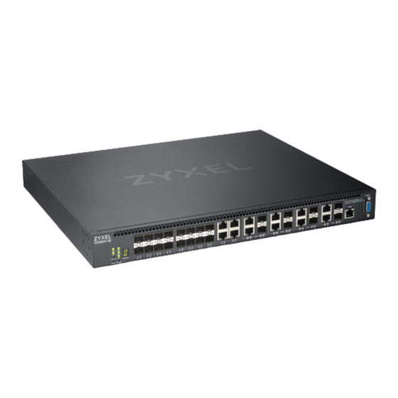
Ethernet ports support Multi-Gigabit (100 Mbps, 1 Gbps, 2.5 Gbps, 5 Gbps, and 10 Gbps). See Section 1.1.1 on page 23 for more information about Multi-Gigabit. The figure below shows the front panel of the Switch. Figure 10 Front Panel: XS3800-28 The following table describes the ports. Table 3 Panel Connections CONNECTOR DESCRIPTION 16 10 GbE SFP+ Slots Use SFP+ transceivers in these ports for high-bandwidth backbone connections. -
Page 36: Sfp/Sfp+ Slots
Use the following steps to install a transceiver. Insert the transceiver into the slot with the exposed section of PCB board facing down. Figure 11 Transceiver Installation Example Press the transceiver firmly until it clicks into place. XS3800-28 User’s Guide... -
Page 37: Ethernet Ports
When auto-negotiation is turned on, an Ethernet port negotiates with the peer automatically to determine the connection speed and duplex mode. If the peer Ethernet port does not support auto- negotiation or turns off this feature, the Switch determines the connection speed by detecting the signal XS3800-28 User’s Guide... -
Page 38: Dual Personality Interfaces
For local management, you can use a computer with terminal emulation software configured to the following parameters: • VT100 terminal emulation • 115200 bps • No parity, 8 data bits, 1 stop bit • No flow control XS3800-28 User’s Guide... -
Page 39: Rear Panel
The following figures show the rear panels of the Switch. The rear panels contain: • Two AC power receptacles (A and B) Figure 16 Rear Panel: XS3800-28 3.2.1 Grounding Grounding is a safety measure to have unused electricity return to the ground. It prevents damage to the Switch, and protects you from electrocution. -
Page 40: Ac Power Connection
The Switch detected a power supply failure with the power cable connected to the Switch and a power source. • The fans are not functioning at a proper speed or malfunctioning. The Switch is not receiving power from the power module in the first power slot. XS3800-28 User’s Guide... - Page 41 The port is receiving or transmitting data at 100 Mbps/1 Gbps/2.5 Gbps/5 Gbps. Blue The port has a successful 10 Gbps connection. Blinking The port is receiving or transmitting data at 10 Gbps. This link is disconnected or the port is disabled. SFP+ Slots XS3800-28 User’s Guide...
- Page 42 Mbps through the MGMT port. The MGMT port is not connected to an Ethernet device, or the port is disabled. STACK ID The LED is showing the Stack ID number of the Switch. ID 0 means it is a standalone Switch. XS3800-28 User’s Guide...
-
Page 43: The Web Configurator
Also, you can use the ZON Utility to check your Switch’s IP address. See Section 4.3 on page 46 for more information on the ZON utility. The following screen appears. XS3800-28 User’s Guide... - Page 44 If you didn’t change the default administrator password and/or SNMP community values, a warning screen displays each time you log into the web configurator. Click Password / SNMP to open a screen where you can change the administrator and SNMP passwords simultaneously. Otherwise, click Ignore to close it. XS3800-28 User’s Guide...
- Page 45 Get Community Enter the Get Community string, which is the password for the incoming Get- and GetNext- requests from the management station. The Get Community string is only used by SNMP managers using SNMP version 2c or lower. XS3800-28 User’s Guide...
-
Page 46: Zyxel One Network (Zon) Utility
Note: To check for your Windows operating system version, right-click on My Computer > Properties. You should see this information in the General tab. Hardware Here are the minimum hardware requirements to use the ZON Utility on your PC. • Core i3 processor • 2GB RAM XS3800-28 User’s Guide... -
Page 47: Run The Zon Utility
ZON icon in the upper right hand corner of the screen. Then select the Supported model and firmware version link. If your device is not listed here, see the device release notes for ZON utility support. The release notes are in the firmware zip file on the Zyxel web site. XS3800-28 User’s Guide... - Page 48 Select a device and then use the icons to perform actions. Some functions may not be available for your devices. Note: You must know the selected device admin password before taking actions on the device using the ZON utility icons. XS3800-28 User’s Guide...
- Page 49 Use this icon to save configuration changes to permanent memory on a selected device. 13 Settings Use this icon to select a network adaptor for the computer on which the ZON utility is installed, and the utility language. XS3800-28 User’s Guide...
-
Page 50: The Web Configurator Layout
This field displays the hardware version of the discovered device. 4.4 The Web Configurator Layout The Status screen is the first screen that displays when you access the web configurator. The following figure shows the navigating components of a web configurator screen. XS3800-28 User’s Guide... - Page 51 G - Click this link to go to the NCC (Nebula Control Center) portal website. H - Click this link to go to the Neighbor screen where you can see and manage neighbor devices learned by the Switch. XS3800-28 User’s Guide...
- Page 52 MAC address learning, GARP and priority queues. IP Setup This link takes you to a screen where you can configure the IP address, subnet mask (necessary for Switch management) and set up to 128 IP routing domains. XS3800-28 User’s Guide...
- Page 53 VLAN Stacking This link takes you to screens where you can activate and configure VLAN stacking. Multicast This link takes you to screen where you can configure various multicast features, IGMP snooping, MLD snooping-proxy and create multicast VLANs. XS3800-28 User’s Guide...
- Page 54 This link takes you to screens where you can configure redundant virtual router for your network. Router Setup This link takes you to a screen where you can enable Equal-Cost MultiPath (ECMP) routing and set the criteria the Switch uses to determine the routing path for a packet. XS3800-28 User’s Guide...
-
Page 55: Change Your Password
This link takes you to a screen where you can view the port statistics. 4.4.1 Change Your Password After you log in for the first time, it is recommended you change the default administrator password. Click Management > Access Control > Logins to display the next screen. XS3800-28 User’s Guide... -
Page 56: Saving Your Configuration
Delete all port-based VLANs with the CPU port as a member. The “CPU port” is the management port of the Switch. Filter all traffic to the CPU port. Disable all ports. Misconfigure the text configuration file. Forget the password and/or IP address. XS3800-28 User’s Guide... -
Page 57: Resetting The Switch
Type atlc after the “Enter Debug Mode” message. Wait for the “Starting XMODEM upload” message before activating XMODEM upload on your terminal. After a configuration file upload, type atgo to restart the Switch. XS3800-28 User’s Guide... -
Page 58: Logging Out Of The Web Configurator
Figure 30 Web Configurator: Logout Screen 4.9 Help The web configurator’s online help has descriptions of individual screens and some supplementary information. Click the Help link from a web configurator screen to view an online help description of that screen. XS3800-28 User’s Guide... -
Page 59: Initial Setup Example
In this example, you want to configure port 1 as a member of VLAN 2. Figure 31 Initial Setup Network Example: VLAN Click Advanced Application > VLAN > VLAN Configuration in the navigation panel and click the Static VLAN Setup link. XS3800-28 User’s Guide... -
Page 60: Setting Port Vid
Use PVID to add a tag to incoming untagged frames received on that port so that the frames are forwarded to the VLAN group that the tag defines. In the example network, configure 2 as the port VID on port 1 so that any untagged frames received on that port get sent to VLAN 2. XS3800-28 User’s Guide... -
Page 61: Configuring Switch Management Ip Address
Switch’s power is turned off. 5.1.3 Configuring Switch Management IP Address The default management IP address of the Switch is 192.168.1.1. You can configure another IP address in a different subnet for management purposes. The following figure shows an example. XS3800-28 User’s Guide... - Page 62 This is the same as the VLAN ID you configure in the Static VLAN screen. Click Add to save your changes back to the run-time memory. Settings in the run-time memory are lost when the Switch’s power is turned off. XS3800-28 User’s Guide...
-
Page 63: Tutorials
DHCP Server (A) 1 and 100 DHCP Client (B) 1 and 100 DHCP Client (C) 1 and 100 Access the Switch through http://192.168.1.1 by default. Log into the Switch by entering the username (default: admin) and password (default: 1234). XS3800-28 User’s Guide... - Page 64 Go to Advanced Application > VLAN > VLAN Configuration > VLAN Port Setup, and set the PVID of the ports 5, 6 and 7 to 100. This tags untagged incoming frames on ports 5, 6 and 7 with the tag 100. Figure 36 Tutorial: Tag Untagged Frames XS3800-28 User’s Guide...
- Page 65 The DHCP Snooping Port Configure screen appears. Select Trusted in the Server Trusted state field for port 5 because the DHCP server is connected to port 5. Keep ports 6 and 7 Untrusted because they are connected to DHCP clients. Click Apply. Figure 38 Tutorial: Set the DHCP Server Port to Trusted XS3800-28 User’s Guide...
-
Page 66: How To Use Dhcpv4 Relay On The Switch
6.3 How to Use DHCPv4 Relay on the Switch This tutorial describes how to configure your Switch to forward DHCP client requests to a specific DHCP server. The DHCP server can then assign a specific IP address based on the information in the DHCP requests. XS3800-28 User’s Guide... -
Page 67: Dhcp Relay Tutorial Introduction
Access the web configurator through the Switch’s management port. Go to Basic Setting > Switch Setup and set the VLAN type to 802.1Q. Click Apply to save the settings to the run-time memory. Figure 42 Tutorial: Set VLAN Type to 802.1Q XS3800-28 User’s Guide... - Page 68 Enter 102 in the PVID field for port 2 to add a tag to incoming untagged frames received on that port so that the frames are forwarded to the VLAN group that the tag defines. 10 Click Apply to save your changes back to the run-time memory. XS3800-28 User’s Guide...
-
Page 69: Configuring Dhcpv4 Relay
Figure 46 Tutorial: Set DHCP Server and Relay Information Click the Save link in the upper right corner of the web configurator to save your configuration permanently. The DHCP server can then assign a specific IP address based on the DHCP request. XS3800-28 User’s Guide... -
Page 70: Troubleshooting
Switch load this auto configuration file, two conditions listed above must be met. Please refer to the following steps to see how to set up a Vendor Class Identifier on the Switch. Setting up a TFTP Server Select a directory on the TFTP server. Put the configuration files in that directory. XS3800-28 User’s Guide... - Page 71 In the Basic Setting > IP Setup > IP Configuration screen, select the check box in the Option-60 field, and enter a Vendor Class Identifier in the Class-ID field. In this example, we use “ZyxelCorp”. Click Apply to save your changes. See Section 8.4 on page 89 for more information. XS3800-28 User’s Guide...
- Page 72 For example, if you save the auto configuration setting to Config 1, you need to click the Config 1 button next to the Reboot System field. See Section 51.4 on page 482 for more information. XS3800-28 User’s Guide...
- Page 73 Check the screens to see if it’s the configuration file you want to load. If it’s not, go through the steps above to check your configurations. If it is, click Save at the top right corner of the web configurator to save the configuration permanently. Figure 52 Tutorial: Save XS3800-28 User’s Guide...
-
Page 74: Technical Reference
Technical Reference... -
Page 75: Status
The Status screen displays when you log into the Switch or click Status at the top right corner of the web configurator. The Status screen displays general device information, system status, and its IP addresses. Figure 53 Status XS3800-28 User’s Guide... - Page 76 This field displays the hardware version number of the Switch. The integer is the model version, and the decimal is the version of the hardware change. For example, V1.0 is a hardware version for the Switch where 1 identifies the XS3800-28, and .0 is the first hardware change.
-
Page 77: Neighbor Screen
This shows the port description of the Switch. PoE Draw This shows the power consumption that the neighboring device connected to this port draws from the Switch. This allows you to plan and use within the power budget of the Switch. Remote XS3800-28 User’s Guide... - Page 78 Note: The Switch must support power sourcing (PSE) or the network device is a powered device (PD). Note: If multiple neighbor devices use the same port, the Reset button is not available and will show “-” instead. Note: You can only reset Zyxel powered devices that support the ZON utility XS3800-28 User’s Guide...
-
Page 79: Basic Setting
8.1 System Information In the navigation panel, click Basic Setting > System Info to display the screen as shown. You can check the firmware version number and monitor the Switch temperature, fan speeds and voltage in this screen. XS3800-28 User’s Guide... - Page 80 Chapter 8 Basic Setting Figure 55 Basic Setting > System Info (Standalone Mode) XS3800-28 User’s Guide...
- Page 81 BOARD, MAC and PHY refer to the location of the temperature sensors on the Switch printed circuit board. Current This shows the current temperature at this sensor. This field displays the maximum temperature measured at this sensor. This field displays the minimum temperature measured at this sensor. XS3800-28 User’s Guide...
-
Page 82: System Information Stacking Hardware Monitor
This shows if the Switch is properly operating from the connected power source. 8.1.1 System Information Stacking Hardware Monitor Click a slot number in the System Information screen to display more detailed hardware information on a Switch. XS3800-28 User’s Guide... - Page 83 This field displays this fan's maximum speed measured in RPM. This field displays this fan's minimum speed measured in RPM. “<41" is displayed for speeds too small to measure (under 2000 RPM). Threshold This field displays the minimum speed at which a normal fan should work. XS3800-28 User’s Guide...
-
Page 84: General Setup
Use this screen to configure general settings such as the system name and time. Click Basic Setting > General Setup in the navigation panel to display the screen as shown. Figure 58 Basic Setting > General Setup XS3800-28 User’s Guide... - Page 85 GMT or UTC). So in the European Union you would select Last, Sunday, March and the last field depends on your time zone. In Germany for instance, you would select 2:00 because Germany's time zone is one hour ahead of GMT or UTC (GMT+1). XS3800-28 User’s Guide...
-
Page 86: Switch Setup
Click Basic Setting > Switch Setup in the navigation panel to display the screen as shown. The VLAN setup screens change depending on whether you choose 802.1Q or Port Based in the VLAN Type field in this screen (in Standalone mode). Refer to the chapter on VLAN. XS3800-28 User’s Guide... - Page 87 Basic Setting > Stacking > Configuration), so this field does not display in stacking mode. Bridge Control Select Active to allow the Switch to handle bridging control protocols (STP, for example). You Protocol also need to define how to treat a BPDU in the Port Setup screen. Transparency XS3800-28 User’s Guide...
- Page 88 Save link on the top navigation panel to save your changes to the non-volatile memory when you are done configuring. Cancel Click Cancel to begin configuring this screen afresh. XS3800-28 User’s Guide...
-
Page 89: Ip Setup
This field displays the VLAN identification number of the IP domain on the Switch. Type This shows whether this IP address is dynamically assigned from a DHCP server or manually assigned (Static). Renew Click this to renew the dynamic IP address. Release Click this to release the dynamic IP address. XS3800-28 User’s Guide... -
Page 90: Ip Status Details
This displays the length of time in seconds that this interface can use the current dynamic IP address from the DHCP server. Renew Time This displays the length of time from the lease start that the Switch will request to renew its current dynamic IP address from the DHCP server. XS3800-28 User’s Guide... -
Page 91: Ip Configuration
This displays the IP address of the primary and secondary DNS servers assigned by the DHCP server. 0.0.0.0 means no DNS server is assigned. 8.4.3 IP Configuration Use this screen to configure the default gateway device, the default domain name server and add IP domains. XS3800-28 User’s Guide... - Page 92 MGMT. This means that device(s) connected to the other port(s) do not receive these packets. Select In-Band to have the Switch send the packets to all ports except the management port (labelled MGMT) to which connected device(s) do not receive these packets. XS3800-28 User’s Guide...
- Page 93 This field displays the subnet mask of the Switch in the IP domain. This field displays the VLAN identification number of the IP domain on the Switch. Type This field displays the type of IP address status. XS3800-28 User’s Guide...
-
Page 94: Port Setup
Click Cancel to clear the check boxes. 8.5 Port Setup Use this screen to configure Switch port settings. Click Basic Setting > Port Setup in the navigation panel to display the configuration screen. Figure 65 Basic Setting > Port Setup (Standalone mode) XS3800-28 User’s Guide... - Page 95 Note: Changes in this row are copied to all the ports as soon as you make them. Active Select this check box to enable a port. The factory default for all ports is enabled. A port must be enabled for data transmission to occur. XS3800-28 User’s Guide...
- Page 96 Save link on the top navigation panel to save your changes to the non-volatile memory when you are done configuring. Cancel Click Cancel to begin configuring this screen afresh. XS3800-28 User’s Guide...
-
Page 97: Interface Setup
Select an entry’s check box to select a specific entry. Otherwise, select the check box in the table heading row to select all entries. Delete Click Delete to remove the selected entry from the summary table. Cancel Click Cancel to clear the check boxes. XS3800-28 User’s Guide... -
Page 98: Ipv6
This field displays whether the IPv6 interface is activated or not. 8.7.1 IPv6 Interface Status Use this screen to view a specific IPv6 interface status and detailed information. Click an interface index number in the Basic Setting > IPv6 screen. The following screen opens. XS3800-28 User’s Guide... - Page 99 ND DAD Active This field displays whether Neighbor Discovery (ND) Duplicate Address Detection (DAD) is enabled on the interface. Number of DAD This field displays the number of consecutive neighbor solicitations the Switch sends for this Attempts interface. XS3800-28 User’s Guide...
-
Page 100: Ipv6 Configuration
Client address and DNS information for this interface. 8.7.2 IPv6 Configuration Use this screen to configure IPv6 settings on the Switch. Click the IPv6 Configuration link in the Basic Setting > IPv6 screen. The following screen opens. XS3800-28 User’s Guide... -
Page 101: Ipv6 Global Setup
Use this screen to configure the global IPv6 settings. Click the link next to IPv6 Global Setup in the IPv6 Configuration screen to display the screen as shown next. Figure 71 Basic Setting > IPv6 > IPv6 Configuration > IPv6 Global Setup XS3800-28 User’s Guide... -
Page 102: Ipv6 Interface Setup
This is the interface index number. Click on an index number to change the settings. Interface This is the name of the IPv6 interface you created. Active This field displays whether the IPv6 interface is activated or not. XS3800-28 User’s Guide... -
Page 103: Ipv6 Link-Local Address Setup
This is the default gateway IPv6 address for the interface. 8.7.6 IPv6 Global Address Setup Use this screen to configure the interface’s IPv6 global address. Click the link next to IPv6 Global Address Setup in the IPv6 Configuration screen to display the screen as shown next. XS3800-28 User’s Guide... -
Page 104: Ipv6 Neighbor Discovery Setup
8.7.7 IPv6 Neighbor Discovery Setup Use this screen to configure neighbor discovery settings for each interface. Click the link next to IPv6 Neighbor Discovery Setup in the IPv6 Configuration screen to display the screen as shown next. XS3800-28 User’s Guide... -
Page 105: Ipv6 Router Discovery Setup
8.7.8 IPv6 Router Discovery Setup Use this screen to configure router discovery settings for each interface. Click the link next to IPv6 Router Discovery Setup in the IPv6 Configuration screen to display the screen as shown next. XS3800-28 User’s Guide... - Page 106 This is the interface index number. Click on an index number to change the settings. Interface This is the name of the IPv6 interface you created. Flags This field displays whether IPv6 hosts use DHCPv6 to obtain IPv6 stateful addresses (M) and/ or additional configuration settings (O). XS3800-28 User’s Guide...
-
Page 107: Ipv6 Prefix Setup
Specify how long (from 0 to 4294967295 seconds) the prefix is valid for on-link determination. Preferred Lifetime Specify how long (from 0 to 4294967295 seconds) that addresses generated from the prefix via stateless address autoconfiguration remain preferred. The preferred lifetime cannot exceed the valid lifetime. XS3800-28 User’s Guide... -
Page 108: Ipv6 Neighbor Setup
Use this screen to create a static IPv6 neighbor entry in the Switch’s IPv6 neighbor table to store the neighbor information permanently. Click the link next to IPv6 Neighbor Setup in the IPv6 Configuration screen to display the screen as shown next. Figure 78 Basic Setting > IPv6 > IPv6 Configuration > IPv6 Neighbor Setup XS3800-28 User’s Guide... -
Page 109: Dhcpv6 Client Setup
Use this screen to configure the Switch’s DHCP settings when it is acting as a DHCPv6 client. Click the link next to IPv6 Neighbor Setup in the IPv6 Configuration screen to display the screen as shown next. XS3800-28 User’s Guide... - Page 110 This field displays whether the Switch obtains a list of domain names from the DHCP server. Information Refresh This field displays the time interval (in seconds) at which the Switch exchanges other Minimum configuration information with a DHCPv6 server again. XS3800-28 User’s Guide...
-
Page 111: Stacking
Use the master Switch to assign a ‘slot ID’ for each ‘linecard’ non-master Switch. ‘Slot’ refers to a Switch in the ‘virtual chassis’ stack. The advantages of stacking are: • High port density - for example, two 24-port Switches can become one 48-port logical Switch XS3800-28 User’s Guide... -
Page 112: Stacking Status
This field displays the Ethernet speed of stacking channel 1 of the Switch. Stacking Channel2 Neighbor This field displays the neighbor Switch that is connected to slot channel 2 of the Switch. Speed This field displays the Ethernet speed of stacking channel 2 of the Switch. XS3800-28 User’s Guide... -
Page 113: Stacking Slot
This field displays the status of the port stacking channel 1 of the Switch. It will display up for Channel 1 active or down for inactive. Stacking This field displays the status of the port stacking channel 2 of the Switch. It will display up for Channel 2 active or down for inactive. XS3800-28 User’s Guide... -
Page 114: Stacking Configuration
- a Switch in the stack reboots (as happens after you change stacking mode to standalone) - you add a Switch to the stack or - a Switch in the stack shuts down. Use the following procedure to create a stack: XS3800-28 User’s Guide... - Page 115 See Section 8.5 on page 94 Section 9.7 on page 117 for details on the port settings. Click Basic Setting > Stacking > Configuration to see the following screen. Figure 84 Basic Setting > Stacking > Configuration XS3800-28 User’s Guide...
-
Page 116: Dns
Figure 85 Basic Setting > DNS The following table describes the labels in this screen. Table 39 Basic Setting > DNS LABEL DESCRIPTION Static Domain Name Server Preference This is the priority of the DNS server address. XS3800-28 User’s Guide... -
Page 117: Cloud Management
Figure 86 Basic Setting > Cloud Management 8.10.1 Nebula Center Control Discovery Click Basic Setting > Cloud Management > Nebula Control Center Discovery to display this screen. Figure 87 Basic Setting > Cloud Management > Nebula Control Center Discovery XS3800-28 User’s Guide... -
Page 118: Nebula Switch Registration
This screen has a QR code containing the Switch’s serial number and MAC address for handy NCC registration of the Switch using the Nebula Mobile app. First, download the app from the Google Play store for Android devices or the App Store for iOS devices and create an organization and site. XS3800-28 User’s Guide... -
Page 119: Vlan
A broadcast frame (or a multicast frame for a multicast group that is known by the system) is duplicated only on ports that are members of the VID (except the ingress port itself), thus confining the broadcast to a specific domain. XS3800-28 User’s Guide... -
Page 120: Automatic Vlan Registration
You may choose to accept both tagged and untagged Type incoming frames, just tagged incoming frames or just untagged incoming frames on a port. Ingress filtering If set, the Switch discards incoming frames for VLANs that do not have this port as a member. XS3800-28 User’s Guide... -
Page 121: Port Vlan Trunking
• sent to a group whether it has a VLAN tag or not. • blocked from a VLAN group regardless of its VLAN tag. You can also tag all outgoing frames (that were previously untagged) from a port with the specified VID. XS3800-28 User’s Guide... -
Page 122: Vlan Status
RMirror - manually added as a remote port mirroring VLAN • MVR - added via Multicast VLAN Registration (MVR) Change Pages Click Previous or Next to show the previous/next screen if all status information cannot be seen in one screen. XS3800-28 User’s Guide... -
Page 123: Vlan Details
U and ports not participating in a VLAN are marked as “–“. Elapsed Time This field shows how long it has been since a normal VLAN was registered or a static VLAN was set up. XS3800-28 User’s Guide... -
Page 124: Private Vlan Status
This shows the ports mapped to the private VLAN using the Advanced Application > Private VLAN or Advanced Application > VLAN > Static VLAN screen. Change Pages Use the Previous and Next buttons to display different pages. XS3800-28 User’s Guide... -
Page 125: Vlan Configuration
Click Click Here to configure the MAC Based VLAN for the Switch. 9.7.1 Configure a Static VLAN Use this screen to configure a static VLAN for the Switch. Click the Static VLAN Setup link in the VLAN Configuration screen to display the screen as shown next. XS3800-28 User’s Guide... - Page 126 Chapter 9 VLAN Figure 96 Advanced Application > VLAN > VLAN Configuration > Static VLAN Setup (Standalone Mode) XS3800-28 User’s Guide...
- Page 127 51-53 includes 51, 52 and 53, but 51,53 does not include 52. Secondary private VLANs can only be associated with one primary private VLAN. SLOT This field appears only in stacking mode. Click the drop-down list to choose the slot number of the Switch in a stack. XS3800-28 User’s Guide...
-
Page 128: Configure Vlan Port Settings
Use the VLAN Port Setting screen to configure the static VLAN (IEEE 802.1Q) settings on a port. See Section 9.1 on page 119 for more information on 802.1Q VLAN. Click the VLAN Port Setup link in the VLAN Configuration screen. XS3800-28 User’s Guide... - Page 129 Chapter 9 VLAN Figure 98 Advanced Application > VLAN > VLAN Configuration > VLAN Port Setup (Standalone Mode) Figure 99 Advanced Application > VLAN > VLAN Configuration > VLAN Port Setup (Stacking Mode) XS3800-28 User’s Guide...
-
Page 130: Subnet Based Vlans
When a frame is received on a port, the Switch checks if a tag is added already and the IP subnet it came from. The untagged packets from the same IP subnet are then placed in the same XS3800-28 User’s Guide... - Page 131 Figure 100 Subnet Based VLAN Application Example 9.7.3.1 Configuring Subnet Based VLAN Click the Subnet Based VLAN Setup link in the VLAN Configuration screen to display the configuration screen as shown. XS3800-28 User’s Guide...
- Page 132 Index This is the index number identifying this subnet based VLAN. Click on any of these numbers to edit an existing subnet based VLAN. Active This field shows whether the subnet based VLAN is active or not. XS3800-28 User’s Guide...
-
Page 133: Protocol Based Vlans
C. Figure 102 Protocol Based VLAN Application Example 9.7.4.1 Configuring Protocol Based VLAN Click the Protocol Based VLAN Setup link in the VLAN Configuration screen to display the configuration screen as shown. XS3800-28 User’s Guide... - Page 134 This port must belong to a static VLAN in order to participate in a protocol based VLAN. See Chapter 9 on page 119 for more details on setting up VLANs. Name Enter up to 32 alphanumeric characters to identify this protocol based VLAN. XS3800-28 User’s Guide...
- Page 135 Select the protocol. Leave the default value IP. Type the VLAN ID of an existing VLAN. In our example we already created a static VLAN with an ID of 5. Type 5. Leave the priority set to 0 and click Add. XS3800-28 User’s Guide...
-
Page 136: Voice Vlan
You can set priority level to the Voice VLAN and add MAC address of IP phones from specific manufacturers by using its ID from the Organizationally Unique Identifiers (OUI). Click the Voice VLAN Setup link in the VLAN Configuration screen to display the configuration screen as shown. XS3800-28 User’s Guide... - Page 137 For example, if you set the MAC address to 00:13:49:00:00:00 and the mask to ff:ff:ff:00:00:00, a packet with a MAC address of 00:13:49:12:34:56 matches this criteria. Description Type an description up to 32 characters for the Voice VLAN device. For example: Siemens. XS3800-28 User’s Guide...
-
Page 138: Mac Based Vlan
MAC address in the MAC-based VLAN setup screen. You can also delete a MAC-based VLAN entry in the same screen. Click the MAC-based VLAN Setup link in the VLAN Configuration screen to see the following screen. Figure 107 Advanced Application > VLAN > VLAN Configuration > MAC-based VLAN Setup XS3800-28 User’s Guide... -
Page 139: Port-Based Vlan Setup
Select Port Based as the VLAN Type in the Switch Setup screen and then click VLAN from the navigation panel to display the following screen. Select either All Connected or Port Isolated from the drop-down list depending on your VLAN and VLAN security requirements. If VLAN members need to communicate XS3800-28 User’s Guide... - Page 140 Click Apply to save your settings. The following screen shows users on a port-based, all-connected VLAN configuration. Figure 108 Advanced Application > VLAN > Port Based VLAN Setup (All Connected) The following screen shows users on a port-based, port-isolated VLAN configuration. XS3800-28 User’s Guide...
- Page 141 (its outgoing port). CPU refers to the Switch management port. By default it forms a VLAN with all Ethernet ports. If it does not form a VLAN with a particular port then the Switch cannot be managed from that port. XS3800-28 User’s Guide...
- Page 142 Save link on the top navigation panel to save your changes to the non-volatile memory when you are done configuring. Cancel Click Cancel to begin configuring this screen afresh. XS3800-28 User’s Guide...
-
Page 143: Static Mac Forward Setup
Chapter 20 on page 225 for more information on port security. Click Advanced Application > Static MAC Forwarding in the navigation panel to display the configuration screen as shown. Figure 110 Advanced Application > Static MAC Forwarding (Standalone Mode) XS3800-28 User’s Guide... - Page 144 In stacking mode, the first number represents the slot ID and the second is the port number. Select an entry’s check box to select a specific entry. Otherwise, select the check box in the table heading row to select all entries. XS3800-28 User’s Guide...
- Page 145 Chapter 10 Static MAC Forward Setup Table 52 Advanced Application > Static MAC Forwarding (continued) LABEL DESCRIPTION Delete Click Delete to remove the selected entry from the summary table. Cancel Click Cancel to clear the check boxes. XS3800-28 User’s Guide...
-
Page 146: Static Multicast Forward Setup
With static multicast forwarding, you can forward these multicasts to port(s) within a VLAN group. Figure 113 shows frames being forwarded to devices connected to port 3. Figure 114 shows frames being forwarded to ports 2 and 3 within VLAN group 4. Figure 112 No Static Multicast Forwarding XS3800-28 User’s Guide... -
Page 147: Configuring Static Multicast Forwarding
11.2 Configuring Static Multicast Forwarding Use this screen to configure rules to forward specific multicast frames, such as streaming or control frames, to specific port(s). Click Advanced Application > Static Multicast Forwarding to display the configuration screen as shown. XS3800-28 User’s Guide... - Page 148 MAC Address This field displays the multicast MAC address that identifies a multicast group. This field displays the ID number of a VLAN group to which frames containing the specified multicast MAC address will be forwarded. XS3800-28 User’s Guide...
- Page 149 Select an entry’s check box to select a specific entry. Otherwise, select the check box in the table heading row to select all entries. Delete Click Delete to remove the selected entry from the summary table. Cancel Click Cancel to clear the check boxes. XS3800-28 User’s Guide...
-
Page 150: Filtering
Select Discard destination to drop frames to the destination MAC address (specified in the MAC address). The Switch can still receive frames originating from the MAC address. Select Discard source and Discard destination to block traffic to/from the MAC address specified in the MAC field. XS3800-28 User’s Guide... - Page 151 Select an entry’s check box to select a specific entry. Otherwise, select the check box in the table heading row to select all entries. Delete Check the rule(s) that you want to remove and then click the Delete button. Cancel Click Cancel to clear the selected checkbox(es). XS3800-28 User’s Guide...
-
Page 152: Spanning Tree Protocol
In RSTP, the port states are Discarding, Learning, and Forwarding. Note: In this user’s guide, “STP” refers to both STP and RSTP. STP Terminology The root bridge is the base of the spanning tree. XS3800-28 User’s Guide... - Page 153 Note: The listening state does not exist in RSTP. Learning All BPDUs are received and processed. Information frames are submitted to the learning process but not forwarded. Forwarding All BPDUs are received and processed. All information frames are received and forwarded. XS3800-28 User’s Guide...
-
Page 154: Spanning Tree Protocol Status Screen
VLANs to use the same spanning tree. • Load-balancing is possible as traffic from different VLANs can use distinct paths in a region. 13.2 Spanning Tree Protocol Status Screen Click Advanced Application > Spanning Tree Protocol to see the screen as shown. XS3800-28 User’s Guide... -
Page 155: Spanning Tree Configuration
Save link on the top navigation panel to save your changes to the non-volatile memory when you are done configuring. Cancel Click Cancel to begin configuring this screen afresh. XS3800-28 User’s Guide... -
Page 156: Configure Rapid Spanning Tree Protocol
Use this screen to configure RSTP settings, see Section 13.10 on page 175 for more information on RSTP. Click RSTP in the Advanced Application > Spanning Tree Protocol screen. Figure 120 Advanced Application > Spanning Tree Protocol > RSTP (Standalone Mode) XS3800-28 User’s Guide... - Page 157 LAN. If it is a root port, a new root port is selected from among the switch ports attached to the network. The allowed range is 6 to 40 seconds. XS3800-28 User’s Guide...
-
Page 158: Rapid Spanning Tree Protocol Status
Click Cancel to begin configuring this screen afresh. 13.5 Rapid Spanning Tree Protocol Status Click Advanced Application > Spanning Tree Protocol in the navigation panel to display the status screen as shown next. See Section 13.10 on page 175 for more information on RSTP. XS3800-28 User’s Guide... - Page 159 This is the time (in seconds) the root switch will wait before changing states (that is, listening to (second) learning to forwarding). See Section on page 153 for information on port states. Note: The listening state does not exist in RSTP. XS3800-28 User’s Guide...
-
Page 160: Configure Multiple Rapid Spanning Tree Protocol
Forwarding - the Switch unblocks and allows the port to forward frames again. 13.6 Configure Multiple Rapid Spanning Tree Protocol To configure MRSTP, click MRSTP in the Advanced Application > Spanning Tree Protocol screen. See Section 13.10 on page 175 for more information on MRSTP. XS3800-28 User’s Guide... - Page 161 Chapter 13 Spanning Tree Protocol Figure 124 Advanced Application > Spanning Tree Protocol > MRSTP (Standalone Mode) Figure 125 Advanced Application > Spanning Tree Protocol > MRSTP (Stacking Mode) XS3800-28 User’s Guide...
- Page 162 Note: An edge port becomes a non-edge port as soon as it receives a Bridge Protocol Data Unit (BPDU). XS3800-28 User’s Guide...
-
Page 163: Multiple Rapid Spanning Tree Protocol Status
See Section 13.10 on page 175 for more information on MRSTP. Note: This screen is only available after you activate MRSTP on the Switch. Figure 126 Advanced Application > Spanning Tree Protocol > Status: MRSTP (Standalone Mode) XS3800-28 User’s Guide... - Page 164 This field appears only in stacking mode. Click the drop-down list to choose the slot number of the Switch in a stack. Port This field displays the number of the port on the Switch. In stacking mode, the first number represents the slot ID and the second is the port number. XS3800-28 User’s Guide...
-
Page 165: Configure Multiple Spanning Tree Protocol
Forwarding - the Switch unblocks and allows the port to forward frames again. 13.8 Configure Multiple Spanning Tree Protocol To configure MSTP, click MSTP in the Advanced Application > Spanning Tree Protocol screen. See Section on page 154 for more information on MSTP. XS3800-28 User’s Guide... - Page 166 Chapter 13 Spanning Tree Protocol Figure 128 Advanced Application > Spanning Tree Protocol > MSTP (Standalone Mode) XS3800-28 User’s Guide...
- Page 167 Chapter 13 Spanning Tree Protocol Figure 129 Advanced Application > Spanning Tree Protocol > MSTP (Stacking Mode) XS3800-28 User’s Guide...
- Page 168 Clear - to remove all VLAN(s) from being mapped to this MST instance. Enabled VLAN(s) This field displays which VLAN(s) are mapped to this MST instance. SLOT This field appears only in stacking mode. Click the drop-down list to choose the slot number of the Switch in a stack. XS3800-28 User’s Guide...
-
Page 169: Multiple Spanning Tree Protocol Port Configuration
Check the rule(s) that you want to remove and then click the Delete button. Cancel Click Cancel to clear the selected checkbox(es). 13.8.1 Multiple Spanning Tree Protocol Port Configuration To configure MSTP ports, click Port in the Advanced Application > Spanning Tree Protocol > MSTP screen. XS3800-28 User’s Guide... - Page 170 Chapter 13 Spanning Tree Protocol Figure 130 Advanced Application > Spanning Tree Protocol > MSTP > Port (Standalone Mode) Figure 131 Advanced Application > Spanning Tree Protocol > MSTP > Port (Stacking Mode) XS3800-28 User’s Guide...
-
Page 171: Multiple Spanning Tree Protocol Status
Click Advanced Application > Spanning Tree Protocol in the navigation panel to display the status screen as shown next. See Section on page 154 for more information on MSTP. Note: This screen is only available after you activate MSTP on the Switch. XS3800-28 User’s Guide... - Page 172 Chapter 13 Spanning Tree Protocol Figure 132 Advanced Application > Spanning Tree Protocol > Status: MSTP (Standalone Mode) XS3800-28 User’s Guide...
- Page 173 This is the path cost from the root port on this Switch to the root switch. Port ID This is the priority and number of the port on the Switch through which this Switch must communicate with the root of the Spanning Tree. XS3800-28 User’s Guide...
- Page 174 This field displays the identifier of the designated bridge to which this port belongs when the port is a designated port. Otherwise, it displays the identifier of the designated bridge for the LAN segment to which this port is connected. XS3800-28 User’s Guide...
-
Page 175: Technical Reference
Figure 134 STP/RSTP Network Example With MSTP, VLANs 1 and 2 are mapped to different spanning trees in the network. Thus traffic from the two VLANs travel on different paths. The following figure shows the network example using MSTP. XS3800-28 User’s Guide... -
Page 176: Mst Region
Each created MSTI is identified by a unique number (known as an MST ID) known internally to a region. Thus an MSTI does not span across MST regions. The following figure shows an example where there are two MST regions. Regions 1 and 2 have 2 spanning tree instances. XS3800-28 User’s Guide... -
Page 177: Common And Internal Spanning Tree (Cist)
CIST. In an MSTP-enabled network, there is only one CIST that runs between MST regions and single spanning tree devices. A network may contain multiple MST regions and other network segments running RSTP. Figure 137 MSTP and Legacy RSTP Network Example XS3800-28 User’s Guide... -
Page 178: Bandwidth Control
Note: The sum of CIRs cannot be greater than or equal to the uplink bandwidth. 14.2 Bandwidth Control Setup Click Advanced Application > Bandwidth Control in the navigation panel to bring up the screen as shown next. XS3800-28 User’s Guide... - Page 179 LABEL DESCRIPTION Active Select this check box to enable bandwidth control on the Switch. SLOT This field appears only in stacking mode. Click the drop-down list to choose the slot number of the Switch in a stack. XS3800-28 User’s Guide...
- Page 180 Save link on the top navigation panel to save your changes to the non-volatile memory when you are done configuring. Cancel Click Cancel to begin configuring this screen afresh. XS3800-28 User’s Guide...
-
Page 181: Broadcast Storm Control
Click Advanced Application > Broadcast Storm Control in the navigation panel to display the screen as shown next. Figure 140 Advanced Application > Broadcast Storm Control (Standalone Mode) XS3800-28 User’s Guide... - Page 182 The Switch will generate a trap and/or log when the actual rate is higher than the specified threshold. DLF (pkt/s) Select this option to enable and specify how many destination lookup failure (DLF) packets the Switch accepts per second on the port. XS3800-28 User’s Guide...
- Page 183 Save link on the top navigation panel to save your changes to the non-volatile memory when you are done configuring. Cancel Click Cancel to begin configuring this screen afresh. XS3800-28 User’s Guide...
-
Page 184: Mirroring
VLAN tagging and copied to the connected port(s). Traffic are then carried over the specified remote port mirroring (RMirror) VLAN and sent to the destination device’s monitor port through the connected ports that connect to other switches. XS3800-28 User’s Guide... - Page 185 Switch adds RMirror VLAN tag and forwards mirrored traffic from the mirroring port to the connected port directly. Multi-Destination RMirror If you configure more than one connected port on the source switch to forward the mirrored traffic to multiple destination switches, you must enable a reflector port on the source switch. XS3800-28 User’s Guide...
-
Page 186: Local Port Mirroring
16.1.1 Local Port Mirroring Click Advanced Application > Mirroring in the navigation panel to display the Mirroring screen. Use this screen to select a monitor port and specify the traffic flow to be copied to the monitor port. XS3800-28 User’s Guide... - Page 187 Chapter 16 Mirroring Figure 142 Advanced Application > Mirroring (Standalone Mode) Figure 143 Advanced Application > Mirroring (Stacking Mode) XS3800-28 User’s Guide...
-
Page 188: Remote Port Mirroring
Note: Your Switch automatically creates a static VLAN (with the same VID) when you create a RMirror VLAN in this screen. Click the RMirror link in the Advanced Application > Mirroring screen. The following screen opens. Figure 144 Advanced Application > Mirroring > RMirror XS3800-28 User’s Guide... -
Page 189: Source
Use this screen to configure the reflector port and specify the traffic flow to be copied to the monitor port when the Switch is the source device in remote port mirroring. Click the Source link in the RMirror screen. The following screen opens. XS3800-28 User’s Guide... - Page 190 Chapter 16 Mirroring Figure 145 Advanced Application > Mirroring > RMirror > Source (Standalone Mode) XS3800-28 User’s Guide...
- Page 191 Note: Changes in this row are copied to all the ports as soon as you make them. Mirrored Select this option to mirror the traffic on a port. XS3800-28 User’s Guide...
-
Page 192: Destination
Use this screen to specify the RMirror VLAN and configure the monitor port when the Switch is the destination device in remote port mirroring. Click the Destination link in the RMirror screen. The following screen opens. Figure 147 Advanced Application > Mirroring > RMirror > Destination (Standalone Mode) XS3800-28 User’s Guide... -
Page 193: Connected Port
Use this screen to select the RMirror VLAN and specify the port(s) that helps forward mirrored traffic to other connected switches and/or receive mirrored traffic from other connected port in the same RMirror VLAN. Click the Connected Port link in the RMirror screen. The following screen opens. XS3800-28 User’s Guide... - Page 194 Chapter 16 Mirroring Figure 149 Advanced Application > Mirroring > RMirror > Connected Port (Standalone Mode) Figure 150 Advanced Application > Mirroring > RMirror > Connected Port (Stacking Mode) XS3800-28 User’s Guide...
- Page 195 Click Cancel to begin configuring this screen afresh. VLAN This field displays the ID number of port mirroring VLAN over which the mirrored traffic is forwarded. Connected Port This field displays the number of port(s) that helps forward mirrored traffic to other connected switches. XS3800-28 User’s Guide...
-
Page 196: Link Aggregation
• You must connect all ports point-to-point to the same Ethernet switch and configure the ports for LACP trunking. • LACP only works on full-duplex links. • All ports in the same trunk group must have the same media type, speed, duplex mode and flow control settings. XS3800-28 User’s Guide... -
Page 197: Link Aggregation Id
17.3 Link Aggregation Status Click Advanced Application > Link Aggregation in the navigation panel. The Link Aggregation Status screen displays by default. See Section 17.1 on page 196 for more information. Figure 151 Advanced Application > Link Aggregation Status XS3800-28 User’s Guide... -
Page 198: Link Aggregation Setting
LACP - if the ports are configured to join a trunk group via LACP. 17.4 Link Aggregation Setting Click Advanced Application > Link Aggregation > Link Aggregation Setting to display the screen shown next. See Section 17.1 on page 196 for more information on link aggregation. XS3800-28 User’s Guide... - Page 199 Chapter 17 Link Aggregation Figure 152 Advanced Application > Link Aggregation > Link Aggregation Setting (Standalone Mode) XS3800-28 User’s Guide...
- Page 200 This is the only screen you need to configure to enable static link aggregation. Aggregation Setting Group ID The field identifies the link aggregation group, that is, one logical link containing multiple ports. Active Select this option to activate a trunk group. XS3800-28 User’s Guide...
-
Page 201: Link Aggregation Control Protocol
17.5 Link Aggregation Control Protocol Click in the Advanced Application > Link Aggregation > Link Aggregation Setting > LACP to display the screen shown next. See Section 17.2 on page 196 for more information on dynamic link aggregation. XS3800-28 User’s Guide... - Page 202 Chapter 17 Link Aggregation Figure 154 Advanced Application > Link Aggregation > Link Aggregation Setting > LACP (Standalone Mode) XS3800-28 User’s Guide...
- Page 203 (and lowest port number if system priority is the same) becomes the LACP “server”. The LACP “server” controls the operation of LACP setup. Enter a number to set the priority of an active port using Link Aggregation Control Protocol (LACP). The smaller the number, the higher the priority level. XS3800-28 User’s Guide...
-
Page 204: Static Trunking Example
T1, select the traffic distribution algorithm used by this group and select the ports that should belong to this group as shown in the figure below. Click Apply when you are done. XS3800-28 User’s Guide... - Page 205 Chapter 17 Link Aggregation Figure 157 Trunking Example - Configuration Screen EXAMPLE Your trunk group 1 (T1) configuration is now complete. XS3800-28 User’s Guide...
-
Page 206: Port Authentication
When the client provides the login credentials, the Switch sends an authentication request to a RADIUS server. The RADIUS server validates whether this client is allowed access to the port. XS3800-28 User’s Guide... -
Page 207: Mac Authentication
Switch does not prompt the client for login credentials. The login credentials are based on the source MAC address of the client connecting to a port on the Switch along with a password configured specifically for MAC authentication on the Switch. XS3800-28 User’s Guide... -
Page 208: Port Authentication Configuration
Select a port authentication method in the screen that appears. Figure 160 Advanced Application > Port Authentication 18.2.1 Activate IEEE 802.1x Security Use this screen to activate IEEE 802.1x security. In the Port Authentication screen click 802.1x to display the configuration screen as shown. XS3800-28 User’s Guide... - Page 209 Chapter 18 Port Authentication Figure 161 Advanced Application > Port Authentication > 802.1x (Standalone Mode) XS3800-28 User’s Guide...
- Page 210 Note: Changes in this row are copied to all the ports as soon as you make them. Active Select this checkbox to permit 802.1x authentication on this port. You must first allow 802.1x authentication on the Switch before configuring it on each port. XS3800-28 User’s Guide...
-
Page 211: Guest Vlan
VLAN. That is, unauthenticated users can have access to limited network resources in the same guest VLAN, such as the Internet. The rights granted to the Guest VLAN depends on how the network administrator configures switches or routers with the guest network feature. Figure 163 Guest VLAN Example XS3800-28 User’s Guide... - Page 212 Guest Vlan to display the configuration screen as shown. Figure 164 Advanced Application > Port Authentication > 802.1x > Guest VLAN (Standalone Mode) Figure 165 Advanced Application > Port Authentication > 802.1x > Guest VLAN (Stacking Mode) XS3800-28 User’s Guide...
-
Page 213: Activate Mac Authentication
Cancel Click Cancel to begin configuring this screen afresh. 18.2.3 Activate MAC Authentication Use this screen to activate MAC authentication. In the Port Authentication screen click MAC Authentication to display the configuration screen as shown. XS3800-28 User’s Guide... - Page 214 Chapter 18 Port Authentication Figure 166 Advanced Application > Port Authentication > MAC Authentication (Standalone Mode) XS3800-28 User’s Guide...
- Page 215 MAC address as the password. Password Type the password the Switch sends along with the MAC address of a client for authentication with the RADIUS server. You can enter up to 32 printable ASCII characters. XS3800-28 User’s Guide...
-
Page 216: Technical Reference
• Support for RADIUS (Remote Authentication Dial In User Service, RFC 2138, 2139) for centralized user profile and accounting management on a network RADIUS server. • Support for EAP (Extensible Authentication Protocol, RFC 2486) that allows additional authentication methods to be deployed with no changes to the switch or the wired clients. XS3800-28 User’s Guide... -
Page 217: Radius
The following types of RADIUS messages are exchanged between the switch and the RADIUS server for user accounting: • Accounting-Request Sent by the switch requesting accounting. • Accounting-Response Sent by the RADIUS server to indicate that it has started or stopped accounting. XS3800-28 User’s Guide... -
Page 218: Eap (Extensible Authentication Protocol) Authentication
Client authentication is then done by sending username and password through the secure connection, thus client identity is protected. For client authentication, EAP-TTLS supports EAP methods and legacy authentication methods such as PAP, CHAP, MS-CHAP and MS-CHAP v2. XS3800-28 User’s Guide... -
Page 219: Eapol (Eap Over Lan)
• EAPOL-Logoff This message will be sent when the wired client wants to be disconnected from the network. • EAPOL-Encapsulated-ASF-Alert This message is sent If the authentication process is not completed yet, and alerts needs to be forwarded. XS3800-28 User’s Guide... -
Page 220: Port Security
By default, MAC address learning is still enabled even though the port security is not activated. 19.2 Port Security Setup Click Advanced Application > Port Security in the navigation panel to display the screen as shown. XS3800-28 User’s Guide... - Page 221 Chapter 19 Port Security Figure 168 Advanced Application > Port Security (Standalone Mode) Figure 169 Advanced Application > Port Security (Stacking Mode) XS3800-28 User’s Guide...
-
Page 222: Vlan Mac Address Limit
19.3 VLAN MAC Address Limit Use this screen to set the MAC address learning limit on per-port and per-VLAN basis. Click VLAN MAC Address Limit in the Advanced Application > Port Security screen to display the screen as shown. XS3800-28 User’s Guide... - Page 223 This field displays the number of the port to which this rule is applied. This is the VLAN ID number to which the port belongs. Limit Number This is the maximum number of MAC addresses which a port can learn in a VLAN. XS3800-28 User’s Guide...
- Page 224 Delete Check the rule(s) that you want to remove in the Delete column and then click the Delete button. Cancel Click Cancel to clear the selected checkbox(es) in the Delete column. XS3800-28 User’s Guide...
-
Page 225: Time Range
Periodic is recurrence of a time range and doesn’t have an end time. 20.2 Time Range Setup Click Advanced Application > Time Range in the navigation panel to display the screen as shown. Figure 172 Advanced Application > Time Range XS3800-28 User’s Guide... - Page 226 Select an entry’s check box to select a specific entry. Otherwise, select the check box in the table heading row to select all entries. Delete Check the rule(s) that you want to remove and then click the Delete button. Cancel Click Cancel to clear the selected checkbox(es). XS3800-28 User’s Guide...
-
Page 227: Classifier
21.2 Classifier Status Use this screen to view the classifiers configured on the Switch and how many times the traffic matches the rules. Click Advanced Application > Classifier in the navigation panel to display the configuration screen as shown. XS3800-28 User’s Guide... -
Page 228: Classifier Configuration
Use the Classifier Configuration screen to define the classifiers. After you define the classifier, you can specify actions (or policy) to act upon the traffic that matches the rules. In the Classifier Status screen click Classifier Configuration to display the configuration screen as shown. XS3800-28 User’s Guide... - Page 229 Enter a descriptive name for this rule for identifying purposes. Weight Enter a number between 0 and 65535 to specify the rule’s weight. When the match order is in manual mode in the Classifier Global Setting screen, a higher weight means a higher priority. XS3800-28 User’s Guide...
- Page 230 For example, if you set the MAC address to 00:13:49:00:00:00 and the mask to ff:ff:ff:00:00:00, a packet with a MAC address of 00:13:49:12:34:56 matches this criteria. If you leave the Mask field blank, the Switch automatically sets the mask to ff:ff:ff:ff:ff:ff. XS3800-28 User’s Guide...
- Page 231 This saves your changes to the Switch’s run-time memory. The Switch loses these changes if it is turned off or loses power, so use the Save link on the top navigation panel to save your changes to the non-volatile memory when you are done configuring. XS3800-28 User’s Guide...
-
Page 232: Viewing And Editing Classifier Configuration
Table 88 Common Ethernet Types and Protocol Number ETHERNET TYPE PROTOCOL NUMBER IP ETHII 0800 X.75 Internet 0801 NBS Internet 0802 ECMA Internet 0803 Chaosnet 0804 X.25 Level 3 0805 XNS Compat 0807 Banyan Systems 0BAD BBN Simnet 5208 XS3800-28 User’s Guide... -
Page 233: Classifier Global Setting Configuration
Select this to allow the Switch to create a log when packets match a classifier rule during a defined time interval. Interval Select the length of the time period (in seconds) to count matched packets for a classifier rule. Enter an integer from 0-65535. 0 means that no logging is done. XS3800-28 User’s Guide... -
Page 234: Classifier Example
Cancel Click Cancel to begin configuring this screen afresh. 21.5 Classifier Example The following screen shows an example of configuring a classifier that identifies all traffic from MAC address 00:50:ba:ad:4f:81 on port 2. XS3800-28 User’s Guide... - Page 235 Figure 177 Classifier: Example EXAMPLE After you have configured a classifier, you can configure a policy to define action(s) on the classified traffic flow. See Chapter 22 on page 236 for information on configuring a policy rule. XS3800-28 User’s Guide...
-
Page 236: Policy Rule
Resources can then be allocated according to the DSCP values and the configured policies. 22.2 Configuring Policy Rules You must first configure a classifier in the Classifier screen. Refer to Section 21.2 on page 227 for more information. XS3800-28 User’s Guide... - Page 237 This field displays the active classifier(s) you configure in the Classifier screen. Select the classifier(s) to which this policy rule applies. To select more than one classifier, press [SHIFT] and select the choices at the same time. XS3800-28 User’s Guide...
- Page 238 Select Send the packet to the egress port to send the packet to the egress port. Metering Select Enable to activate bandwidth limitation on the traffic flow(s) then set the actions to be taken on out-of-profile packets. XS3800-28 User’s Guide...
-
Page 239: Policy Example
22.3 Policy Example The figure below shows an example Policy screen where you configure a policy to limit bandwidth and discard out-of-profile traffic on a traffic flow classified using the Example classifier (refer to Section 21.5 on page 234). XS3800-28 User’s Guide... - Page 240 Chapter 22 Policy Rule Figure 179 Policy Example EXAMPLE XS3800-28 User’s Guide...
-
Page 241: Queuing Method
Queues with larger weights get more service than queues with smaller weights. This queuing mechanism is highly efficient in that it divides any available bandwidth across the different traffic queues and returns to queues that have not yet emptied. XS3800-28 User’s Guide... -
Page 242: Configuring Queuing
Chapter 23 Queuing Method 23.2 Configuring Queuing Click Advanced Application > Queuing Method in the navigation panel. Figure 180 Advanced Application > Queuing Method (Standalone Mode) XS3800-28 User’s Guide... - Page 243 Use this row only if you want to make some settings the same for all ports. Use this row first to set the common settings and then make adjustments on a port-by-port basis. Note: Changes in this row are copied to all the ports as soon as you make them. XS3800-28 User’s Guide...
- Page 244 Save link on the top navigation panel to save your changes to the non-volatile memory when you are done configuring. Cancel Click Cancel to begin configuring this screen afresh. XS3800-28 User’s Guide...
-
Page 245: Vlan Stacking
VLAN group. The service provider can separate these two VLANs within its network by adding tag 37 to distinguish customer A and tag 48 to distinguish customer B at edge device 1 and then stripping those tags at edge device 2 as the data frames leave the network. XS3800-28 User’s Guide... -
Page 246: Vlan Stacking Port Roles
Note: Static VLAN Tx Tagging MUST be enabled on a port where you choose Tunnel Port. 24.3 VLAN Tag Format A VLAN tag (service provider VLAN stacking or customer IEEE 802.1Q) consists of the following three fields. Table 93 VLAN Tag Format Type Priority XS3800-28 User’s Guide... -
Page 247: Frame Format
Len/Etype Length and type of Ethernet frame (SP)TPID (Service Provider) Tag Protocol IDentifier Data Frame data VLAN ID Frame Check Sequence 24.4 Configuring VLAN Stacking Click Advanced Application > VLAN Stacking to display the screen as shown. XS3800-28 User’s Guide... - Page 248 Chapter 24 VLAN Stacking Figure 183 Advanced Application > VLAN Stacking (Standalone Mode) Figure 184 Advanced Application > VLAN Stacking (Stacking Mode) XS3800-28 User’s Guide...
-
Page 249: Port-Based Q-In-Q
Port-based Q-in-Q lets the Switch treat all frames received on the same port as the same VLAN flows and add the same outer VLAN tag to them, even they have different customer VLAN IDs. Click Port-based QinQ in the Advanced Application > VLAN Stacking screen to display the screen as shown. XS3800-28 User’s Guide... - Page 250 Chapter 24 VLAN Stacking Figure 185 Advanced Application > VLAN Stacking > Port-based QinQ (Standalone Mode) Figure 186 Advanced Application > VLAN Stacking > Port-based QinQ (Stacking Mode) XS3800-28 User’s Guide...
-
Page 251: Selective Q-In-Q
If the incoming frames are untagged or single-tagged but received on a tunnel port or cannot match any selective Q-in-Q rules, the Switch applies the port-based Q- in-Q rules to them. Click Selective QinQ in the Advanced Application > VLAN Stacking screen to display the screen as shown. XS3800-28 User’s Guide... - Page 252 VLAN ID. Priority Select a priority level (from 0 to 7). This is the service provider’s priority level that adds to the frames received on this port. "0" is the lowest priority level and "7" is the highest. XS3800-28 User’s Guide...
- Page 253 Select an entry’s check box to select a specific entry. Otherwise, select the check box in the table heading row to select all entries. Delete Check the rule(s) that you want to remove in the Delete column and then click the Delete button. Cancel Click Cancel to clear the Delete check boxes. XS3800-28 User’s Guide...
-
Page 254: Multicast
You can set the Switch to filter the multicast group join reports on a per-port basis by configuring an IGMP filtering profile and associating the profile to a port. XS3800-28 User’s Guide... -
Page 255: Igmp Snooping
In the following MLD snooping-proxy example, all connected upstream ports (1 ~7) are treated as one interface. The connection between ports 8 and 9 is blocked by STP to break the loop. If there is one XS3800-28 User’s Guide... -
Page 256: Mld Messages
25.2 Multicast Setup Use this screen to configure IGMP for IPv4 or MLD for IPv6 and set up multicast VLANs. Click Advanced Application > Multicast in the navigation panel. Figure 189 Advanced Application > Multicast Setup XS3800-28 User’s Guide... -
Page 257: Ipv4 Multicast Status
This field displays IP multicast group addresses. 25.3.1 IGMP Snooping Click the IGMP Snooping link in the Advanced Application > Multicast > IPv4 Multicast screen to display the screen as shown. See Section 25.1 on page 254 for more information on multicasting. XS3800-28 User’s Guide... - Page 258 Chapter 25 Multicast Figure 191 Advanced Application > Multicast > IPv4 Multicast > IGMP Snooping (Standalone Mode) Figure 192 Advanced Application > Multicast > IPv4 Multicast > IGMP Snooping (Stacking Mode) XS3800-28 User’s Guide...
- Page 259 Select this option to set the Switch to remove this port from the multicast tree when an IGMP version 2 leave message is received on this port. Select this option if there is only one host connected to this port. XS3800-28 User’s Guide...
- Page 260 Save link on the top navigation panel to save your changes to the non-volatile memory when you are done configuring. Cancel Click Cancel to begin configuring this screen afresh. XS3800-28 User’s Guide...
-
Page 261: Igmp Snooping Vlan
Enter the descriptive name of the VLAN for identification purposes. Enter the ID of a static VLAN; the valid range is between 1 and 4094. Note: You cannot configure the same VLAN ID as in the MVR screen. XS3800-28 User’s Guide... -
Page 262: Igmp Filtering Profile
Click Advanced Application > Multicast > IPv4 Multicast in the navigation panel. Click the IGMP Snooping link and then the IGMP Filtering Profile link to display the screen as shown. Figure 194 Advanced Application > Multicast > IPv4 Multicast > IGMP Snooping > IGMP Filtering Profile XS3800-28 User’s Guide... -
Page 263: Ipv6 Multicast Status
Figure 195 Advanced Application > Multicast > IPv6 Multicast The following table describes the labels in this screen. Table 104 Advanced Application > Multicast > IPv6 Multicast LABEL DESCRIPTION Index This is the index number of the entry. This field displays the multicast VLAN ID. XS3800-28 User’s Guide... -
Page 264: Mld Snooping-Proxy
Click the MLD Snooping-proxy link and then the VLAN link in the Advanced Application > Multicast > IPv6 Multicast screen to display the screen as shown. See Section 25.1 on page 254 for more information on multicasting. XS3800-28 User’s Guide... - Page 265 This value is used to calculate the amount of time an MLD snooping membership entry (learned only on the upstream port) can remain in the forwarding table. XS3800-28 User’s Guide...
-
Page 266: Mld Snooping-Proxy Vlan Port Role Setting
Click the Port Role Setting link in the Advanced Application > Multicast > IPv6 Multicast > MLD Snooping- proxy > VLAN screen to display the screen as shown. See Section 25.1 on page 254 for more information on multicasting. XS3800-28 User’s Guide... - Page 267 Figure 198 Advanced Application > Multicast > IPv6 Multicast > MLD Snooping-proxy > VLAN > Port Role Setting (Standalone Mode) Figure 199 Advanced Application > Multicast > IPv6 Multicast > MLD Snooping-proxy > VLAN > Port Role Setting (Stacking Mode) XS3800-28 User’s Guide...
-
Page 268: Mld Snooping-Proxy Filtering
Use this screen to configure the Switch’s MLD filtering settings. Click the MLD Snooping-proxy link and then the Filtering link in the Advanced Application > Multicast > IPv6 Multicast screen to display the screen as shown. See Section 25.1 on page 254 for more information on multicasting. XS3800-28 User’s Guide... - Page 269 Chapter 25 Multicast Figure 200 Advanced Application > Multicast > IPv6 Multicast > MLD Snooping-proxy > Filtering (Standalone Mode) Figure 201 Advanced Application > Multicast > IPv6 Multicast > MLD Snooping-proxy > Filtering (Stacking Mode) XS3800-28 User’s Guide...
-
Page 270: Mld Snooping-Proxy Filtering Profile
Filtering Profile link in the Advanced Application > Multicast > IPv6 Multicast > MLD Snooping-proxy > Filtering screen to display the screen as shown. Figure 202 Advanced Application > Multicast > IPv6 Multicast > MLD Snooping-proxy > Filtering > Filtering Profile XS3800-28 User’s Guide... -
Page 271: Mvr Overview
The following figure shows a network example. The subscriber VLAN (1, 2 and 3) information is hidden from the streaming media server, S. In addition, the multicast VLAN information is only visible to the Switch and S. XS3800-28 User’s Guide... -
Page 272: Types Of Mvr Ports
Switch). If there is another subscriber device connected to this port in the same subscriber VLAN, the receiving port will still be on the list of forwarding destination for the multicast traffic. Otherwise, the Switch removes the receiver port from the forwarding table. XS3800-28 User’s Guide... -
Page 273: General Mvr Configuration
Note: You can create up to five multicast VLANs and up to 256 multicast rules on the Switch. Note: Your Switch automatically creates a static VLAN (with the same VID) when you create a multicast VLAN in this screen. XS3800-28 User’s Guide... - Page 274 Chapter 25 Multicast Figure 205 Advanced Application > Multicast > MVR (Standalone Mode) XS3800-28 User’s Guide...
- Page 275 This field displays the port number. In stacking mode, the first number represents the slot ID and the second is the port number. Please note that the default stacking ports (the last four ports of your Switch) cannot be configured. They are reserved for stacking only. XS3800-28 User’s Guide...
-
Page 276: Mvr Group Configuration
Use this screen to configure MVR IP multicast group address(es). Click the Group Configuration link in the MVR screen. Note: A port can belong to more than one multicast VLAN. However, IP multicast group addresses in different multicast VLANs cannot overlap. XS3800-28 User’s Guide... - Page 277 Delete button. You can select the check box in the table heading row to select all profiles. To delete a rule(s) from a profile, select the rule(s) that you want to remove, then click the Delete button. XS3800-28 User’s Guide...
-
Page 278: Mvr Configuration Example
Figure 208 MVR Configuration Example To configure the MVR settings on the Switch, create a multicast VLAN in the MVR screen and set the receiver and source ports. Figure 209 MVR Configuration Example EXAMPLE XS3800-28 User’s Guide... - Page 279 Group Configuration screen. The following figure shows an example where two IPv4 multicast groups (News and Movie) are configured for the multicast VLAN 200. Figure 210 MVR Group Configuration Example EXAMPLE Figure 211 MVR Group Configuration Example EXAMPLE XS3800-28 User’s Guide...
-
Page 280: Aaa
26.1.2 RADIUS and TACACS+ RADIUS and TACACS+ are security protocols used to authenticate users by means of an external server instead of (or in addition to) an internal device user database that is limited to the memory capacity of XS3800-28 User’s Guide... -
Page 281: Aaa Screens
RADIUS servers and Section 26.3 on page 288 for RADIUS attributes utilized by the authentication and accounting features on the Switch. Click on the RADIUS Server Setup link in the AAA screen to view the screen as shown. XS3800-28 User’s Guide... - Page 282 RADIUS server and the Switch. This key is not sent over the network. This key must be the same on the external RADIUS server and the Switch. Delete Check this box if you want to remove an existing RADIUS server entry from the Switch. This entry is deleted when you click Apply. XS3800-28 User’s Guide...
-
Page 283: Tacacs+ Server Setup
Section 26.1.2 on page 280 for more information on TACACS+ servers. Click on the TACACS+ Server Setup link in the Authentication and Accounting screen to view the screen as shown. Figure 215 Advanced Application > AAA > TACACS+ Server Setup XS3800-28 User’s Guide... -
Page 284: Aaa Setup
Click Cancel to begin configuring this screen afresh. 26.2.3 AAA Setup Use this screen to configure authentication, authorization and accounting settings on the Switch. Click on the AAA Setup link in the AAA screen to view the screen as shown. XS3800-28 User’s Guide... - Page 285 1 field. If you want the Switch to check other sources for access privilege level specify them in Method 2 and Method 3 fields. Select local to have the Switch check the access privilege configured for local authentication. Select radius or tacacs+ to have the Switch check the access privilege via the external servers. XS3800-28 User’s Guide...
- Page 286 If you don’t select this and you have two accounting servers set up, then the Switch sends information to the first accounting server and if it doesn’t get a response from the accounting server then it tries the second accounting server. XS3800-28 User’s Guide...
-
Page 287: Vendor Specific Attribute
• Vendor-Type: A vendor specified attribute, identifying the setting you want to modify. • Vendor-data: A value you want to assign to the setting. Note: Refer to the documentation that comes with your RADIUS server on how to configure VSAs for users authenticating via the RADIUS server. XS3800-28 User’s Guide... -
Page 288: Tunnel Protocol Attribute
Remote Authentication Dial-In User Service (RADIUS) attributes are data used to define specific authentication, and accounting elements in a user profile, which is stored on the RADIUS server. This section lists the RADIUS attributes supported by the Switch. XS3800-28 User’s Guide... -
Page 289: Attributes Used For Authentication
- This value is set to Ethernet(15) on the Switch. Calling-Station-Id Frame-MTU EAP-Message State Message-Authenticator 26.3.2 Attributes Used for Accounting The following sections list the attributes sent from the Switch to the RADIUS server when performing authentication. XS3800-28 User’s Guide... - Page 290 NAS-Identifier NAS-IP-Address Service-Type Calling-Station-Id Acct-Status-Type Acct-Delay-Time Acct-Session-Id Acct-Authentic Acct-Session-Time Acct-Terminate-Cause XS3800-28 User’s Guide...
- Page 291 Acct-Delay-Time Acct-Session-Id Acct-Authentic Acct-Input-Octets Acct-Output-Octets Acct-Session-Time Acct-Input-Packets Acct-Output-Packets Acct-Terminate-Cause Acct-Input-Gigawords Acct-Output-Gigawords XS3800-28 User’s Guide...
-
Page 292: Ip Source Guard
Switch (not on specific VLAN), specify the VLAN where the default DHCP server is located, and configure the DHCP snooping database. • Use the DHCP Snooping Port Configure screen (Section 27.6.1 on page 302) to specify whether ports are trusted or untrusted ports for DHCP snooping. XS3800-28 User’s Guide... -
Page 293: What You Need To Know
• Static bindings. Use this to create static bindings in the binding table. • DHCP snooping. Use this to filter unauthorized DHCP packets on the network and to build the binding table dynamically. • ARP inspection. Use this to filter unauthorized ARP packets on the network. XS3800-28 User’s Guide... -
Page 294: Ip Source Guard
Click the link to open a screen where you can enable a DHCPv6 snooping policy on a Setup specific VLAN interface. IPv6 DHCP Trust Setup Click the link to open a screen where you can specify which ports are trusted for DHCPv6 snooping. XS3800-28 User’s Guide... -
Page 295: Ipv4 Source Guard Setup
If you try to create a static binding with the same MAC address and VLAN ID as an existing static binding, the new static binding replaces the original one. To open this screen, click Advanced Application > IP Source Guard > IPv4 Source Guard Setup > Static Binding. XS3800-28 User’s Guide... - Page 296 Chapter 27 IP Source Guard Figure 219 IP Source Guard > IPv4 Source Guard Setup > Static Binding (Standalone Mode) Figure 220 IP Source Guard > IPv4 Source Guard Setup > Static Binding (Stacking Mode) XS3800-28 User’s Guide...
- Page 297 This field displays how the Switch learned the binding. static: This binding was learned from information provided manually by an administrator. Select an entry’s check box to select a specific entry. Otherwise, select the check box in the table heading row to select all entries. XS3800-28 User’s Guide...
-
Page 298: Dhcp Snooping
Use this screen to look at various statistics about the DHCP snooping database. To open this screen, click Advanced Application > IP Source Guard > IPv4 Source Guard Setup > DHCP Snooping. Figure 221 IP Source Guard > IPv4 Source Guard Setup > DHCP Snooping XS3800-28 User’s Guide... - Page 299 This field displays the number of times the Switch was unable to read bindings from the DHCP snooping database. Successful writes This field displays the number of times the Switch updated the bindings in the DHCP snooping database successfully. XS3800-28 User’s Guide...
-
Page 300: Dhcp Snooping Configure
TFTP server so that they are still available after a restart. To open this screen, click Advanced Application > IP Source Guard > IPv4 Source Guard Setup > DHCP Snooping > Configure. XS3800-28 User’s Guide... - Page 301 Enter how long (10-65535 seconds) the Switch waits to update the DHCP snooping interval database the first time the current bindings change after an update. Once the next update is scheduled, additional changes in current bindings are automatically included in the next update. XS3800-28 User’s Guide...
-
Page 302: Dhcp Snooping Port Configure
To open this screen, click Advanced Application > IP Source Guard > IPv4 Source Guard Setup > DHCP Snooping > Configure > Port. Figure 223 IP Source Guard > IPv4 Source Guard Setup > DHCP Snooping > Configure> Port (Standalone Mode) XS3800-28 User’s Guide... - Page 303 Rate (pps) Specify the maximum number for DHCP packets (1-2048) that the Switch receives from each port each second. The Switch discards any additional DHCP packets. Enter 0 to disable this limit, which is recommended for trusted ports. XS3800-28 User’s Guide...
-
Page 304: Dhcp Snooping Vlan Configure
ID and/or system name) specified in the profile to DHCP requests that it broadcasts to the DHCP VLAN, if specified, or VLAN. You can specify the DHCP VLAN in the DHCP Snooping Configure screen (see Section 27.6 on page 300). XS3800-28 User’s Guide... -
Page 305: Dhcp Snooping Vlan Port Configure
This saves your changes to the Switch’s run-time memory. The Switch loses these changes if it is turned off or loses power, so use the Save link on the top navigation panel to save your changes to the non-volatile memory when you are done configuring. XS3800-28 User’s Guide... -
Page 306: Arp Inspection Status
This field displays the source VLAN ID in the MAC address filter. Port This field displays the source port of the discarded ARP packet. In stacking mode, the first number represents the slot and the second the port number. XS3800-28 User’s Guide... -
Page 307: Arp Inspection Vlan Status
This field displays the total number of ARP Reply packets received from the VLAN since the Switch last restarted. Forwarded This field displays the total number of ARP packets the Switch forwarded for the VLAN since the Switch last restarted. XS3800-28 User’s Guide... -
Page 308: Arp Inspection Log Status
The Switch consolidates identical log messages generated by ARP packets in the log consolidation interval into one log message. You can configure this interval in the ARP Inspection Configure screen. See Section 27.8 on page 309. XS3800-28 User’s Guide... -
Page 309: Arp Inspection Configure
Switch stores records of discarded ARP packets and global settings for the ARP inspection log. To open this screen, click Advanced Application > IP Source Guard > IPv4 Source Guard Setup > ARP Inspection > Configure. Figure 230 IP Source Guard > IPv4 Source Guard Setup > ARP Inspection > Configure XS3800-28 User’s Guide... -
Page 310: Arp Inspection Port Configure
Switch receives ARP packets on each untrusted port. To open this screen, click Advanced Application > IP Source Guard > IPv4 Source Guard Setup > ARP Inspection > Configure > Port. XS3800-28 User’s Guide... - Page 311 This field displays the port number. In stacking mode, the first number represents the slot ID and the second is the port number. Please note that the default stacking ports (the last four ports of your Switch) cannot be configured. They are reserved for stacking only. XS3800-28 User’s Guide...
-
Page 312: Arp Inspection Vlan Configure
ARP packets from each VLAN. To open this screen, click Advanced Application > IP Source Guard > IPv4 Source Guard Setup > ARP Inspection > Configure > VLAN. Figure 233 IP Source Guard > IPv4 Source Guard Setup > ARP Inspection > Configure > VLAN XS3800-28 User’s Guide... -
Page 313: Ipv6 Source Guard Overview
Switch that do not match an entry in the IPSG binding table, the Switch will drop these packets. The Switch forwards matching traffic normally. The IPv6 source guard related screens are available in standalone mode. XS3800-28 User’s Guide... -
Page 314: Ipv6 Source Binding Status
This field displays infinity if the binding is always valid (for example, a static binding). Type This field displays how the Switch learned the binding. S: This static binding was learned from information provided manually by an administrator. DH: This dhcp-snooping binding was learned by snooping DHCP packets. XS3800-28 User’s Guide... -
Page 315: Ipv6 Static Binding Setup
The following table describes the labels in this screen. Table 136 Advanced Application > IP Source Guard > IPv6 Static Binding Setup LABEL DESCRIPTION IPv6 Static Binding Source Address Enter the IPv6 address or IPv6 prefix and prefix length in the binding. XS3800-28 User’s Guide... -
Page 316: Ipv6 Source Guard Policy Setup
VLAN ID, port number, and MAC address will be forwarded. If this binding entry is a IPv6 address, the traffic will be denied. • If you select both Validate Prefix and Validate Address then traffic matching either IPv6 address or prefix will be forwarded. XS3800-28 User’s Guide... -
Page 317: Ipv6 Source Guard Port Setup
Use this screen to apply configured IPv6 source guard policies to ports you specify. Use port * to apply a policy to all ports. To open this screen, click Advanced Application > IP Source Guard > IPv6 Source Guard Port Setup. XS3800-28 User’s Guide... - Page 318 This field displays the port number. In stacking mode, the first number represents the slot ID and the second is the port number. Please note that the default stacking ports (the last four ports of your Switch) cannot be configured. They are reserved for stacking only. XS3800-28 User’s Guide...
-
Page 319: Ipv6 Snooping Policy Setup
Enter a descriptive name for identification purposes for this IPv6 snooping policy. Protocol Select DHCP to let the Switch sniff DHCPv6 packets sent from a DHCPv6 server to a DHCPv6 client. Prefix Glean Select this to learn the IPv6 prefix and length from DHCPv6 sniffed packets. XS3800-28 User’s Guide... -
Page 320: Ipv6 Snooping Vlan Setup
Click this to create the IPv6 source guard policy or to update an existing one. Cancel Click this to reset the values above or if not applicable, to clear the fields above. Clear Click this to clear the fields above. XS3800-28 User’s Guide... -
Page 321: Ipv6 Dhcp Trust Setup
DHCPv6 server connected to an untrusted port are discarded. Use port * to have all ports be Untrusted or Trusted. Figure 242 Advanced Application > IP Source Guard > IPv6 DHCP Trust Setup (Standalone Mode) XS3800-28 User’s Guide... - Page 322 • The packet is a DHCPv6 server packet (for example, ADVERTISE, REPLY, or RELAY-REPLY). • The source MAC address and source IP address in the packet do not match any of the current bindings. XS3800-28 User’s Guide...
-
Page 323: Technical Reference
The DHCP snooping database maintains the dynamic bindings for DHCP snooping and ARP inspection in a file on an external TFTP server. If you set up the DHCP snooping database, the Switch can reload the dynamic bindings from the DHCP snooping database after the Switch restarts. XS3800-28 User’s Guide... - Page 324 Enable DHCP snooping on the Switch. Enable DHCP snooping on each VLAN, and configure DHCP relay option 82. Configure trusted and untrusted ports, and specify the maximum number of DHCP packets that each port can receive per second. Configure static bindings. XS3800-28 User’s Guide...
-
Page 325: Arp Inspection Overview
The Switch discards ARP packets on untrusted ports in the following situations: • The sender’s information in the ARP packet does not match any of the current bindings. • The rate at which ARP packets arrive is too high. XS3800-28 User’s Guide... - Page 326 ARP inspection so that the Switch has enough time to build the binding table. Enable ARP inspection on each VLAN. Configure trusted and untrusted ports, and specify the maximum number of ARP packets that each port can receive per second. XS3800-28 User’s Guide...
-
Page 327: Loop Guard
The following figure shows port N on switch A connected to switch B. Switch B is in loop state. When broadcast or multicast packets leave port N and reach switch B, they are sent back to port N on A as they are rebroadcast from B. XS3800-28 User’s Guide... -
Page 328: Loop Guard Setup
Click Advanced Application > Loop Guard in the navigation panel to display the screen as shown. Note: The loop guard feature can not be enabled on the ports that have Spanning Tree Protocol (RSTP, MRSTP or MSTP) enabled. XS3800-28 User’s Guide... - Page 329 Chapter 28 Loop Guard Figure 250 Advanced Application > Loop Guard (Standalone Mode) Figure 251 Advanced Application > Loop Guard (Stacking Mode) XS3800-28 User’s Guide...
- Page 330 Save link on the top navigation panel to save your changes to the non-volatile memory when you are done configuring. Cancel Click Cancel to begin configuring this screen afresh. XS3800-28 User’s Guide...
-
Page 331: Vlan Mapping
Any packets carrying a VLAN tag other than 12 (such as 10) and received on port 3 will be dropped. Figure 252 VLAN mapping example 29.2 Enabling VLAN Mapping Click Advanced Application and then VLAN Mapping in the navigation panel to display the screen as shown. XS3800-28 User’s Guide... - Page 332 Table 143 Advanced Application > VLAN Mapping LABEL DESCRIPTION Active Select this option to enable VLAN mapping on the Switch. SLOT This field appears only in stacking mode. Click the drop-down list to choose the slot number of the Switch in a stack. XS3800-28 User’s Guide...
-
Page 333: Configuring Vlan Mapping
Click the VLAN Mapping Configure link in the VLAN Mapping screen to display the screen as shown. Use this screen to enable and edit the VLAN mapping rule(s). Figure 255 Advanced Application > VLAN Mapping > VLAN Mapping Configuration (Standalone Mode) XS3800-28 User’s Guide... - Page 334 Select an entry’s check box to select a specific entry. Otherwise, select the check box in the table heading row to select all entries. Delete Check the rule(s) that you want to remove in the Delete column and then click the Delete button. Cancel Click Cancel to clear the Delete check boxes. XS3800-28 User’s Guide...
-
Page 335: Layer 2 Protocol Tunneling
To emulate a point-to-point topology between two customer switches at different sites, such as A and B, you can enable protocol tunneling on edge switches 1 and 2 for PAgP (Port Aggregation Protocol), LACP or UDLD (UniDirectional Link Detection). XS3800-28 User’s Guide... -
Page 336: Layer-2 Protocol Tunneling Mode
Incoming encapsulated layer-2 protocol packets received on a tunnel port are decapsulated and sent to an access port. 30.2 Configuring Layer 2 Protocol Tunneling Click Advanced Application > Layer 2 Protocol Tunneling in the navigation panel to display the screen as shown. XS3800-28 User’s Guide... - Page 337 Chapter 30 Layer 2 Protocol Tunneling Figure 259 Advanced Application > Layer 2 Protocol Tunneling (Standalone Mode) Figure 260 Advanced Application > Layer 2 Protocol Tunneling (Stacking Mode) XS3800-28 User’s Guide...
- Page 338 MAC address to the original one, and then forward them to an access port. If the service(s) is not enabled on an access port, the protocol packets are dropped. XS3800-28 User’s Guide...
- Page 339 Save link on the top navigation panel to save your changes to the non-volatile memory when you are done configuring. Cancel Click Cancel to begin configuring this screen afresh. XS3800-28 User’s Guide...
-
Page 340: Sflow
For example, you can use it to know which IP address or which type of traffic caused network congestion. Figure 261 sFlow Application 31.2 sFlow Port Configuration Click Advanced Application > sFlow in the navigation panel to display the screen as shown. XS3800-28 User’s Guide... - Page 341 Chapter 31 sFlow Figure 262 Advanced Application > sFlow (Standalone Mode) Figure 263 Advanced Application > sFlow (Stacking Mode) XS3800-28 User’s Guide...
-
Page 342: Sflow Collector Configuration
Click the Collector link in the sFlow screen to display the screen as shown. You can configure up to four sFlow collectors in this screen. You may want to configure more than one collector if the traffic load to be monitored is more than one collector can manage. XS3800-28 User’s Guide... - Page 343 This field displays port number the Switch uses to send sFlow datagram to the collector. Delete Check the rule(s) that you want to remove in the Delete column and then click the Delete button. Cancel Click Cancel to begin configuring this screen afresh. XS3800-28 User’s Guide...
-
Page 344: Pppoe
There are two types of sub-option: “Agent Circuit ID Sub-option” and “Agent Remote ID Sub-option”. They have the following formats. Table 149 PPPoE IA Circuit ID Sub-option Format: User-defined String SubOpt Length Value 0x01 String (1 byte) (1 byte) (63 bytes) XS3800-28 User’s Guide... -
Page 345: Port State
Every port is either a trusted port or an untrusted port for the PPPoE intermediate agent. This setting is independent of the trusted/untrusted setting for DHCP snooping or ARP inspection. You can also specify the agent sub-options (circuit ID and remote ID) that the Switch adds to PADI and PADR packets from PPPoE clients. XS3800-28 User’s Guide... -
Page 346: The Pppoe Screen
Use this screen to configure the Switch to give a PPPoE termination server additional subscriber information that the server can use to identify and authenticate a PPPoE client. Click Advanced Application > PPPoE > Intermediate Agent in the navigation panel to display the screen as shown. XS3800-28 User’s Guide... - Page 347 Save link on the top navigation panel to save your changes to the non-volatile memory when you are done configuring. Cancel Click Cancel to begin configuring this screen afresh. XS3800-28 User’s Guide...
-
Page 348: Pppoe Ia Per-Port
Note: The Switch will drop all PPPoE packets if you enable the PPPoE Intermediate Agent on the Switch and there are no trusted ports. Click the Port link in the Intermediate Agent screen to display the screen as shown. Figure 267 Advanced Application > PPPoE > Intermediate Agent > Port (Standalone Mode) XS3800-28 User’s Guide... - Page 349 PPPoE discovery packets received on this port. Spaces are allowed. The Circuit ID you configure for a specific VLAN on a port (in the Advanced Application > PPPoE > Intermediate Agent > Port > VLAN screen) has the highest priority. XS3800-28 User’s Guide...
-
Page 350: Pppoe Ia Per-Port Per-Vlan
Click the VLAN link in the Intermediate Agent > Port screen to display the screen as shown. Figure 269 Advanced Application > PPPoE > Intermediate Agent > Port > VLAN (Standalone Mode) Figure 270 Advanced Application > PPPoE > Intermediate Agent > Port > VLAN (Stacking Mode) XS3800-28 User’s Guide... -
Page 351: Pppoe Ia For Vlan
Use this screen to set whether the PPPoE Intermediate Agent is enabled on a VLAN and whether the Switch appends the Circuit ID and/or Remote ID to PPPoE discovery packets from a specific VLAN. Click the VLAN link in the Intermediate Agent screen to display the screen as shown. XS3800-28 User’s Guide... - Page 352 Save link on the top navigation panel to save your changes to the non-volatile memory when you are done configuring. Cancel Click Cancel to begin configuring this screen afresh. XS3800-28 User’s Guide...
-
Page 353: Error Disable
• Use the Errdisable Recovery screen (Section 33.6 on page 359) to set the Switch to automatically undo an action after the error is gone. XS3800-28 User’s Guide... -
Page 354: The Error Disable Screen
Click the Click here link next to Errdisable Status in the Advanced Application > Errdisable screen to display the screen as shown. XS3800-28 User’s Guide... - Page 355 Chapter 33 Error Disable Figure 273 Advanced Application > Errdisable > Errdisable Status (Standalone Mode) Figure 274 Advanced Application > Errdisable > Errdisable Status (Stacking Mode) XS3800-28 User’s Guide...
-
Page 356: Cpu Protection Configuration
Advanced Application > Errdisable screen to display the screen as shown. Note: After you configure this screen, make sure you also enable error detection for the specific control packets in the Advanced Application > Errdisable > Errdisable Detect screen. XS3800-28 User’s Guide... - Page 357 Chapter 33 Error Disable Figure 275 Advanced Application > Errdisable > CPU protection (Standalone Mode) Figure 276 Advanced Application > Errdisable > CPU protection (Stacking Mode) XS3800-28 User’s Guide...
-
Page 358: Error-Disable Detect Configuration
Click the Click Here link next to Errdisable Detect link in the Advanced Application > Errdisable screen to display the screen as shown. Figure 277 Advanced Application > Errdisable > Errdisable Detect XS3800-28 User’s Guide... -
Page 359: Error-Disable Recovery Configuration
Use this screen to configure the Switch to automatically undo an action after the error is gone. Click the Click Here link next to Errdisable Recovery in the Advanced Application > Errdisable screen to display the screen as shown. Figure 278 Advanced Application > Errdisable > Errdisable Recovery XS3800-28 User’s Guide... - Page 360 Save link on the top navigation panel to save your changes to the non-volatile memory when you are done configuring. Cancel Click Cancel to begin configuring this screen afresh. XS3800-28 User’s Guide...
-
Page 361: Mac Pinning
Switch’s MAC forwarding table. 34.2 MAC Pinning Configuration Use this screen to enable MAC pinning on the Switch and on specific ports. Click Advanced Application > MAC Pinning in the navigation panel to open the following screen. XS3800-28 User’s Guide... - Page 362 Active Select this option to turn on the MAC pinning function on the Switch. SLOT This field appears only in stacking mode. Click the drop-down list to choose the slot number of the Switch in a stack. XS3800-28 User’s Guide...
- Page 363 Save link on the top navigation panel to save your changes to the non-volatile memory when you are done configuring. Cancel Click Cancel to begin configuring this screen afresh. XS3800-28 User’s Guide...
-
Page 364: Private Vlan
VLAN only. They cannot communicate with other isolated ports in the same Isolated VLAN, non- associated Primary VLAN promiscuous ports nor any community ports. Table 163 PVLAN Graphic Key LABEL DESCRIPTION P-VLAN 100 Primary private VLAN C-VLAN 101 Community private VLAN I-VLAN 102 Isolated private VLAN XS3800-28 User’s Guide... -
Page 365: Configuration
35.1.1 Configuration You must go to the Static VLAN screen first (see Section 9.7 on page 125) to create VLAN IDs for Primary, Isolated or Community VLANs. Click Advanced Application > Private VLAN to display the following screen. XS3800-28 User’s Guide... - Page 366 This field displays the port number. In stacking mode, the first number represents the slot ID and the second is the port number. Please note that the default stacking ports (the last four ports of your Switch) cannot be configured. They are reserved for stacking only. XS3800-28 User’s Guide...
- Page 367 Save link on the top navigation panel to save your changes to the non-volatile memory when you are done configuring. Cancel Click Cancel to begin configuring this screen afresh. XS3800-28 User’s Guide...
-
Page 368: Green Ethernet
36.2 Configuring Green Ethernet Click Advanced Application > Green Ethernet in the navigation panel to display the screen as shown. Note: EEE, Auto Power Down and Short Reach are not supported on an uplink port. XS3800-28 User’s Guide... - Page 369 The following table describes the labels in this screen. Table 166 Advanced Application > Green Ethernet LABEL DESCRIPTION Select this to activate Energy Efficient Ethernet globally. Auto Power Down Select this to activate Auto Power Down globally. XS3800-28 User’s Guide...
- Page 370 Save link on the top navigation panel to save your changes to the non-volatile memory when you are done configuring. Cancel Click Cancel to begin configuring this screen afresh. XS3800-28 User’s Guide...
-
Page 371: Link Layer Discovery Protocol (Lldp)
• Power via MDI TLV (optional, for PoE models only) • Link Aggregation TLV (optional) • Maximum Frame Size TLV (optional) The optional TLVs are inserted between the Time To Live TLV and the End of LLDPDU TLV. XS3800-28 User’s Guide... -
Page 372: Lldp-Med Overview
Since LLDPDU updates status and configuration information periodically, network managers may check the result of provision via remote status. The remote status is updated by receiving LLDP-MED TLVs from endpoint devices. XS3800-28 User’s Guide... -
Page 373: Lldp Screens
Click here to show a screen with the Switch’s LLDP information. Status LLDP Remote Click here to show a screen with LLDP information from the neighboring devices. Status LLDP Click here to show a screen to configure LLDP parameters. Configuration XS3800-28 User’s Guide... -
Page 374: Lldp Local Status
This screen displays a summary of LLDP status on this Switch. Click Advanced Application > LLDP > LLDP Local Status to display the screen as shown next. Figure 288 Advanced Application > LLDP > LLDP Local Status (Standalone Mode) XS3800-28 User’s Guide... - Page 375 This shows the firmware version of the Switch. Description TLV System This shows the System Capabilities enabled and supported on the local Switch. Capabilities TLV • System Capabilities Supported - Bridge • System Capabilities Enabled - Bridge XS3800-28 User’s Guide...
-
Page 376: Lldp Local Port Status Detail
This screen displays detailed LLDP status for each port on this Switch. Click Advanced Application > LLDP > LLDP Local Status and then click a port number, for example 1 in the Local Port column to display the screen as shown next. XS3800-28 User’s Guide... - Page 377 Chapter 37 Link Layer Discovery Protocol (LLDP) Figure 290 Advanced Application > LLDP > LLDP Local Status > LLDP Local Port Status Detail (Basic TLV) Figure 291 Advanced Application > LLDP > LLDP Local Status > LLDP Local Port Status Detail (MED TLV) XS3800-28 User’s Guide...
- Page 378 • Network Policy • Location • Extend Power via MDI PSE • Extend Power via MDI PD • Inventory Management Device Type This is the LLDP-MED device class. The Zyxel Switch device type is: • Network Connectivity XS3800-28 User’s Guide...
-
Page 379: Lldp Remote Status
The chassis ID is identified by the chassis ID subtype. For example, the MAC address of the remote device. Port ID This is an alpha-numeric string that contains the specific identifier for the port from which this LLDPDU was transmitted. The port ID is identified by the port ID subtype. XS3800-28 User’s Guide... -
Page 380: Lldp Remote Port Status Detail
Application > LLDP > LLDP Remote Status and then click an index number, for example 1, in the Index column in the LLDP Remote Status screen to display the screen as shown next. Figure 294 Advanced Application > LLDP > LLDP Remote Status > LLDP Remote Port Status Detail (Basic TLV) XS3800-28 User’s Guide... - Page 381 System Capabilities Supported • System Capabilities Enabled Management This displays the following management address parameters of the remote device. Address TLV • Management Address Subtype • Management Address • Interface Number Subtype • Interface Number • Object Identifier XS3800-28 User’s Guide...
- Page 382 Table 172 Advanced Application > LLDP > LLDP Remote Status > LLDP Remote Port Status Detail (Dot1 and Dot3 TLV) LABEL DESCRIPTION Dot1 TLV Port VLAN ID This displays the VLAN ID of this port on the remote device. XS3800-28 User’s Guide...
- Page 383 • Port Class • MDI Supported • MDI Enabled • Pair Controlable • PSE Power Pairs • Power Class Max Frame Size This displays the maximum supported frame size in octets. XS3800-28 User’s Guide...
- Page 384 Chapter 37 Link Layer Discovery Protocol (LLDP) Figure 296 Advanced Application > LLDP > LLDP Remote Status > LLDP Remote Port Status Detail (MED TLV) XS3800-28 User’s Guide...
- Page 385 Power Priority - the Endpoint Device’s power priority (which the Network Connectivity Device may use to prioritize which devices will remain in service during power shortages) • Power Value - power requirement, in fractions of Watts, in current configuration XS3800-28 User’s Guide...
-
Page 386: Lldp Configuration
Use this screen to configure global LLDP settings on the Switch. Click Advanced Application > LLDP > LLDP Configuration to display the screen as shown next. Figure 297 Advanced Application > LLDP > LLDP Configuration (Standalone Mode) XS3800-28 User’s Guide... - Page 387 This field displays the port number. In stacking mode, the first number represents the slot ID and the second is the port number. Please note that the default stacking ports (the last four ports of your Switch) cannot be configured. They are reserved for stacking only. XS3800-28 User’s Guide...
-
Page 388: Lldp Configuration Basic Tlv Setting
Use this screen to configure Basic TLV settings. Click Advanced Application > LLDP > LLDP Configuration > Basic TLV Setting to display the screen as shown next. Figure 299 Advanced Application > LLDP > LLDP Configuration> Basic TLV Setting (Standalone Mode) XS3800-28 User’s Guide... - Page 389 Save link on the top navigation panel to save your changes to the non-volatile memory when you are done configuring. Cancel Click Cancel to begin configuring this screen afresh. XS3800-28 User’s Guide...
-
Page 390: Lldp Configuration Basic Org-Specific Tlv Setting
Configuration > Org-specific TLV Setting to display the screen as shown next. Figure 301 Advanced Application > LLDP > LLDP Configuration> Org-specific TLV Setting (Standalone Mode) Figure 302 Advanced Application > LLDP > LLDP Configuration> Org-specific TLV Setting (Stacking Mode) XS3800-28 User’s Guide... -
Page 391: Lldp-Med Configuration
Cancel Click Cancel to begin configuring this screen afresh. 37.7 LLDP-MED Configuration Click Advanced Application > LLDP > LLDP-MED Configuration to display the screen as shown next. XS3800-28 User’s Guide... - Page 392 Chapter 37 Link Layer Discovery Protocol (LLDP) Figure 303 Advanced Application > LLDP > LLDP-MED Configuration (Standalone Mode) Figure 304 Advanced Application > LLDP > LLDP-MED Configuration (Stacking Mode) XS3800-28 User’s Guide...
-
Page 393: Lldp-Med Network Policy
Click Cancel to begin configuring this screen afresh. 37.8 LLDP-MED Network Policy Click Advanced Application > LLDP > LLDP-MED Network Policy to display the screen as shown next. Figure 305 Advanced Application > LLDP > LLDP-MED Network Policy XS3800-28 User’s Guide... -
Page 394: Lldp-Med Location
Check the rules that you want to remove, then click the Delete button. Cancel Click Cancel to clear the selected check boxes. 37.9 LLDP-MED Location Click Advanced Application > LLDP > LLDP-MED Location to display the screen as shown next. XS3800-28 User’s Guide... - Page 395 Chapter 37 Link Layer Discovery Protocol (LLDP) Figure 306 Advanced Application > LLDP > LLDP-MED Location (Standalone Mode) XS3800-28 User’s Guide...
- Page 396 Latitude Enter the latitude information. The value should be from 0º to 90º. • north • south Longitude Enter the longitude information. The value should be from 0º to 180º. • west • east XS3800-28 User’s Guide...
- Page 397 This field displays the location configuration information based on geographical coordinates Coordinates that includes longitude, latitude, altitude and datum. Civic Address This field displays the Civic Address for the remote device using information such as Country, State, County, City, Street, Number, ZIP code and additional information. XS3800-28 User’s Guide...
- Page 398 Select an entry’s check box to select a specific entry. Otherwise, select the check box in the table heading row to select all entries. Delete Check the locations that you want to remove, then click the Delete button. Cancel Click Cancel to clear the selected check boxes. XS3800-28 User’s Guide...
-
Page 399: Anti-Arpscan
• If a port on the Switch is closed by Anti-arpscan, and you want to recover it, then do one of the following: • Go to Basic Setting > Port Setup. Clear Active and click Apply. Then select Active and click Apply again. XS3800-28 User’s Guide... -
Page 400: Anti-Arpscan Status
Use this screen to see what ports are trusted and are forwarding traffic or are disabled. To open this screen, click Advanced Application > Anti-Arpscan. Figure 308 Advanced Application > Anti-Arpscan Status (Standalone Mode) Figure 309 Advanced Application > Anti-Arpscan Status (Stacking Mode) XS3800-28 User’s Guide... -
Page 401: Anti-Arpscan Host Status
This displays the VLAN ID that shows which VLAN the blocked host is in. Port This displays the port number to which the blocked host is connected. State This shows Err-Disable if the ARP-request rate from this host is over the threshold. Forwarding hosts are not displayed. XS3800-28 User’s Guide... -
Page 402: Anti-Arpscan Trust Host
Click this to clear the check boxes above. 38.5 Anti-Arpscan Configure Use this screen to enable Anti-Arpscan, set port and host thresholds as well as configure ports to be trusted or untrusted. To open this screen, click Advanced Application > Anti-Arpscan > Configure. XS3800-28 User’s Guide... - Page 403 Chapter 38 Anti-Arpscan Figure 312 Advanced Application > Anti-Arpscan > Configure (Standalone Mode) Figure 313 Advanced Application > Anti-Arpscan > Configure (Stacking Mode) XS3800-28 User’s Guide...
- Page 404 Save link on the top navigation panel to save your changes to the non-volatile memory when you are done configuring. Cancel Click this to reset the values in this screen to their last-saved values. XS3800-28 User’s Guide...
-
Page 405: Bpdu Guard
407) to enable BPDU guard on the Switch. 39.2 BPDU Guard Status Use this screen to view whether BPDU guard is enabled on the Switch and the port status. Click Advanced Application > BPDU Guard in the navigation panel. XS3800-28 User’s Guide... - Page 406 Switch) cannot be configured. They are reserved for stacking only. Active This shows whether BPDU guard is activated on the port. Status This shows whether the port is shut down (Err-disable) or able to transmit packets (Forwarding). XS3800-28 User’s Guide...
-
Page 407: Bpdu Guard Configuration
Use this screen to turn on the BPDU guard feature on the Switch and port(s). In the BPDU Guard Status screen click Configuration to display the configuration screen as shown. Figure 316 Advanced Application > BPDU Guard > BPDU Guard Configuration (Standalone Mode) XS3800-28 User’s Guide... - Page 408 Save link on the top navigation panel to save your changes to the non-volatile memory when you are done configuring. Cancel Click Cancel to begin configuring this screen afresh. XS3800-28 User’s Guide...
-
Page 409: Oam
• Use the OAM Remote Loopback screen (Section 40.4 on page 417) to perform remote-loopback tests. 40.2 OAM Status Use this screen to view the configuration of ports on which Ethernet OAM is enabled. Click Advanced Application > OAM in the navigation panel. XS3800-28 User’s Guide... - Page 410 Chapter 40 OAM Figure 318 Advanced Application > OAM Status (Standalone Mode) Figure 319 Advanced Application > OAM Status (Stacking Mode) XS3800-28 User’s Guide...
-
Page 411: Oam Details
40.2.1 OAM Details Use this screen to view OAM configuration details and operational status of a specific port. Click a number in the Port column in the OAM Status screen to display the screen as shown next. XS3800-28 User’s Guide... - Page 412 Table 187 Advanced Application > OAM Status > OAM Details LABEL DESCRIPTION Discovery This section displays OAM configuration details and operational status of the port on the Switch and/or the remote device. Local Client/Remote Client OAM configurations XS3800-28 User’s Guide...
- Page 413 This field indicates the current state of the parser. Forward: The port is forwarding packets normally. Loopback: The port is in loopback mode. Discard: The port is discarding non-OAM PDUs because it is trying to or has put the remote device into loopback mode. XS3800-28 User’s Guide...
- Page 414 This field displays the number of OAM PDUs sent by the Switch in response to requests. OAMPDU Tx Variable Response This field displays the number of OAM PDUs sent by the remote device in response to OAMPDU Rx requests. XS3800-28 User’s Guide...
-
Page 415: Oam Configuration
Use this screen to turn on Ethernet OAM on the Switch and port(s) and configure the related settings. In the OAM Status screen click Configuration to display the configuration screen as shown. Figure 321 Advanced Application > OAM > OAM Configuration (Standalone Mode) XS3800-28 User’s Guide... - Page 416 Remote Loopback Select this check box to set the Switch to process loopback commands received on the Ignore-Rx port. Otherwise, clear the check box to have the Switch ignore loopback commands received on the port. XS3800-28 User’s Guide...
-
Page 417: Oam Remote Loopback
Use this screen to perform a remote-loopback test. In the OAM Status screen click Remote Loopback to display the screen as shown. Figure 323 Advanced Application > OAM > OAM Remote Loopback (Standalone Mode) Figure 324 Advanced Application > OAM > OAM Remote Loopback (Stacking Mode) XS3800-28 User’s Guide... - Page 418 Click Start to initiate a remote-loopback test from the specified port by sending Enable Loopback Control PDUs to the remote device. Stop Click Stop to terminate a remote-loopback test from the specified port by sending Disable Loopback Control PDUs to the remote device. XS3800-28 User’s Guide...
-
Page 419: Zuld
If OAM is not enabled initially, ZULD will not work. • If OAM is enabled initially and later disabled on one end of a link, the link will be unidirectional as that end cannot send OAMPDUs. XS3800-28 User’s Guide... -
Page 420: Zuld Status
41.2 ZULD Status Use this screen to see details of unidirectional and bidirectional links discovered by ZULD. To open this screen, click Advanced Application > ZULD. Figure 326 Advanced Application > ZULD Status (Standalone Mode) XS3800-28 User’s Guide... - Page 421 ZULD is in Aggressive mode. Remote Operation This field displays whether ZULD is enabled or disabled on the connected device on this link. ZULD must be enabled on the connected device and on the port that’s connecting to the Switch. XS3800-28 User’s Guide...
-
Page 422: Zuld Configuration
Use this screen to enable ZULD on a port, configure a mode and set the probe time. To open this screen, click Advanced Application > ZULD > Configuration. Figure 328 Advanced Application > ZULD > Configuration (Standalone Mode) XS3800-28 User’s Guide... - Page 423 (either on the Switch or the connected device) still has not received an OAMPDU, then ZULD declares that the link is unidirectional. The allowed time range is from 5-65535 seconds. XS3800-28 User’s Guide...
- Page 424 Save link on the top navigation panel to save your changes to the non-volatile memory when you are done configuring. Cancel Click this to reset the values in this screen to their last-saved values. XS3800-28 User’s Guide...
-
Page 425: Nlb
42.1.2 What You Need to Know Network Load Balancing (NLB) is a feature developed by Microsoft. NLB enhances the performance reliability for critical applications by sharing traffic with multiple servers in a cluster using TCP/IP protocol. XS3800-28 User’s Guide... -
Page 426: Mac Forwarding
Click Advanced Application > NLB in the navigation panel to display the screen as shown. Note: The following screens cannot have duplicate settings as the Advanced Application > NLB screen. • Advanced Application > Static MAC Forwarding • Advanced Application > Static Multicast Forwarding • Advanced Application > Filtering XS3800-28 User’s Guide... - Page 427 This field displays the ports to which the Switch will forward the incoming NLB traffic. Select an entry’s check box to select a specific entry. Otherwise, select the check box in the table heading row to select all entries. XS3800-28 User’s Guide...
-
Page 428: Ip Configuration
Cancel Click Cancel to begin configuring this screen afresh. Clear Click Clear to reset the fields to the factory defaults. Index This field displays the index number of the rule. XS3800-28 User’s Guide... - Page 429 Select an entry’s check box to select a specific entry. Otherwise, select the check box in the table heading row to select all entries. Delete Click Delete to remove the selected entry from the summary table. Cancel Click Cancel to clear the check boxes. XS3800-28 User’s Guide...
-
Page 430: Wol Relay
The following table describes the labels in this screen. Table 194 Advanced Application > Wol Relay LABEL DESCRIPTION Wol Relay Enter a UDP port number that magic packets are sent through. The most common port for transmission is UDP port 9. XS3800-28 User’s Guide... - Page 431 This field displays the source VLAN ID of the rule. Destination VLAN This field displays the destination VLAN ID of the rule. Delete Click Delete to remove the selected entry from the summary table. Cancel Click Cancel to clear the check boxes. XS3800-28 User’s Guide...
-
Page 432: Static Route
IPv4 Static Route to open a screen where you can create IPv4 static routing rules. Click the link next to IPv6 Static Route to open a screen where you can create IPv6 static routing rules. XS3800-28 User’s Guide... -
Page 433: Configuring Ipv4 Static Route
1 for directly connected networks. Enter a number that approximates the cost for this link. The number need not be precise, but it must be between 1 and 15. In practice, 2 or 3 is usually a good number. XS3800-28 User’s Guide... -
Page 434: Configuring Ipv6 Static Route
44.4 Configuring IPv6 Static Route Click the link next to IPv6 Static Route in the IP Application > Static Routing screen to display the screen as shown. Figure 337 IP Application > Static Routing > IPv6 Static Route XS3800-28 User’s Guide... - Page 435 Select an entry’s check box to select a specific entry. Otherwise, select the check box in the table heading row to select all entries. Delete Click Delete to remove the selected entry from the summary table. Cancel Click Cancel to clear the check boxes. XS3800-28 User’s Guide...
-
Page 436: Policy Routing
Click IP Application > Policy Routing in the navigation panel to display the screen as shown. Use this screen to configure a policy routing profile, which can consist of multiple policy routing rules. Figure 338 IP Application > Policy Routing XS3800-28 User’s Guide... -
Page 437: Policy Routing Rule Configuration
The Switch does not perform normal routing on packets that match any of the policy routes. Click Rule Configuration in the IP Application > Policy Routing screen to display the screen as shown. XS3800-28 User’s Guide... - Page 438 Click Clear to set the above fields back to the factory defaults. Active This field displays whether the policy route profile is enabled or not. Profile Name This field displays the name of the policy route profile with which the rule is associated. XS3800-28 User’s Guide...
- Page 439 Select an entry’s check box to select a specific entry. Otherwise, select the check box in the table heading row to select all entries. Delete Click Delete to remove the selected entry(ies) from the summary table. Cancel Click Cancel to clear the check boxes. XS3800-28 User’s Guide...
-
Page 440: Differentiated Services
DSCP value) the incoming packets into different traffic flows (Platinum, Gold, Silver, Bronze) based on the configured marking rules. A network administrator can then apply various traffic policies to the traffic flows. For example, one traffic policy would be to give higher drop precedence to one traffic XS3800-28 User’s Guide... -
Page 441: Activating Diffserv
Figure 341 DiffServ Network 46.2 Activating DiffServ Activate DiffServ to apply marking rules or IEEE 802.1p priority mapping on the selected port(s). Click IP Application > DiffServ in the navigation panel to display the screen as shown. XS3800-28 User’s Guide... - Page 442 Chapter 46 Differentiated Services Figure 342 IP Application > DiffServ (Standalone Mode) Figure 343 IP Application > DiffServ (Stacking Mode) XS3800-28 User’s Guide...
-
Page 443: Dscp-To-Ieee 802.1P Priority Settings
40 – 47 48 – 55 56 – 63 IEEE 802.1p 46.3.1 Configuring DSCP Settings To change the DSCP-IEEE 802.1p mapping, click the DSCP Setting link in the DiffServ screen to display the screen as shown next. XS3800-28 User’s Guide... - Page 444 Save link on the top navigation panel to save your changes to the non-volatile memory when you are done configuring. Cancel Click Cancel to begin configuring this screen afresh. XS3800-28 User’s Guide...
-
Page 445: Dhcp
47.2 DHCP Configuration Click IP Application > DHCP in the navigation panel to display the screen as shown. Click the link next to DHCPv4 to open screens where you can enable and configure DHCPv4 server/relay settings and create XS3800-28 User’s Guide... -
Page 446: Dhcpv4 Status
This field displays the ID number of the VLAN for which the Switch acts as a DHCP relay agent. Current Source This field displays the source IP address of the DHCP requests that the Switch forwards to a Address DHCP server. XS3800-28 User’s Guide... -
Page 447: Dhcpv4 Server Status Detail
Configure DHCP relay on the Switch if the DHCP clients and the DHCP server are not in the same broadcast domain. During the initial IP address leasing, the Switch helps to relay network information (such as the IP address and subnet mask) between a DHCP client and a DHCP server. Once the DHCP XS3800-28 User’s Guide... -
Page 448: Dhcpv4 Relay Agent Information
(1 byte) (1 byte) The 1 in the first field identifies this as an Agent Circuit ID sub-option and 2 identifies this as an Agent Remote ID sub-option. The next field specifies the length of the field. XS3800-28 User’s Guide... -
Page 449: Dhcpv4 Option 82 Profile
Select this option to have the Switch add its MAC address to the client DHCP requests that it relays to a DHCP server. string Enter a string of up to 64 ASCII characters for the remote ID information in this field. Spaces are allowed. XS3800-28 User’s Guide... -
Page 450: Configure Dhcpv4 Global Relay
Save link on the top navigation panel to save your changes to the non-volatile memory when you are done configuring. Cancel Click Cancel to begin configuring this screen afresh. XS3800-28 User’s Guide... -
Page 451: Dhcpv4 Global Relay Port Configure
Delete Select the entry(ies) that you want to remove, then click the Delete button to remove the selected entry(ies) from the table. Cancel Click this to clear the check boxes above. XS3800-28 User’s Guide... -
Page 452: Global Dhcp Relay Configuration Example
Note: You must set up a management IP address for each VLAN that you want to configure DHCP settings for on the Switch. See Section 8.4 on page 89 for information on how to do this. XS3800-28 User’s Guide... - Page 453 Enter the IP address of the default gateway device. Gateway Primary/ Enter the IP addresses of the DNS servers. The DNS servers are passed to the DHCP clients along Secondary with the IP address and the subnet mask. DNS Server XS3800-28 User’s Guide...
-
Page 454: Dhcpv4 Vlan Port Configure
47.5.1 DHCPv4 VLAN Port Configure Use this screen to apply a different DHCP option 82 profile to certain ports in a VLAN. To open this screen, click IP Application > DHCP > DHCPv4 > VLAN > Port. XS3800-28 User’s Guide... - Page 455 Select an entry’s check box to select a specific entry. Otherwise, select the check box in the table heading row to select all entries. Delete Select the configuration entries you want to remove and click Delete to remove them. Cancel Click Cancel to clear the check boxes. XS3800-28 User’s Guide...
-
Page 456: Example: Dhcp Relay For Two Vlans
(VLAN 2) are sent to the other DHCP server with an IP address of 172.16.10.100. Figure 355 DHCP Relay for Two VLANs VLAN 1 VLAN 2 For the example network, configure the VLAN Setting screen as shown. Figure 356 DHCP Relay for Two VLANs Configuration Example EXAMPLE XS3800-28 User’s Guide... -
Page 457: Dhcpv6 Status
DHCP requests to a DHCP server. 47.7 DHCPv6 Information Use this screen to configure DHCPv6 and DNS server settings on the Switch. Click IP Application > DHCP > DHCPv6 > Information in the navigation panel to display the screen as shown. XS3800-28 User’s Guide... - Page 458 This field displays the IPv6 address of the DNS server that the DHCP clients will use. It displays disable when it is not configured. Select an entry’s check box to select a specific entry. Otherwise, select the check box in the table heading row to select all entries. XS3800-28 User’s Guide...
-
Page 459: Dhcpv6 Prefix Delegation
/32 means that the first 32 bits (‘2001:db8’) from the left is the network prefix. Type the prefix address in this field. For example, type ‘2001:db8:1a2b:15::1a2f:0’ Prefix Length Type the prefix length in this field. For example, type 32. XS3800-28 User’s Guide... -
Page 460: Dhcpv6 Relay
Use this screen to configure DHCPv6 relay settings for a specific VLAN on the Switch. Click IP Application > DHCP > DHCPv6 > DHCPv6 Relay in the navigation panel to display the screen as shown. XS3800-28 User’s Guide... - Page 461 Interface ID This field displays whether the interface-ID option is added to DHCPv6 requests from clients in this VLAN. Remote ID This field displays whether the remote-ID option is added to DHCPv6 requests from clients in this VLAN. XS3800-28 User’s Guide...
- Page 462 Select an entry’s check box to select a specific entry. Otherwise, select the check box in the table heading row to select all entries. Delete Check the entry(ies) that you want to remove and then click the Delete button. Cancel Click Cancel to clear the selected check box(es). XS3800-28 User’s Guide...
-
Page 463: Vrrp
VR1 (192.168.1.20) as the default gateway. If switch A has a higher priority, it is the master router. Switch B, having a lower priority, is the backup router. Figure 361 : Example 1 If switch A (the master router) is unavailable, switch B takes over. Traffic is then processed by switch B. XS3800-28 User’s Guide... -
Page 464: Vrrp Status
The following sections describe the different parts of the VRRP Configuration screen. 48.3.1 IP Interface Setup Before configuring VRRP, first create an IP interface (or routing domain) in the IP Setup screen (see the Section 8.4 on page 89 for more information). XS3800-28 User’s Guide... - Page 465 Save link on the top navigation panel to save your changes to the non-volatile memory when you are done configuring. Cancel Click Cancel to discard all changes made in this table. XS3800-28 User’s Guide...
-
Page 466: Vrrp Parameters
By default, a layer 3 device with the same IP address as the virtual router will become the master router regardless of the preempt mode. 48.3.3 Configuring VRRP Parameters After you set up an IP interface, configure the VRRP parameters in the VRRP Configuration screen. Figure 364 IP Application > VRRP Configuration: VRRP Parameters XS3800-28 User’s Guide... -
Page 467: Viewing Vrrp Summary
Network This field displays the IP address and subnet mask of an interface. VRID This field displays the ID number of a virtual router. Primary VIP This field displays the IP address of the primary virtual router. XS3800-28 User’s Guide... -
Page 468: Vrrp Configuration Examples
Figure 366 VRRP Configuration Example: One Virtual Router Network You want to set switch A as the master router. Configure the VRRP parameters in the VRRP Configuration screens on the switches as shown in the figures below. XS3800-28 User’s Guide... -
Page 469: Two Subnets Example
48.4.2 Two Subnets Example The following figure depicts an example in which two switches share the network traffic. Hosts in the two network groups use different default gateways. Each switch is configured to backup a virtual router using VRRP. XS3800-28 User’s Guide... - Page 470 Configure the VRRP parameters on the switches as shown in the figures below. Figure 372 VRRP Example 2: VRRP Parameter Settings for VR2 on Switch A EXAMPLE Figure 373 VRRP Example 2: VRRP Parameter Settings for VR2 on Switch B EXAMPLE XS3800-28 User’s Guide...
- Page 471 After configuring and saving the VRRP configuration, the VRRP Status screens for both switches are shown next. Figure 374 VRRP Example 2: VRRP Status on Switch A EXAMPLE Figure 375 VRRP Example 2: VRRP Status on Switch B EXAMPLE XS3800-28 User’s Guide...
-
Page 472: Router Setup
49.2 Configuring Router Setup Click IP Application > Router Setup in the navigation panel to display the screen as shown next. Figure 376 IP Application > Router Setup XS3800-28 User’s Guide... - Page 473 Save link on the top navigation panel to save your changes to the non-volatile memory when you are done configuring. Cancel Click Cancel to begin configuring this screen afresh. XS3800-28 User’s Guide...
-
Page 474: Arp Setup
When the Switch receives the ARP reply from host B, it updates its ARP table and also forwards host A’s ICMP request to host B. After the Switch gets the ICMP reply from host B, it sends out an ARP request to XS3800-28 User’s Guide... - Page 475 In Gratuitous-ARP learning mode, the Switch updates its ARP table with either an ARP reply or a gratuitous ARP request. 50.1.2.3 ARP-Request When the Switch is in ARP-Request learning mode, it updates the ARP table with both ARP replies, gratuitous ARP requests and ARP requests. XS3800-28 User’s Guide...
-
Page 476: Arp Setup
Figure 377 IP Application > ARP Setup 50.2.1 ARP Learning Use this screen to configure each port’s ARP learning mode. Click the link next to ARP Learning in the IP Application > ARP Setup screen to display the screen as shown next. XS3800-28 User’s Guide... - Page 477 Chapter 50 ARP Setup Figure 378 IP Application > ARP Setup > ARP Learning (Standalone Mode) Figure 379 IP Application > ARP Setup > ARP Learning (Stacking Mode) XS3800-28 User’s Guide...
-
Page 478: Static Arp
Click the link next to Static ARP in the IP Application > ARP Setup screen to display the screen as shown. Figure 380 IP Application > ARP Setup > Static ARP (Standalone Mode) XS3800-28 User’s Guide... - Page 479 Select an entry’s check box to select a specific entry. Otherwise, select the check box in the table heading row to select all entries. Delete Click Delete to remove the selected entry from the summary table. Cancel Click Cancel to clear the check boxes. XS3800-28 User’s Guide...
-
Page 480: Maintenance
Use this screen to manage firmware and your configuration files. Click Management > Maintenance in the navigation panel to open the following screen. Figure 382 Management > Maintenance (Standalone Mode) Figure 383 Management > Maintenance (Stacking Mode) XS3800-28 User’s Guide... -
Page 481: Erase Running-Configuration
Switch to its factory default mode, click the Factory Default button in Reboot System. In the Maintenance screen, click the Click Here button next to Erase Running-Configuration to clear all Switch configuration information you configured on the Switch. Click OK to reset all Switch configurations. XS3800-28 User’s Guide... -
Page 482: Save Configuration
Click OK again and then wait for the Switch to restart. This takes up to two minutes. This does not affect the Switch’s configuration. Click Config 1 and follow steps 1 to 2 to reboot and load configuration one on the Switch. XS3800-28 User’s Guide... -
Page 483: Stacking Default
Switch IP address (192.168.1.1). 51.4.2 Factory Default Follow the steps below to reset the Switch back to the factory defaults. Click the Factory Default button. Click OK to continue or Cancel to abort. Figure 387 Load Factory Default: Start XS3800-28 User’s Guide... -
Page 484: Custom Default
Switch starts up. Click Management > Maintenance > Firmware Upgrade to view the screen as shown next. XS3800-28 User’s Guide... - Page 485 The top of firmware upgrade screen shows which firmware version is currently running on the Switch. Type the path and file name of the firmware file you wish to upload to the Switch in the File Path text box XS3800-28 User’s Guide...
-
Page 486: Restore Configuration
Config 2, or Factory Default (Config 1, Config 2 and Factory Default are the configuration files you want the Switch to use when it restarts). 51.6 Restore Configuration Restore a previously saved configuration from your computer to the Switch using the Restore Configuration screen. XS3800-28 User’s Guide... -
Page 487: Backup Configuration
Save or Save File, Choose a location to save the file on your computer from the Save in drop-down list box and type a descriptive name for it in the File name list box. Click Save to save the configuration file to your computer. XS3800-28 User’s Guide... -
Page 488: Auto Configuration
It shows None if auto configuration was not enabled or not executed successfully. Use this section to enable auto configuration and select the mode that you want to use for auto configuration. Active Select the checkbox to enable auto configuration. XS3800-28 User’s Guide... -
Page 489: Tech-Support
Switch. The Tech Support menu eases your effort in obtaining reports and it is also available in CLI command by typing “Show tech-support” command. Click Menu > Management > Maintenance > Tech-Support to see the following screen. Figure 394 Management > Maintenance > Tech-Support XS3800-28 User’s Guide... -
Page 490: Certificates
Section 52.8 on page 510 for more information about HTTPS. Certificates are based on public-private key pairs. A certificate contains the certificate owner’s identity and public key. Certificates provide a way to exchange public keys for use in authentication. XS3800-28 User’s Guide... -
Page 491: Https Certificates
51.10.1 HTTPS Certificates Use this screen to view the HTTPS certificate details. Click a hyperlink in the Service column in the Management > Maintenance > Certificates screen to open the following screen. XS3800-28 User’s Guide... -
Page 492: Ftp Command Line
The configuration file (also known as the romfile or ROM) contains the factory default settings in the screens such as password, Switch setup, IP Setup, and so on. Once you have customized the Switch’s settings, they can be saved back to your computer under a filename of your choosing. XS3800-28 User’s Guide... -
Page 493: Ftp Command Line Procedure
Launch the FTP client on your computer. Enter open, followed by a space and the IP address of your Switch. Press [ENTER] when prompted for a username (the default is “admin”). Enter your password as requested (the default is “1234”). XS3800-28 User’s Guide... -
Page 494: Gui-Based Ftp Clients
• FTP service is disabled in the Service Access Control screen. • The IP address(es) in the Remote Management screen does not match the client IP address. If it does not match, the Switch will disconnect the FTP session immediately. XS3800-28 User’s Guide... -
Page 495: Access Control
“trusted computers” from which an administrator may use a service to manage the Switch. 52.2 The Access Control Main Screen Use this screen to display the main screen. Click Management > Access Control in the navigation panel to display the main screen as shown. XS3800-28 User’s Guide... -
Page 496: About Snmp
Switch into a form compatible with SNMP. The manager is the console through which network administrators perform network management functions. It executes applications that control and monitor managed devices. XS3800-28 User’s Guide... -
Page 497: Snmp V3 And Security
• SNMPv2, SNMPv2c or later version, compliant with RFC 2011 SNMPv2 MIB for IP, RFC 2012 SNMPv2 MIB for TCP, RFC 2013 SNMPv2 MIB for UDP 52.3.3 SNMP Traps The Switch sends traps to an SNMP manager when an event occurs. The following tables outline the SNMP traps by category. XS3800-28 User’s Guide... - Page 498 1.3.6.1.4.1.890.1.15.3.9.4.1 This trap is sent when users log in. zyAccessControlLogoutRecord 1.3.6.1.4.1.890.1.15.3.9.4.2 This trap is sent when users log out. zyAccessControlLoginFail 1.3.6.1.4.1.890.1.15.3.9.4.3 This trap is sent when users fail in login. XS3800-28 User’s Guide...
- Page 499 The trap is sent when entries in the remote database have any updates. Link Layer Discovery Protocol (LLDP), defined as IEEE 802.1ab, enables LAN devices that support LLDP to exchange their configured settings. This helps eliminate configuration mismatch issues. XS3800-28 User’s Guide...
- Page 500 1.3.6.1.4.1.890.1.15.3.71.2.2 This trap is sent when there is no NotReachable response message from the RADIUS accounting server. zyTacacsServerAccountingServer 1.3.6.1.4.1.890.1.15.3.83.2.2 This trap is sent when there is no Unreachable response message from the TACACS+ accounting server. XS3800-28 User’s Guide...
-
Page 501: Configuring Snmp
This trap is sent when the maximum allowed Path number of dynamic routes learned through OSPF has been exceeded. 52.3.4 Configuring SNMP From the Access Control screen, display the SNMP screen. You can click Access Control to go back to the Access Control screen. XS3800-28 User’s Guide... - Page 502 Save link on the top navigation panel to save your changes to the non-volatile memory when you are done configuring. Cancel Click Cancel to begin configuring this screen afresh. XS3800-28 User’s Guide...
-
Page 503: Configuring Snmp Trap Group
52.3.6 Enabling/Disabling Sending of SNMP Traps on a Port From the SNMP > Trap Group screen, click Port to view the screen as shown. Use this screen to set whether a trap received on the port(s) would be sent to the SNMP manager. XS3800-28 User’s Guide... - Page 504 Table 241 Management > Access Control > SNMP > Trap Group > Port LABEL DESCRIPTION Option Select the trap type you want to configure here. SLOT This field appears only in stacking mode. Click the drop-down list to choose the slot number of the Switch in a stack. XS3800-28 User’s Guide...
-
Page 505: Configuring Snmp User
DESCRIPTION User Information Note: Use the username and password of the login accounts you specify in this screen to create accounts on the SNMP v3 manager. Username Specify the username of a login account on the Switch. XS3800-28 User’s Guide... - Page 506 Select an entry’s check box to select a specific entry. Otherwise, select the check box in the table heading row to select all entries. Delete Click Delete to remove the selected entry from the summary table. Cancel Click Cancel to begin configuring this screen afresh. XS3800-28 User’s Guide...
-
Page 507: Set Up Login Accounts
CLI. For more information on assigning privileges via the CLI see the Ethernet Switch CLI Reference Guide. User Name Set a user name (up to 32 ASCII characters long). Password Enter your new system password. XS3800-28 User’s Guide... -
Page 508: Ssh Overview
Figure 405 SSH Communication Example 52.6 How SSH works The following table summarizes how a secure connection is established between two remote hosts. XS3800-28 User’s Guide... -
Page 509: Ssh Implementation On The Switch
Your Switch supports SSH version 2 using RSA authentication and three encryption methods (DES, 3DES and Blowfish). The SSH server is implemented on the Switch for remote management and file transfer on port 22. Only one SSH connection is allowed at a time. XS3800-28 User’s Guide... -
Page 510: Requirements For Using Ssh
HTTP connection requests from a web browser go to port 80 (by default) on the Switch’s WS (web server). Figure 407 HTTPS Implementation Note: If you disable HTTP in the Service Access Control screen, then the Switch blocks all HTTP connection attempts. XS3800-28 User’s Guide... -
Page 511: Https Example
When you attempt to access the Switch HTTPS server, a screen with the message "There is a problem with this website's security certificate." may display. If that is the case, click Continue to this website (not recommended) to proceed to the web configurator login screen. Figure 409 Security Certificate Warning (Internet Explorer 11) XS3800-28 User’s Guide... -
Page 512: Mozilla Firefox Warning Messages
When you attempt to access the Switch HTTPS server, a This Connection is Untrusted or Your connection is not secure screen may display. If that is the case, click I Understand the Risks or Advanced and then the Add Exception... button. XS3800-28 User’s Guide... - Page 513 Chapter 52 Access Control Figure 412 Security Alert (Mozilla Firefox 53.0) Confirm the HTTPS server URL matches. Click Confirm Security Exception to proceed to the web configurator login screen. Figure 413 Security Alert (Mozilla Firefox 53.0) EXAMPLE XS3800-28 User’s Guide...
-
Page 514: Google Chrome Warning Messages
After you accept the certificate and enter the login username and password, the Switch main screen appears. The lock displayed in the bottom right of the browser status bar or next to the website address denotes a secure connection. XS3800-28 User’s Guide... -
Page 515: Service Access Control
“trusted computer(s)” for each service in the Remote Management screen (discussed later). Click Access Control to go back to the main Access Control screen. Figure 416 Management > Access Control > Service Access Control XS3800-28 User’s Guide... -
Page 516: Remote Management
You can specify a group of one or more “trusted computers” from which an administrator may use a service to manage the Switch. Click Access Control to return to the Access Control screen. Figure 417 Management > Access Control > Remote Management XS3800-28 User’s Guide... - Page 517 Save link on the top navigation panel to save your changes to the non-volatile memory when you are done configuring. Cancel Click Cancel to begin configuring this screen afresh. XS3800-28 User’s Guide...
-
Page 518: Diagnostic
This chapter explains the Diagnostic screen. You can use this screen to help you identify problems. 53.1 Diagnostic Click Management > Diagnostic in the navigation panel to open this screen. Use this screen to check system logs, ping IP addresses or perform port tests. Figure 418 Management > Diagnostic (Standalone Mode) XS3800-28 User’s Guide... - Page 519 VLANs on the Switch. IP Address/Host Type the IP address or host name of a device that you want to ping in order to test a Name connection. Click Ping to have the Switch ping the IP address. XS3800-28 User’s Guide...
- Page 520 Pair status is Ok and the Switch chipset supports this feature. This shows N/A if the Pair status is Open or Short. Check the Distance to fault. This shows Unsupported if the Switch chipset does not support to show the cable length. XS3800-28 User’s Guide...
- Page 521 Enter a time interval (in minutes) and click Blink to show the actual location of the Switch between several devices in a rack. The default time interval is 30 minutes. Click Stop to have the Switch terminate the blinking locator LED. XS3800-28 User’s Guide...
-
Page 522: System Log
The summary table shows the time the log message was recorded and the reason the log message was generated. Click Refresh to update this screen. Click Clear to clear the whole log, regardless of what is currently displayed on the screen. Click Download to save the log to your computer. XS3800-28 User’s Guide... -
Page 523: Syslog Setup
Click Management > Syslog in the navigation panel to display this screen. The syslog feature sends logs to an external syslog server. Use this screen to configure the device’s system logging settings and configure a list of external syslog servers. XS3800-28 User’s Guide... - Page 524 Server Address Enter the IPv4 or IPv6 address of the syslog server. UDP Port The default syslog server port is 514. If your syslog server uses a different port, configure the one it uses here. XS3800-28 User’s Guide...
- Page 525 Select an entry’s check box to select a specific entry. Otherwise, select the check box in the table heading row to select all entries. Delete Click Delete to remove the selected entry(ies). Cancel Click Cancel to begin configuring this screen afresh. XS3800-28 User’s Guide...
-
Page 526: Cluster Management
Cluster members are the switches being managed by the cluster manager switch. In the following example, switch A in the basement is the cluster manager and the other switches on the upper floors of the building are cluster members. Figure 422 Clustering Application Example XS3800-28 User’s Guide... -
Page 527: Cluster Management Status
This cluster member web configurator home page and the home page that you'd see if you accessed it directly are different. XS3800-28 User’s Guide... - Page 528 297 bytes received in 0.00Seconds 297000.00Kbytes/sec. ftp> bin 200 Type I OK ftp> put 460AAGB0.bin ras-00-a0-c5-01-23-46 200 Port command okay 150 Opening data connection for STOR ras-00-a0-c5-01-23-46 226 File received OK ftp: 262144 bytes sent in 0.63Seconds 415.44Kbytes/sec. ftp> XS3800-28 User’s Guide...
-
Page 529: Clustering Management Configuration
This is the cluster member switch’s configuration file name as seen in the cluster config-00-a0-c5-01-23-46 manager switch. 56.3 Clustering Management Configuration Use this screen to configure clustering management. Click Configuration from the Cluster Management screen to display the next screen. Figure 426 Management > Clustering Management > Configuration XS3800-28 User’s Guide... - Page 530 Select an entry’s check box to select a specific entry. Otherwise, select the check box in the table heading row to select all entries. Remove Click the Remove button to remove the selected cluster member switch(es) from the cluster. Cancel Click Cancel to begin configuring this screen afresh. XS3800-28 User’s Guide...
-
Page 531: Mac Table
• If the Switch has already learned the port for this MAC address, but the destination port is the same as the port it came in on, then it filters the frame. Figure 427 MAC Table Flowchart XS3800-28 User’s Guide... -
Page 532: Viewing The Mac Table
Click this to search data in the MAC table according to your input criteria. Transfer Click this to perform the MAC address transferring you selected in the Transfer Type field. Cancel Click this to begin configuring the search criteria afresh. Index This is the incoming frame index number. XS3800-28 User’s Guide... - Page 533 This is the port from which the above MAC address was learned. In stacking mode, the first number represents the slot and the second the port number. Type This shows whether the MAC address is dynamic (learned by the Switch) or static (manually entered in the Static MAC Forwarding screen). XS3800-28 User’s Guide...
-
Page 534: Ip Table
• If the Switch has already learned the port for this IP address, but the destination port is the same as the port it came in on, then it filters the packet. Figure 429 IP Table Flowchart XS3800-28 User’s Guide... -
Page 535: Viewing The Ip Table
IP address belongs to the Switch. In stacking mode, the first number represents the slot and the second the port number. Type This shows whether the IP address is dynamic (learned by the Switch) or static (belonging to the Switch). XS3800-28 User’s Guide... -
Page 536: Arp Table
MAC address that replied. 59.2 The ARP Table Screen Click Management > ARP Table in the navigation panel to open the following screen. Use the ARP table to view IP-to-MAC address mapping(s) and remove specific dynamic ARP entries. XS3800-28 User’s Guide... - Page 537 This shows 0 for a static entry. Type This shows whether the IP address is dynamic (learned by the Switch) or static (manually configured in the Basic Setting > IP Setup or IP Application > ARP Setup > Static ARP screen). XS3800-28 User’s Guide...
-
Page 538: Routing Table
Use this screen to view IPv4 routing table information. Click Management > Routing Table > IPv4 Routing Table in the navigation panel to display the screen as shown. Figure 433 Management > Routing Table > IPv4 Routing Table XS3800-28 User’s Guide... -
Page 539: Ipv6 Routing Table
Metric This field displays the cost of the route. Type This field displays the method used to learn the route. STATIC - added as a static entry. Connect - added as a local interface entry. XS3800-28 User’s Guide... -
Page 540: Path Mtu Table
This field displays the maximum transmission unit of the links in the path. Expire This field displays how long (in minutes) an entry can still remain in the Path MTU table before it ages out and needs to be relearned. XS3800-28 User’s Guide... -
Page 541: Configure Clone
This chapter shows you how you can copy the settings of one port onto other ports. 62.1 Configure Clone Cloning allows you to copy the basic and advanced settings from a source port to a destination port or ports. Click Management > Configure Clone to open the following screen. XS3800-28 User’s Guide... - Page 542 Chapter 62 Configure Clone Figure 436 Management > Configure Clone (Standalone Mode) XS3800-28 User’s Guide...
- Page 543 Chapter 62 Configure Clone Figure 437 Management > Configure Clone (Stacking Mode) XS3800-28 User’s Guide...
- Page 544 Save link on the top navigation panel to save your changes to the non-volatile memory when you are done configuring. Cancel Click Cancel to begin configuring this screen afresh. XS3800-28 User’s Guide...
-
Page 545: Ipv6 Neighbor Table
This field displays the IPv6 address of the Switch or a neighboring device. This field displays the MAC address of the IPv6 interface on which the IPv6 address is configure or the MAC address of the neighboring device. XS3800-28 User’s Guide... - Page 546 Discovery protocol. Is it similar as IPv4 ARP (Address Resolution protocol). • static (S): The interface address is statically configured. Interface This field displays the ID number of the IPv6 interface on which the IPv6 address is created or through which the neighboring device can be reached. XS3800-28 User’s Guide...
-
Page 547: Port Status
Status in all web configurator screens and then the Port Status link in the Quick Links section of the Status screen to display the Port Status screen as shown next. You can also click Management > Port Status to see the following screen. XS3800-28 User’s Guide... - Page 548 Chapter 64 Port Status Figure 440 Port Status (Standalone Mode) Figure 441 Port Status (Stacking Mode) XS3800-28 User’s Guide...
-
Page 549: Port Details
64.3.1 Port Details Click a number in the Port column in the Port Status screen to display individual port statistics. Use this screen to check status and detailed performance data about an individual port on the Switch. XS3800-28 User’s Guide... - Page 550 13 on page 152 for more information. If STP is disabled, this field displays FORWARDING if the link is up, otherwise, it displays STOP. When LACP (Link Aggregation Control Protocol), STP, and dot1x are in blocking state, it displays Blocking. XS3800-28 User’s Guide...
- Page 551 This field shows the number of packets received that were too short (shorter than 64 octets), including the ones with CRC errors. Distribution This field shows the number of packets (including bad packets) received that were 64 octets in length. XS3800-28 User’s Guide...
-
Page 552: Ddmi
64.3.2 DDMI Use this screen to view the SFP (Small Form Factor Pluggable) transceiver information. Click Management > Port Status > DDMI to see the following screen. Figure 443 Management > Port Status > DDMI (Standalone Mode) XS3800-28 User’s Guide... -
Page 553: Ddmi Details
Use this screen to view the real-time SFP (Small Form Factor Pluggable) transceiver information and operating parameters on the SFP port. The parameters include, for example, transmitting and receiving power, and module temperature. Click a number in the Port column in the DDMI screen to view current transceivers’ status. XS3800-28 User’s Guide... - Page 554 Switch if the monitored DDMI parameter reaches this value. High Warn This displays the high value warning threshold for each monitored DDMI parameter. A warning Threshold signal is reported to the Switch if the monitored DDMI parameter reaches this value. XS3800-28 User’s Guide...
-
Page 555: Port Utilization
Alternatively, click Status from any Web Configurator screen and then the Port Status link in the Quick Links section of the Status screen to display the Port Status screen and then click the Utilization link tab. Figure 446 Management > Port Status > Utilization (Standalone Mode) XS3800-28 User’s Guide... - Page 556 This field shows the transmission speed of data received on this port in kilobytes per second. Rx Utilization% This field shows the percentage of actual received frames on this port as a percentage of the Link speed. XS3800-28 User’s Guide...
-
Page 557: Troubleshooting And Appendices
Troubleshooting and Appendices... -
Page 558: Troubleshooting
Inspect your cables for damage. Contact the vendor to replace any damaged cables. Turn the Switch off and on. Disconnect and re-connect the power adaptor or cord to the Switch. If the problem continues, contact the vendor. XS3800-28 User’s Guide... -
Page 559: Switch Access And Login
Reset the device to its factory defaults, and try to access the Switch with the default IP address. See Section 4.7 on page If the problem continues, contact the vendor, or try one of the advanced suggestions. XS3800-28 User’s Guide... -
Page 560: Switch Configuration
Computers not belonging to the secured client set cannot get permission to access the Switch. 65.3 Switch Configuration I lost my configuration settings after I restart the Switch. Make sure you save your configuration into the Switch’s nonvolatile memory each time you make changes. Click Save at the top right XS3800-28 User’s Guide... - Page 561 Chapter 65 Troubleshooting corner of the web configurator to save the configuration permanently. See also Section 51.3 on page for more information about how to save your configuration. XS3800-28 User’s Guide...
-
Page 562: Appendix A Customer Support
• Brief description of the problem and the steps you took to solve it. Corporate Headquarters (Worldwide) Taiwan • Zyxel Communications Corporation • https://www.zyxel.com Asia China • Zyxel Communications (Shanghai) Corp. Zyxel Communications (Beijing) Corp. Zyxel Communications (Tianjin) Corp. • https://www.zyxel.com/cn/zh/ India • Zyxel Technology India Pvt Ltd • https://www.zyxel.com/in/en/ Kazakhstan •... - Page 563 • Zyxel Singapore Pte Ltd. • http://www.zyxel.com.sg Taiwan • Zyxel Communications Corporation • https://www.zyxel.com/tw/zh/ Thailand • Zyxel Thailand Co., Ltd • https://www.zyxel.com/th/th/ Vietnam • Zyxel Communications Corporation-Vietnam Office • https://www.zyxel.com/vn/vi Europe Belarus • Zyxel BY • https://www.zyxel.by Belgium • Zyxel Communications B.V. • https://www.zyxel.com/be/nl/...
- Page 564 Appendix A Customer Support • https://www.zyxel.com/be/fr/ Bulgaria • Zyxel България • https://www.zyxel.com/bg/bg/ Czech Republic • Zyxel Communications Czech s.r.o • https://www.zyxel.com/cz/cs/ Denmark • Zyxel Communications A/S • https://www.zyxel.com/dk/da/ Estonia • Zyxel Estonia • https://www.zyxel.com/ee/et/ Finland • Zyxel Communications • https://www.zyxel.com/fi/fi/ France •...
- Page 565 • Zyxel Communications Poland • https://www.zyxel.com/pl/pl/ Romania • Zyxel Romania • https://www.zyxel.com/ro/ro Russia • Zyxel Russia • https://www.zyxel.com/ru/ru/ Slovakia • Zyxel Communications Czech s.r.o. organizacna zlozka • https://www.zyxel.com/sk/sk/ Spain • Zyxel Communications ES Ltd • https://www.zyxel.com/es/es/ Sweden • Zyxel Communications • https://www.zyxel.com/se/sv/ Switzerland •...
- Page 566 Appendix A Customer Support Turkey • Zyxel Turkey A.S. • https://www.zyxel.com/tr/tr/ • Zyxel Communications UK Ltd. • https://www.zyxel.com/uk/en/ Ukraine • Zyxel Ukraine • http://www.ua.zyxel.com South America Argentina • Zyxel Communications Corporation • https://www.zyxel.com/co/es/ Brazil • Zyxel Communications Brasil Ltda. • https://www.zyxel.com/br/pt/ Colombia •...
- Page 567 Appendix A Customer Support Middle East • Zyxel Communications Corporation • https://www.zyxel.com/me/en/ North America • Zyxel Communications, Inc. - North America Headquarters • https://www.zyxel.com/us/en/ Oceania Australia • Zyxel Communications Corporation • https://www.zyxel.com/au/en/ Africa South Africa • Nology (Pty) Ltd. • https://www.zyxel.com/za/en/...
-
Page 568: Appendix B Common Services
H.323 1720 NetMeeting uses this protocol. HTTP Hyper Text Transfer Protocol - a client/server protocol for the world wide web. HTTPS HTTPS is a secured http session often used in e- commerce. XS3800-28 User’s Guide... - Page 569 Simple Network Management Program. SNMP-TRAPS TCP/UDP Traps for use with the SNMP (RFC:1215). SQL-NET 1521 Structured Query Language is an interface to access data on many different types of database systems, including mainframes, midrange systems, UNIX systems and network servers. XS3800-28 User’s Guide...
- Page 570 TFTP Trivial File Transfer Protocol is an Internet file transfer protocol similar to FTP, but uses the UDP (User Datagram Protocol) rather than TCP (Transmission Control Protocol). VDOLIVE 7000 Another videoconferencing solution. XS3800-28 User’s Guide...
-
Page 571: Appendix C Ipv6
10 bits 54 bits 64 bits Global Address A global address uniquely identifies a device on the Internet. It is similar to a “public IP address” in IPv4. A global unicast address starts with a 2 or 3. XS3800-28 User’s Guide... - Page 572 The following table describes the multicast addresses which are reserved and can not be assigned to a multicast group. Table 270 Reserved Multicast Address MULTICAST ADDRESS FF00:0:0:0:0:0:0:0 FF01:0:0:0:0:0:0:0 FF02:0:0:0:0:0:0:0 FF03:0:0:0:0:0:0:0 FF04:0:0:0:0:0:0:0 FF05:0:0:0:0:0:0:0 FF06:0:0:0:0:0:0:0 FF07:0:0:0:0:0:0:0 FF08:0:0:0:0:0:0:0 FF09:0:0:0:0:0:0:0 FF0A:0:0:0:0:0:0:0 FF0B:0:0:0:0:0:0:0 FF0C:0:0:0:0:0:0:0 FF0D:0:0:0:0:0:0:0 FF0E:0:0:0:0:0:0:0 FF0F:0:0:0:0:0:0:0 XS3800-28 User’s Guide...
- Page 573 DHCP server to assign and pass IPv6 network addresses, prefixes and other configuration information to DHCP clients. DHCPv6 servers and clients exchange DHCP messages using UDP. In IPv6, all network interfaces can be associated with several addresses. XS3800-28 User’s Guide...
- Page 574 48) to generate its LAN IP address. Through sending Router Advertisements (RAs) regularly by multicast, the Switch passes the IPv6 prefix information to its LAN hosts. The hosts then can use the prefix to generate their IPv6 addresses. XS3800-28 User’s Guide...
- Page 575 MLDv1 is equivalent to IGMPv2 and MLDv2 is equivalent to IGMPv3. MLD allows an IPv6 switch or router to discover the presence of MLD listeners who wish to receive multicast packets and the IP addresses of multicast groups the hosts want to join on its network. XS3800-28 User’s Guide...
- Page 576 Router Advertisement for IPv6 address assignment in your network, ignore this section.) This example uses Dibbler as the DHCPv6 client. To enable DHCPv6 client on your computer: Install Dibbler and select the DHCPv6 client option on your computer. XS3800-28 User’s Guide...
- Page 577 Windows 7 supports IPv6 by default. DHCPv6 is also enabled when you enable IPv6 on a Windows 7 computer. To enable IPv6 in Windows 7: Select Control Panel > Network and Sharing Center > Local Area Connection. XS3800-28 User’s Guide...
- Page 578 IPv4 Address... : 172.16.100.61 Subnet Mask ... : 255.255.255.0 Default Gateway ..: fe80::213:49ff:feaa:7125%11 172.16.100.254 XS3800-28 User’s Guide...
-
Page 579: Appendix D Legal Information
The contents of this publication may not be reproduced in any part or as a whole, transcribed, stored in a retrieval system, translated into any language, or transmitted in any form or by any means, electronic, mechanical, magnetic, optical, chemical, photocopying, manual, or otherwise, without the prior written permission of Zyxel Communications Corporation. Published by Zyxel Communications Corporation. All rights reserved. - Page 580 - For PLUGGABLE EQUIPMENT, the socket-outlet shall be installed near the equipment and shall be easily accessible. • CLASS 1 LASER PRODUCT • APPAREIL À LASER DE CLASS 1 • PRODUCT COMPLIES WITH 21 CFR 1040.10 AND 1040.11. • PRODUIT CONFORME SELON 21 CFR 1040.10 ET 1040.11. XS3800-28 User’s Guide...
- Page 581 Symbolen innebär att enligt lokal lagstiftning ska produkten och/eller dess batteri kastas separat från hushållsavfallet. När den här produkten når slutet av sin livslängd ska du ta den till en återvinningsstation. Vid tiden för kasseringen bidrar du till en bättre miljö och mänsklig hälsa genom att göra dig av med den på ett återvinningsställe. XS3800-28 User’s Guide...
- Page 582 Various symbols are used in this product to ensure correct usage, to prevent danger to the user and others, and to prevent property damage. The meaning of these symbols are described below. It is important that you read these descriptions thoroughly and fully understand the contents. XS3800-28 User’s Guide...
- Page 583 North American products. Trademarks ZyNOS (Zyxel Network Operating System) and ZON (Zyxel One Network)are registered trademarks of Zyxel Communications, Inc. Other trademarks mentioned in this publication are used for identification purposes only and may be properties of their respective owners.
-
Page 584: Index
ARP (Address Resolution Protocol) 474, 536 Cisco Discovery Protocol, see CDP ARP inspection 292, 325 and MAC filter CIST configuring CIST (Common and Internal Spanning Tree) syslog messages Class of Service (CoS) trusted ports classifier 227, 231 ARP scan XS3800-28 User’s Guide... - Page 585 See port cloning disclaimer copyright double-tagged frames CPU management port DS (Differentiated Services) CPU protection DSCP configuration service level overview what it does current date DSCP (DiffServ Code Point) current time DUID 459, 460 customer support dynamic link aggregation XS3800-28 User’s Guide...
- Page 586 208, 213, 283 delay reauthentication frames IEEE 802.1x, port authentication tagged IGMP untagged version front panel IGMP (Internet Group Management Protocol) 30, 492 IGMP filtering file transfer procedure profile restrictions over WAN profiles 264, 265, 268 IGMP leave timeout XS3800-28 User’s Guide...
- Page 587 Neighbor Discovery Protocol 30, 571 lockout ping 30, 571 login prefix password prefix length login account stateless autoconfiguration Administrator unspecified address non-administrator IPv6 static route login accounts configuration configuring via web configurator multiple number of login password loop guard XS3800-28 User’s Guide...
- Page 588 257, 264, 265, 266, 268 man-in-the-middle attacks multicast group multicast VLAN Multiple Spanning Tree Instance, See MSTI hops Multiple Spanning Tree Protocol maximum transmission unit Multiple Spanning Tree Protocol, See MSTP. Memory Buffer Multiple STP MGMT port XS3800-28 User’s Guide...
- Page 589 237, 430, 438 mirroring and DiffServ speed/duplex configuration 237, 430, 438 power example voltage 82, 84 overview power module rules disconnecting policy routing power status 82, 84 benefits PPPoE IA cost savings trusted ports load sharing untrusted ports XS3800-28 User’s Guide...
- Page 590 45, 502 reboot system management model reflector port manager registration product network components remote management object variables service protocol operations trusted computers security remote port mirroring setup 184, 188 resetting traps 57, 481, 483, 484 XS3800-28 User’s Guide...
- Page 591 158, 162 removal Hello BPDU traps Hello Time 157, 159, 162, 164 destination how it works trunk group Max Age 157, 159, 162, 164 trunking path cost 153, 158, 163 example port priority 158, 163 XS3800-28 User’s Guide...
- Page 592 466, 467 ingress filtering priority 466, 467 introduction status number of VLANs uplink gateway port number uplink status port settings Virtual Router port-based VLAN Virtual Router ID port-based, all connected VRID port-based, isolation XS3800-28 User’s Guide...
- Page 593 Weighted Round Robin Scheduling (WRR) WFQ (Weighted Fair Queuing) WRR (Weighted Round Robin Scheduling ZON Utility ZULD example probe time status ZULD (Zyxel Unidirectional Link Detection) ZyNOS (Zyxel Network Operating System) Zyxel Unidirectional Link Detection Zyxel Unidirectional Link Detection (ZULD) XS3800-28 User’s Guide...
Need help?
Do you have a question about the XS3800-28 and is the answer not in the manual?
Questions and answers