Table of Contents
Advertisement
Quick Links
Advertisement
Table of Contents
Troubleshooting

Related Manuals for ZyXEL Communications XS1920 Series


Summary of Contents for ZyXEL Communications XS1920 Series
- Page 1 XS1920 Series 10 GbE Web-managed Switches Version 4.20 Edition 2, 1/2015 Quick Start Guide User’s Guide Default Login Details LAN IP Address http://192.168.1.1 User Name admin Password 1234 www.zyxel.com Copyright © 2015 ZyXEL Communications Corporation...
- Page 2 Screenshots and graphics in this book may differ slightly from your product due to differences in your product firmware or your computer operating system. Every effort has been made to ensure that the information in this manual is accurate. XS1920 Series User’s Guide...
-
Page 3: Table Of Contents
AAA ...............................201 IP Source Guard ...........................212 Loop Guard ............................235 Layer 2 Protocol Tunneling ........................239 PPPoE ..............................243 Error Disable ............................252 MAC Pinning ............................258 Private VLAN ............................260 Green Ethernet ............................264 Link Layer Discovery Protocol (LLDP) ....................266 Static Route ............................291 XS1920 Series User’s Guide... - Page 4 Maintenance ............................318 Access Control ............................327 Diagnostic .............................344 Syslog ..............................346 Cluster Management ..........................349 MAC Table .............................355 IP Table ..............................358 ARP Table .............................360 Routing Table ............................362 Path MTU Table ............................363 Configure Clone ............................364 Neighbor Table ............................367 Troubleshooting ............................369 XS1920 Series User’s Guide...
-
Page 5: Table Of Contents
Hardware Panels..........................25 3.1 Front Panel ............................25 3.1.1 Gigabit Ethernet Ports ......................25 3.1.2 SFP/SFP+ Slots ........................26 3.2 Rear Panel ............................28 3.2.1 Power Connector ........................28 3.3 LEDs ...............................29 3.4 Reset to Factory Defaults ........................29 Part II: Technical Reference................31 XS1920 Series User’s Guide... - Page 6 7.2 ZyXEL One Network (ZON) Utility Screen ..................51 7.3 Neighbor Screen ..........................52 7.4 Port Status Summary ........................53 7.4.1 Status: Port Details ......................54 Chapter 8 Basic Setting ............................58 8.1 Overview ............................58 8.1.1 What You Can Do ........................58 8.2 System Information ........................58 XS1920 Series User’s Guide...
- Page 7 9.8 Protocol Based VLANs ........................98 9.8.1 Configuring Protocol Based VLAN ..................99 9.9 Voice VLAN .............................100 9.10 MAC-based VLAN .........................102 9.11 Port-based VLAN Setup ......................103 9.12 Port-based VLAN .........................104 9.13 Technical Reference ........................106 9.13.1 Create an IP-based VLAN Example ..................106 XS1920 Series User’s Guide...
- Page 8 13.7 Technical Reference ........................131 13.7.1 MSTP Network Example .....................131 13.7.2 MST Region .........................132 13.7.3 MST Instance ........................133 13.7.4 Common and Internal Spanning Tree (CIST) ..............133 Chapter 14 Bandwidth Control..........................134 14.1 Overview ............................134 14.1.1 What You Can Do ........................134 XS1920 Series User’s Guide...
- Page 9 18.3.2 Activate MAC Authentication ....................153 Chapter 19 Port Security .............................156 19.1 Port Security Overview .........................156 19.1.1 What You Can Do ........................156 19.2 Port Security Setup ........................156 19.3 VLAN MAC Address Limit ......................158 Chapter 20 Time Range ............................160 XS1920 Series User’s Guide...
- Page 10 24.4 IGMP Snooping VLAN .........................185 24.4.1 IGMP Filtering Profile ......................187 24.5 IPv6 Multicast Status ........................188 24.5.1 MLD Snooping-proxy ......................189 24.5.2 MLD Snooping-proxy VLAN ....................189 24.5.3 MLD Snooping-proxy VLAN Port Role Setting ..............191 24.5.4 MLD Snooping-proxy VLAN Filtering ...................193 XS1920 Series User’s Guide...
- Page 11 26.9 ARP Inspection Configure ......................227 26.9.1 ARP Inspection Port Configure ....................228 26.9.2 ARP Inspection VLAN Configure ..................230 26.10 Technical Reference ........................231 26.10.1 DHCP Snooping Overview ....................231 26.10.2 ARP Inspection Overview ....................233 Chapter 27 Loop Guard ............................235 XS1920 Series User’s Guide...
- Page 12 30.6 Error-Disable Recovery Configuration ..................256 Chapter 31 MAC Pinning .............................258 31.1 MAC Pinning Overview ........................258 31.2 MAC Pinning Configuration ......................258 Chapter 32 Private VLAN .............................260 32.1 Private VLAN Overview ........................260 32.1.1 Configuration ........................262 Chapter 33 Green Ethernet..........................264 XS1920 Series User’s Guide...
- Page 13 36.3 DSCP-to-IEEE 802.1p Priority Settings ..................298 36.3.1 Configuring DSCP Settings ....................299 Chapter 37 DHCP..............................300 37.1 DHCP Overview ..........................300 37.1.1 What You Can Do ........................300 37.1.2 What You Need to Know ......................300 37.2 DHCP Configuration ........................301 37.3 DHCPv4 Status ..........................302 XS1920 Series User’s Guide...
- Page 14 39.4.1 FTP Command Line ......................324 39.4.2 Filename Conventions ......................324 39.4.3 FTP Command Line Procedure ...................325 39.4.4 GUI-based FTP Clients ......................325 39.4.5 FTP Restrictions .........................326 Chapter 40 Access Control ..........................327 40.1 Access Control Overview ......................327 40.1.1 What You Can Do ........................327 XS1920 Series User’s Guide...
- Page 15 MAC Table ............................355 44.1 MAC Table Overview ........................355 44.1.1 What You Can Do ........................355 44.1.2 What You Need to Know ......................355 44.2 Viewing the MAC Table ........................356 Chapter 45 IP Table ..............................358 45.1 IP Table Overview ........................358 XS1920 Series User’s Guide...
- Page 16 51.1 Power, Hardware Connections, and LEDs ..................369 51.2 Switch Access and Login ......................370 51.3 Switch Configuration ........................372 Appendix A Customer Support ......................373 Appendix B Common Services ......................379 Appendix C IPv6 ..........................382 Appendix D Legal Information ......................390 Index ..............................395 XS1920 Series User’s Guide...
-
Page 17: User's Guide
User’s Guide... -
Page 18: Getting To Know Your Switch
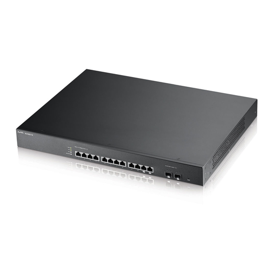
H A PT ER Getting to Know Your Switch 1.1 Introduction This chapter introduces the main features and applications of the Switch. The XS1920 Series consist of the following models at the time of writing: • XS1920-12 The Switch is a 10G Ethernet web-managed switch with layer-2, layer-3, and layer-4 features. -
Page 19: Bridging Example
Switching to higher-speed LANs such as ATM (Asynchronous Transmission Mode) is not feasible for most people due to the expense of replacing all existing Ethernet cables and adapter cards, restructuring your network and complex maintenance. The Switch can provide the same bandwidth XS1920 Series User’s Guide... -
Page 20: Ieee 802.1Q Vlan Application Examples
Shared resources such as a server can be used by all ports in the same VLAN as the server. In the following figure only ports that need access to the server need to be part of VLAN 1. Ports can belong to other VLAN groups too. Figure 4 Shared Server Using VLAN Example XS1920 Series User’s Guide... -
Page 21: Ways To Manage The Switch
Switch to its factory default settings. If you backed up an earlier configuration file, you would not have to totally re-configure the Switch. You could simply restore your last configuration. See Section 3.4 on page 29 for how to reset the Switch. XS1920 Series User’s Guide... -
Page 22: Hardware Installation And Connection
• Four M5 flat head screws and a #2 Philips screwdriver. Failure to use the proper screws may damage the unit. 2.3.1.1 Precautions • Make sure the rack will safely support the combined weight of all the equipment it contains. XS1920 Series User’s Guide... -
Page 23: Attaching The Mounting Brackets To The Switch
Position a mounting bracket (that is already attached to the Switch) on one side of the rack, lining up the two screw holes on the bracket with the screw holes on the side of the rack. XS1920 Series User’s Guide... - Page 24 Figure 6 Mounting the Switch on a Rack Using a #2 Philips screwdriver, install the M5 flat head screws through the mounting bracket holes into the rack. Repeat steps to attach the second mounting bracket on the other side of the rack. XS1920 Series User’s Guide...
-
Page 25: Hardware Panels
Ports 1-10 on the Switch are 100Mbps/1Gbps/10Gbps auto-negotiating, auto-crossover Ethernet ports with full duplex support. An auto-negotiating port can detect and adjust to the optimum Ethernet speed of the connected device. Auto-1000M / Full-Duplex supports Ethernet and fiber connections at 100Mbps or XS1920 Series User’s Guide... -
Page 26: Sfp/Sfp+ Slots
3.1.2.1 Transceiver Installation Use the following steps to install a mini-GBIC transceiver (SFP+ module). Insert the transceiver into the slot with the exposed section of PCB board facing down. Press the transceiver firmly until it clicks into place. XS1920 Series User’s Guide... - Page 27 Remove the fiber optic cables from the transceiver. Open the transceiver’s latch (latch styles vary). Pull the transceiver out of the slot. Figure 10 Removing the Fiber Optic Cables Figure 11 Opening the Transceiver’s Latch Example Figure 12 Transceiver Removal Example XS1920 Series User’s Guide...
-
Page 28: Rear Panel
To connect power to the Switch, insert the female end of the power cord to the AC power receptacle on the rear panel. Connect the other end of the supplied power cord to a power outlet. Make sure that no objects obstruct the airflow of the fans (located on the side of the unit). XS1920 Series User’s Guide... -
Page 29: Leds
This means that you will lose all configurations that you had previously and the default Switch IP address, user name and password will be reset to 192.168.1.1, admin and 1234 respectively. XS1920 Series User’s Guide... - Page 30 Note: If you want to access the Switch web configurator again, you may need to change the IP address of your computer to be in the same subnet as that of the default Switch IP address (192.168.1.1). XS1920 Series User’s Guide...
-
Page 31: Technical Reference
Technical Reference... -
Page 32: The Web Configurator
The login screen appears. The default username is admin and associated default password is 1234. The date and time display as shown if you have not configured a time server nor manually entered a time and date in the General Setup screen. XS1920 Series User’s Guide... -
Page 33: The Status Screen
A - Click the menu items to open submenu links, and then click on a submenu link to open the screen in the main window. B, C, D, E - These are quick links which allow you to perform certain tasks no matter which screen you are currently working in. XS1920 Series User’s Guide... - Page 34 This link takes you to a screen where you can configure general identification information about the Switch. Switch Setup This link takes you to a screen where you can set up global Switch parameters such as VLAN type, GARP and priority queues. XS1920 Series User’s Guide...
- Page 35 Authentication Dial-In User Service) or TACACS+ (Terminal Access Controller Access- Control System Plus). IP Source Guard This link takes you to screens where you can configure filtering of unauthorized DHCP and ARP packets in your network. XS1920 Series User’s Guide...
- Page 36 This link takes you to a screen where you can copy attributes of one port to other ports. Neighbor Table This link takes you to a screen where you can view the IPv6 neighbor table which includes index, interface, neighbor address, MAC address, status and type. XS1920 Series User’s Guide...
-
Page 37: Change Your Password
Note: Use the Save link when you are done with a configuration session. 4.5 Switch Lockout You could block yourself (and all others) from managing the Switch if you do one of the following: Delete the management VLAN (default is VLAN 1). XS1920 Series User’s Guide... -
Page 38: Resetting The Switch
Figure 17 Web Configurator: Logout Screen 4.8 Help The web configurator’s online help has descriptions of individual screens and some supplementary information. Click the Help link from a web configurator screen to view an online help description of that screen. XS1920 Series User’s Guide... -
Page 39: Initial Setup Example
In this example, you want to configure port 1 as a member of VLAN 2. Figure 18 Initial Setup Network Example: VLAN Click Advanced Application > VLAN > VLAN Configuration in the navigation panel and click the Static VLAN Setup link. XS1920 Series User’s Guide... -
Page 40: Setting Port Vid
VLAN group that the tag defines. In the example network, configure 2 as the port VID on port 1 so that any untagged frames received on that port get sent to VLAN 2. XS1920 Series User’s Guide... -
Page 41: Configuring Switch Management Ip Address
Connect your computer to any Ethernet port on the Switch. Make sure your computer is in the same subnet as the Switch. Open your web browser and enter 192.168.1.1 (the default IP address) in the address bar to access the web configurator. See Section 4.2 on page 32 for more information. XS1920 Series User’s Guide... - Page 42 This is the same as the VLAN ID you configure in the Static VLAN screen. Click Add to save your changes back to the run- time memory. Settings in the run-time memory are lost when the Switch’s power is turned off. XS1920 Series User’s Guide...
-
Page 43: Tutorials
1 and 100 DHCP Client (B) 1 and 100 DHCP Client (C) 1 and 100 Access the Switch through http://192.168.1.1 by default. Log into the Switch by entering the username (default: admin) and password (default: 1234). XS1920 Series User’s Guide... - Page 44 Go to Advanced Application > VLAN > VLAN Configuration > VLAN Port Setup, and set the PVID of the ports 5, 6 and 7 to 100. This tags untagged incoming frames on ports 5, 6 and 7 with the tag 100. XS1920 Series User’s Guide...
- Page 45 Go to Advanced Application > IP Source Guard > DHCP snooping > Configure, activate and specify VLAN 100 as the DHCP VLAN as shown. Click Apply. Tutorial: Specify DHCP VLAN Figure 24 Click the Port link at the top right corner. XS1920 Series User’s Guide...
- Page 46 6 or 7, the computer will not able to get an IP address. 10 To check if DHCP snooping works, go to Advanced Application > IP Source Guard, you should see an IP assignment with the type DHCP-Snooping as shown. XS1920 Series User’s Guide...
-
Page 47: How To Use Dhcp Relay On The Switch
Follow the steps below to configure port 2 as a member of VLAN 102. Access the web configurator through the Switch’s management port. Go to Basic Setting > Switch Setup and set the VLAN type to 802.1Q. Click Apply to save the settings to the run-time memory. XS1920 Series User’s Guide... - Page 48 Clear the TX Tagging check box to set the Switch to remove VLAN tags before sending. Click Add to save the settings to the run-time memory. Settings in the run-time memory are lost when the Switch’s power is turned off. Figure 30 Tutorial: Create a Static VLAN XS1920 Series User’s Guide...
-
Page 49: Configuring Dhcp Relay
Click IP Application > DHCP > DHCPv4 and then the Global link to open the DHCP Relay screen. Select the Active check box. Enter the DHCP server’s IP address (192.168.2.3 in this example) in the Remote DHCP Server 1 field. Select default1 or default2 in the Option 82 Profile field. XS1920 Series User’s Guide... -
Page 50: Troubleshooting
You configured the correct VLAN ID, port number and system name for DHCP relay on both the DHCP server and the Switch. You clicked the Save link on the Switch to have your settings take effect. XS1920 Series User’s Guide... -
Page 51: Zon Utility, Zon Neighbor Management And Port Status
ZON Utility screen and you can perform tasks like basic configuration of the devices and batch firmware upgrade in it. You can download the ZON Utility at www.zyxel.com and install it on a PC. The following figure shows the ZON Utility screen. XS1920 Series User’s Guide... -
Page 52: Neighbor Screen
(turn the power off and then back on again), and reset to factory default settings in the Neighbor Management screen. For more information on LLDP, see (Section 34.3 on page 268). Click Status > Neighbor to see the following screen. Status > Neighbor Figure 35 XS1920 Series User’s Guide... -
Page 53: Port Status Summary
This shows the MAC address of the neighbor device in the remote network. This field will show “-” for non-ZyXEL devices. 7.4 Port Status Summary To view the port statistics, click Status in all web configurator screens to display the Status screen as shown next. Figure 36 Status XS1920 Series User’s Guide... -
Page 54: Status: Port Details
7.4.1 Status: Port Details Click a number in the Port column in the Status screen to display individual port statistics. Use this screen to check status and detailed performance data about an individual port on the Switch. XS1920 Series User’s Guide... - Page 55 If STP is disabled, this field displays FORWARDING if the link is up, otherwise, it displays STOP. LACP This field shows if LACP is enabled on this port or not. TxPkts This field shows the number of transmitted frames on this port XS1920 Series User’s Guide...
- Page 56 This field shows the number of packets (including bad packets) received that were between 65 and 127 octets in length. 128-255 This field shows the number of packets (including bad packets) received that were between 128 and 255 octets in length. XS1920 Series User’s Guide...
- Page 57 1024 and 1518 octets in length. Giant This field shows the number of packets (including bad packets) received that were between 1519 octets and the maximum frame size. The maximum frame size varies depending on your switch model. XS1920 Series User’s Guide...
-
Page 58: Basic Setting
(Section 8.8 on page 71) to view IPv6 status and IPv6 configuration. 8.2 System Information In the navigation panel, click Basic Setting > System Info to display the screen as shown. You can check the firmware version number. XS1920 Series User’s Guide... - Page 59 CPU utilization. Memory Memory Utilization shows how much DRAM memory is available and in use. It also displays Utilization the current percentage of memory utilization. Name This field displays the name of memory pool. XS1920 Series User’s Guide...
-
Page 60: General Setup
Error is displayed. 8.3 General Setup Use this screen to configure general settings such as the system name and time. Click Basic Setting > General Setup in the navigation panel to display the screen as shown. XS1920 Series User’s Guide... - Page 61 60 seconds. If you select a timeserver that is unreachable, then this screen will appear locked for 60 seconds. Please wait. Current Time This field displays the time you open this menu (or refresh the menu). XS1920 Series User’s Guide...
-
Page 62: Introduction To Vlans
When properly configured, VLAN prevents one subscriber from accessing the network resources of another on the same LAN, thus a user will not see the printers and hard disks of another user in the same building. XS1920 Series User’s Guide... -
Page 63: Switch Setup Screen
Aging Time Enter a time from 10 to 1000000 seconds. This is how long all dynamically learned MAC addresses remain in the MAC address table before they age out (and must be relearned). XS1920 Series User’s Guide... - Page 64 Save link on the top navigation panel to save your changes to the non-volatile memory when you are done configuring. Cancel Click Cancel to reset the fields. XS1920 Series User’s Guide...
-
Page 65: Ip Setup
Click this to renew the dynamic IP address. Release Click this to release the dynamic IP address. 8.6.2 IP Status Details Click the index link in the IP Status screen to view further details on this IP address. XS1920 Series User’s Guide... - Page 66 This shows whether ths IP address is dynamically assigned from a DHCP server or manually assigned (Static or DHCP). This is the VLAN identification number to which an IP routing domain belongs. IP Address This is the IP address of your Switch in dotted decimal notation for example 192.168.1.1. XS1920 Series User’s Guide...
-
Page 67: Ip Configuration
You can configure up to 32 IP domains which are used to access and manage the Switch from the ports belonging to the pre-defined VLAN(s). Click IP Setup > IP Configuration to display the next screen. XS1920 Series User’s Guide... - Page 68 Enter the IP address of your Switch in dotted decimal notation for example 192.168.1.1. IP Subnet Mask Enter the IP subnet mask of your Switch in dotted decimal notation for example 255.255.255.0. Enter the VLAN identification number to which an IP routing domain belongs. XS1920 Series User’s Guide...
-
Page 69: Port Setup
Click Cancel to clear the selected check boxes in the Delete column. 8.7 Port Setup Use this screen to configure Switch port settings. Click Basic Setting > Port Setup in the navigation panel to display the configuration screen. Figure 46 Basic Setting > Port Setup XS1920 Series User’s Guide... - Page 70 Save link on the top navigation panel to save your changes to the non-volatile memory when you are done configuring. Cancel Click Cancel to begin configuring this screen afresh. XS1920 Series User’s Guide...
-
Page 71: Interface Setup
Switch. The name is from a combination of the interface type and ID number. Delete Check the rules that you want to remove in the delete column, then click the Delete button. Cancel Click Cancel to clear the Delete check boxes. XS1920 Series User’s Guide... -
Page 72: Ipv6
This field displays whether the IPv6 interface is activated or not. 8.9.1 IPv6 Interface Status Use this screen to view a specific IPv6 interface status and detailed information. Click an interface index number in the Basic Setting > IPv6 screen. The following screen opens. XS1920 Series User’s Guide... - Page 73 If the bucket is full, subsequent error messages are Size suppressed. ICMPv6 Rate This field displays the time period (in milliseconds) during which ICMPv6 error messages of Limit Error up to the bucket size can be transmitted. 0 means no limit. Interval XS1920 Series User’s Guide...
- Page 74 This field displays how long (in seconds) that the global address remains preferred. Lifetime Valid This field displays how long (in seconds) that the global address is valid. Lifetime This field displays the DNS server address assigned by the DHCPv6 server. XS1920 Series User’s Guide...
-
Page 75: Ipv6 Configuration
Click the link to go to a screen where you can configure the IPv6 global address for an Global interface. Address Setup IPv6 Neighbor Discovery IPv6 Click the link to go to a screen where you can configure the IPv6 neighbor discovery settings. Neighbor Discovery Setup XS1920 Series User’s Guide... -
Page 76: Ipv6 Global Setup
Use this screen to turn on or off an IPv6 interface and enable stateless autoconfiguration on it. Click the link next to IPv6 Interface Setup in the IPv6 Configuration screen to display the screen as shown next. XS1920 Series User’s Guide... -
Page 77: Ipv6 Link-Local Address Setup
A link-local unicast address has a predefined prefix of fe80::/10. Use this screen to configure the interface’s link-local address and default gateway. Click the link next to IPv6 Link-Local Address Setup in the IPv6 Configuration screen to display the screen as shown next. XS1920 Series User’s Guide... -
Page 78: Ipv6 Global Address Setup
8.9.6 IPv6 Global Address Setup Use this screen to configure the interface’s IPv6 global address. Click the link next to IPv6 Global Address Setup in the IPv6 Configuration screen to display the screen as shown next. XS1920 Series User’s Guide... -
Page 79: Ipv6 Neighbor Discovery Setup
8.9.7 IPv6 Neighbor Discovery Setup Use this screen to configure neighbor discovery settings for each interface. Click the link next to IPv6 Neighbor Discovery Setup in the IPv6 Configuration screen to display the screen as shown next. XS1920 Series User’s Guide... -
Page 80: Ipv6 Router Discovery Setup
8.9.8 IPv6 Router Discovery Setup Use this screen to configure router discovery settings for each interface. Click the link next to IPv6 Router Discovery Setup in the IPv6 Configuration screen to display the screen as shown next. XS1920 Series User’s Guide... - Page 81 Click Clear to reset the fields to the factory defaults. Index This is the interface index number. Click on an index number to change the settings. Interface This is the name of the IPv6 interface you created. XS1920 Series User’s Guide...
-
Page 82: Ipv6 Prefix Setup
Set the IPv6 prefix that the Switch includes in router advertisements for this interface. Prefix Length Set the prefix length that the Switch includes in router advertisements for this interface. Valid Lifetime Specify how long (from 0 to 4294967295 seconds) the prefix is valid for on-link determination. XS1920 Series User’s Guide... -
Page 83: Ipv6 Neighbor Setup
Click the link next to IPv6 Neighbor Setup in the IPv6 Configuration screen to display the screen as shown next. Figure 58 Basic Setting > IPv6 > IPv6 Configuration > IPv6 Neighbor Setup XS1920 Series User’s Guide... -
Page 84: Dhcpv6 Client Setup
Use this screen to configure the Switch’s DHCP settings when it is acting as a DHCPv6 client. Click the link next to IPv6 Neighbor Setup in the IPv6 Configuration screen to display the screen as shown next. XS1920 Series User’s Guide... - Page 85 This field displays whether the Switch obtains a list of domain names from the DHCP server. Information This field displays the time interval (in seconds) at which the Switch exchanges other Refresh configuration information with a DHCPv6 server again. Minimum XS1920 Series User’s Guide...
-
Page 86: Vlan
A tagged VLAN uses an explicit tag (VLAN ID) in the MAC header to identify the VLAN membership of a frame across bridges - they are not confined to the switch on which they were created. The XS1920 Series User’s Guide... - Page 87 Switches join VLANs by making a declaration. A declaration is made by issuing a Join message using GARP. Declarations are withdrawn by issuing a Leave message. A Leave All message terminates all registrations. GARP timers set declaration timeout values. XS1920 Series User’s Guide...
-
Page 88: Port Vlan Trunking
VLAN groups in the end devices (A and B). C, D and E automatically allow frames with VLAN group tags 1 and 2 (VLAN groups that are unknown to those switches) to pass through their VLAN trunking port(s). Figure 60 Port VLAN Trunking XS1920 Series User’s Guide... -
Page 89: Vlan Status
VLAN(s) in the list below. Leave this field blank and click Search to display all VLANs configured on the Switch. The Number of This is the number of VLANs configured on the Switch. VLAN XS1920 Series User’s Guide... -
Page 90: Vlan Details
T, an untagged port is marked as U and ports not participating in a VLAN are marked as “–“. Elapsed Time This field shows how long it has been since a normal VLAN was registered or a static VLAN was set up. XS1920 Series User’s Guide... -
Page 91: Private Vlan Status
These fields show information for the all private VLANs. See also Advanced Application > Status Private VLAN. Primary This field shows the primary VLAN ID in a private VLAN. VLAN Secondary This field shows the secondary VLAN ID in a private VLAN. VLAN XS1920 Series User’s Guide... -
Page 92: Vlan Configuration
Click Click Here to configure the MAC Based VLAN for the Switch. 9.5 Configure a Static VLAN Use this screen to configure a static VLAN for the Switch. Click Static VLAN in the VLAN Status screen to display the screen as shown next. XS1920 Series User’s Guide... - Page 93 64 printable characters. VLAN Group ID Enter the VLAN ID for this static entry; the valid range is between 1 and 4094. VLAN Type Select Normal (static) or Private. For Private VLANs, select Primary, Isolated or Community. XS1920 Series User’s Guide...
-
Page 94: Configure Vlan Port Settings
Click Cancel to clear the Delete check boxes. 9.6 Configure VLAN Port Settings Use the VLAN Port Setting screen to configure the static VLAN (IEEE 802.1Q) settings on a port. Click the VLAN Port Setup link in the VLAN Status screen. XS1920 Series User’s Guide... - Page 95 VLAN group that the tag defines. Enter a number between 1and 4094 as the port VLAN ID. GVRP Select this check box to allow GVRP on this port. XS1920 Series User’s Guide...
-
Page 96: Subnet Based Vlans
3 and VID of 300 for traffic received from IP subnet 10.1.1.0/24 (data services). All untagged incoming frames will be classified based on their source IP subnet and prioritized accordingly. That is video services receive the highest priority and data the lowest. XS1920 Series User’s Guide... -
Page 97: Configuring Subnet Based Vlan
Click Subnet Based VLAN in the VLAN Port Setting screen to display the configuration screen as shown. Note: Subnet based VLAN applies to un-tagged packets and is applicable only when you use IEEE 802.1Q tagged VLAN. Figure 69 Advanced Application > VLAN > VLAN Port Setting > Subnet Based VLAN XS1920 Series User’s Guide... -
Page 98: Protocol Based Vlans
VLAN. One advantage of using protocol based VLANs is that priority can be assigned to traffic of the same protocol. Note: Protocol based VLAN applies to un-tagged packets and is applicable only when you use IEEE 802.1Q tagged VLAN. XS1920 Series User’s Guide... -
Page 99: Configuring Protocol Based Vlan
Click Protocol Based VLAN Setup in the VLAN Configuration screen to display the configuration screen as shown. Note: Protocol-based VLAN applies to un-tagged packets and is applicable only when you use IEEE 802.1Q tagged VLAN. Figure 71 Advanced Application > VLAN > VLAN Configuration > Protocol Based VLAN Setup XS1920 Series User’s Guide... -
Page 100: Voice Vlan
You can set priority level to the Voice VLAN and add MAC address of IP phones from specific manufacturers by using its ID from the Organizationally Unique Identifiers (OUI). Click Voice VLAN in the VLAN Configuration screen to display the configuration screen as shown. XS1920 Series User’s Guide... - Page 101 Click Add to save your changes to the Switch’s run-time memory. The Switch loses these changes if it is turned off or loses power, so use the Save link on the top navigation panel to save your changes to the non-volatile memory when you are done configuring. XS1920 Series User’s Guide...
-
Page 102: Mac-Based Vlan
MAC-based VLAN entry in the same screen. Click MAC-based VLAN in the VLAN Configuration window to see the following screen. Figure 73 Advanced Application > VLAN > VLAN Configuration > MAC-based VLAN Setup XS1920 Series User’s Guide... -
Page 103: Port-Based Vlan Setup
Note: In screens (such as IP Setup and Filtering) that require a VID, you must enter 1 as the VID. The port-based VLAN setup screen is shown next. The CPU management port forms a VLAN with all Ethernet ports. XS1920 Series User’s Guide... -
Page 104: Port-Based Vlan
Select Port Based as the VLAN Type in the Basic Setting > Switch Setup screen. Figure 74 Basic Setting > Switch Setup (Port Based) Then click Advanced Application > VLAN from the navigation panel to display the next screen. Figure 75 Port Based VLAN Setup (All Connected) XS1920 Series User’s Guide... - Page 105 CPU refers to the Switch management port. By default it forms a VLAN with all Ethernet ports. If it does not form a VLAN with a particular port then the Switch cannot be managed from that port. XS1920 Series User’s Guide...
-
Page 106: Technical Reference
Type the VLAN ID of an existing VLAN. In our example we already created a static VLAN with an ID of 5. Type 5. Leave the priority set to 0 and click Add. Figure 77 Protocol Based VLAN Configuration Example To add more ports to this protocol based VLAN. XS1920 Series User’s Guide... - Page 107 Chapter 9 VLAN Click the index number of the protocol based VLAN entry. Click 1 Change the value in the Port field to the next port you want to add. Click Add. XS1920 Series User’s Guide...
-
Page 108: Static Mac Forward Setup
Switch. See Chapter 19 on page 156 for more information on port security. Click Advanced Application > Static MAC Forwarding in the navigation panel to display the configuration screen as shown. XS1920 Series User’s Guide... - Page 109 This field displays the port where the MAC address shown in the next field will be forwarded. Delete Click Delete to remove the selected entry from the summary table. Cancel Click Cancel to clear the Delete check boxes. XS1920 Series User’s Guide...
-
Page 110: Static Multicast Forward Setup
VLAN group. Figure shows frames being forwarded to devices connected to port 3. Figure 81 shows frames being forwarded to ports 2 and 3 within VLAN group 4. Figure 79 No Static Multicast Forwarding XS1920 Series User’s Guide... -
Page 111: Configuring Static Multicast Forwarding
Use this screen to configure rules to forward specific multicast frames, such as streaming or control frames, to specific port(s). Click Advanced Application > Static Multicast Forwarding to display the configuration screen as shown. Figure 82 Advanced Application > Static Multicast Forwarding XS1920 Series User’s Guide... - Page 112 This field displays the port(s) within a identified VLAN group to which frames containing the specified multicast MAC address will be forwarded. Delete Click Delete to remove the selected entry from the summary table. Cancel Click Cancel to clear the Delete check boxes. XS1920 Series User’s Guide...
-
Page 113: Filtering
12.2 Configure a Filtering Rule Use this screen to create rules for traffic going through the Switch. Click Advanced Application > Filtering in the navigation panel to display the screen as shown next. Figure 83 Advanced Application > Filtering XS1920 Series User’s Guide... - Page 114 This field displays the VLAN group identification number. Delete Check the rule(s) that you want to remove in the Delete column and then click the Delete button. Cancel Click Cancel to clear the selected checkbox(es) in the Delete column. XS1920 Series User’s Guide...
-
Page 115: Spanning Tree Protocol
(R)STP detects and breaks network loops and provides backup links between switches, bridges or routers. It allows a switch to interact with other (R)STP -compliant switches in your network to ensure that only one path exists between any two stations on the network. XS1920 Series User’s Guide... -
Page 116: Stp Terminology
Protocol Data Units) transmitted from the root bridge. If a bridge does not get a Hello BPDU after a predefined interval (Max Age), the bridge assumes that the link to the root bridge is down. This bridge then initiates negotiations with other bridges to reconfigure the network to re-establish a valid network topology. XS1920 Series User’s Guide... -
Page 117: Stp Port States
Figure 84 MRSTP Network Example Multiple STP Multiple Spanning Tree Protocol (IEEE 802.1s) is backward compatible with STP/RSTP and addresses the limitations of existing spanning tree protocols (STP and RSTP) in networks to include the following features: XS1920 Series User’s Guide... -
Page 118: Spanning Tree Protocol Status Screen
Use the Spanning Tree Configuration screen to activate one of the STP modes on the Switch. Click Configuration in the Advanced Application > Spanning Tree Protocol. Figure 86 Advanced Application > Spanning Tree Protocol > Configuration XS1920 Series User’s Guide... -
Page 119: Configure Rapid Spanning Tree Protocol
Use this screen to configure RSTP settings, see Section 13.1 on page 115 for more information on RSTP. Click RSTP in the Advanced Application > Spanning Tree Protocol screen. Figure 87 Advanced Application > Spanning Tree Protocol > RSTP XS1920 Series User’s Guide... - Page 120 Priority decides which port should be disabled when more than one port forms a loop in a switch. Ports with a higher priority numeric value are disabled first. The allowed range is between 0 and 255 and the default value is 128. XS1920 Series User’s Guide...
-
Page 121: Rapid Spanning Tree Protocol Status
(second) message. The root bridge determines Hello Time, Max Age and Forwarding Delay. Max Age (second) This is the maximum time (in seconds) the Switch can wait without receiving a configuration message before attempting to reconfigure. XS1920 Series User’s Guide... -
Page 122: Configure Multiple Rapid Spanning Tree Protocol
This is the time since the spanning tree was last reconfigured. Change 13.5 Configure Multiple Rapid Spanning Tree Protocol To configure MRSTP, click MRSTP in the Advanced Application > Spanning Tree Protocol screen. See Section 13.1 on page 115 for more information on MRSTP. XS1920 Series User’s Guide... - Page 123 Select a value from the drop-down list box. The lower the numeric value you assign, the higher the priority for this bridge. Bridge Priority determines the root bridge, which in turn determines Hello Time, Max Age and Forwarding Delay. XS1920 Series User’s Guide...
-
Page 124: Multiple Rapid Spanning Tree Protocol Status
Click Advanced Application > Spanning Tree Protocol in the navigation panel to display the status screen as shown next. See Section 13.1 on page 115 for more information on MRSTP. Note: This screen is only available after you activate MRSTP on the Switch. XS1920 Series User’s Guide... -
Page 125: Configure Multiple Spanning Tree Protocol
This is the time since the spanning tree was last reconfigured. Change 13.6 Configure Multiple Spanning Tree Protocol To configure MSTP, click MSTP in the Advanced Application > Spanning Tree Protocol screen. Section on page 117 for more information on MSTP. XS1920 Series User’s Guide... - Page 126 Select this to activate MSTP on the Switch. Clear this to disable MSTP on the Switch. Note: You must also activate Multiple Spanning Tree in the Advanced Application > Spanning Tree Protocol > Configuration screen to enable MSTP on the Switch. XS1920 Series User’s Guide...
- Page 127 Use this row only if you want to make some settings the same for all ports. Use this row first to set the common settings and then make adjustments on a port-by-port basis. Note: Changes in this row are copied to all the ports as soon as you make them. XS1920 Series User’s Guide...
-
Page 128: Multiple Spanning Tree Port Configuration
Click Advanced Application > Spanning Tree Protocol > MSTP > Port in the navigation panel to display the status screen as shown next. See Section on page 117 for more information on MSTP. Figure 92 Advanced Application > Spanning Tree Protocol > MSTP > Port XS1920 Series User’s Guide... -
Page 129: Multiple Spanning Tree Protocol Status
Click Advanced Application > Spanning Tree Protocol in the navigation panel to display the status screen as shown next. See Section on page 117 for more information on MSTP. Note: This screen is only available after you activate MSTP on the Switch. XS1920 Series User’s Guide... - Page 130 This is the path cost from the root port on this Switch to the root switch. Port ID This is the priority and number of the port on the Switch through which this Switch must communicate with the root of the Spanning Tree. XS1920 Series User’s Guide...
-
Page 131: Technical Reference
The following figure shows a network example where two VLANs are configured on the two switches. If the switches are using STP or RSTP, the link for VLAN 2 will be blocked as STP and RSTP allow only one link in the network and block the redundant link. XS1920 Series User’s Guide... -
Page 132: Mst Region
Devices that belong to the same MST region are configured to have the same MSTP configuration identification settings. These include the following parameters: • Name of the MST region • Revision level as the unique number for the MST region XS1920 Series User’s Guide... -
Page 133: Mst Instance
MST instance are members of the CIST. In an MSTP-enabled network, there is only one CIST that runs between MST regions and single spanning tree devices. A network may contain multiple MST regions and other network segments running RSTP. Figure 97 MSTP and Legacy RSTP Network Example XS1920 Series User’s Guide... -
Page 134: Bandwidth Control
(Section 14.2 on page 134) to limit the bandwidth for traffic going through the Switch. 14.2 Bandwidth Control Setup Click Advanced Application > Bandwidth Control in the navigation panel to bring up the screen as shown next. XS1920 Series User’s Guide... - Page 135 Save link on the top navigation panel to save your changes to the non-volatile memory when you are done configuring. Cancel Click Cancel to reset the fields. XS1920 Series User’s Guide...
-
Page 136: Broadcast Storm Control
(DLF) packets the Switch receives per second on the ports. 15.2 Broadcast Storm Control Setup Click Advanced Application > Broadcast Storm Control in the navigation panel to display the screen as shown next. XS1920 Series User’s Guide... - Page 137 Save link on the top navigation panel to save your changes to the non-volatile memory when you are done configuring. Cancel Click Cancel to reset the fields. XS1920 Series User’s Guide...
-
Page 138: Mirroring
Click Advanced Application > Mirroring in the navigation panel to display the Mirroring screen. Use this screen to select a monitor port and specify the traffic flow to be copied to the monitor port. Figure 100 Advanced Application > Mirroring XS1920 Series User’s Guide... - Page 139 Save link on the top navigation panel to save your changes to the non-volatile memory when you are done configuring. Cancel Click Cancel to reset the fields. XS1920 Series User’s Guide...
-
Page 140: Link Aggregation
When you enable LACP link aggregation on a port, the port can automatically negotiate with the ports at the remote end of a link to establish trunk groups. LACP also allows port redundancy, that XS1920 Series User’s Guide... -
Page 141: Link Aggregation Status
17.2 Link Aggregation Status Click Advanced Application > Link Aggregation in the navigation panel. The Link Aggregation Status screen displays by default. See Section 17.1 on page 140 for more information. Figure 101 Advanced Application > Link Aggregation Status XS1920 Series User’s Guide... -
Page 142: Link Aggregation Setting
LACP - if the ports are configured to join a trunk group via LACP. 17.3 Link Aggregation Setting Click Advanced Application > Link Aggregation > Link Aggregation Setting to display the screen shown next. See Section 17.1 on page 140 for more information on link aggregation. XS1920 Series User’s Guide... - Page 143 This is the only screen you need to configure to enable static link aggregation. Aggregation Setting Group ID The field identifies the link aggregation group, that is, one logical link containing multiple ports. Active Select this option to activate a trunk group. XS1920 Series User’s Guide...
-
Page 144: Link Aggregation Control Protocol
Click Cancel to begin configuring this screen afresh. 17.4 Link Aggregation Control Protocol Click Advanced Application > Link Aggregation > Link Aggregation Setting > LACP to display the screen shown next. See Section on page 140 for more information on dynamic link aggregation. XS1920 Series User’s Guide... - Page 145 Link Aggregation Control Protocol (LACP). The smaller the number, the higher the priority level. Group ID The field identifies the link aggregation group, that is, one logical link containing multiple ports. LACP Active Select this option to enable LACP for a trunk. XS1920 Series User’s Guide...
-
Page 146: Technical Reference
Aggregation Setting. In this screen activate trunk group T1, select the traffic distribution algorithm used by this group and select the ports that should belong to this group as shown in the figure below. Click Apply when you are done. XS1920 Series User’s Guide... - Page 147 Chapter 17 Link Aggregation Figure 105 Trunking Example - Configuration Screen EXAMPLE Your trunk group 1 (T1) configuration is now complete. XS1920 Series User’s Guide...
-
Page 148: Port Authentication
At the time of writing, IEEE 802.1x is not supported by all operating systems. See your operating system documentation. If your operating system does not support 802.1x, then you may need to install 802.1x client software. XS1920 Series User’s Guide... -
Page 149: Mac Authentication
MAC address of the client connecting to a port on the Switch along with a password configured specifically for MAC authentication on the Switch. Figure 107 MAC Authentication Process New Connection Authentication Request Authentication Reply Session Granted/Denied XS1920 Series User’s Guide... -
Page 150: Port Authentication Configuration
18.3 Activate IEEE 802.1x Security Use this screen to activate IEEE 802.1x security. In the Port Authentication screen click 802.1x to display the configuration screen as shown. Figure 109 Advanced Application > Port Authentication > 802.1x XS1920 Series User’s Guide... -
Page 151: Guest Vlan
VLAN. That is, unauthenticated users can have access to limited network resources in the same guest VLAN, such as the Internet. The rights granted to the Guest VLAN depends on how the network administrator configures switches or routers with the guest network feature. XS1920 Series User’s Guide... - Page 152 Use this row only if you want to make some settings the same for all ports. Use this row first to set the common settings and then make adjustments on a port-by-port basis. Changes in this row are copied to all the ports as soon as you make them. XS1920 Series User’s Guide...
-
Page 153: Activate Mac Authentication
Cancel Click Cancel to begin configuring this screen afresh. 18.3.2 Activate MAC Authentication Use this screen to activate MAC authentication. In the Port Authentication screen click MAC Authentication to display the configuration screen as shown. XS1920 Series User’s Guide... - Page 154 MAC address table. Note: If the Aging Time in the Switch Setup screen is set to a lower value, then it supersedes this setting. See Section 8.5 on page Port This field displays a port number. XS1920 Series User’s Guide...
- Page 155 Save link on the top navigation panel to save your changes to the non-volatile memory when you are done configuring. Cancel Click Cancel to begin configuring this screen afresh. XS1920 Series User’s Guide...
-
Page 156: Port Security
156) to enable port security and disable MAC address learning. You can also enable the port security feature on a port. 19.2 Port Security Setup Click Advanced Application > Port Security in the navigation panel to display the screen as shown. XS1920 Series User’s Guide... - Page 157 Use this row only if you want to make some settings the same for all ports. Use this row first to set the common settings and then make adjustments on a port-by-port basis. Note: Changes in this row are copied to all the ports as soon as you make them. XS1920 Series User’s Guide...
-
Page 158: Vlan Mac Address Limit
Table 68 Advanced Application > Port Security > VLAN MAC Address Limit LABEL DESCRIPTION Active Select this option to activate this rule. Port Enter the number of the port to which this rule is applied. Enter the VLAN identification number. XS1920 Series User’s Guide... - Page 159 This is the maximum number of MAC addresses which a port can learn in a VLAN. Delete Check the rule(s) that you want to remove in the Delete column and then click the Delete button. Cancel Click Cancel to clear the selected checkbox(es) in the Delete column. XS1920 Series User’s Guide...
-
Page 160: Time Range
Periodic is recurrence of a time range and doesn’t have an end time. 20.2 Time Range Setup Click Advanced Application > Time Range in the navigation panel to display the screen as shown. Figure 115 Advanced Application > Time Range XS1920 Series User’s Guide... - Page 161 You can delete this time range by clicking the check box of this time range rule and click Delete button below. Delete Check the rule(s) that you want to remove in the Delete column and then click the Delete button. Cancel Click Cancel to clear the selected checkbox(es) in the Delete column. XS1920 Series User’s Guide...
-
Page 162: Classifier
Status screen to view a summary of the classifiers configured. To configure policy rules, refer to Chapter 22 on page 171. Click Advanced Application > Classifier in the navigation panel to display the configuration Status screen as shown. XS1920 Series User’s Guide... -
Page 163: Classifier Configuration
Select Classifier, type a classifier name in the text box, then click Clear to clear the matched count for that classifier. 21.3 Classifier Configuration Click Classifier Configuration in the Classifier Status screen to display the configuration screen as shown. XS1920 Series User’s Guide... - Page 164 Chapter 21 Classifier Figure 117 Advanced Application > Classifier Configuration XS1920 Series User’s Guide...
- Page 165 Mask Manually type the source MAC mask to which the rule should be applied. You may choose one MAC mask only or all masks (Any). Layer 3 Specify the fields below to configure a layer-3 classifier. XS1920 Series User’s Guide...
- Page 166 Save link on the top navigation panel to save your changes to the non-volatile memory when you are done configuring. Cancel Click Cancel to begin configuring this screen afresh. Clear Click Clear to set the above fields back to the factory defaults. XS1920 Series User’s Guide...
-
Page 167: Viewing And Editing Classifier Configuration
ETHERNET TYPE PROTOCOL NUMBER IP ETHII 0800 X.75 Internet 0801 NBS Internet 0802 ECMA Internet 0803 Chaosnet 0804 X.25 Level 3 0805 XNS Compat 0807 Banyan Systems 0BAD BBN Simnet 5208 IBM SNA 80D5 AppleTalk AARP 80F3 XS1920 Series User’s Guide... -
Page 168: Classifier Global Setting
Layer-4 items have the highest priority. Logging Active Select this to create a log when packets match a classifier rule during a defined time interval. XS1920 Series User’s Guide... -
Page 169: Classifier Example
The following screen shows an example where you configure a classifier that identifies all traffic from MAC address 00:50:ba:ad:4f:81 on port 2. After you have configured a classifier, you can configure a policy (in the Policy screen) to define action(s) on the classified traffic flow. XS1920 Series User’s Guide... - Page 170 Chapter 21 Classifier Figure 120 Classifier: Example EXAMPLE XS1920 Series User’s Guide...
-
Page 171: Policy Rule
22.2 Configuring Policy Rules You must first configure a classifier in the Classifier screen. Refer to Section 21.2 on page 162 more information. Click Advanced Applications > Policy Rule in the navigation panel to display the screen as shown. XS1920 Series User’s Guide... - Page 172 Figure 121 Advanced Application > Policy Rule The following table describes the labels in this screen. Table 77 Advanced Application > Policy Rule LABEL DESCRIPTION Active Select this option to enable the policy. Name Enter a descriptive name for identification purposes. XS1920 Series User’s Guide...
- Page 173 802.1 priority field with the inner value. Queue Select No change to keep the frames in the same queue. Select Send the packet to priority queue to put the frames in the designated queue. XS1920 Series User’s Guide...
-
Page 174: Viewing And Editing Policy Configuration
To view a summary of the classifier configuration, scroll down to the summary table at the bottom of the Policy screen. To change the settings of a rule, click a number in the Index field. Figure 122 Advanced Application > Policy Rule: Summary Table XS1920 Series User’s Guide... -
Page 175: Queuing Method
A queue is a given an amount of bandwidth irrespective of the incoming traffic on that port. This queue then moves to the back of the list. The next queue is given XS1920 Series User’s Guide... -
Page 176: Configuring Queuing
Use this screen to set priorities for the queues of the Switch. This distributes bandwidth across the different traffic queues. Click Advanced Application > Queuing Method in the navigation panel. Figure 123 Advanced Application > Queuing Method XS1920 Series User’s Guide... - Page 177 Save link on the top navigation panel to save your changes to the non-volatile memory when you are done configuring. Cancel Click Cancel to begin configuring this screen afresh. XS1920 Series User’s Guide...
-
Page 178: Multicast
(see the IANA website for more information). IGMP Snooping A Switch can passively snoop on IGMP packets transferred between IP multicast routers/switches and IP multicast hosts to learn the IP multicast group membership. It checks IGMP packets passing XS1920 Series User’s Guide... - Page 179 In the following MLD snooping-proxy example, all connected upstream ports (1 ~7) are treated as one interface. The connection between ports 8 and 9 is blocked by STP to break the loop. If there is XS1920 Series User’s Guide...
- Page 180 The following figure shows a network example. The subscriber VLAN (1, 2 and 3) information is hidden from the streaming media server, S. In addition, the multicast VLAN information is only visible to the Switch and S. XS1920 Series User’s Guide...
- Page 181 (in this case, an uplink port on the Switch). If there is another subscriber device connected to this port in the same subscriber VLAN, the receiving port will still be on the list of forwarding destination for the multicast traffic. Otherwise, the Switch removes the receiver port from the forwarding table. XS1920 Series User’s Guide...
-
Page 182: Multicast Setup
Click Advanced Application > Multicast > IPv4 Multicast to display the screen as shown. This screen shows the IPv4 multicast group information. See Section 24.1 on page 178 for more information on multicasting. Figure 127 Advanced Application > Multicast > IPv4 Multicast XS1920 Series User’s Guide... -
Page 183: Igmp Snooping
Click the IGMP Snooping link in the Advanced Application > Multicast > IPv4 Multicast screen to display the screen as shown. See Section 24.1 on page 178 for more information on multicasting. Figure 128 Advanced Application > Multicast > IPv4 Multicast > IGMP Snooping XS1920 Series User’s Guide... - Page 184 This defines how many seconds the Switch waits for an IGMP report before removing an IGMP snooping membership entry when an IGMP leave message is received on this port from a host. XS1920 Series User’s Guide...
-
Page 185: Igmp Snooping Vlan
Click Advanced Application > Multicast > IPv4 Multicast in the navigation panel. Click the IGMP Snooping link and then the IGMP Snooping VLAN link to display the screen as shown. See Section on page 179 for more information on IGMP Snooping VLAN. XS1920 Series User’s Guide... - Page 186 Save link on the top navigation panel to save your changes to the non-volatile memory when you are done configuring. Cancel Click Cancel to reset the fields to your previous configuration. Clear Click Clear to reset the fields to the factory defaults. XS1920 Series User’s Guide...
-
Page 187: Igmp Filtering Profile
To configure additional rule(s) for a profile that you have already added, enter the profile name and specify a different IP multicast address range. Start Address Type the starting multicast IP address for a range of multicast IP addresses that you want to belong to the IGMP filter profile. XS1920 Series User’s Guide... -
Page 188: Ipv6 Multicast Status
This field displays IP multicast group addresses. Group Timout This field displays the time (in seconds) that elapses before the Switch removes a MLD group membership entry if it does not receive report messages from the port. XS1920 Series User’s Guide... -
Page 189: Mld Snooping-Proxy
Cancel Click Cancel to begin configuring this screen afresh. 24.5.2 MLD Snooping-proxy VLAN Click the VLAN link in the Advanced Application > Multicast > IPv6 Multicast > MLD Snooping-proxy screen to display the screen as shown. XS1920 Series User’s Guide... - Page 190 This value should be exactly the same as what’s configured in the connected multicast router. This value is used to calculate the amount of time an MLD snooping membership entry (learned only on the upstream port) can remain in the forwarding table. XS1920 Series User’s Guide...
-
Page 191: Mld Snooping-Proxy Vlan Port Role Setting
Click Cancel to clear the Delete check boxes. 24.5.3 MLD Snooping-proxy VLAN Port Role Setting Click the Port Role Setting link in the Advanced Application > Multicast > IPv6 Multicast > MLD Snooping-proxy > VLAN screen to display the screen as shown. XS1920 Series User’s Guide... - Page 192 (learned on a downstream port) immediately (Immediate) or wait for an MLD report before the leave timeout (Normal) or fast leave timeout (Fast) when an MLD leave message is received on this port from a host. XS1920 Series User’s Guide...
-
Page 193: Mld Snooping-Proxy Vlan Filtering
Use this screen to configure the Switch’s MLD filtering settings. Click the Filtering link in the Advanced Application > Multicast > IPv6 Multicast > MLD Snooping-proxy screen to display the screen as shown. Figure 135 Advanced Application > Multicast > IPv6 Multicast > MLD Snooping-proxy > Filtering XS1920 Series User’s Guide... -
Page 194: Mld Snooping-Proxy Vlan Filtering Profile
Click the Filtering Profile link in the Advanced Application > Multicast > IPv6 Multicast > MLD Snooping-proxy > Filtering screen to display the screen as shown. Figure 136 Advanced Application > Multicast > IPv6 Multicast > MLD Snooping-proxy > Filtering > Filtering Profile XS1920 Series User’s Guide... -
Page 195: General Mvr Configuration
Note: You can create up to five multicast VLANs and up to 256 multicast rules on the Switch. Note: Your Switch automatically creates a static VLAN (with the same VID) when you create a multicast VLAN in this screen. XS1920 Series User’s Guide... - Page 196 Use this row only if you want to make some settings the same for all ports. Use this row first to set the common settings and then make adjustments on a port-by-port basis. Changes in this row are copied to all the ports as soon as you make them. XS1920 Series User’s Guide...
-
Page 197: Mvr Group Configuration
Use this screen to configure MVR IP multicast group address(es). Click the Group Configuration link in the MVR screen. Note: A port can belong to more than one multicast VLAN. However, IP multicast group addresses in different multicast VLANs cannot overlap. XS1920 Series User’s Guide... - Page 198 Delete button to remove the selected entry(ies) from the table. If you delete a multicast VLAN, all multicast groups in this VLAN will also be removed. Cancel Select Cancel to clear the checkbox(es) in the table. XS1920 Series User’s Guide...
-
Page 199: Mvr Configuration Example
To set the Switch to forward the multicast group traffic to the subscribers, configure multicast group settings in the Group Configuration screen. The following figure shows an example where two IPv4 multicast groups (News and Movie) are configured for the multicast VLAN 200. XS1920 Series User’s Guide... - Page 200 Chapter 24 Multicast Figure 141 MVR Group Configuration Example EXAMPLE Figure 142 MVR Group Configuration Example EXAMPLE XS1920 Series User’s Guide...
-
Page 201: Aaa
Switch but user B cannot. The Switch can authorize users based on user accounts configured on the Switch itself or it can use an external server to authorize a large number of users. XS1920 Series User’s Guide... -
Page 202: Aaa Screens
Figure 144 Advanced Application > AAA 25.3 RADIUS Server Setup Use this screen to configure your RADIUS server settings. See Section on page 202 for more information on RADIUS servers and Section 25.6.2 on page 210 for RADIUS attributes utilized by XS1920 Series User’s Guide... - Page 203 Enter the IP address of an external RADIUS server in dotted decimal notation. UDP Port The default port of a RADIUS server for authentication is 1812. You need not change this value unless your network administrator instructs you to do so. XS1920 Series User’s Guide...
-
Page 204: Tacacs+ Server Setup
Use this screen to configure your TACACS+ server settings. See Section on page 202 for more information on TACACS+ servers. Click on the TACACS+ Server Setup link in the AAA screen to view the screen as shown. XS1920 Series User’s Guide... - Page 205 Specify a password (up to 32 alphanumeric characters) as the key to be shared between the external TACACS+ server and the Switch. This key is not sent over the network. This key must be the same on the external TACACS+ server and the Switch. XS1920 Series User’s Guide...
-
Page 206: Aaa Setup
Click Cancel to begin configuring this screen afresh. 25.5 AAA Setup Use this screen to configure authentication and authorization settings on the Switch. Click on the AAA Setup link in the AAA screen to view the screen as shown. XS1920 Series User’s Guide... - Page 207 • Dot1x: Allow an IEEE 802.1x client to have different bandwidth limit or VLAN ID assigned via the external server. Active Select this to activate authorization for a specified event types. XS1920 Series User’s Guide...
-
Page 208: Technical Reference
(for example, the Switch). A company can create Vendor Specific Attributes (VSAs) to expand the functionality of a RADIUS server. The Switch supports VSAs that allow you to perform the following actions based on user authentication: XS1920 Series User’s Guide... -
Page 209: Tunnel Protocol Attribute
You can configure tunnel protocol attributes on the RADIUS server (refer to your RADIUS server documentation) to assign a port on the Switch to a VLAN based on IEEE 802.1x authentication. The port VLAN settings are fixed and untagged. This will also set the port’s VID. The following table XS1920 Series User’s Guide... -
Page 210: Supported Radius Attributes
- The format of the User-Name attribute is $enab#$, where # is the privilege level (1-14). User-Password NAS-Identifier NAS-IP-Address 25.6.3.2 Attributes Used to Login Users User-Name User-Password NAS-Identifier NAS-IP-Address 25.6.3.3 Attributes Used by the IEEE 802.1x Authentication User-Name NAS-Identifier NAS-IP-Address NAS-Port NAS-Port-Type XS1920 Series User’s Guide... - Page 211 Chapter 25 AAA - This value is set to Ethernet(15) on the Switch. Calling-Station-Id Frame-MTU EAP-Message State Message-Authenticator XS1920 Series User’s Guide...
-
Page 212: Ip Source Guard
ARP packets in each VLAN. • Use the ARP Inspection Log Status screen (Section 26.8 on page 225) to look at log messages that were generated by ARP packets and that have not been sent to the syslog server yet. XS1920 Series User’s Guide... -
Page 213: What You Need To Know
This field displays how many days, hours, minutes, and seconds the binding is valid; for example, 2d3h4m5s means the binding is still valid for 2 days, 3 hours, 4 minutes, and 5 seconds. This field displays infinity if the binding is always valid (for example, a static binding). XS1920 Series User’s Guide... -
Page 214: Ip Source Guard Static Binding
ID as an existing static binding, the new static binding replaces the original one. To open this screen, click Advanced Application > IP Source Guard > Static Binding. Figure 149 Advanced Application > IP Source Guard > Static Binding XS1920 Series User’s Guide... -
Page 215: Dhcp Snooping
Click this to clear the Delete check boxes above. 26.4 DHCP Snooping Use this screen to look at various statistics about the DHCP snooping database. To open this screen, click Advanced Application > IP Source Guard > DHCP Snooping. XS1920 Series User’s Guide... - Page 216 This section displays the current settings for the DHCP snooping database. You can configure them in the DHCP Snooping Configure screen. See Section 26.5 on page 218. Agent URL This field displays the location of the DHCP snooping database. XS1920 Series User’s Guide...
- Page 217 This field displays the number of times the Switch was unable to update the bindings in the DHCP snooping database. Database detail First successful This field displays the first time the Switch accessed the DHCP snooping database access for any reason. XS1920 Series User’s Guide...
-
Page 218: Dhcp Snooping Configure
TFTP server so that they are still available after a restart. To open this screen, click Advanced Application > IP Source Guard > DHCP Snooping > Configure. XS1920 Series User’s Guide... - Page 219 IP address}/directory, if applicable/file name; for example, tftp://192.168.10.1/database.txt. Timeout interval Enter how long (10-65535 seconds) the Switch tries to complete a specific update in the DHCP snooping database before it gives up. XS1920 Series User’s Guide...
-
Page 220: Dhcp Snooping Port Configure
To open this screen, click Advanced Application > IP Source Guard > DHCP Snooping > Configure > Port. Figure 152 Advanced Application > IP Source Guard > DHCP Snooping > Configure > Port XS1920 Series User’s Guide... -
Page 221: Dhcp Snooping Vlan Configure
Switch relays to a DHCP server for each VLAN. To open this screen, click Advanced Application > IP Source Guard > DHCP Snooping > Configure > VLAN. Figure 153 Advanced Application > IP Source Guard > DHCP Snooping > Configure > VLAN XS1920 Series User’s Guide... -
Page 222: Dhcp Snooping Vlan Port Configure
Use this screen to apply a different DHCP option 82 profile to certain ports in a VLAN. To open this screen, click Advanced Application > IP Source Guard > DHCP Snooping > Configure > VLAN > Port. Figure 154 Advanced Application > IP Source Guard > DHCP Snooping > Configure > VLAN > Port XS1920 Series User’s Guide... -
Page 223: Arp Inspection Status
MAC address filter to block traffic from the source MAC address and source VLAN ID of the unauthorized ARP packet. To open this screen, click Advanced Application > IP Source Guard > ARP Inspection. XS1920 Series User’s Guide... -
Page 224: Arp Inspection Vlan Status
26.7 ARP Inspection VLAN Status Use this screen to look at various statistics about ARP packets in each VLAN. To open this screen, click Advanced Application > IP Source Guard > ARP Inspection > VLAN Status. XS1920 Series User’s Guide... -
Page 225: Arp Inspection Log Status
Use this screen to look at log messages that were generated by ARP packets and that have not been sent to the syslog server yet. To open this screen, click Advanced Application > IP Source Guard > ARP Inspection > Log Status. XS1920 Series User’s Guide... - Page 226 In the ARP Inspection VLAN Configure screen, you can configure the Switch to generate log messages when ARP packets are discarded or forwarded based on the VLAN ID of the ARP packet. See Section 26.9.2 on page 230. Time This field displays when the log message was generated. XS1920 Series User’s Guide...
-
Page 227: Arp Inspection Configure
Click Clearing log status table in the ARP Inspection Log Status screen to clear the log and reset this counter. See Section 26.8 on page 225. XS1920 Series User’s Guide... -
Page 228: Arp Inspection Port Configure
Use this screen to specify whether ports are trusted or untrusted ports for ARP inspection. You can also specify the maximum rate at which the Switch receives ARP packets on each untrusted port. To open this screen, click Advanced Application > IP Source Guard > ARP Inspection > Configure > Port. XS1920 Series User’s Guide... - Page 229 1 second, then the Switch accepts a maximum of 15 ARP packets in every one- second interval. If the burst interval is 5 seconds, then the Switch accepts a maximum of 75 ARP packets in every five-second interval. Enter the length (1-15 seconds) of the burst interval. XS1920 Series User’s Guide...
-
Page 230: Arp Inspection Vlan Configure
This field displays the VLAN ID of each VLAN in the range specified above. If you configure the * VLAN, the settings are applied to all VLANs. Enabled Select Yes to enable ARP inspection on the VLAN. Select No to disable ARP inspection on the VLAN. XS1920 Series User’s Guide... -
Page 231: Technical Reference
• The packet is a RELEASE or DECLINE packet, and the source MAC address and source port do not match any of the current bindings. • The rate at which DHCP packets arrive is too high. XS1920 Series User’s Guide... -
Page 232: Configuring Dhcp Snooping
You can configure this setting for each source VLAN. This setting is independent of the DHCP relay settings (Chapter 37 on page 300). 26.10.1.4 Configuring DHCP Snooping Follow these steps to configure DHCP snooping on the Switch. XS1920 Series User’s Guide... -
Page 233: Arp Inspection Overview
• They are stored only in volatile memory. • They do not use the same space in memory that regular MAC address filters use. • They appear only in the ARP Inspection screens, not in the MAC Address Filter screens. XS1920 Series User’s Guide... - Page 234 ARP inspection so that the Switch has enough time to build the binding table. Enable ARP inspection on each VLAN. Configure trusted and untrusted ports, and specify the maximum number of ARP packets that each port can receive per second. XS1920 Series User’s Guide...
-
Page 235: Loop Guard
If a switch (not in loop state) connects to a switch in loop state, then it will be affected by the switch in loop state in the following way: XS1920 Series User’s Guide... - Page 236 In this example, the probe packet is sent from port N and returns on another port. As long as loop guard is enabled on port N. The Switch will shut down port N if it detects that the probe packet has returned to the Switch. XS1920 Series User’s Guide...
-
Page 237: Loop Guard Setup
Click Advanced Application > Loop Guard in the navigation panel to display the screen as shown. Note: The loop guard feature can not be enabled on the ports that have Spanning Tree Protocol (RSTP, MRSTP or MSTP) enabled. Figure 167 Advanced Application > Loop Guard XS1920 Series User’s Guide... - Page 238 Save link on the top navigation panel to save your changes to the non-volatile memory when you are done configuring. Cancel Click Cancel to begin configuring this screen afresh. XS1920 Series User’s Guide...
-
Page 239: Layer 2 Protocol Tunneling
To emulate a point-to-point topology between two customer switches at different sites, such as A and B, you can enable protocol tunneling on edge switches 1 and 2 for PAgP (Port Aggregation Protocol), LACP or UDLD (UniDirectional Link Detection). XS1920 Series User’s Guide... -
Page 240: Configuring Layer 2 Protocol Tunneling
Incoming encapsulated layer 2 protocol packets received on a tunnel port are decapsulated and sent to an access port. 28.2 Configuring Layer 2 Protocol Tunneling Click Advanced Application > Layer 2 Protocol Tunneling in the navigation panel to display the screen as shown. XS1920 Series User’s Guide... - Page 241 Select this option to have the Switch tunnel STP (Spanning Tree Protocol) packets so that STP can run properly across the service provider’s network and spanning trees can be set up based on bridge information from all (local and remote) networks. XS1920 Series User’s Guide...
- Page 242 Save link on the top navigation panel to save your changes to the non-volatile memory when you are done configuring. Cancel Click Cancel to begin configuring this screen afresh. XS1920 Series User’s Guide...
-
Page 243: Pppoe
(Section 29.3.3 on page 250) to enable the PPPoE Intermediate Agent on a VLAN. 29.1.2 What You Need to Know Read on for concepts on ARP that can help you configure the screen in this chapter. XS1920 Series User’s Guide... - Page 244 VLAN ID on the PPPoE packet. The identifier-string, slot ID, port number and VLAN ID are separated from each other by a pound key (#), semi-colon (;), period (.), comma (,), forward slash (/) or space. An Agent Circuit ID Sub- XS1920 Series User’s Guide...
- Page 245 Switch adds a vendor-specific tag to the packet and then forwards it to the trusted port(s). • The Switch discards PADO and PADS packets which are sent from a PPPoE server but received on an untrusted port. XS1920 Series User’s Guide...
-
Page 246: The Pppoe Screen
Select this option to enable the PPPoE intermediate agent globally on the Switch. access-node- Enter up to 20 ASCII characters to identify the PPPoE intermediate agent. Hyphens (-) and identifier spaces are also allowed. The default is the Switch’s host name. XS1920 Series User’s Guide... -
Page 247: Pppoe Ia Per-Port
Note: The Switch will drop all PPPoE packets if you enable the PPPoE Intermediate Agent on the Switch and there are no trusted ports. Click the Port link in the Intermediate Agent screen to display the screen as shown. XS1920 Series User’s Guide... - Page 248 PPPoE discovery packets received on this port. Spaces are allowed. The Circuit ID you configure for a specific VLAN on a port (in the Advanced Application > PPPoE > Intermediate Agent > Port > VLAN screen) has the highest priority. XS1920 Series User’s Guide...
-
Page 249: Pppoe Ia Per-Port Per-Vlan
Port This field displays the port number specified above. This field displays the VLAN ID of each VLAN in the range specified above. If you configure the * VLAN, the settings are applied to all VLANs. XS1920 Series User’s Guide... -
Page 250: Pppoe Ia For Vlan
Click Apply to display the specified range of VLANs in the section below. This field displays the VLAN ID of each VLAN in the range specified above. If you configure the * VLAN, the settings are applied to all VLANs. XS1920 Series User’s Guide... - Page 251 Save link on the top navigation panel to save your changes to the non-volatile memory when you are done configuring. Cancel Click Cancel to begin configuring this screen afresh. XS1920 Series User’s Guide...
-
Page 252: Error Disable
Use this screen to view whether the Switch detected that control packets exceeded the rate limit configured for a port and related information. Click the Click here link next to Errdisable Status in the Advanced Application > Errdisable screen to display the screen as shown. XS1920 Series User’s Guide... - Page 253 - The Switch drops the additional control packets the port(s) has to handle in every one second. Rate This field displays how many control packets this port can receive or transmit per second. It can be adjusted in CPU Protection. 0 means no rate limit. XS1920 Series User’s Guide...
-
Page 254: Cpu Protection Configuration
Advanced Application > Errdisable screen to display the screen as shown. Note: After you configure this screen, make sure you also enable error detection for the specific control packets in the Advanced Application > Errdisable > Errdisable Detect screen. XS1920 Series User’s Guide... -
Page 255: Error-Disable Detect Configuration
Click the Click Here link next to Errdisable Detect link in the Advanced Application > Errdisable screen to display the screen as shown. XS1920 Series User’s Guide... -
Page 256: Error-Disable Recovery Configuration
Use this screen to configure the Switch to automatically undo an action after the error is gone. Click the Click Here link next to Errdisable Recovery in the Advanced Application > Errdisable screen to display the screen as shown. XS1920 Series User’s Guide... - Page 257 Save link on the top navigation panel to save your changes to the non-volatile memory when you are done configuring. Cancel Click Cancel to begin configuring this screen afresh. XS1920 Series User’s Guide...
-
Page 258: Mac Pinning
[MAC x, VLAN y] 31.2 MAC Pinning Configuration Use this screen to enable MAC pinning on the Switch and on specific ports. Click Advanced Application > MAC Pinning in the navigation panel to open the following screen. XS1920 Series User’s Guide... - Page 259 Save link on the top navigation panel to save your changes to the non-volatile memory when you are done configuring. Cancel Click Cancel to begin configuring this screen afresh. XS1920 Series User’s Guide...
-
Page 260: Private Vlan
• Isolated: Ports in an Isolated VLAN can communicate with promiscuous ports in an associated Primary VLAN only. They cannot communicate with other isolated ports in the same Isolated VLAN, non-associated Primary VLAN promiscuous ports nor any community ports. Figure 183 Private VLAN Overview XS1920 Series User’s Guide... - Page 261 This is the communication process if primary VLAN P-VLAN 100 is associated with community VLAN C-VLAN 101 and isolated VLAN I-VLAN 102. • Promiscuous ports in P-VLAN 100 can communicate with all ports in P-VLAN 100 including community ports in C-VLAN 101 and isolated ports in I-VLAN 102. XS1920 Series User’s Guide...
-
Page 262: Configuration
You must go to the Static VLAN screen first (see Section 9.5 on page 92) to create VLAN IDs for Primary, Isolated or Community VLANs. Click Advanced Application > Private VLAN to display the following screen. Advanced Application > Private VLAN Figure 185 XS1920 Series User’s Guide... - Page 263 Save link on the top navigation panel to save your changes to the non-volatile memory when you are done configuring. Cancel Click Cancel to begin configuring this screen afresh. XS1920 Series User’s Guide...
-
Page 264: Green Ethernet
Auto Power Down and operates normally. 33.2 Configuring Green Ethernet Click Advanced Application > Green Ethernet in the navigation panel to display the screen as shown. Note: EEE and Auto Power Down are not supported on an uplink port. XS1920 Series User’s Guide... - Page 265 Save link on the top navigation panel to save your changes to the non-volatile memory when you are done configuring. Cancel Click Cancel to begin configuring this screen afresh. XS1920 Series User’s Guide...
-
Page 266: Link Layer Discovery Protocol (Lldp)
The optional TLVs are inserted between the Time To Live TLV and the End of LLDPDU TLV. The next figure demonstrates that the network devices Switches and Routers (S and R) transmit and receive device information via LLDPDU and the network manager can query the information using Simple Network Management Protocol (SNMP). XS1920 Series User’s Guide... -
Page 267: Lldp-Med Overview
Since LLDPDU updates status and configuration information periodically, network managers may check the result of provision via remote status. The remote status is updated by receiving LLDP-MED TLVs from endpoint devices. XS1920 Series User’s Guide... -
Page 268: Lldp Screens
Click here to show a screen with LLDP information from the neighboring devices. Status LLDP Click here to show a screen to configure LLDP parameters. Configuration LLDP-MED LLDP-MED Click here to show a screen to configure LLDP-MED (Link Layer Discovery Protocol for Configuration Media Endpoint Devices) parameters. XS1920 Series User’s Guide... -
Page 269: Lldp Local Status
This screen displays a summary of LLDP status on this Switch. Click Advanced Application > LLDP > LLDP Local Status (Click Here) to display the screen as shown next. Figure 190 Advanced Application > LLDP > LLDP Local Status XS1920 Series User’s Guide... -
Page 270: Lldp Local Port Status Detail
This screen displays detailed LLDP status for each port on this Switch. Click Advanced Application > LLDP > LLDP Local Status and then, click a port number, for example 1 (Port) in the local port column to display the screen as shown next. XS1920 Series User’s Guide... - Page 271 Chapter 34 Link Layer Discovery Protocol (LLDP) Figure 191 Advanced Application > LLDP > LLDP Local Status > LLDP Local Port Status Detail (Basic TLV) XS1920 Series User’s Guide...
- Page 272 Chapter 34 Link Layer Discovery Protocol (LLDP) Figure 192 Advanced Application > LLDP > LLDP Local Status > LLDP Local Port Status Detail (MED TLV) XS1920 Series User’s Guide...
- Page 273 Capabilities This field displays which LLDP-MED TLV are capable to transmit on the Switch. • Network Policy • Location Device Type This is the LLDP-MED device class. The Zyxel Switch device type is: • Network Connectivity XS1920 Series User’s Guide...
-
Page 274: Lldp Remote Status
This is an alpha-numeric string that contains the specific identifier for the port from which this LLDPDU was transmitted. The port ID is identified by the port ID subtype. Port Description This displays a description for the port from which this LLDPDU was transmitted. XS1920 Series User’s Guide... -
Page 275: Lldp Remote Port Status Detail
1, in the Index column in the LLDP Remote Status screen to display the screen as shown next. Figure 194 Advanced Application > LLDP > LLDP Remote Status > LLDP Remote Port Status Detail (Basic TLV) XS1920 Series User’s Guide... - Page 276 System Capabilities Supported • System Capabilities Enabled Management This displays the following management address parameters of the remote device. Address TLV • Management Address Subtype • Management Address • Interface Number Subtype • Interface Number • Object Identifier XS1920 Series User’s Guide...
- Page 277 LLDPDU. • Port-Protocol VLAN ID • Port-Protocol VLAN ID Supported • Port-Protocol VLAN ID Enabled Vlan Name TLV This shows the VLAN ID and name for remote device port. • VLAN ID • VLAN Name XS1920 Series User’s Guide...
- Page 278 • Port Class • MDI Supported • MDI Enabled • Pair Controlable • PSE Power Pairs • Power Class Max Frame This displays the maximum supported frame size in octets. Size TLV XS1920 Series User’s Guide...
- Page 279 Chapter 34 Link Layer Discovery Protocol (LLDP) Figure 196 Advanced Application > LLDP > LLDP Remote Status > LLDP Remote Port Status Detail (MED TLV) XS1920 Series User’s Guide...
- Page 280 This shows the location information of a caller by its: Identification • Coordinate-base LCI - latitude and longitude coordinates of the Location Configuration Information (LCI) • Civic LCI - IETF Geopriv Civic Address based Location Configuration Information • ELIN - (Emergency Location Identifier Number) XS1920 Series User’s Guide...
-
Page 281: Lldp Configuration
Power Value - power requirement, in fractions of Watts, in current configuration 34.6 LLDP Configuration Use this screen to configure global LLDP settings on the Switch. Click Advanced Application > LLDP > LLDP Configuration (Click Here) to display the screen as shown next. XS1920 Series User’s Guide... - Page 282 Select whether LLDP transmission and/or reception is allowed on this port. • Disable - not allowed • Tx-Only - transmit only • Rx-Only - receive only • Tx-Rx - transmit and receive Notification Select whether LLDP notification is enabled on this port. XS1920 Series User’s Guide...
-
Page 283: Lldp Configuration Basic Tlv Setting
Save link on the top navigation panel to save your changes to the non-volatile memory when you are done configuring. Cancel Click Cancel to begin configuring this screen afresh. XS1920 Series User’s Guide... -
Page 284: Lldp Configuraion Basic Org-Specific Tlv Setting
Status TLVs on the port(s). All check boxes in this column are enabled by default. Max Frame Select check box to enable or disable the sending of IEEE 802.3 Max Frame Size TLVs on Size the port(s). XS1920 Series User’s Guide... -
Page 285: Lldp-Med Configuration
Save link on the top navigation panel to save your changes to the non-volatile memory when you are done configuring. Cancel Click Cancel to begin configuring this screen afresh. XS1920 Series User’s Guide... -
Page 286: Lldp-Med Network Policy
Enter the priority value for the network policy. Click Add after finish entering the network policy information. A summary table will list all the Switch you’ve added. Cancel Click Cancel to begin entering the information afresh. XS1920 Series User’s Guide... -
Page 287: Lldp-Med Location
Check the rules that you want to remove in the delete column, then click the Delete button. Cancel Click Cancel to clear the selected checkboxes in the Delete column. 34.9 LLDP-MED Location Click Advanced Application > LLDP > LLDP-MED Location (Click Here) to display the screen as shown next. XS1920 Series User’s Guide... - Page 288 Enter the latitude information. The value should be from 0º to 90º. The negative value represents the South. • north • south Longitude Enter the longitude information. The value should be from 0º to 180º. The negative value represents the West. • west • east XS1920 Series User’s Guide...
- Page 289 Country, State, County, City, Street, Number, ZIP code and additional information. ELIN Number This field shows the Emergency Location Identification Number (ELIN), which is used to identify endpoint devices when they issue emergency call services. The valid length is from 10 to 25 characters. XS1920 Series User’s Guide...
- Page 290 Table 143 Advanced Application > LLDP > LLDP-MED Location LABEL DESCRIPTION Delete Check the locations that you want to remove in the Delete column, then click the Delete button. Cancel Click Cancel to clear the selected check boxes in the delete column. XS1920 Series User’s Guide...
-
Page 291: Static Route
A to the Internet through the Switch’s default gateway (R1). You create one static route to connect to services offered by your ISP behind router R2. You create another static route to communicate with a separate network behind a router R3 connected to the Switch. XS1920 Series User’s Guide... -
Page 292: Configuring Static Routing
Click the link next to IPv6 Static Route to open a screen where you can create IPv6 static routing rules. Figure 204 IP Application > Static Routing 35.3 Configuring Static Routing Click IP Application > Static Routing > IPv4 Static Route in the navigation panel to display the screen as shown. XS1920 Series User’s Guide... - Page 293 This field displays the descriptive name for this route. This is for identification purposes only. Destination This field displays the IP network address of the final destination. Address Subnet Mask This field displays the subnet mask for this destination. XS1920 Series User’s Guide...
-
Page 294: Configuring Ipv6 Static Routing
Save link on the top navigation panel to save your changes to the non-volatile memory when you are done configuring. Cancel Click Cancel to begin configuring this screen afresh. XS1920 Series User’s Guide... - Page 295 This field displays the IPv6 address of the gateway that helps forward the packet to the destination. Delete Click Delete to remove the selected entry from the summary table. Cancel Click Cancel to clear the Delete check boxes. XS1920 Series User’s Guide...
-
Page 296: Differentiated Services
Figure 207 DiffServ: Differentiated Service Field DSCP (6 bits) CU (2 bits) DSCP is backward compatible with the three precedence bits in the ToS octet so that non-DiffServ compliant, ToS-enabled network device will not conflict with the DSCP mapping. XS1920 Series User’s Guide... -
Page 297: Activating Diffserv
S - Silver B - Bronze 36.2 Activating DiffServ Activate DiffServ to apply marking rules or IEEE 802.1p priority mapping on the Switch. Click IP Application > DiffServ in the navigation panel to display the screen as shown. XS1920 Series User’s Guide... -
Page 298: Dscp-To-Ieee 802.1P Priority Settings
36.3 DSCP-to-IEEE 802.1p Priority Settings You can configure the DSCP to IEEE 802.1p mapping to allow the Switch to prioritize all traffic based on the incoming DSCP value according to the DiffServ to IEEE 802.1p mapping table. XS1920 Series User’s Guide... -
Page 299: Configuring Dscp Settings
Save link on the top navigation panel to save your changes to the non-volatile memory when you are done configuring. Cancel Click Cancel to begin configuring this screen afresh. XS1920 Series User’s Guide... -
Page 300: Dhcp
• Global - The Switch forwards all DHCP requests to the same DHCP server. • VLAN - The Switch is configured on a VLAN by VLAN basis. The Switch can be configured to relay DHCP requests to different DHCP servers for clients in different VLAN. XS1920 Series User’s Guide... -
Page 301: Dhcp Configuration
DHCPv4 to open screens where you can enable and configure DHCPv4 relay settings and create option 82 profiles. Click the link next to DHCPv6 to open a screen where you can configure DHCPv6 relay settings. Figure 211 IP Application > DHCP XS1920 Series User’s Guide... -
Page 302: Dhcpv4 Status
The DHCP Relay Agent Information feature adds an Agent Information field (also known as the Option 82 field) to DHCP requests. The Option 82 field is in the DHCP headers of client DHCP request frames that the Switch relays to a DHCP server. XS1920 Series User’s Guide... -
Page 303: Dhcpv4 Option 82 Profile
37.4.2 DHCPv4 Option 82 Profile Use this screen to create DHCPv4 option 82 profiles. Click IP Application > DHCP > DHCPv4 in the navigation panel and click the Option 82 Profile link to display the screen as shown. XS1920 Series User’s Guide... - Page 304 Select this option to have the Switch add its MAC address to the client DHCP requests that it relays to a DHCP server. string Enter a string of up to 64 ASCII characters for the remote ID information in this field. Spaces are allowed. XS1920 Series User’s Guide...
-
Page 305: Configuring Dhcpv4 Global Relay
Select a pre-defined DHCPv4 option 82 profile that the Switch applies to all ports. The Profile Switch adds the Circuit ID sub-option and/or Remote ID sub-option specified in the profile to DHCP requests that it relays to a DHCP server. XS1920 Series User’s Guide... -
Page 306: Dhcpv4 Global Relay Port Configure
Click Clear to reset the fields to the factory defaults. Index This field displays a sequential number for each entry. Click an index number to change the settings. Port This field displays the port(s) to which the Switch applies the settings. XS1920 Series User’s Guide... -
Page 307: Global Dhcp Relay Configuration Example
(default1 in this example) to set the Switch to send additional information (such as the VLAN ID) together with the DHCP requests to the DHCP server. This allows the DHCP server to assign the appropriate IP address according to the VLAN ID. Figure 217 DHCP Relay Configuration Example EXAMPLE XS1920 Series User’s Guide... -
Page 308: Configuring Dhcpv4 Vlan Settings
For DHCP server configuration, this field displays the starting IP address and the size of the IP address pool. For DHCP relay configuration, this field displays the first remote DHCP server IP address. Delete Select the configuration entries you want to remove and click Delete to remove them. XS1920 Series User’s Guide... -
Page 309: Dhcpv4 Vlan Port Configure
Click Clear to reset the fields to the factory defaults. Index This field displays a sequential number for each entry. Click an index number to change the settings. This field displays the VLAN to which the port(s) belongs. XS1920 Series User’s Guide... -
Page 310: Example: Dhcp Relay For Two Vlans
(VLAN 2) are sent to the other DHCP server with an IP address of 172.16.10.100. Figure 220 DHCP Relay for Two VLANs DHCP:192.168.1.100 VLAN 1 VLAN 2 DHCP:172.16.10.100 For the example network, configure the VLAN Setting screen as shown. Figure 221 DHCP Relay for Two VLANs Configuration Example EXAMPLE XS1920 Series User’s Guide... -
Page 311: Dhcpv6 Relay
Enter a string of up to 64 printable characters to be carried in the remote-ID option. The Switch adds the remote-ID option in the DHCPv6 requests from the clients in the specified VLAN before the Switch forwards them to a DHCPv6 server. XS1920 Series User’s Guide... - Page 312 This field displays whether the remote-ID option is added to DHCPv6 requests from clients in this VLAN. Delete Check the entry(ies) that you want to remove in the Delete column and then click the Delete button. Cancel Click Cancel to clear the selected check box(es) in the Delete column. XS1920 Series User’s Guide...
-
Page 313: Arp Setup
LAN. When the Switch receives the ARP reply from host B, it updates its ARP table and also forwards host A’s ICMP request to host B. After the Switch gets the XS1920 Series User’s Guide... - Page 314 In Gratuitous-ARP learning mode, the Switch updates its ARP table with either an ARP reply or a gratuitous ARP request. 38.1.2.3 ARP-Request When the Switch is in ARP-Request learning mode, it updates the ARP table with both ARP replies, gratuitous ARP requests and ARP requests. XS1920 Series User’s Guide...
-
Page 315: Arp Setup
Figure 223 IP Application > ARP Setup 38.2.1 ARP Learning Use this screen to configure each port’s ARP learning mode. Click the link next to ARP Learning in the IP Application > ARP Setup screen to display the screen as shown next. XS1920 Series User’s Guide... -
Page 316: Static Arp
Use this screen to create static ARP entries that will display in the Management > ARP Table screen and will not age out. Click the link next to Static ARP in the IP Application > ARP Setup screen to display the screen as shown. XS1920 Series User’s Guide... - Page 317 This field displays the VLAN to which the device belongs. Port This field displays the port to which the device connects. Delete Click Delete to remove the selected entry from the summary table. Cancel Click Cancel to clear the Delete check boxes. XS1920 Series User’s Guide...
-
Page 318: Maintenance
Click Click Here to go to the Backup Configuration screen. Configuration Erase Running- Click Click Here to reset the current configuration of the Switch. Note that this will not Configuration reset the configuration to the factory default settings. XS1920 Series User’s Guide... -
Page 319: Firmware Upgrade
Be sure to upload the correct model firmware as uploading the wrong model firmware may damage your device. Click Management > Maintenance > Firmware Upgrade to view the screen as shown next. Figure 227 Management > Maintenance > Firmware Upgrade XS1920 Series User’s Guide... -
Page 320: Restore A Configuration File
Type the path and file name of the configuration file you wish to restore in the File Path text box or click Browse to locate it. After you have specified the file, click Restore. "config" is the name of XS1920 Series User’s Guide... -
Page 321: Backup A Configuration File
If you want to access the Switch web configurator again, you may need to change the IP address of your computer to be in the same subnet as that of the default Switch IP address (192.168.1.1). XS1920 Series User’s Guide... -
Page 322: Save Configuration
Switch using the Reset button. It is recommended to back up your current configuration before resetting. In the Maintenance screen, click the Factory Default button to clear all Switch configuration information you configured and return to the factory defaults. XS1920 Series User’s Guide... -
Page 323: Tech-Support
Save link on the top navigation panel to save your changes to the non-volatile memory when you are done configuring. Cancel Click Cancel to begin configuring this screen afresh. XS1920 Series User’s Guide... -
Page 324: Technical Reference
Firmware ras-0 (Firmware 1) *.bin This is the generic name for the ZyNOS firmware on the Switch. ras-1 (Firmware 2) 39.4.2.1 Example FTP Commands ftp> put firmware.bin ras-0 XS1920 Series User’s Guide... -
Page 325: Ftp Command Line Procedure
Normal. The server requires a unique User ID and Password to login. Transfer Type Transfer files in either ASCII (plain text format) or in binary mode. Configuration and firmware files should be transferred in binary mode. XS1920 Series User’s Guide... -
Page 326: Ftp Restrictions
• FTP service is disabled in the Service Access Control screen. • The IP address(es) in the Remote Management screen does not match the client IP address. If it does not match, the Switch will disconnect the FTP session immediately. XS1920 Series User’s Guide... -
Page 327: Access Control
“trusted computers” from which an administrator may use a service to manage the Switch. 40.2 The Access Control Main Screen Use this screen to display the main screen. Click Management > Access Control in the navigation panel to display the main screen as shown. XS1920 Series User’s Guide... -
Page 328: Configuring Snmp
Enter the Get Community string, which is the password for the incoming Get- and GetNext- requests from the management station. The Get Community string is only used by SNMP managers using SNMP version 2c or lower. XS1920 Series User’s Guide... -
Page 329: Configuring Snmp Trap Group
Setting screen. Use the rest of the screen to select which traps the Switch sends to that SNMP manager. Type Select the categories of SNMP traps that the Switch is to send to the SNMP manager. XS1920 Series User’s Guide... -
Page 330: Enabling/Disabling Sending Of Snmp Traps On A Port
Use this row only if you want to make some of the settings the same for all ports. Use this row first to set the common settings and then make adjustments on a port-by-port basis. Changes in this row are copied to all the ports as soon as you make them. XS1920 Series User’s Guide... -
Page 331: Configuring Snmp User
- to implement authentication and encryption for SNMP messages sent by this user. This is the highest security level. Note: The settings on the SNMP manager must be set at the same security level or higher than the security level settings on the Switch. XS1920 Series User’s Guide... -
Page 332: Setting Up Login Accounts
Up to five people (one administrator and four non-administrators) may access the Switch via web configurator at any one time. • An administrator is someone who can both view and configure Switch changes. The username for the Administrator is always admin. The default administrator password is 1234. XS1920 Series User’s Guide... - Page 333 You may configure passwords for up to four users. These users have read-only access. User Name Set a user name (up to 32 ASCII characters long). Password Enter your new system password. Retype to Retype your new system password for confirmation confirm XS1920 Series User’s Guide...
-
Page 334: Service Port Access Control
Service Port field. If you change the default port number then you will have to let people (who wish to use the service) know the new port number for that service. XS1920 Series User’s Guide... -
Page 335: Remote Management
You can specify a group of one or more “trusted computers” from which an administrator may use a service to manage the Switch. Click Access Control to return to the Access Control screen. Figure 240 Management > Access Control > Remote Management XS1920 Series User’s Guide... -
Page 336: Technical Reference
SNMP version 3. The next figure illustrates an SNMP management operation. SNMP is only available if TCP/IP is configured. Figure 241 SNMP Management Model An SNMP managed network consists of two main components: agents and a manager. XS1920 Series User’s Guide... - Page 337 • RFC 1155 SMI • RFC 2674 SNMPv2, SNMPv2c • RFC 1757 RMON • SNMPv2, SNMPv2c or later version, compliant with RFC 2011 SNMPv2 MIB for IP, RFC 2012 SNMPv2 MIB for TCP, RFC 2013 SNMPv2 MIB for UDP XS1920 Series User’s Guide...
-
Page 338: Snmp Traps
STPTopologyChange 1.3.6.1.2.1.17.0.2 This trap is sent when the STP topology changes. zyMrstpTopologyChange 1.3.6.1.4.1.890.1.15.3.52.3.2 This trap is sent when the MRSTP topology changes. zyMstpTopologyChange 1.3.6.1.4.1.890.1.15.3.53.3.2 This trap is sent when the MSTP root switch changes. XS1920 Series User’s Guide... -
Page 339: Introduction To Https
HTTPS connection requests from an SSL-aware web browser go to port 443 (by default) on the Switch’s WS (web server). HTTP connection requests from a web browser go to port 80 (by default) on the Switch’s WS (web server). Figure 242 HTTPS Implementation XS1920 Series User’s Guide... - Page 340 If that is the case, click Continue to this website (not recommended) to proceed to the web configurator login screen. Figure 244 Security Certificate Warning (Internet Explorer 7 or 8) XS1920 Series User’s Guide...
- Page 341 Mozilla Firefox Warning Messages When you attempt to access the Switch HTTPS server, a This Connection is Unstructed screen may display. If that is the case, click I Understand the Risks and then the Add Exception... button. XS1920 Series User’s Guide...
- Page 342 40.7.2.2 The Main Screen After you accept the certificate and enter the login username and password, the Switch main screen Internet Explorer appears. The lock displayed in the bottom right of the browser status bar (in 6 or XS1920 Series User’s Guide...
- Page 343 Chapter 40 Access Control Internet Explorer Mozilla Firefox) or next to the address bar (in 7 or 8) denotes a secure connection. Figure 249 Example: Lock Denoting a Secure Connection EXAMPLE XS1920 Series User’s Guide...
-
Page 344: Diagnostic
41.2 Diagnostic Click Management > Diagnostic in the navigation panel to open this screen. Use this screen to check system logs, ping IP addresses or perform port tests. Figure 250 Management > Diagnostic XS1920 Series User’s Guide... - Page 345 Enter a time interval (in minutes) and click Blink to show the actual location of the Switch between several devices in a rack. The default time interval is 30 minutes. Click Stop to have the Switch terminate the blinking locator LED. XS1920 Series User’s Guide...
-
Page 346: Syslog
42.2 Syslog Setup Use this screen to configure the device’s system logging settings. Click Management > Syslog in the navigation panel to display this screen. The syslog feature sends logs to an external syslog server. XS1920 Series User’s Guide... -
Page 347: Syslog Server Setup
Click Cancel to begin configuring this screen afresh. 42.3 Syslog Server Setup Click Management > Syslog > Syslog Server Setup to view the screen as shown next. Use this screen to configure a list of external syslog servers. XS1920 Series User’s Guide... - Page 348 This field displays the severity level of the logs that the device is to send to this syslog server. Delete Select an entry’s Delete check box and click Delete to remove the entry. Cancel Click Cancel to begin configuring this screen afresh. XS1920 Series User’s Guide...
-
Page 349: Cluster Management
The switches being managed by the cluster manager switch. In the following example, switch A in the basement is the cluster manager and the other switches on the upper floors of the building are cluster members. Figure 253 Clustering Application Example XS1920 Series User’s Guide... -
Page 350: What You Can Do
Index column is a hyperlink leading to the cluster member switch’s web configurator (see Figure 256 on page 353). MacAddr This is the cluster member switch’s hardware MAC address. Name This is the cluster member switch’s System Name. XS1920 Series User’s Guide... -
Page 351: Clustering Management Configuration
43.3 Clustering Management Configuration Use this screen to configure clustering management. Click Management > Cluster Management > Configuration to display the next screen. Figure 255 Management > Cluster Management > Configuration EXAMPLE XS1920 Series User’s Guide... - Page 352 This is the cluster member switch’s model name. Remove Select this checkbox and then click the Remove button to remove a cluster member switch from the cluster. Cancel Click Cancel to begin configuring this screen afresh. XS1920 Series User’s Guide...
-
Page 353: Technical Reference
Figure 256 Cluster Management: Cluster Member Web Configurator Screen example example example 43.4.1.1 Uploading Firmware to a Cluster Member Switch You can use FTP to upload firmware to a cluster member switch through the cluster manager switch as shown in the following example. XS1920 Series User’s Guide... - Page 354 410AAHW0.bin member switch. This is the cluster member switch’s firmware name as seen in the cluster fw-00-a0-c5-01-23-46 manager switch. This is the cluster member switch’s configuration file name as seen in the config-00-a0-c5-01-23-46 cluster manager switch. XS1920 Series User’s Guide...
-
Page 355: Mac Table
ARP to request the MAC address. The Switch then learns the port that replies with the MAC address. • If the Switch has already learned the port for this MAC address, but the destination port is the same as the port it came in on, then it filters the frame. XS1920 Series User’s Guide... -
Page 356: Viewing The Mac Table
44.2 Viewing the MAC Table Use this screen to check whether the MAC address is dynamic or static. Click Management > MAC Table in the navigation panel to display the following screen. Figure 259 Management > MAC Table XS1920 Series User’s Guide... - Page 357 This is the VLAN group to which this frame belongs. Port This is the port where the above MAC address is forwarded. Type This shows whether the MAC address is dynamic (learned by the Switch) or static (manually entered in the Static MAC Forwarding screen). XS1920 Series User’s Guide...
-
Page 358: Ip Table
• If the Switch has already learned the port for this IP address, but the destination port is the same as the port it came in on, then it filters the packet. Figure 260 IP Table Flowchart XS1920 Series User’s Guide... -
Page 359: Viewing The Ip Table
This is the port from which the above IP address was learned. This field displays CPU to indicate the IP address belongs to the Switch. Type This shows whether the IP address is dynamic (learned by the Switch) or static (belonging to the Switch). XS1920 Series User’s Guide... -
Page 360: Arp Table
MAC address that replied. 46.2 Viewing the ARP Table Use the ARP table to view IP-to-MAC address mapping(s) and remove specific dynamic ARP entries. Click Management > ARP Table in the navigation panel to open the following screen. XS1920 Series User’s Guide... - Page 361 This shows 0 for a static entry. Type This shows whether the IP address is dynamic (learned by the Switch) or static (manually configured in the Basic Setting > IP Setup or IP Application > ARP Setup > Static ARP screen). XS1920 Series User’s Guide...
-
Page 362: Routing Table
This field displays the IP address of the Interface. Metric This field displays the cost of the route. Type This field displays the method used to learn the route. STATIC - added as a static entry. XS1920 Series User’s Guide... -
Page 363: Path Mtu Table
This field displays the maximum transmission unit of the links in the path. Expire This field displays how long (in minutes) an entry can still remain in the Path MTU table before it ages out and needs to be relearned. XS1920 Series User’s Guide... -
Page 364: Configure Clone
This chapter shows you how you can copy the settings of one port onto other ports. 49.2 Configure Clone Cloning allows you to copy the basic and advanced settings from a source port to a destination port or ports. Click Management > Configure Clone to open the following screen. XS1920 Series User’s Guide... - Page 365 Select which port settings (you configured in the Basic Setting menus) should be copied to the destination port(s). Advanced Select which port settings (you configured in the Advanced Application menus) should be Application copied to the destination ports. XS1920 Series User’s Guide...
- Page 366 Save link on the top navigation panel to save your changes to the non-volatile memory when you are done configuring. Cancel Click Cancel to begin configuring this screen afresh. XS1920 Series User’s Guide...
-
Page 367: Neighbor Table
This field displays the IPv6 address of the Switch or a neighboring device. Address This field displays the MAC address of the IPv6 interface on which the IPv6 address is configure or the MAC address of the neighboring device. XS1920 Series User’s Guide... - Page 368 • dynamic (D): The IP address to MAC address can be successfully resolved using IPv6 Neighbor Discovery protocol. Is it similar as IPv4 ARP (Address Resolution protocol). • static (S): The interface address is statically configured. XS1920 Series User’s Guide...
-
Page 369: Troubleshooting
Make sure you understand the normal behavior of the LED. See Section 3.3 on page Check the hardware connections. See Section 51.1 on page 369. Inspect your cables for damage. Contact the vendor to replace any damaged cables. XS1920 Series User’s Guide... -
Page 370: Switch Access And Login
Reset the device to its factory defaults, and try to access the Switch with the default IP address. Section 3.4 on page 29. If the problem continues, contact the vendor, or try one of the advanced suggestions. XS1920 Series User’s Guide... - Page 371 Switch. To avoid unauthorized access, configure the secured client setting in the Management > Access Control > Remote Management screen. Computers not belonging to the secured client set cannot get permission to access the Switch. XS1920 Series User’s Guide...
-
Page 372: Switch Configuration
Click Save at the top right corner of the web configurator to save the configuration permanently. See also Section 39.2.3 on page 321 for more information about how to save your configuration. XS1920 Series User’s Guide... -
Page 373: Appendix A Customer Support
• Brief description of the problem and the steps you took to solve it. Corporate Headquarters (Worldwide) Taiwan • ZyXEL Communications Corporation • http://www.zyxel.com Asia China • ZyXEL Communications (Shanghai) Corp. ZyXEL Communications (Beijing) Corp. ZyXEL Communications (Tianjin) Corp. • http://www.zyxel.cn India • ZyXEL Technology India Pvt Ltd • http://www.zyxel.in Kazakhstan •... - Page 374 • ZyXEL Singapore Pte Ltd. • http://www.zyxel.com.sg Taiwan • ZyXEL Communications Corporation • http://www.zyxel.com Thailand • ZyXEL Thailand Co., Ltd • http://www.zyxel.co.th Vietnam • ZyXEL Communications Corporation-Vietnam Office • http://www.zyxel.com/vn/vi Europe Austria • ZyXEL Deutschland GmbH • http://www.zyxel.de XS1920 Series User’s Guide...
- Page 375 • ZyXEL BY • http://www.zyxel.by Belgium • ZyXEL Communications B.V. • http://www.zyxel.com/be/nl/ Bulgaria • ZyXEL България • http://www.zyxel.com/bg/bg/ Czech • ZyXEL Communications Czech s.r.o • http://www.zyxel.cz Denmark • ZyXEL Communications A/S • http://www.zyxel.dk Estonia • ZyXEL Estonia • http://www.zyxel.com/ee/et/ Finland •...
- Page 376 • ZyXEL Communications Poland • http://www.zyxel.pl Romania • ZyXEL Romania • http://www.zyxel.com/ro/ro Russia • ZyXEL Russia • http://www.zyxel.ru Slovakia • ZyXEL Communications Czech s.r.o. organizacna zlozka • http://www.zyxel.sk Spain • ZyXEL Spain • http://www.zyxel.es Sweden • ZyXEL Communications • http://www.zyxel.se Switzerland •...
- Page 377 Ecuador • ZyXEL Communication Corporation • http://www.zyxel.com/ec/es/ Middle East Egypt • ZyXEL Communication Corporation • http://www.zyxel.com/homepage.shtml Middle East • ZyXEL Communication Corporation • http://www.zyxel.com/homepage.shtml North America • ZyXEL Communications, Inc. - North America Headquarters • http://www.us.zyxel.com/ XS1920 Series User’s Guide...
- Page 378 Appendix A Customer Support Oceania Australia • ZyXEL Communications Corporation • http://www.zyxel.com/au/en/ Africa South Africa • Nology (Pty) Ltd. • http://www.zyxel.co.za XS1920 Series User’s Guide...
-
Page 379: Appendix B Common Services
File Transfer Program, a program to enable fast transfer of files, including large files that may not be possible by e-mail. H.323 1720 NetMeeting uses this protocol. HTTP Hyper Text Transfer Protocol - a client/server protocol for the world wide web. XS1920 Series User’s Guide... - Page 380 Simple Mail Transfer Protocol is the message- exchange standard for the Internet. SMTP enables you to move messages from one e-mail server to another. SNMP TCP/UDP Simple Network Management Program. SNMP-TRAPS TCP/UDP Traps for use with the SNMP (RFC:1215). XS1920 Series User’s Guide...
- Page 381 TFTP Trivial File Transfer Protocol is an Internet file transfer protocol similar to FTP, but uses the UDP (User Datagram Protocol) rather than TCP (Transmission Control Protocol). VDOLIVE 7000 Another videoconferencing solution. XS1920 Series User’s Guide...
-
Page 382: Appendix C Ipv6
A link-local unicast address has a predefined prefix of fe80::/10. The link-local unicast address format is as follows. Table 193 Link-local Unicast Address Format 1111 1110 10 Interface ID 10 bits 54 bits 64 bits XS1920 Series User’s Guide... -
Page 383: Loopback Address
The following table describes the multicast addresses which are reserved and can not be assigned to a multicast group. Table 195 Reserved Multicast Address MULTICAST ADDRESS FF00:0:0:0:0:0:0:0 FF01:0:0:0:0:0:0:0 FF02:0:0:0:0:0:0:0 FF03:0:0:0:0:0:0:0 FF04:0:0:0:0:0:0:0 FF05:0:0:0:0:0:0:0 FF06:0:0:0:0:0:0:0 FF07:0:0:0:0:0:0:0 FF08:0:0:0:0:0:0:0 FF09:0:0:0:0:0:0:0 XS1920 Series User’s Guide... - Page 384 (beginning with fe80). When the interface is connected to a network with a router and the Switch is set to automatically obtain an IPv6 network prefix from the router for the interface, it generates another address which XS1920 Series User’s Guide...
- Page 385 The DHCP relay agent can add the remote identification (remote-ID) option and the interface-ID option to the Relay-Forward DHCPv6 messages. The remote-ID option carries a user-defined string, In IPv6, all network interfaces can be associated with several addresses. XS1920 Series User’s Guide...
- Page 386 When the Switch needs to send a packet, it first consults the destination cache to determine the next hop. If there is no matching entry in the destination cache, the Switch uses the prefix list to XS1920 Series User’s Guide...
- Page 387 Install Dibbler and select the DHCPv6 client option on your computer. After the installation is complete, select Start > All Programs > Dibbler-DHCPv6 > Client Install as service. Select Start > Control Panel > Administrative Tools > Services. XS1920 Series User’s Guide...
- Page 388 To enable IPv6 in Windows 7: Select Control Panel > Network and Sharing Center > Local Area Connection. Select the Internet Protocol Version 6 (TCP/IPv6) checkbox to enable it. Click OK to save the change. XS1920 Series User’s Guide...
- Page 389 IPv4 Address... : 172.16.100.61 Subnet Mask ... : 255.255.255.0 Default Gateway ..: fe80::213:49ff:feaa:7125%11 172.16.100.254 XS1920 Series User’s Guide...
-
Page 390: Appendix D Legal Information
The contents of this publication may not be reproduced in any part or as a whole, transcribed, stored in a retrieval system, translated into any language, or transmitted in any form or by any means, electronic, mechanical, magnetic, optical, chemical, photocopying, manual, or otherwise, without the prior written permission of ZyXEL Communications Corporation. Published by ZyXEL Communications Corporation. All rights reserved. -
Page 391: Safety Warnings
Fuse Warning! Replace a fuse only with a fuse of the same type and rating. • The POE (Power over Ethernet) devices that supply or receive power and their connected Ethernet cables must all be completely indoors. Environment Statment WEEE Directive XS1920 Series User’s Guide... - Page 392 è composta l’apparecchiatura. Lo smaltimento abusivo del prodotto da parte del detentore comporta l’applicazione delle sanzioni amministrative previste dalla normativa vigente." XS1920 Series User’s Guide...
- Page 393 Appendix D Legal Information Environmental Product Declaration XS1920 Series User’s Guide...
-
Page 394: Zyxel Limited Warranty
North American products. Trademarks ZyNOS (ZyXEL Network Operating System) and ZON (ZyXEL One Network)are registered trademarks of ZyXEL Communications, Inc. Other trademarks mentioned in this publication are used for identification purposes only and may be properties of their respective owners. -
Page 395: Index
Class of Service (CoS) configuring classifier syslog messages 162, 166 and QoS trusted ports editing ARP Table example authentication overview setup setup 162, 166, 167 Authentication and Authorization, see AAA viewing authorization cloning a port See port cloning XS1920 Series User’s Guide... - Page 396 Ethernet broadcast address 313, 360 Ethernet port test daylight saving time external authentication server default Ethernet settings DHCP configuration options relay example setup factory defaults DHCP relay option 82 XS1920 Series User’s Guide...
- Page 397 GMT (Greenwich Mean Time) Green Ethernet routing domain GVRP 88, 95 IP address and port assignment 65, 66, 68 IP setup GVRP (GARP VLAN Registration Protocol) IP source guard 212, 213 ARP inspection 213, 233 DHCP snooping 213, 231 XS1920 Series User’s Guide...
- Page 398 MAC authentication 140, 242 system priority aging time timeout MAC filter Layer 2 protocol tunneling, see L2PT and ARP inspection LEDs MAC freeze limit MAC address learning MAC table display criteria link aggregation how it works dynamic XS1920 Series User’s Guide...
- Page 399 MST Instance, See MSTI password MST region administrator MSTI Path MTU MSTP 115, 117 Path MTU Discovery bridge ID 130, 131 PHB (Per-Hop Behavior) configuration ping, test connection configuration digest policy forwarding delay and classifier Hello Time XS1920 Series User’s Guide...
- Page 400 Rapid Spanning Tree Protocol, See RSTP. power reachable voltage Read Only Memory (ROM) power connector rear panel connections power status reboot PPPoE IA load configuration trusted ports reboot system untrusted ports XS1920 Series User’s Guide...
- Page 401 VLAN SNMP traps and DHCP VLAN supported priority Spanning Tree Protocol, See STP. setup SPQ (Strict Priority Queuing) subnet based VLANs SSL (Secure Socket Layer) switch lockout stale switch reset standby ports switch setup XS1920 Series User’s Guide...
- Page 402 VLAN (Virtual Local Area Network) PPPoE IA VLAN number 65, 66, 68 tunnel protocol attribute, and RADIUS VLAN Trunking Protocol, see VTP tutorials VLAN, protocol based, See protocol based VLAN DHCP snooping Voice VLAN Type of Service (ToS) XS1920 Series User’s Guide...
- Page 403 Index warranty note web configurator getting help home login logout navigation panel weight, queuing Weighted Round Robin Scheduling (WRR) WRR (Weighted Round Robin Scheduling) ZON Neighbor Management ZON Utility ZyNOS (ZyXEL Network Operating System) XS1920 Series User’s Guide...
Need help?
Do you have a question about the XS1920 Series and is the answer not in the manual?
Questions and answers