ZyXEL Communications XS3800-28 User Manual
28-port 10gbe l3 managed switch
Hide thumbs
Also See for XS3800-28:
- User manual (789 pages) ,
- Cli reference manual (407 pages) ,
- Quick start manual (2 pages)
Table of Contents
Advertisement
Quick Links
Advertisement
Table of Contents
Troubleshooting

Related Manuals for ZyXEL Communications XS3800-28


Summary of Contents for ZyXEL Communications XS3800-28
- Page 1 User’s Guide XS3800-28 28-port 10GbE L3 Managed Switch Default Login Details Version 4.70 Edition 2, 03/2021 Out-of-Band http://192.168.0.1 MGMT Port In-Band Ports http://DHCP-assigned IP http://192.168.1.1 User Name admin Password 1234 Copyright © 2021 Zyxel Communications Corporation...
- Page 2 Click the Help icon in Networked AV mode to scan the QR code or click the web link to display the online help. The online help provide descriptions for each configuration screen in Networked AV mode. • More Information Go to https://businessforum.zyxel.com for product discussions. Go to support.zyxel.com to find other information on the Switch XS3800-28 User’s Guide...
-
Page 3: Document Conventions
Figures in this user guide may use the following generic icons. The Switch icon is not an exact representation of your device. Switch Generic Router Wireless Router / Access Point Generic Switch Smart TV Desktop Laptop IP Camera Printer Server XS3800-28 User’s Guide... -
Page 4: Table Of Contents
AAA ..............................308 IP Source Guard ..........................321 DHCP Snooping ..........................326 ARP Inspection ............................ 337 Loop Guard ............................355 VLAN Mapping ........................... 359 Layer 2 Protocol Tunneling ........................ 363 sFlow ..............................368 PPPoE ..............................372 Error-Disable ............................381 XS3800-28 User’s Guide... - Page 5 Configure Clone ..........................603 IPv6 Neighbor Table ........................... 607 Port Status ............................609 Service Register ........................... 621 Networked AV Mode ......................... 623 System ..............................626 Port ............................... 630 Switching ............................. 632 Networking ............................657 Security ..............................659 XS3800-28 User’s Guide...
- Page 6 Contents Overview Maintenance ............................671 Troubleshooting and Appendices ....................677 Troubleshooting ..........................678 XS3800-28 User’s Guide...
-
Page 7: Table Of Contents
2.3 Mounting the Switch on a Rack ....................38 2.3.1 Installation Requirements ..................... 38 2.3.2 Precautions ..........................38 2.3.3 Attaching the Mounting Brackets to the Switch ............... 39 2.3.4 Mounting the Switch on a Rack ..................39 Chapter 3 Hardware Panels..........................41 XS3800-28 User’s Guide... - Page 8 4.10 Help ..............................80 Chapter 5 Initial Setup Example .........................81 5.1 Overview ............................81 5.1.1 Create a VLAN ........................81 5.1.2 Set Port VID ..........................82 5.1.3 Configure Switch Management IP Address ............... 83 Chapter 6 Tutorials ...............................86 XS3800-28 User’s Guide...
- Page 9 8.9.3 IPv6 Configuration ......................125 8.9.4 IPv6 Global Setup ........................ 126 8.9.5 IPv6 Interface Setup ......................127 8.9.6 IPv6 Link-Local Address Setup .................... 128 8.9.7 IPv6 Global Address Setup ....................128 8.9.8 IPv6 Neighbor Discovery Setup ..................130 XS3800-28 User’s Guide...
- Page 10 9.13 Port-Based VLAN Setup ......................168 9.13.1 Configure a Port-Based VLAN ..................168 Chapter 10 Static MAC Forwarding........................172 10.1 Overview ............................. 172 10.1.1 What You Can Do ......................172 10.2 Configure Static MAC Forwarding ................... 172 Chapter 11 Static Multicast Forwarding......................175 XS3800-28 User’s Guide...
- Page 11 14.1.2 CIR and PIR ........................206 14.2 Bandwidth Control Setup ......................206 Chapter 15 Broadcast Storm Control .........................209 15.1 Broadcast Storm Control Overview ..................209 15.1.1 What You Can Do ......................209 15.2 Broadcast Storm Control Setup ....................209 XS3800-28 User’s Guide...
- Page 12 18.7.3 EAP (Extensible Authentication Protocol) Authentication ........... 248 18.7.4 EAPOL (EAP over LAN) ...................... 249 Chapter 19 Port Security............................250 19.1 About Port Security ........................250 19.2 Port Security Setup ........................250 19.3 VLAN MAC Address Limit ......................252 XS3800-28 User’s Guide...
- Page 13 24.1.1 VLAN Stacking Example ....................274 24.2 VLAN Stacking Port Roles ......................275 24.3 VLAN Tag Format ........................275 24.3.1 Frame Format ........................276 24.4 Configuring VLAN Stacking ....................... 276 24.4.1 Port-based Q-in-Q ......................278 24.4.2 Selective Q-in-Q ........................ 280 XS3800-28 User’s Guide...
- Page 14 27.1 IP Source Guard Overview ......................321 27.1.1 What You Can Do ......................321 27.1.2 What You Need to Know ....................321 27.2 IP Source Guard .......................... 322 27.3 IPv4 Source Guard Setup ......................322 27.4 IPv4 Source Guard Static Binding ..................... 323 XS3800-28 User’s Guide...
- Page 15 30.1.2 What You Need to Know ....................355 30.2 Loop Guard Setup ........................357 Chapter 31 VLAN Mapping ..........................359 31.1 VLAN Mapping Overview ......................359 31.1.1 VLAN Mapping Example ....................359 31.1.2 What You Can Do ......................359 XS3800-28 User’s Guide...
- Page 16 35.3 Error-Disable Status ........................382 35.4 CPU Protection Configuration ....................384 35.5 Error-Disable Detect Configuration ..................386 35.6 Error-Disable Recovery Configuration ..................387 Chapter 36 VLAN Isolation ..........................388 36.1 VLAN Isolation Overview ......................388 36.2 Configuring VLAN Isolation ......................388 XS3800-28 User’s Guide...
- Page 17 41.1.1 What You Can Do ......................429 41.1.2 What You Need to Know ....................429 41.2 Anti-Arpscan Status ........................430 41.3 Anti-Arpscan Host Status ......................431 41.4 Anti-Arpscan Trust Host ......................431 41.5 Anti-Arpscan Configure ......................432 Chapter 42 BPDU Guard ............................435 XS3800-28 User’s Guide...
- Page 18 46.2 Wol Relay ............................. 459 Chapter 47 Static Route............................461 47.1 Static Routing Overview ......................461 47.1.1 What You Can Do ......................461 47.2 Static Routing ..........................462 47.3 IPv4 Static Route ......................... 462 47.4 IPv6 Static Route ......................... 463 XS3800-28 User’s Guide...
- Page 19 51.1 IGMP Overview ........................... 487 51.1.1 How IGMP Works ....................... 488 51.2 Port-based IGMP ........................489 51.3 Configuring IGMP ........................489 Chapter 52 DVMRP...............................491 52.1 DVMRP Overview ........................491 52.2 How DVMRP Works ........................491 52.2.1 DVMRP Terminology ......................492 XS3800-28 User’s Guide...
- Page 20 54.8 DHCPv6 Relay ..........................515 54.9 DHCP Server Guard ........................516 Chapter 55 VRRP ..............................518 55.1 VRRP Overview ........................... 518 55.2 VRRP Status ..........................519 55.3 VRRP Configuration ........................519 55.3.1 IP Interface Setup ......................519 55.3.2 VRRP Parameters ......................520 XS3800-28 User’s Guide...
- Page 21 58.7.1 Tech-Support Download ....................546 58.8 Certificates ..........................546 58.8.1 HTTPS Certificates ......................548 58.9 Technical Reference ........................548 58.9.1 FTP Command Line ......................548 58.9.2 Filename Conventions ...................... 549 58.9.3 FTP Command Line Procedure ..................550 XS3800-28 User’s Guide...
- Page 22 62.1 Syslog Overview .......................... 584 62.1.1 What You Can Do ......................584 62.2 Syslog Setup ..........................584 Chapter 63 Cluster Management........................587 63.1 Cluster Management Overview ....................587 63.1.1 What You Can Do ......................588 63.2 Cluster Management Status ..................... 588 XS3800-28 User’s Guide...
- Page 23 68.1 Path MTU Overview ........................602 68.2 Viewing the Path MTU Table ..................... 602 Chapter 69 Configure Clone..........................603 69.1 Overview ............................. 603 69.2 Configure Clone ......................... 603 Chapter 70 IPv6 Neighbor Table.........................607 70.1 IPv6 Neighbor Table Overview ....................607 XS3800-28 User’s Guide...
- Page 24 76.1 Broadcast Storm Control ......................632 76.2 Link Aggregation ........................633 76.2.1 What You Can Do ......................633 76.3 Link Aggregation Status ......................634 76.4 Link Aggregation Setting ......................635 76.5 Link Aggregation Control Protocol ................... 637 76.6 VLAN ............................639 XS3800-28 User’s Guide...
- Page 25 79.2 Backup Configuration ........................ 671 79.3 Firmware Upgrade ........................672 79.4 Reboot System ..........................673 79.5 Restore Configuration ........................ 674 79.6 Save Configuration ........................674 79.7 Tech-Support ..........................675 79.8 Port Mirroring ..........................675 Part III: Troubleshooting and Appendices ..........677 XS3800-28 User’s Guide...
- Page 26 80.1 Power, Hardware Connections, and LEDs ................678 80.2 Switch Access and Login ......................679 80.3 Switch Configuration ........................681 Appendix A Customer Support ..................... 682 Appendix B Common Services ...................... 688 Appendix C IPv6..........................691 Appendix D Legal Information ...................... 700 Index ..............................705 XS3800-28 User’s Guide...
-
Page 27: User's Guide
User’s Guide... -
Page 28: Getting To Know Your Switch
Switches of the same model and firmware version and allows you to remotely manage them from one switch using one single IP address. The Switch performs full layer-2 switching features and basic layer-3 routing features, such as static route, and IGMP. XS3800-28 User’s Guide... -
Page 29: License Option
(NAS) or Access Point (AP) only supports 2.5 Gigabit or 5 Gigabit connectivity, then the maximum speed potential of these devices is never reached. In addition, at the time of writing, most existing cabling is Cat 5e or Cat 6, further limiting maximum XS3800-28 User’s Guide... -
Page 30: Stacking Mode
The stackable switches can be managed from a master switch in the stack. Note: To set the Switch to stacking mode, go to the Basic Setting > Stacking > Configuration screen. XS3800-28 User’s Guide... -
Page 31: Management Method
To manage your Switch through Nebula, connect the Switch to the Internet, and register it to a site and organization at the Nebula web portal (https://nebula.zyxel.com). See the following steps or the Switch Quick Start Guide for how to do device registration. XS3800-28 User’s Guide... -
Page 32: Zon Utility
You can download the ZON Utility at www.zyxel.com and install it on a PC (Windows operation system). For more information on ZON Utility see Section 4.3 on page XS3800-28 User’s Guide... -
Page 33: Web Configurator Networked Av Mode
In this example, the Switch connects different company departments (RD and Sales) to the corporate backbone. It can alleviate bandwidth contention and eliminate server and network bottlenecks. All users that need high bandwidth can connect to high-speed department servers through the Switch. XS3800-28 User’s Guide... -
Page 34: High Performance Switching Example
Figure 6 High Performance Switching 1.2.3 IEEE 802.1Q VLAN Application Examples A VLAN (Virtual Local Area Network) allows a physical network to be partitioned into multiple logical XS3800-28 User’s Guide... -
Page 35: Ipv6 Support
• Multicast Listener Discovery (MLD) snooping and proxy For more information on IPv6, refer to Appendix C on page 691 and the CLI Reference Guide. 1.3 Ways to Manage the Switch Use any of the following methods to manage the Switch. XS3800-28 User’s Guide... -
Page 36: Good Habits For Managing The Switch
Switch to its factory default settings. If you backed up an earlier configuration file, you would not have to totally re-configure the Switch. You could simply restore your last configuration. XS3800-28 User’s Guide... -
Page 37: Hardware Installation And Connection
Remove the adhesive backing from the rubber feet. Attach the rubber feet to each corner on the bottom of the Switch. These rubber feet help protect the Switch from shock or vibration and ensure space between devices when stacking. XS3800-28 User’s Guide... -
Page 38: Mounting The Switch On A Rack
21.5 kg. • Make sure the position of the Switch does not make the rack unstable or top-heavy. Take all necessary precautions to anchor the rack securely before installing the unit. XS3800-28 User’s Guide... -
Page 39: Attaching The Mounting Brackets To The Switch
Figure 10 Mounting the Switch on a Rack Using a #2 Philips screwdriver, install the M5 flat head screws through the mounting bracket holes into XS3800-28 User’s Guide... - Page 40 Chapter 2 Hardware Installation and Connection the rack. Note: Make sure you tighten all the four screws to prevent the Switch from getting slanted. Repeat steps to attach the second mounting bracket on the other side of the rack. XS3800-28 User’s Guide...
-
Page 41: Hardware Panels
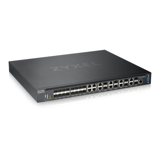
Ethernet ports support Multi-Gigabit (100 Mbps, 1 Gbps, 2.5 Gbps, 5 Gbps, and 10 Gbps). The figure below shows the front panel of the Switch. Figure 11 Front Panel: XS3800-28 The following table describes the ports. Table 4 Panel Connections... -
Page 42: Ethernet Ports
You can change transceivers or the DAC cables while the Switch is operating. You can use different transceivers to connect to Ethernet switches with different types of fiber connectors. • Type: SFP connection interface • Connection speed: 1 or 10 Gigabit per second (Gbps) XS3800-28 User’s Guide... - Page 43 Remove the dust plugs from the transceiver and cables (dust plug styles vary). Identify the signal transmission direction of the fiber cables and the transceiver. Insert the fiber cable into the transceiver. Figure 12 Latch in the Lock Position Figure 13 Transceiver Installation Example XS3800-28 User’s Guide...
- Page 44 Switch and transceiver. Insert the dust plug into the ports on the transceiver and the cables. Figure 15 Removing the Fiber Cables Figure 16 Opening the Transceiver’s Latch Example Figure 17 Transceiver Removal Example XS3800-28 User’s Guide...
-
Page 45: Dual Personality Interfaces
• No parity, 8 data bits, 1 stop bit • No flow control 3.2 Rear Panel The following figures show the rear panels of the Switch. The rear panels contain: • Two AC power receptacles (A and B) Figure 19 Rear Panel: XS3800-28 XS3800-28 User’s Guide... -
Page 46: Grounding
Attach the other end of the ground cable to a grounding bar located on the rack where you install the Switch or to an on-site grounding terminal. Figure 21 Attach Ground Cable to Grounding Bar or On-site Grounding Terminal XS3800-28 User’s Guide... -
Page 47: Ac Power Connection
Use the following procedures to connect the Switch to a power source after you have installed it in a rack. Note: Use the included power cord for the AC power connection. Connect the female end of the power cord to the AC power socket. Connect the other end of the cord to a power outlet. XS3800-28 User’s Guide... -
Page 48: Leds
SYS (System) Green The Switch is on and functioning properly. Blinking The Switch is rebooting and performing self-diagnostic tests. The Switch is functioning abnormally. The power is off or the system is not ready or malfunctioning. XS3800-28 User’s Guide... - Page 49 Mbps through the MGMT port. The MGMT port is not connected to an Ethernet device, or the port is disabled. STACK ID The LED is showing the Stack ID number of the Switch. ID 0 means it is a standalone Switch. XS3800-28 User’s Guide...
-
Page 50: Technical Reference
Technical Reference... -
Page 51: Web Configurator
Also, you can use the ZON Utility to check your Switch’s IP address. See Section 4.3 on page 55 for more information on the ZON utility. The following screen appears. XS3800-28 User’s Guide... - Page 52 Select the Web Configurator in Standard Mode that has a complete set of configuration for network installation. Or select the Web Configurator in Networked AV Mode that has a set of menus specifically designed to simplify configuration and management of the Switch for AVoIP (Audio-Video over Internet XS3800-28 User’s Guide...
- Page 53 If you log into the Web Configurator and select Networked AV Mode, open the screen in the Wizard > Step 2 Password to change the administrator password and SNMP community string. Click Finish on the last step of the Wizard to save your settings. XS3800-28 User’s Guide...
- Page 54 Get Community Enter the Get Community string, which is the password for the incoming Get- and GetNext- requests from the management station. The Get Community string is only used by SNMP managers using SNMP version 2c or lower. XS3800-28 User’s Guide...
-
Page 55: Zyxel One Network (Zon) Utility
Note: To check for your Windows operating system version, right-click on My Computer > Properties. You should see this information in the General tab. Hardware Here are the minimum hardware requirements to use the ZON Utility on your computer. • Core i3 processor XS3800-28 User’s Guide... -
Page 56: Run The Zon Utility
ZON icon in the upper right of the screen. Then select the Supported model and firmware version link. If your device is not listed here, see the device release notes for ZON Utility support. The release notes are in the firmware zip file on the Zyxel web site. XS3800-28 User’s Guide... - Page 57 Select a network adapter to which your supported devices are connected. Figure 30 Network Adapter Click the Go button for the ZON Utility to discover all supported devices in your network. Figure 31 Discovery The ZON Utility screen shows the devices discovered. XS3800-28 User’s Guide...
- Page 58 7 Firmware Upgrade Use this icon to upgrade new firmware to selected devices of the same model. Make sure you have downloaded the firmware from the Zyxel website to your computer and unzipped it in advance. XS3800-28 User’s Guide...
-
Page 59: Networked Av Mode Wizard
The Setup Wizard can be accessed using the following methods: • When the Switch is in its factory-default state, selecting Networked AV mode will automatically access the Setup Wizard. • When in Networked AV mode, click the Wizard link to access the Setup Wizard. XS3800-28 User’s Guide... -
Page 60: Basic Settings
Networked AV mode settings, and view finished results. In order to set up your IP or DNS, please do the following. Click Wizard > Basic Settings > Step 1 IP to access this screen. Figure 35 Wizard > Basic Settings > Step 1 IP XS3800-28 User’s Guide... - Page 61 IP address. Next Click Next to show the next screen. Cancel Click Cancel to exit this screen without saving. After clicking Next, the Password screen appears. Figure 36 Wizard > Basic Settings > Step 2 Password XS3800-28 User’s Guide...
- Page 62 The Trap Community string is only used by SNMP managers using SNMP version 2c or lower. Previous Click Previous to show the previous screen. Next Click Next to show the next screen. Cancel Click Cancel to exit this screen without saving. After clicking Next, the Networked AV screen appears. XS3800-28 User’s Guide...
- Page 63 (for example computer, NAS) to the RJ45 ports. Previous Click Previous to show the previous screen. Next Click Next to show the next screen. Cancel Click Cancel to exit this screen without saving. After clicking Next, the Summary screen appears. XS3800-28 User’s Guide...
- Page 64 This field displays the Get Community string. Set Community This field displays the Set Community string. Trap Community This field displays the Trap Community string. Networked AV – Basic Settings Networked AV VLAN This field displays the VLAN ID for the AVoIP network. XS3800-28 User’s Guide...
-
Page 65: Advanced Settings
Networked AV service to a VLAN, select and assign port role, link aggregation (trunking), and view finished results. In order to set up your IP or DNS, please do the following. Click Wizard > Advanced Settings > Step 1 IP to access this screen. XS3800-28 User’s Guide... - Page 66 Enter a domain name server IP address in order to be able to use a domain name instead of an IP address. Next Click Next to show the next screen. Cancel Click Cancel to exit this screen without saving. After clicking Next, the Password screen appears. XS3800-28 User’s Guide...
- Page 67 The Get Community string is only used by SNMP managers using SNMP version 2c or lower. Set Community Enter the Set Community string, which is the password for the incoming Set- requests from the management station. The Set Community string is only used by SNMP managers using SNMP version 2c or lower. XS3800-28 User’s Guide...
- Page 68 You must enter a different VLAN ID in the Networked AV VLAN field to be able to assign another subnet mask that specifies the network number portion of an IP address. (Optional) Select Ports and Assign a Port Role XS3800-28 User’s Guide...
- Page 69 Figure 42 Wizard > Advanced Settings > Step 4 Summary Each field is described in the following table. Table 16 Wizard > Advanced Settings > Step 4 Summary LABEL DESCRIPTION Setup IP Host Name This field displays a host name. XS3800-28 User’s Guide...
-
Page 70: Web Configurator Layout
Click Cancel to exit this screen without saving. 4.5 Web Configurator Layout The Status screen is the first screen that displays when you access the Web Configurator. The following figure shows the navigating components of a Web Configurator screen. XS3800-28 User’s Guide... - Page 71 – Click this link to go to the NCC (Nebula Control Center) portal website. – Click this link to go to the Neighbor screen where you can see and manage neighbor devices – learned by the Switch. XS3800-28 User’s Guide...
- Page 72 MAC address learning, GARP and priority queues. IP Setup This link takes you to a screen where you can configure the IP address, subnet mask (necessary for Switch management) and set up to 128 IP routing domains. XS3800-28 User’s Guide...
- Page 73 VLAN Stacking This link takes you to screens where you can activate and configure VLAN stacking. Multicast This link takes you to screen where you can configure various multicast features, IGMP snooping, MLD snooping-proxy and create multicast VLANs. XS3800-28 User’s Guide...
- Page 74 IPv4 RIP timer, and the method of preventing routing loops. OSPF This link takes you to a screen where you can view the OSPF status and configure OSPF settings for IPv4. IGMP This link takes you to a screen where you can configure the IGMP settings. XS3800-28 User’s Guide...
- Page 75 This link takes you to a screen where you can view the port statistics. Service Register This link takes you to a screen where you can view the status of your service registrations and upgrade licenses. Table 19 Navigation Panel Sub-links Overview (Networked AV Mode) SUMMARY SYSTEM PORT SWITCHING XS3800-28 User’s Guide...
- Page 76 SNMP traps that should be sent to each SNMP manager, and add/edit user information. Service This link takes you to a screen where you can decide what services you may use to access the Access Switch. Control XS3800-28 User’s Guide...
-
Page 77: Change Your Password
Settings in the run-time memory are lost when the Switch’s power is turned off. Click the Save link in the upper right of the Web Configurator to save your configuration to non-volatile memory. Non-volatile memory refers to the Switch’s storage that remains even if the Switch’s power is turned off. XS3800-28 User’s Guide... -
Page 78: Switch Lockout
115200 bps with 8 data bit, no parity, one stop bit and flow control set to none. The password will also be reset to “1234” and the IP address to 192.168.1.1 or DHCP- assigned IP. To upload the configuration file, do the following: XS3800-28 User’s Guide... -
Page 79: Log Out Of The Web Configurator
Click Logout in a screen to exit the Web Configurator. You have to log in with your password again after you log out. This is recommended after you finish a management session for security reasons. Figure 46 Web Configurator: Logout Screen XS3800-28 User’s Guide... -
Page 80: Help
Chapter 4 Web Configurator 4.10 Help The Web Configurator’s online help has descriptions of individual screens and some supplementary information. Click the Help link from a Web Configurator screen to view an online help description of that screen. XS3800-28 User’s Guide... -
Page 81: Initial Setup Example
In this example, you want to configure port 1 as a member of VLAN 2. Figure 47 Initial Setup Network Example: VLAN Click Advanced Application > VLAN > VLAN Configuration in the navigation panel and click the Static VLAN Setup link. XS3800-28 User’s Guide... -
Page 82: Set Port Vid
Use PVID to add a tag to incoming untagged frames received on that port so that the frames are forwarded to the VLAN group that the tag defines. In the example network, configure 2 as the port VID on port 1 so that any untagged frames received on that port get sent to VLAN 2. XS3800-28 User’s Guide... -
Page 83: Configure Switch Management Ip Address
If the Switch fails to obtain an IP address from a DHCP server, the Switch will use 192.168.1.1 as the management IP address. You can configure another IP address in a different subnet for management purposes. The following figure shows an example. XS3800-28 User’s Guide... - Page 84 Open your web browser and enter 192.168.1.1 (the default IP address) in the address bar to access the Web Configurator. See Section 4.2 on page 51 for more information. Click Basic Setting > IP Setup > IP Configuration in the navigation panel. XS3800-28 User’s Guide...
- Page 85 This is the same as the VLAN ID you configure in the Static VLAN screen. Click Add to save your changes back to the run-time memory. Settings in the run-time memory are lost when the Switch’s power is turned off. XS3800-28 User’s Guide...
-
Page 86: Tutorials
Access the Switch through http://192.168.1.1 by default. Log into the Switch by entering the user name (default: admin) and password (default: 1234). Go to Advanced Application > VLAN > VLAN Configuration > Static VLAN Setup, and create a VLAN with XS3800-28 User’s Guide... - Page 87 Go to Advanced Application > VLAN > VLAN Configuration > VLAN Port Setup, and set the PVID of the ports 5, 6 and 7 to 100. This tags untagged incoming frames on ports 5, 6 and 7 with the tag 100. Click Apply. Figure 52 Tutorial: Tag Untagged Frames XS3800-28 User’s Guide...
- Page 88 The DHCP Snooping Port Configure screen appears. Select Trusted in the Server Trusted state field for port 5 because the DHCP server is connected to port 5. Keep ports 6 and 7 Untrusted because they are connected to DHCP clients. Click Apply. XS3800-28 User’s Guide...
- Page 89 Then select Yes in the Enabled field of the VLAN 100 entry shown at the bottom section of the screen. Click Apply. If you want to add more information in the DHCP request packets such as source VLAN ID or system name, you can also select an Option82 Profile in the entry. XS3800-28 User’s Guide...
-
Page 90: How To Use Dhcpv4 Relay On The Switch
In this example, you have configured your DHCP server (192.168.2.3) and want to have it assign a specific IP address (say 172.16.1.18) to DHCP client A based on the system name, VLAN ID and port number in the DHCP request. Client A connects to the Switch’s port 2 in VLAN 102. XS3800-28 User’s Guide... -
Page 91: Create A Vlan
102 in the VLAN Group ID field. Select Fixed to configure port 2 to be a permanent member of this VLAN. Clear the TX Tagging check box to set the Switch to remove VLAN tags before sending. XS3800-28 User’s Guide... - Page 92 Enter 102 in the PVID field for port 2 to add a tag to incoming untagged frames received on that port so that the frames are forwarded to the VLAN group that the tag defines. 10 Click Apply to save your changes back to the run-time memory. XS3800-28 User’s Guide...
-
Page 93: Configure Dhcpv4 Relay
Figure 62 Tutorial: Set DHCP Server and Relay Information Click the Save link in the upper right of the Web Configurator to save your configuration permanently. The DHCP server can then assign a specific IP address based on the DHCP request. XS3800-28 User’s Guide... -
Page 94: Troubleshooting
Switch load this auto configuration file, two conditions listed above must be met. Please refer to the following steps to see how to set up a Vendor Class Identifier on the Switch. Setting up a TFTP Server Select a directory on the TFTP server. Put the configuration files in that directory. XS3800-28 User’s Guide... - Page 95 Identifier assigned when you reboot the Switch, follow the instruction below. Otherwise, skip this step. In the Basic Setting > IP Setup > IP Configuration screen, select the check box in the Option-60 field, and enter a Vendor Class Identifier in the Class-ID field. In this example, we use “ZyxelCorp”. Click Add. XS3800-28 User’s Guide...
- Page 96 Click the same button next to Reboot System field to reboot the Switch, and load the auto configuration setting as configured before. For example, if you save the auto configuration setting to Config 1, you need to click the Config 1 button next to the Reboot System field. XS3800-28 User’s Guide...
- Page 97 Check the screens to see if it is the configuration file you want to load. If it is not, go through the steps above to check your configurations. If it is, click Save at the top right corner of the Web Configurator to save the configuration permanently. Figure 68 Tutorial: Save XS3800-28 User’s Guide...
-
Page 98: Status
Switch’s neighbor devices. 7.2 Status The Status screen displays when you log into the Switch or click Status at the top right of the Web Configurator. The Status screen displays general device information, system status, and its IP addresses. XS3800-28 User’s Guide... - Page 99 Timeout(mins) times out. After it times out you have to log in with your password again. Serial Number This field displays the serial number of this Switch. The serial number is used for device tracking and control. XS3800-28 User’s Guide...
-
Page 100: Neighbor Screen
This screen shows the neighboring device first recognized on an Ethernet port of the Switch. Device information is displayed in gray when the neighboring device is offline. Click Status > Neighbor to see the following screen. XS3800-28 User’s Guide... -
Page 101: Neighbor Detail
Flush Click the Flush button to remove information about neighbors learned on the selected ports. 7.2.2 Neighbor Detail Use this screen to view detailed information about the neighboring devices. Device information is XS3800-28 User’s Guide... - Page 102 Remote System Name This shows the system name of the neighbor device. Model This shows the model name of the neighbor device. This field will show “–” for devices that do not support the ZON utility. XS3800-28 User’s Guide...
- Page 103 This shows the description of the neighbor device’s port which is connected to the Switch. Location This shows the geographic location of the neighbor device. This field will show “–” for devices that do not support the ZON utility. XS3800-28 User’s Guide...
-
Page 104: Basic Setting
142) to display links to Nebula Control Center Discovery and Nebula Switch Registration screens. 8.2 System Information In the navigation panel, click Basic Setting > System Info to display the screen as shown. Use this screen to view general system information. XS3800-28 User’s Guide... - Page 105 Chapter 8 Basic Setting Figure 72 Basic Setting > System Info (Standalone Mode) XS3800-28 User’s Guide...
- Page 106 This field displays the maximum temperature measured at this sensor. This field displays the minimum temperature measured at this sensor. Threshold This field displays the upper temperature limit at this sensor. Status This field displays Normal for temperatures below the threshold and Error for those above. XS3800-28 User’s Guide...
-
Page 107: System Information Stacking Hardware Monitor
This shows if the Switch is properly operating from the connected power source. 8.2.1 System Information Stacking Hardware Monitor Click a slot number in the System Information screen to display more detailed hardware information on a Switch. XS3800-28 User’s Guide... - Page 108 This field displays this fan's maximum speed measured in RPM. This field displays this fan's minimum speed measured in RPM. “<41" is displayed for speeds too small to measure (under 2000 RPM). Threshold This field displays the minimum speed at which a normal fan should work. XS3800-28 User’s Guide...
-
Page 109: General Setup
Use this screen to configure general settings such as the system name and time. Click Basic Setting > General Setup in the navigation panel to display the screen as shown. Figure 75 Basic Setting > General Setup XS3800-28 User’s Guide... - Page 110 UTC). So in the European Union you would select Last, Sunday, March and the last field depends on your time zone. In Germany for instance, you would select 2:00 because Germany's time zone is one hour ahead of GMT or UTC (GMT+1). XS3800-28 User’s Guide...
-
Page 111: Introduction To Vlans
Click Basic Setting > Switch Setup in the navigation panel to display the screen as shown. The VLAN setup screens change depending on whether you choose 802.1Q or Port Based in the VLAN Type field in this screen (in Standalone mode). XS3800-28 User’s Guide... - Page 112 MAC address learning reduces outgoing traffic broadcasts. For MAC address learning to occur on a port, the port must be active. Aging Time Enter a time from 10 to 1000000 seconds. This is how long all dynamically learned MAC addresses remain in the MAC address table before they age out (and must be relearned). XS3800-28 User’s Guide...
-
Page 113: Ip Setup
Cancel Click Cancel to begin configuring this screen afresh. 8.6 IP Setup Use the IP Setup screen to configure the default gateway device, the default domain name server and add IP domains. XS3800-28 User’s Guide... -
Page 114: Ip Interfaces
This field displays the VLAN identification number of the IP domain on the Switch. Type This shows whether this IP address is dynamically assigned from a DHCP server or manually assigned (Static). Renew Click this to renew the dynamic IP address. Release Click this to release the dynamic IP address. XS3800-28 User’s Guide... -
Page 115: Ip Status Details
This displays the length of time from the lease start that the Switch will request to renew its current dynamic IP address from the DHCP server. Rebind Time This displays the length of time from the lease start that the Switch will request to get any dynamic IP address from the DHCP server. XS3800-28 User’s Guide... -
Page 116: Ip Configuration
0.0.0.0 means no DNS server is assigned. 8.6.4 IP Configuration Use this screen to configure the default gateway device, the default domain name server and add IP domains. Figure 81 Basic Setting > IP Setup > IP Configuration XS3800-28 User’s Guide... - Page 117 IP address of the Switch in an IP routing domain. IP Subnet Enter the IP subnet mask of an IP routing domain in dotted decimal notation, for example, Mask 255.255.255.0. Enter the VLAN identification number to which an IP routing domain belongs. XS3800-28 User’s Guide...
-
Page 118: Network Proxy Configuration
Switch and NCC through the proxy server. Figure 82 Network Proxy Configuration Application As of this writing, this setting only allows communication between the Switch and the NCC. Figure 83 Basic Setting > IP Setup > IP Configuration > Network Proxy Configuration XS3800-28 User’s Guide... -
Page 119: Port Setup
Click Cancel to reset the fields to your previous configuration. 8.7 Port Setup Use this screen to configure Switch port settings. Click Basic Setting > Port Setup in the navigation panel to display the configuration screen. Figure 84 Basic Setting > Port Setup (Standalone Mode) XS3800-28 User’s Guide... - Page 120 When the Switch’s auto-negotiation is turned off, a port uses the pre-configured speed and duplex mode when making a connection, thus requiring you to make sure that the settings of the peer port are the same in order to connect. XS3800-28 User’s Guide...
-
Page 121: Interface Setup
Use this screen to set IPv4 loopback interfaces for routing protocols or IPv6 interfaces on which you can configure an IPv6 address to access and manage the Switch. Click Basic Setting > Interface Setup in the navigation panel to display the configuration screen. XS3800-28 User’s Guide... -
Page 122: Ipv6
Use this screen to view the IPv6 interface status and configure the Switch’s management IPv6 addresses. 8.9.1 IPv6 Status Click Basic Setting > IPv6 in the navigation panel to display the IPv6 status screen as shown next. XS3800-28 User’s Guide... -
Page 123: Ipv6 Interface Status
This field displays whether the IPv6 interface is activated or not. 8.9.2 IPv6 Interface Status Use this screen to view a specific IPv6 interface status and detailed information. Click an interface index number in the Basic Setting > IPv6 screen. The following screen opens. XS3800-28 User’s Guide... - Page 124 IP address is preferred, which means it is a valid address and can be used as a sender or receiver address. Global Unicast This field displays the Switch’s global unicast address to identify this interface. Address(es) Joined Group This field displays the IPv6 multicast addresses of groups the Switch’s interface joins. Address(es) XS3800-28 User’s Guide...
-
Page 125: Ipv6 Configuration
DHCPv6 Client and DNS information for this interface. 8.9.3 IPv6 Configuration Use this screen to configure IPv6 settings on the Switch. Click the IPv6 Configuration link in the Basic Setting > IPv6 screen. The following screen opens. XS3800-28 User’s Guide... -
Page 126: Ipv6 Global Setup
Use this screen to configure the global IPv6 settings. Click the link next to IPv6 Global Setup in the IPv6 Configuration screen to display the screen as shown next. Figure 90 Basic Setting > IPv6 > IPv6 Configuration > IPv6 Global Setup XS3800-28 User’s Guide... -
Page 127: Ipv6 Interface Setup
This is the interface index number. Click on an index number to change the settings. Interface This is the name of the IPv6 interface you created. Active This field displays whether the IPv6 interface is activated or not. XS3800-28 User’s Guide... -
Page 128: Ipv6 Link-Local Address Setup
Gateway 8.9.7 IPv6 Global Address Setup Use this screen to configure the interface’s IPv6 global address. Click the link next to IPv6 Global Address Setup in the IPv6 Configuration screen to display the screen as shown next. XS3800-28 User’s Guide... - Page 129 This shows whether the interface ID of the global address is generated using the EUI-64 format. Select an entry’s check box to select a specific entry. Otherwise, select the check box in the table heading row to select all entries. XS3800-28 User’s Guide...
-
Page 130: Ipv6 Neighbor Discovery Setup
This is the interface index number. Click on an index number to change the settings. Interface This is the name of the IPv6 interface you created. DAD Attempts This field displays the number of consecutive neighbor solicitations the Switch sends for this interface. XS3800-28 User’s Guide... -
Page 131: Ipv6 Router Discovery Setup
Note: The minimum time interval cannot be greater than three-quarters of the maximum time interval. Maximum Interval Specify the maximum time interval (from 4 to 1800 seconds) at which the Switch sends router advertisements for this interface. XS3800-28 User’s Guide... -
Page 132: Ipv6 Prefix Setup
Use this screen to configure the Switch’s IPv6 prefix list for each interface. Click the link next to IPv6 Prefix Setup in the IPv6 Configuration screen to display the screen as shown next. Figure 96 Basic Setting > IPv6 > IPv6 Configuration > IPv6 Prefix Setup XS3800-28 User’s Guide... -
Page 133: Ipv6 Neighbor Setup
Use this screen to create a static IPv6 neighbor entry in the Switch’s IPv6 neighbor table to store the neighbor information permanently. Click the link next to IPv6 Neighbor Setup in the IPv6 Configuration screen to display the screen as shown next. XS3800-28 User’s Guide... - Page 134 Select an entry’s check box to select a specific entry. Otherwise, select the check box in the table heading row to select all entries. Delete Check the entries that you want to remove and then click Delete to remove the selected entries from the summary table. Cancel Click Cancel to clear the check boxes. XS3800-28 User’s Guide...
-
Page 135: Dhcpv6 Client Setup
This field displays whether the Switch obtains a list of domain names from the DHCP server. Information This field displays the time interval (in seconds) at which the Switch exchanges other configuration Refresh information with a DHCPv6 server again. Minimum XS3800-28 User’s Guide... -
Page 136: Loopback Interface
Enter the IP address of your Switch in dotted decimal notation, for example, 192.168.1.1. This is the IP address of the Switch in an IP routing domain. IP Subnet Mask Enter the IP subnet mask of an IP routing domain in dotted decimal notation, for example, 255.255.255.0. XS3800-28 User’s Guide... -
Page 137: Stacking
25 and 26 (channel 1) on Switch A can connect to ports 25 and 26 (channel 1) or ports 27 and 28 (channel 2) on Switch B. Table 49 Stacking Channels and Ports STACKING CHANNEL STACKING PORTS 25, 26 27, 28 XS3800-28 User’s Guide... -
Page 138: Stacking Status
‘Slot’ refers to a Switch in the ‘virtual chassis’ stack. This field displays the slot ID of the stacked Switch. You can click the ID number to go to the Stacking Slot Status screen. Name This field displays the model name of the stacked Switch XS3800-28 User’s Guide... -
Page 139: Stacking Slot
This field displays the slot ID of the Switch. Stacking This field displays whether the Switch is active in the stacking system. Role This field displays whether the stacked Switch is a master, backup or linecard Switch XS3800-28 User’s Guide... -
Page 140: Stacking Configuration
Switch with the longest up-time is selected. Uptime is measured in increments of 10 minutes. The Switch with the higher number of increments is selected. If they have the same uptime, then the Switch with the lowest MAC address will be the master. XS3800-28 User’s Guide... - Page 141 Repeat steps 4 to 6 to connect other Switches to the stack. When the Switch is in Stacking mode, the Web Configurator will change port and VLAN port settings to support the stacking mode. Click Basic Setting > Stacking > Configuration to see the following screen. XS3800-28 User’s Guide...
-
Page 142: Cloud Management
Click Apply to save the Slot ID After Reboot field. Cancel Click Cancel to clear the Slot ID After Reboot field. 8.12 Cloud Management The Zyxel Nebula Control Center (NCC) is a cloud-based network management system that allows you XS3800-28 User’s Guide... -
Page 143: Nebula Center Control Discovery
Upgrade the firmware and reboot. Note: While the Switch is rebooting, do NOT turn off the power. Clear Active to turn off NCC discovery on the Switch. The Switch will NOT discover the NCC and remain in standalone mode. XS3800-28 User’s Guide... -
Page 144: Nebula Switch Registration
This screen has a QR code containing the Switch’s serial number and MAC address for handy NCC registration of the Switch using the Nebula Mobile app. First, download the app from the Google Play store for Android devices or the App Store for iOS devices and create an organization and site. XS3800-28 User’s Guide... -
Page 145: Vlan
You can specify a mask for the MAC address to create a MAC address filter and enter a weight to set the VLAN rule’s priority. 9.1.2 What You Need to Know Read this section to know more about VLAN and how to configure the screens. XS3800-28 User’s Guide... -
Page 146: Introduction To Ieee 802.1Q Tagged Vlans
Switches join VLANs by making a declaration. A declaration is made by issuing a Join message using GARP. Declarations are withdrawn by issuing a Leave message. A Leave All message terminates all registrations. GARP timers set declaration timeout values. XS3800-28 User’s Guide... - Page 147 (A and B). C, D and E automatically allow frames with VLAN group tags 1 and 2 (VLAN groups that are unknown to those switches) to pass through their VLAN trunking ports. Figure 109 Port VLAN Trunking XS3800-28 User’s Guide...
-
Page 148: Vlan Status
You can also tag all outgoing frames (that were previously untagged) from a port with the specified VID. 9.3 VLAN Status Use this screen to view and search all static VLAN groups. Click Advanced Application > VLAN from the navigation panel to display the VLAN Status screen as shown next. XS3800-28 User’s Guide... -
Page 149: Vlan Details
Click Previous or Next to show the previous or next screen if all status information cannot be seen in one screen. 9.3.1 VLAN Details Use this screen to view detailed port settings and status of the static VLAN group. Click an index number in the VLAN Status screen to display VLAN details. XS3800-28 User’s Guide... - Page 150 This field shows the primary VLAN ID in the selected VLAN. VLAN Secondary This field shows the secondary VLAN ID in the selected VLAN. VLAN Type This field shows the type of private VLAN: Primary, Community or Isolated. XS3800-28 User’s Guide...
-
Page 151: Private Vlan Status
Use the Previous and Next buttons to display different pages. 9.5 VLAN Configuration Use this screen to view IEEE 802.1Q VLAN parameters for the Switch. Click Advanced Application > VLAN > VLAN Configuration to see the following screen. XS3800-28 User’s Guide... -
Page 152: Configure A Static Vlan
Click Click Here to configure the Vendor ID Based VLAN for the Switch. 9.6 Configure a Static VLAN Use this screen to configure a static VLAN for the Switch. Click the Static VLAN Setup link in the VLAN Configuration screen to display the screen as shown next. XS3800-28 User’s Guide... - Page 153 Chapter 9 VLAN Figure 116 Advanced Application > VLAN > VLAN Configuration > Static VLAN Setup (Standalone Mode) XS3800-28 User’s Guide...
- Page 154 51–53 includes 51, 52 and 53, but 51,53 does not include 52. Secondary private VLANs can only be associated with one primary private VLAN. SLOT This field appears only in stacking mode. Click the drop-down list to choose the slot number of the Switch in a stack. XS3800-28 User’s Guide...
-
Page 155: Configure Vlan Port Settings
Click Cancel to clear the check boxes. 9.7 Configure VLAN Port Settings Use this screen to configure the static VLAN (IEEE 802.1Q) settings on a port. Click the VLAN Port Setup link in the VLAN Configuration screen. XS3800-28 User’s Guide... - Page 156 Chapter 9 VLAN Figure 118 Advanced Application > VLAN > VLAN Configuration > VLAN Port Setup (Standalone Mode) Figure 119 Advanced Application > VLAN > VLAN Configuration > VLAN Port Setup (Stacking Mode) XS3800-28 User’s Guide...
-
Page 157: Subnet Based Vlans
Subnet based VLANs allow you to group traffic into logical VLANs based on the source IP subnet you specify. When a frame is received on a port, the Switch checks if a tag is added already and the IP XS3800-28 User’s Guide... - Page 158 VID of 300 for traffic received from IP subnet 10.1.1.0/24 (data services). All untagged incoming frames will be classified based on their source IP subnet and prioritized accordingly. That is video services receive the highest priority and data the lowest. Figure 120 Subnet Based VLAN Application Example XS3800-28 User’s Guide...
- Page 159 Index This is the index number identifying this subnet based VLAN. Click on any of these numbers to edit an existing subnet based VLAN. Active This field shows whether the subnet based VLAN is active or not. XS3800-28 User’s Guide...
-
Page 160: Protocol Based Vlans
C. Figure 122 Protocol Based VLAN Application Example 9.9.1 Configuring Protocol Based VLAN Click the Protocol Based VLAN Setup link in the VLAN Configuration screen to display the configuration screen as shown. XS3800-28 User’s Guide... - Page 161 Enter the ID of a VLAN to which the port belongs. This must be an existing VLAN which you defined in the Advanced Application > VLAN > Static VLAN screen. Priority Select the priority level that the Switch will assign to frames belonging to this VLAN. XS3800-28 User’s Guide...
- Page 162 Select the protocol. Leave the default value IP. Type the VLAN ID of an existing VLAN. In our example we already created a static VLAN with an ID of 5. Type 5. Leave the priority set to 0 and click Add. XS3800-28 User’s Guide...
-
Page 163: Voice Vlan
You can set priority level to the Voice VLAN and add MAC address of IP phones from specific manufacturers by using its ID from the Organizationally Unique Identifiers (OUI). Click the Voice VLAN Setup link in the VLAN Configuration screen to display the configuration screen as shown. XS3800-28 User’s Guide... - Page 164 Click Add to save your changes to the Switch’s run-time memory. The Switch loses these changes if it is turned off or loses power, so use the Save link on the top navigation panel to save your changes to the non-volatile memory when you are done configuring. XS3800-28 User’s Guide...
-
Page 165: Mac Based Vlan
Type a name up to 32 alpha numeric characters for the MAC-based VLAN entry. MAC Address Type a MAC address that is bind to the MAC-based VLAN entry. This is the source MAC address of the data packet that is looked up when untagged packets arrive at the Switch. XS3800-28 User’s Guide... -
Page 166: Vendor Id Based Vlan
As rules are processed one after the other, stating a priority order will let you choose which rule has to be applied first and which second. Click the Vendor ID Based VLAN Setup link in the VLAN Configuration screen to see the following screen. XS3800-28 User’s Guide... - Page 167 Select an entry’s check box to select a specific entry. Otherwise, select the check box in the table heading row to select all entries. Delete Click Delete to remove the selected entry from the summary table. Cancel Click Cancel to clear the check boxes. XS3800-28 User’s Guide...
-
Page 168: Port-Based Vlan Setup
If VLAN members need to communicate directly with each other, then select All Connected. Select Port Isolated if you want to restrict users from communicating directly. Click Apply to save your settings. The following screen shows users on a port-based, all-connected VLAN configuration. XS3800-28 User’s Guide... - Page 169 Chapter 9 VLAN Figure 129 Advanced Application > VLAN > Port Based VLAN Setup (All Connected) The following screen shows users on a port-based, port-isolated VLAN configuration. XS3800-28 User’s Guide...
- Page 170 CPU refers to the Switch management port. By default it forms a VLAN with all Ethernet ports. If it does not form a VLAN with a particular port then the Switch cannot be managed from that port. XS3800-28 User’s Guide...
- Page 171 Save link on the top navigation panel to save your changes to the non-volatile memory when you are done configuring. Cancel Click Cancel to begin configuring this screen afresh. XS3800-28 User’s Guide...
-
Page 172: Static Mac Forwarding
This may reduce the need for broadcasting. Click Advanced Application > Static MAC Forwarding in the navigation panel to display the configuration screen as shown. Figure 131 Advanced Application > Static MAC Forwarding (Standalone Mode) XS3800-28 User’s Guide... - Page 173 In stacking mode, the first number represents the slot ID and the second is the port number. Select an entry’s check box to select a specific entry. Otherwise, select the check box in the table heading row to select all entries. XS3800-28 User’s Guide...
- Page 174 Chapter 10 Static MAC Forwarding Table 66 Advanced Application > Static MAC Forwarding (continued) LABEL DESCRIPTION Delete Click Delete to remove the selected entry from the summary table. Cancel Click Cancel to clear the check boxes. XS3800-28 User’s Guide...
-
Page 175: Static Multicast Forwarding
Figure 134 on page shows frames being forwarded to devices connected to port 3. Figure 135 on page 176 shows frames being forwarded to ports 2 and 3 within VLAN group 4. Figure 133 No Static Multicast Forwarding XS3800-28 User’s Guide... -
Page 176: Configure Static Multicast Forwarding
Use this screen to configure rules to forward specific multicast frames, such as streaming or control frames, to specific ports. Click Advanced Application > Static Multicast Forwarding to display the configuration screen as shown. Figure 136 Advanced Application > Static Multicast Forwarding XS3800-28 User’s Guide... - Page 177 Select an entry’s check box to select a specific entry. Otherwise, select the check box in the table heading row to select all entries. Delete Click Delete to remove the selected entry from the summary table. Cancel Click Cancel to clear the check boxes. XS3800-28 User’s Guide...
-
Page 178: Filtering
12.2 Configure a Filtering Rule Use this screen to create rules for traffic going through the Switch. Click Advanced Application > Filtering in the navigation panel to display the screen as shown next. Figure 137 Advanced Application > Filtering XS3800-28 User’s Guide... - Page 179 Select an entry’s check box to select a specific entry. Otherwise, select the check box in the table heading row to select all entries. Delete Check the rules that you want to remove and then click the Delete button. Cancel Click Cancel to clear the selected check boxes. XS3800-28 User’s Guide...
-
Page 180: Spanning Tree Protocol
It allows a switch to interact with other (R)STP-compliant switches in your network to ensure that only one path exists between any two stations on the network. The Switch uses IEEE 802.1w RSTP (Rapid Spanning Tree Protocol) that allows faster convergence of the XS3800-28 User’s Guide... - Page 181 (Max Age), the bridge assumes that the link to the root bridge is down. This bridge then initiates negotiations with other bridges to reconfigure the network to re-establish a valid network topology. STP Port States STP assigns five port states to eliminate packet looping. A bridge port is not allowed to go directly from XS3800-28 User’s Guide...
- Page 182 • A VLAN can be mapped to a specific Multiple Spanning Tree Instance (MSTI). MSTI allows multiple VLANs to use the same spanning tree. • Load-balancing is possible as traffic from different VLANs can use distinct paths in a region. XS3800-28 User’s Guide...
-
Page 183: Spanning Tree Protocol Status
13.3 Spanning Tree Configuration Use the Spanning Tree Configuration screen to activate one of the STP modes on the Switch. Click Configuration in the Advanced Application > Spanning Tree Protocol. Figure 141 Advanced Application > Spanning Tree Protocol > Configuration XS3800-28 User’s Guide... -
Page 184: Rapid Spanning Tree Protocol Status
RSTP. Note: This screen is only available after you activate RSTP on the Switch. Figure 142 Advanced Application > Spanning Tree Protocol (Standalone Mode) Figure 143 Advanced Application > Spanning Tree Protocol (Stacking Mode) XS3800-28 User’s Guide... - Page 185 Otherwise, it displays the identifier of the designated bridge for the LAN segment to which this port is connected. Designated Port ID This field displays the priority and number of the bridge port (on the designated bridge), through which the designated bridge transmits the stored configuration messages. XS3800-28 User’s Guide...
-
Page 186: Configure Rapid Spanning Tree Protocol
Use this screen to configure RSTP settings, see Section 13.1 on page 180 for more information on RSTP. Click RSTP in the Advanced Application > Spanning Tree Protocol screen. Figure 144 Advanced Application > Spanning Tree Protocol > RSTP (Standalone Mode) XS3800-28 User’s Guide... - Page 187 LAN. If it is a root port, a new root port is selected from among the Switch ports attached to the network. The allowed range is 6 to 40 seconds. XS3800-28 User’s Guide...
-
Page 188: Configure Multiple Spanning Tree Protocol
Cancel Click Cancel to begin configuring this screen afresh. 13.6 Configure Multiple Spanning Tree Protocol To configure MSTP, click MSTP in the Advanced Application > Spanning Tree Protocol screen. XS3800-28 User’s Guide... - Page 189 Chapter 13 Spanning Tree Protocol Figure 146 Advanced Application > Spanning Tree Protocol > MSTP (Standalone Mode) XS3800-28 User’s Guide...
- Page 190 Spanning Tree Protocol > Configuration screen to enable MSTP on the Switch. Hello Time This is the time interval in seconds between BPDU (Bridge Protocol Data Units) configuration message generations by the root switch. The allowed range is 1 to 10 seconds. XS3800-28 User’s Guide...
- Page 191 Note: Changes in this row are copied to all the ports as soon as you make them. Active Select this check box to add this port to the MST instance. XS3800-28 User’s Guide...
-
Page 192: Multiple Spanning Tree Protocol Port Configuration
Click Cancel to clear the selected check boxes. 13.6.1 Multiple Spanning Tree Protocol Port Configuration Click Advanced Application > Spanning Tree Protocol > MSTP > Port in the navigation panel to display the status screen as shown next. XS3800-28 User’s Guide... - Page 193 Chapter 13 Spanning Tree Protocol Figure 148 Advanced Application > Spanning Tree Protocol > MSTP > Port (Standalone Mode) Figure 149 Advanced Application > Spanning Tree Protocol > MSTP > Port (Stacking Mode) XS3800-28 User’s Guide...
-
Page 194: Multiple Spanning Tree Protocol Status
13.7 Multiple Spanning Tree Protocol Status Click Advanced Application > Spanning Tree Protocol in the navigation panel to display the status screen as shown next. Note: This screen is only available after you activate MSTP on the Switch. XS3800-28 User’s Guide... - Page 195 Chapter 13 Spanning Tree Protocol Figure 150 Advanced Application > Spanning Tree Protocol (Standalone Mode) XS3800-28 User’s Guide...
- Page 196 This is the priority and number of the port on the Switch through which this Switch must communicate with the root of the Spanning Tree. Configuration This field displays the configuration name for this MST region. Name Revision Number This field displays the revision number for this MST region. XS3800-28 User’s Guide...
- Page 197 Otherwise, it displays the identifier of the designated bridge for the LAN segment to which this port is connected. Designated Port ID This field displays the priority and number of the bridge port (on the designated bridge), through which the designated bridge transmits the stored configuration messages. XS3800-28 User’s Guide...
-
Page 198: Configure Multiple Rapid Spanning Tree Protocol
Forwarding – the Switch unblocks and allows the port to forward frames again. 13.8 Configure Multiple Rapid Spanning Tree Protocol To configure MRSTP, click MRSTP in the Advanced Application > Spanning Tree Protocol screen. Figure 152 Advanced Application > Spanning Tree Protocol > MRSTP (Standalone Mode) XS3800-28 User’s Guide... - Page 199 LAN. If it is a root port, a new root port is selected from among the Switch ports attached to the network. The allowed range is 6 to 40 seconds. XS3800-28 User’s Guide...
-
Page 200: Multiple Rapid Spanning Tree Protocol Status
13.9 Multiple Rapid Spanning Tree Protocol Status Click Advanced Application > Spanning Tree Protocol in the navigation panel to display the status screen as shown next. See Section 13.9 on page 200 for more information on MRSTP. XS3800-28 User’s Guide... - Page 201 This is the time interval (in seconds) at which the root switch transmits a configuration (second) message. The root bridge determines Hello Time, Max Age and Forwarding Delay. Max Age (second) This is the maximum time (in seconds) the Switch can wait without receiving a configuration message before attempting to reconfigure. XS3800-28 User’s Guide...
- Page 202 This field displays the state of the port on which root guard is enabled. • Root – inconsistent – the Switch receives superior BPDUs on the port and blocks the port. • Forwarding – the Switch unblocks and allows the port to forward frames again. XS3800-28 User’s Guide...
-
Page 203: Technical Reference
Devices that belong to the same MST region are configured to have the same MSTP configuration identification settings. These include the following parameters: • Name of the MST region • Revision level as the unique number for the MST region XS3800-28 User’s Guide... -
Page 204: Mst Instance
CIST. In an MSTP-enabled network, there is only one CIST that runs between MST regions and single spanning tree devices. A network may contain multiple MST regions and other network segments running RSTP. XS3800-28 User’s Guide... - Page 205 Chapter 13 Spanning Tree Protocol Figure 159 MSTP and Legacy RSTP Network Example XS3800-28 User’s Guide...
-
Page 206: Bandwidth Control
Note: The sum of CIRs cannot be greater than or equal to the uplink bandwidth. 14.2 Bandwidth Control Setup Click Advanced Application > Bandwidth Control in the navigation panel to bring up the screen as shown next. XS3800-28 User’s Guide... - Page 207 This field displays the port number. In stacking mode, the first number represents the slot ID and the second is the port number. Please note that the default stacking ports (the last four ports of your Switch) cannot be configured. They are reserved for stacking only. XS3800-28 User’s Guide...
- Page 208 Save link on the top navigation panel to save your changes to the non-volatile memory when you are done configuring. Cancel Click Cancel to reset the fields. XS3800-28 User’s Guide...
-
Page 209: Broadcast Storm Control
(DLF) packets the Switch receives per second on the ports. 15.2 Broadcast Storm Control Setup Click Advanced Application > Broadcast Storm Control in the navigation panel to display the screen as shown next. XS3800-28 User’s Guide... - Page 210 Select this check box to enable traffic storm control on the Switch. Clear this check box to disable this feature. SLOT This field appears only in stacking mode. Click the drop-down list to choose the slot number of the Switch in a stack. XS3800-28 User’s Guide...
- Page 211 Save link on the top navigation panel to save your changes to the non-volatile memory when you are done configuring. Cancel Click Cancel to reset the fields. XS3800-28 User’s Guide...
-
Page 212: Mirroring
VLAN tagging and copied to the connected ports. Traffic are then carried over the specified remote port mirroring (RMirror) VLAN and sent to the destination device’s monitor port through the connected ports that connect to other switches. XS3800-28 User’s Guide... -
Page 213: Local Port Mirroring
16.2 Local Port Mirroring Click Advanced Application > Mirroring in the navigation panel to display the Mirroring screen. Use this screen to select a monitor port and specify the traffic flow to be copied to the monitor port. XS3800-28 User’s Guide... - Page 214 Chapter 16 Mirroring Figure 164 Advanced Application > Mirroring (Standalone Mode) XS3800-28 User’s Guide...
- Page 215 Save link on the top navigation panel to save your changes to the non-volatile memory when you are done configuring. Cancel Click Cancel to reset the fields. XS3800-28 User’s Guide...
-
Page 216: Remote Port Mirroring
Use this screen to configure the reflector port and specify the traffic flow to be copied to the monitor port when the Switch is the source device in remote port mirroring. Click the Source link in the RMirror screen. The following screen opens. XS3800-28 User’s Guide... - Page 217 Chapter 16 Mirroring Figure 167 Advanced Application > Mirroring > RMirror > Source (Standalone Mode) Figure 168 Advanced Application > Mirroring > RMirror > Source (Stacking Mode) XS3800-28 User’s Guide...
-
Page 218: Destination
16.2.3 Destination Use this screen to specify the RMirror VLAN and configure the monitor port when the Switch is the destination device in remote port mirroring. Click the Destination link in the RMirror screen. The following screen opens. XS3800-28 User’s Guide... - Page 219 Select an entry’s check box to select a specific entry. Otherwise, select the check box in the table heading row to select all entries. Delete Check the rules that you want to remove in the Delete column and then click the Delete button. Cancel Click Cancel to begin configuring this screen afresh. XS3800-28 User’s Guide...
-
Page 220: Connected Port
RMirror VLAN. Click the Connected Port link in the RMirror screen. The following screen opens. Figure 171 Advanced Application > Mirroring > RMirror > Connected Port (Standalone Mode) XS3800-28 User’s Guide... - Page 221 Save link on the top navigation panel to save your changes to the non-volatile memory when you are done configuring. Cancel Click Cancel to begin configuring this screen afresh. XS3800-28 User’s Guide...
- Page 222 DESCRIPTION VLAN This field displays the ID number of port mirroring VLAN over which the mirrored traffic is forwarded. Connected Port This field displays the number of ports that helps forward mirrored traffic to other connected switches. XS3800-28 User’s Guide...
-
Page 223: Link Aggregation
When you enable LACP link aggregation on a port, the port can automatically negotiate with the ports at the remote end of a link to establish trunk groups. LACP also allows port redundancy, that is, if an XS3800-28 User’s Guide... -
Page 224: Link Aggregation Status
Click Advanced Application > Link Aggregation in the navigation panel. The Link Aggregation Status screen displays by default. See Section 17.1 on page 223 for more information. Port Priority and Port Number are 0 as it is the aggregator ID for the trunk group, not the individual port. XS3800-28 User’s Guide... - Page 225 This field displays how these ports were added to the trunk group. It displays: • Static – if the ports are configured as static members of a trunk group. • LACP – if the ports are configured to join a trunk group through LACP. XS3800-28 User’s Guide...
-
Page 226: Link Aggregation Setting
Click Advanced Application > Link Aggregation > Link Aggregation Setting to display the screen shown next. See Section 17.1 on page 223 for more information on link aggregation. Figure 174 Advanced Application > Link Aggregation > Link Aggregation Setting (Standalone Mode) XS3800-28 User’s Guide... - Page 227 This is the only screen you need to configure to enable static link aggregation. Aggregation Setting Group ID The field identifies the link aggregation group, that is, one logical link containing multiple ports. Active Select this option to activate a trunk group. XS3800-28 User’s Guide...
-
Page 228: Link Aggregation Control Protocol
17.3.1 Link Aggregation Control Protocol Click Advanced Application > Link Aggregation > Link Aggregation Setting > LACP to display the screen shown next. See Dynamic Link Aggregation on page 223 for more information on dynamic link aggregation. XS3800-28 User’s Guide... - Page 229 Chapter 17 Link Aggregation Figure 176 Advanced Application > Link Aggregation > Link Aggregation Setting > LACP (Standalone Mode) XS3800-28 User’s Guide...
- Page 230 The field identifies the link aggregation group, that is, one logical link containing multiple ports. LACP Active Select this option to enable LACP for a trunk. SLOT This field appears only in stacking mode. Click the drop-down list to choose the slot number of the Switch in a stack. XS3800-28 User’s Guide...
-
Page 231: Technical Reference
T1, select the traffic distribution algorithm used by this group and select the ports that should belong to this group as shown in the figure below. Click Apply when you are done. XS3800-28 User’s Guide... - Page 232 Chapter 17 Link Aggregation Figure 179 Trunking Example – Configuration Screen EXAMPLE Your trunk group 1 (T1) configuration is now complete. XS3800-28 User’s Guide...
-
Page 233: Port Authentication
238) to activate MAC authentication. At the time of writing, IEEE 802.1x is not supported by all operating systems. See your operating system documentation. If your operating system does not support 802.1x, then you may need to install 802.1x client software. XS3800-28 User’s Guide... -
Page 234: What You Need To Know
Switch does not prompt the client for login credentials. The login credentials are based on the source MAC address of the client connecting to a port on the Switch along with a password configured specifically for MAC authentication on the Switch. XS3800-28 User’s Guide... -
Page 235: Port Authentication Configuration
Select a port authentication method’s link in the screen that appears. Figure 182 Advanced Application > Port Authentication 18.3 Activate IEEE 802.1x Security Use this screen to activate IEEE 802.1x security. In the Port Authentication screen click 802.1x to display the configuration screen as shown. XS3800-28 User’s Guide... - Page 236 Chapter 18 Port Authentication Figure 183 Advanced Application > Port Authentication > 802.1x (Standalone Mode) XS3800-28 User’s Guide...
- Page 237 Note: Changes in this row are copied to all the ports as soon as you make them. Active Select this to permit 802.1x authentication on this port. You must first allow 802.1x authentication on the Switch before configuring it on each port. XS3800-28 User’s Guide...
-
Page 238: Activate Mac Authentication
Cancel Click Cancel to begin configuring this screen afresh. 18.4 Activate MAC Authentication Use this screen to activate MAC authentication. In the Port Authentication screen click MAC Authentication to display the configuration screen as shown. XS3800-28 User’s Guide... - Page 239 Chapter 18 Port Authentication Figure 185 Advanced Application > Port Authentication > MAC Authentication (Standalone Mode) XS3800-28 User’s Guide...
- Page 240 Type the password the Switch sends along with the MAC address of a client for authentication with the RADIUS server. You can enter up to 32 printable ASCII characters except [ ? ], [ | ], [ ' ], [ " ] or [ , ]. XS3800-28 User’s Guide...
-
Page 241: Guest Vlan
That is, unauthenticated users can have access to limited network resources in the same guest VLAN, such as the Internet. The access granted to the Guest VLAN depends on how the network administrator configures switches or routers with the guest network feature. XS3800-28 User’s Guide... - Page 242 Use this screen to enable and assign a guest VLAN to a port. In the Port Authentication screen click Guest Vlan to display the configuration screen as shown. Figure 188 Advanced Application > Port Authentication > Guest VLAN (Standalone Mode) XS3800-28 User’s Guide...
- Page 243 Select Multi-Secure to authenticate each user that connects to this port. Multi-Secure Num If you set Host-mode to Multi-Secure, specify the maximum number of users (between 1 and 24) that the Switch will authenticate on this port. XS3800-28 User’s Guide...
-
Page 244: Compound Authentication
• In MAC authentication, the login credentials are based on the source MAC address of the client connecting to a port on the Switch along with a password configured specifically for MAC authentication on the Switch. In the Port Authentication screen click Compound Authentication Mode to display the configuration screen as shown. XS3800-28 User’s Guide... - Page 245 Chapter 18 Port Authentication Figure 190 Advanced Application > Port Authentication > Compound Authentication Mode (Standalone Mode) XS3800-28 User’s Guide...
- Page 246 Save link on the top navigation panel to save your changes to the non-volatile memory when you are done configuring. Cancel Click Cancel to begin configuring this screen afresh. XS3800-28 User’s Guide...
-
Page 247: Technical Reference
The following types of RADIUS messages are exchanged between the switch and the RADIUS server for user authentication: • Access-Request Sent by a switch requesting authentication. • Access-Reject Sent by a RADIUS server rejecting access. • Access-Accept Sent by a RADIUS server allowing access. XS3800-28 User’s Guide... -
Page 248: Eap (Extensible Authentication Protocol) Authentication
In addition, it is possible to impersonate an authentication server as MD5 authentication method does not perform mutual authentication. Finally, MD5 authentication method does not support data encryption with dynamic session key. You must configure WEP encryption keys for data encryption. • EAP-TLS (Transport Layer Security) XS3800-28 User’s Guide... -
Page 249: Eapol (Eap Over Lan)
• EAPOL-Logoff This message will be sent when the wired client wants to be disconnected from the network. • EAPOL-Encapsulated-ASF-Alert This message is sent If the authentication process is not completed yet, and alerts needs to be forwarded. XS3800-28 User’s Guide... -
Page 250: Port Security
By default, MAC address learning is still enabled even though the port security is not activated. 19.2 Port Security Setup Click Advanced Application > Port Security in the navigation panel to display the screen as shown. Figure 192 Advanced Application > Port Security (Standalone Mode) XS3800-28 User’s Guide... - Page 251 MAC addresses is in the MAC address table on this port. Packets with no matching MAC addresses are dropped. Clear this check box to disable the port security feature. The Switch forwards all packets on this port. XS3800-28 User’s Guide...
-
Page 252: Vlan Mac Address Limit
Address Limit in the Advanced Application > Port Security screen to display the screen as shown. Figure 194 Advanced Application > Port Security > VLAN MAC Address Limit (Standalone Mode) Figure 195 Advanced Application > Port Security > VLAN MAC Address Limit (Stacking Mode) XS3800-28 User’s Guide... - Page 253 Delete Check the rules that you want to remove in the Delete column and then click the Delete button. Cancel Click Cancel to clear the selected check boxes in the Delete column. XS3800-28 User’s Guide...
-
Page 254: Time Range
254) to view or define a schedule on the Switch. 20.2 Configuring Time Range Click Advanced Application > Time Range in the navigation panel to display the screen as shown. Figure 196 Advanced Application > Time Range XS3800-28 User’s Guide... - Page 255 Select an entry’s check box to select a specific entry. Otherwise, select the check box in the table heading row to select all entries. Delete Check the rules that you want to remove and then click the Delete button. Cancel Click Cancel to clear the selected check boxes. XS3800-28 User’s Guide...
-
Page 256: Classifier
Configure policy rules to define actions to be performed on a classified traffic flow (refer to Chapter 22 on page 265 to configure policy rules). You can also configure policy routing to forward a classified traffic flow to a different gateway for cost savings and load sharing. XS3800-28 User’s Guide... -
Page 257: Classifier Status
Use the Classifier Configuration screen to define the classifiers. After you define the classifier, you can specify actions (or policy) to act upon the traffic that matches the rules. In the Classifier Status screen click Classifier Configuration to display the configuration screen as shown. XS3800-28 User’s Guide... - Page 258 Chapter 21 Classifier Figure 198 Advanced Application > Classifier > Classifier Configuration XS3800-28 User’s Guide...
- Page 259 For example, if you set the MAC address to 00:13:49:00:00:00 and the mask to ff:ff:ff:00:00:00, a packet with a MAC address of 00:13:49:12:34:56 matches this criteria. If you leave the Mask field blank, the Switch automatically sets the mask to ff:ff:ff:ff:ff:ff. XS3800-28 User’s Guide...
- Page 260 Note: You must select either UDP or TCP in the IP Protocol field before you configure the Number socket numbers. Select Any to apply the rule to all TCP/UDP protocol port numbers or select the second option and enter a TCP/UDP protocol port number. XS3800-28 User’s Guide...
-
Page 261: Viewing And Editing Classifier Configuration Summary
Select an entry’s check box to select a specific entry. Otherwise, select the check box in the table heading row to select all entries. Delete Click Delete to remove the selected entry from the summary table. Cancel Click Cancel to clear the check boxes. XS3800-28 User’s Guide... -
Page 262: Classifier Global Setting Configuration
Use this screen to configure the match order and enable logging on the Switch. In the Classifier Configuration screen click Classifier Global Setting to display the configuration screen as shown. Figure 200 Advanced Application > Classifier > Classifier Configuration > Classifier Global Setting XS3800-28 User’s Guide... -
Page 263: Classifier Example
Cancel Click Cancel to begin configuring this screen afresh. 21.5 Classifier Example The following screen shows an example where you configure a classifier that identifies all traffic from MAC address 00:50:ba:ad:4f:81 on port 2. XS3800-28 User’s Guide... - Page 264 Figure 201 Classifier: Example EXAMPLE After you have configured a classifier, you can configure a policy (in the Policy screen) to define actions on the classified traffic flow. XS3800-28 User’s Guide...
-
Page 265: Policy Rule
The DSCP value determines the forwarding behavior, the PHB (Per-Hop Behavior), that each packet gets across the DiffServ network. Based on the marking rule, different kinds of traffic can be marked for different kinds of forwarding. Resources can then be allocated according to the DSCP values and the configured policies. XS3800-28 User’s Guide... -
Page 266: Configuring Policy Rules
Figure 202 Advanced Application > Policy Rule The following table describes the labels in this screen. Table 104 Advanced Application > Policy Rule LABEL DESCRIPTION Active Select this option to enable the policy. Name Enter a descriptive name for identification purposes. XS3800-28 User’s Guide... - Page 267 Select Send the packet to the egress port to send the packet to the egress port. Metering Select Enable to activate bandwidth limitation on the traffic flows then set the actions to be taken on out-of-profile packets. XS3800-28 User’s Guide...
-
Page 268: Policy Example
22.3 Policy Example The figure below shows an example Policy screen where you configure a policy to limit bandwidth and discard out-of-profile traffic on a traffic flow classified using the Example classifier (refer to Section 21.5 on page 263). XS3800-28 User’s Guide... - Page 269 Chapter 22 Policy Rule Figure 203 Policy Example EXAMPLE XS3800-28 User’s Guide...
-
Page 270: Queuing Method
This queue then moves to the back of the list. The next queue is given an equal amount of bandwidth, and then moves to the end of the list; and so on, depending on the number of queues being used. This works in a looping fashion until a queue is empty. XS3800-28 User’s Guide... -
Page 271: Configuring Queuing
Use this screen to set priorities for the queues of the Switch. This distributes bandwidth across the different traffic queues. Click Advanced Application > Queuing Method in the navigation panel. Figure 204 Advanced Application > Queuing Method (Standalone Mode) XS3800-28 User’s Guide... - Page 272 Use this row only if you want to make some settings the same for all ports. Use this row first to set the common settings and then make adjustments on a port-by-port basis. Note: Changes in this row are copied to all the ports as soon as you make them. XS3800-28 User’s Guide...
- Page 273 Save link on the top navigation panel to save your changes to the non-volatile memory when you are done configuring. Cancel Click Cancel to begin configuring this screen afresh. XS3800-28 User’s Guide...
-
Page 274: Vlan Stacking
VLAN group. The service provider can separate these two VLANs within its network by adding tag 37 to distinguish customer A and tag 48 to distinguish customer B at edge device 1 and then stripping those tags at edge device 2 as the data frames leave the network. XS3800-28 User’s Guide... -
Page 275: Vlan Stacking Port Roles
Note: Static VLAN Tx Tagging MUST be enabled on a port where you choose Tunnel Port. 24.3 VLAN Tag Format A VLAN tag (service provider VLAN stacking or customer IEEE 802.1Q) consists of the following three fields. Table 106 VLAN Tag Format Type Priority XS3800-28 User’s Guide... -
Page 276: Frame Format
Len/Etype Length and type of Ethernet frame (SP)TPID (Service Provider) Tag Protocol IDentifier Data Frame data VLAN ID Frame Check Sequence 24.4 Configuring VLAN Stacking Click Advanced Application > VLAN Stacking to display the screen as shown. XS3800-28 User’s Guide... - Page 277 This field displays the port number. In stacking mode, the first number represents the slot ID and the second is the port number. Please note that the default stacking ports (the last four ports of your Switch) cannot be configured. They are reserved for stacking only. XS3800-28 User’s Guide...
-
Page 278: Port-Based Q-In-Q
Port-based Q-in-Q lets the Switch treat all frames received on the same port as the same VLAN flows and add the same outer VLAN tag to them, even if they have different customer VLAN IDs. Click Port-based QinQ in the Advanced Application > VLAN Stacking screen to display the screen as shown. XS3800-28 User’s Guide... - Page 279 This field displays the port number. In stacking mode, the first number represents the slot ID and the second is the port number. Please note that the default stacking ports (the last four ports of your Switch) cannot be configured. They are reserved for stacking only. XS3800-28 User’s Guide...
-
Page 280: Selective Q-In-Q
Q-in-Q rules, the Switch applies the port-based Q- in-Q rules to them. Click Selective QinQ in the Advanced Application > VLAN Stacking screen to display the screen as shown. Figure 211 Advanced Application > VLAN Stacking > Selective QinQ (Standalone Mode) XS3800-28 User’s Guide... - Page 281 Select an entry’s check box to select a specific entry. Otherwise, select the check box in the table heading row to select all entries. Delete Check the rules that you want to remove in the Delete column and then click the Delete button. Cancel Click Cancel to clear the Delete check boxes. XS3800-28 User’s Guide...
-
Page 282: Multicast
MLD messages to other upstream ports. • Use the MVR screens (Section 25.5 on page 301) to create multicast VLANs and select the receiver ports and a source port for each multicast VLAN. XS3800-28 User’s Guide... -
Page 283: What You Need To Know
MLD snooping-proxy is a Zyxel-proprietary feature. IPv6 MLD proxy allows only one upstream interface on a switch, while MLD snooping-proxy supports more than one upstream port on a switch. The upstream port in MLD snooping-proxy can report group changes to a connected multicast router and forward XS3800-28 User’s Guide... - Page 284 Done message to the router or switch. If the leave mode is not set to Immediate, the router or switch sends a group-specific query to the port on which the Done message is received to determine if other devices connected to this port should remain in the group. XS3800-28 User’s Guide...
- Page 285 VLAN 1 receives multicast traffic from the streaming media server, S, through the Switch. Multiple subscriber devices can connect through a port configured as the receiver on the Switch. When the subscriber selects a television channel, computer A sends an IGMP report to the Switch to join XS3800-28 User’s Guide...
-
Page 286: Multicast Setup
25.3 IPv4 Multicast Status Click Advanced Application > Multicast > IPv4 Multicast to display the screen as shown. This screen shows the IPv4 multicast group information. See Section 25.1 on page 282 for more information on multicasting. XS3800-28 User’s Guide... -
Page 287: Igmp Snooping
Click the IGMP Snooping link in the Advanced Application > Multicast > IPv4 Multicast screen to display the screen as shown. See Section 25.1 on page 282 for more information on multicasting. Figure 217 Advanced Application > Multicast > IPv4 Multicast > IGMP Snooping (Standalone Mode) XS3800-28 User’s Guide... - Page 288 Querier Version IGMP snooping query works only when both host and Switch support the same IGMP version. Select v2 to allow the Switch to send IGMPv2 queries only. Select v3 to allow the Switch to send IGMPv3 queries only. XS3800-28 User’s Guide...
- Page 289 This field displays the port number. In stacking mode, the first number represents the slot ID and the second is the port number. Please note that the default stacking ports (the last four ports of your Switch) cannot be configured. They are reserved for stacking only. XS3800-28 User’s Guide...
- Page 290 Select the name of the IGMP filtering profile to use for this port. Otherwise, select Default to Profile prohibit the port from joining any multicast group. You can create IGMP filtering profiles in the Multicast > IPv4 Multicast > IGMP Snooping > IGMP Filtering Profile screen. XS3800-28 User’s Guide...
-
Page 291: Igmp Snooping Vlan
Snooping link and then the IGMP Snooping VLAN link to display the screen as shown. See IGMP Snooping and VLANs on page 283 for more information on IGMP Snooping VLAN. Figure 219 Advanced Application > Multicast > IPv4 Multicast > IGMP Snooping > IGMP Snooping VLAN XS3800-28 User’s Guide... -
Page 292: Igmp Filtering Profile
A profile can be assigned to multiple ports. Click Advanced Application > Multicast > IPv4 Multicast in the navigation panel. Click the IGMP Snooping link and then the IGMP Filtering Profile link to display the screen as shown. XS3800-28 User’s Guide... -
Page 293: Ipv6 Multicast Status
Delete button. Cancel Click Cancel to clear the Delete Profile or Delete Rule check boxes. 25.4 IPv6 Multicast Status Click Advanced Application > Multicast > IPv6 Multicast to display the screen as shown. This screen XS3800-28 User’s Guide... -
Page 294: Mld Snooping-Proxy
25.4.2 MLD Snooping-proxy VLAN Click the VLAN link in the Advanced Application > Multicast > IPv6 Multicast > MLD Snooping-proxy screen to display the screen as shown. See Section 25.1 on page 282 for more information on XS3800-28 User’s Guide... - Page 295 This value is used to calculate the amount of time an MLD snooping membership entry (learned only on the upstream port) can remain in the forwarding table. XS3800-28 User’s Guide...
-
Page 296: Mld Snooping-Proxy Vlan Port Role Setting
Click the Port Role Setting link in the Advanced Application > Multicast > IPv6 Multicast > MLD Snooping- proxy > VLAN screen to display the screen as shown. See Section 25.1 on page 282 for more information on multicasting. XS3800-28 User’s Guide... - Page 297 Figure 224 Advanced Application > Multicast > IPv6 Multicast > MLD Snooping-proxy > VLAN > Port Role Setting (Standalone Mode) Figure 225 Advanced Application > Multicast > IPv6 Multicast > MLD Snooping-proxy > VLAN > Port Role Setting (Stacking Mode) XS3800-28 User’s Guide...
-
Page 298: Mld Snooping-Proxy Filtering
25.4.4 MLD Snooping-proxy Filtering Use this screen to configure the Switch’s MLD filtering settings. Click the Filtering link in the Advanced Application > Multicast > IPv6 Multicast > MLD Snooping-proxy screen to display the screen as shown. XS3800-28 User’s Guide... - Page 299 Chapter 25 Multicast Figure 226 Advanced Application > Multicast > IPv6 Multicast > MLD Snooping-proxy > Filtering (Standalone Mode) Figure 227 Advanced Application > Multicast > IPv6 Multicast > MLD Snooping-proxy > Filtering (Stacking Mode) XS3800-28 User’s Guide...
-
Page 300: Mld Snooping-Proxy Filtering Profile
Filtering Profile link in the Advanced Application > Multicast > IPv6 Multicast > MLD Snooping-proxy > Filtering screen to display the screen as shown. Figure 228 Advanced Application > Multicast > IPv6 Multicast > MLD Snooping-proxy > Filtering > Filtering Profile XS3800-28 User’s Guide... -
Page 301: General Mvr Configuration
Note: You can create up to five multicast VLANs and up to 256 multicast rules on the Switch. Note: Your Switch automatically creates a static VLAN (with the same VID) when you create a multicast VLAN in this screen. XS3800-28 User’s Guide... - Page 302 Chapter 25 Multicast Figure 229 Advanced Application > Multicast > MVR (Standalone Mode) XS3800-28 User’s Guide...
- Page 303 This field displays the port number. In stacking mode, the first number represents the slot ID and the second is the port number. Please note that the default stacking ports (the last four ports of your Switch) cannot be configured. They are reserved for stacking only. XS3800-28 User’s Guide...
-
Page 304: Mvr Group Configuration
Use this screen to configure MVR IP multicast group addresses. Click the Group Configuration link in the MVR screen. Note: A port can belong to more than one multicast VLAN. However, IP multicast group addresses in different multicast VLANs cannot overlap. XS3800-28 User’s Guide... - Page 305 Select the entries that you want to remove, then click the Delete button to remove the selected entries from the table. If you delete a multicast VLAN, all multicast groups in this VLAN will also be removed. Cancel Select Cancel to clear the check boxes in the table. XS3800-28 User’s Guide...
-
Page 306: Mvr Configuration Example
To set the Switch to forward the multicast group traffic to the subscribers, configure multicast group settings in the Group Configuration screen. The following figure shows an example where two IPv4 multicast groups (News and Movie) are configured for the multicast VLAN 200. XS3800-28 User’s Guide... - Page 307 Chapter 25 Multicast Figure 234 MVR Group Configuration Example-1 EXAMPLE Figure 235 MVR Group Configuration Example-2 EXAMPLE XS3800-28 User’s Guide...
-
Page 308: Aaa
Switch itself or it can use an external server to authorize a large number of users. Accounting is the process of recording what a user is doing. The Switch can use an external server to XS3800-28 User’s Guide... -
Page 309: Aaa Screens
First, configure your authentication server settings (RADIUS, TACACS+ or both) and then set up the authentication priority, activate authorization. Click Advanced Application > AAA in the navigation panel to display the screen as shown. Figure 237 Advanced Application > AAA XS3800-28 User’s Guide... -
Page 310: Radius Server Setup
If you are using two RADIUS servers then the timeout value is divided between the two RADIUS servers. For example, if you set the timeout value to 30 seconds, then the Switch waits for a response from the first RADIUS server for 15 seconds and then tries the second RADIUS server. XS3800-28 User’s Guide... -
Page 311: Tacacs+ Server Setup
Click Cancel to begin configuring this screen afresh. 26.4 TACACS+ Server Setup Use this screen to configure your TACACS+ server settings. Click on the TACACS+ Server Setup link in the AAA screen to view the screen as shown. XS3800-28 User’s Guide... - Page 312 This key must be the same on the external TACACS+ server and the Switch. Delete Check this box if you want to remove an existing TACACS+ server entry from the Switch. This entry is deleted when you click Apply. Accounting Use this section to configure your TACACS+ accounting settings. Server XS3800-28 User’s Guide...
-
Page 313: Aaa Setup
Use this screen to configure authentication, authorization and accounting settings on the Switch. Click on the AAA Setup link in the AAA screen to view the screen as shown. Figure 240 Advanced Application > AAA > AAA Setup XS3800-28 User’s Guide... - Page 314 Use this section to configure accounting settings on the Switch. Update Period This is the amount of time in minutes before the Switch sends an update to the accounting server. This is only valid if you select the start-stop option for the Exec or Dot1x entries. XS3800-28 User’s Guide...
-
Page 315: Technical Reference
The Switch supports VSAs that allow you to perform the following actions based on user authentication: • Limit bandwidth on incoming or outgoing traffic for the port the user connects to. • Assign account privilege levels (See the CLI Reference Guide for more information on account XS3800-28 User’s Guide... - Page 316 VLAN settings are fixed and untagged. This will also set the port’s VID. The following table describes the values you need to configure. Note that these attributes only work when you enable authorization (see Section 26.5 on page 313). XS3800-28 User’s Guide...
-
Page 317: Supported Radius Attributes
26.6.3.1 Attributes Used for Authenticating Privilege Access User-Name – The format of the User-Name attribute is $enab#$, where # is the privilege level (1 – 14). User-Password NAS-Identifier NAS-IP-Address 26.6.3.2 Attributes Used to Login Users User-Name User-Password NAS-Identifier NAS-IP-Address XS3800-28 User’s Guide... -
Page 318: Attributes Used For Accounting
Table 131 RADIUS Attributes – Exec Events through Console ATTRIBUTE START INTERIM-UPDATE STOP User-Name NAS-Identifier NAS-IP-Address Service-Type Acct-Status-Type Acct-Delay-Time Acct-Session-Id Acct-Authentic XS3800-28 User’s Guide... - Page 319 NAS-Identifier NAS-Port-Type Acct-Status-Type Acct-Delay-Time Acct-Session-Id Acct-Authentic Acct-Input-Octets Acct-Output-Octets Acct-Session-Time Acct-Input-Packets XS3800-28 User’s Guide...
- Page 320 Chapter 26 AAA Table 133 RADIUS Attributes – Exec Events through Console (continued) ATTRIBUTE START INTERIM-UPDATE STOP Acct-Output-Packets Acct-Terminate-Cause Acct-Input-Gigawords Acct-Output-Gigawords XS3800-28 User’s Guide...
-
Page 321: Ip Source Guard
DHCP snooping and ARP inspection. 27.1.2 What You Need to Know The Switch builds the binding table by snooping DHCP packets (dynamic bindings) and from information provided manually by administrators (static bindings). IP source guard consists of the following features: XS3800-28 User’s Guide... -
Page 322: Ip Source Guard
Click the link to open a screen where you can specify which ports are trusted for DHCPv6 snooping. 27.3 IPv4 Source Guard Setup Use this screen to look at the current bindings for DHCP snooping and ARP inspection. Bindings are used XS3800-28 User’s Guide... -
Page 323: Ipv4 Source Guard Static Binding
If you try to create a static binding with the same MAC address and VLAN ID as an existing static binding, the new static binding replaces the original one. To open this screen, click Advanced Application > IP Source Guard > IPv4 Source Guard Setup > Static Binding. XS3800-28 User’s Guide... - Page 324 Figure 243 Advanced Application > IP Source Guard > IPv4 Source Guard Setup > Static Binding (Standalone Mode) Figure 244 Advanced Application > IP Source Guard > IPv4 Source Guard Setup > Static Binding (Stacking Mode) XS3800-28 User’s Guide...
- Page 325 Delete Select the entries that you want to remove, then click the Delete button to remove the selected entries from the table. Cancel Click this to clear the check boxes above. XS3800-28 User’s Guide...
-
Page 326: Dhcp Snooping
DHCP option 82 profile to certain ports in a VLAN. DHCP Snooping 28.2 Use this screen to look at various statistics about the DHCP snooping database. To open this screen, click Advanced Application > IP Source Guard > IPv4 Source Guard Setup > DHCP Snooping. XS3800-28 User’s Guide... - Page 327 This field displays how long (in seconds) the Switch waits to update the DHCP snooping database after the current bindings change. This section displays information about the current update and the next update of the DHCP snooping database. XS3800-28 User’s Guide...
- Page 328 This field displays the number of bindings the Switch ignored because the Switch already had a binding with the same MAC address and VLAN ID. Invalid interfaces This field displays the number of bindings the Switch ignored because the port number was a trusted interface or does not exist anymore. XS3800-28 User’s Guide...
-
Page 329: Dhcp Snooping Configure
TFTP server so that they are still available after a restart. To open this screen, click Advanced Application > IP Source Guard > IPv4 Source Guard Setup > DHCP Snooping > Configure. XS3800-28 User’s Guide... - Page 330 When the Switch loads dynamic bindings from a DHCP snooping database, it does not discard the current dynamic bindings first. If there is a conflict, the Switch keeps the dynamic binding in volatile memory and updates the Binding collisions counter in the DHCP Snooping screen. XS3800-28 User’s Guide...
-
Page 331: Dhcp Snooping Port Configure
To open this screen, click Advanced Application > IP Source Guard > IPv4 Source Guard Setup > DHCP Snooping > Configure > Port. Figure 247 Advanced Application > IP Source Guard > IPv4 Source Guard Setup > DHCP Snooping > Configure > Port (Standalone Mode) XS3800-28 User’s Guide... - Page 332 Save link on the top navigation panel to save your changes to the non-volatile memory when you are done configuring. Cancel Click this to reset the values in this screen to their last-saved values. XS3800-28 User’s Guide...
-
Page 333: Dhcp Snooping Vlan Configure
Cancel Click this to reset the values in this screen to their last-saved values. Change Pages Click Previous or Next to show the previous/next screen if all status information cannot be seen in one screen. XS3800-28 User’s Guide... -
Page 334: Dhcp Snooping Vlan Port Configure
This field displays the VLAN to which the ports belongs. Port This field displays the ports to which the Switch applies the settings. In stacking mode, the first number represents the slot and the second the port number. XS3800-28 User’s Guide... -
Page 335: Technical Reference
The DHCP snooping database maintains the dynamic bindings for DHCP snooping and ARP inspection in a file on an external TFTP server. If you set up the DHCP snooping database, the Switch can reload the dynamic bindings from the DHCP snooping database after the Switch restarts. XS3800-28 User’s Guide... - Page 336 Enable DHCP snooping on the Switch. Enable DHCP snooping on each VLAN, and configure DHCP relay option 82. Configure trusted and untrusted ports, and specify the maximum number of DHCP packets that each port can receive per second. Configure static bindings. XS3800-28 User’s Guide...
-
Page 337: Arp Inspection
Click this to remove the selected entries. Cancel Click this to clear the Delete check boxes above. Change Pages Click Previous Page or Next Page to show the previous or next screen if all status information cannot be seen in one screen. XS3800-28 User’s Guide... -
Page 338: Arp Inspection Vlan Status
Use this screen to look at log messages that were generated by ARP packets and that have not been sent to the syslog server yet. To open this screen, click Advanced Application > IP Source Guard > IPv4 Source Guard Setup > ARP Inspection > Log Status. XS3800-28 User’s Guide... -
Page 339: Arp Inspection Configure
29.2 ARP Inspection Configure Use this screen to enable ARP inspection on the Switch. You can also configure the length of time the Switch stores records of discarded ARP packets and global settings for the ARP inspection log. To open XS3800-28 User’s Guide... - Page 340 Type how often (1 – 86400 seconds) the Switch sends a batch of syslog messages to the syslog server. Enter 0 if you want the Switch to send syslog messages immediately. See Syslog rate for an example of the relationship between Syslog rate and Log interval. XS3800-28 User’s Guide...
-
Page 341: Arp Inspection Port Configure
Figure 256 Advanced Application > IP Source Guard > IPv4 Source Guard Setup > ARP Inspection > Configure > Port (Standalone Mode) Figure 257 Advanced Application > IP Source Guard > IPv4 Source Guard Setup > ARP Inspection > Configure > Port (Stacking Mode) XS3800-28 User’s Guide... -
Page 342: Arp Inspection Vlan Configure
Use this screen to enable ARP inspection on each VLAN and to specify when the Switch generates log messages for receiving ARP packets from each VLAN. To open this screen, click Advanced Application > IP Source Guard > IPv4 Source Guard Setup > ARP Inspection > Configure > VLAN. XS3800-28 User’s Guide... -
Page 343: Ipv6 Source Guard Overview
IPv6 traffic. The binding table can be manually created or be learned through Dynamic Host Configuration Protocol version 6 snooping (DHCPv6 snooping). IPv6 source guard can deny IPv6 traffic from an unknown source. The IPv6 source guard binding table includes: XS3800-28 User’s Guide... -
Page 344: Ipv6 Source Binding Status
Click this to reset the values above based or if not applicable, to clear the fields above. Index This field displays a sequential number for each binding. Source Address This field displays the source IP address in the binding. If the entry is blank, this field will not be checked in the binding. XS3800-28 User’s Guide... -
Page 345: Ipv6 Static Binding Setup
IPv6 address / prefix as an existing static binding, the new static binding replaces the original one. To open this screen, click Advanced Application > IP Source Guard > IPv6 Static Binding Setup. Figure 260 Advanced Application > IP Source Guard > IPv6 Static Binding Setup (Standalone Mode) XS3800-28 User’s Guide... - Page 346 Select an entry’s check box to select a specific entry. Otherwise, select the check box in the table heading row to select all entries. Delete Select an entry check box and click Delete to remove the specified entry. Cancel Click this to clear the Delete check boxes above. XS3800-28 User’s Guide...
-
Page 347: Ipv6 Source Guard Policy Setup
This field displays the Validate Address status for this IPv6 source guard policy. Validate Prefix This field displays the Validate Prefix status for this IPv6 source guard policy. Link Local This field displays the Link Local traffic status for this IPv6 source guard policy. XS3800-28 User’s Guide... -
Page 348: Ipv6 Source Guard Port Setup
To open this screen, click Advanced Application > IP Source Guard > IPv6 Source Guard Port Setup. Figure 263 Advanced Application > IP Source Guard > IPv6 Source Guard Port Setup (Standalone Mode) XS3800-28 User’s Guide... -
Page 349: Ipv6 Snooping Policy Setup
DHCPv6 snooping builds the binding table dynamically. To open this screen, click Advanced Application > IP Source Guard > IPv6 Snooping Policy Setup. Note: If you do not select Protocol and Prefix Glean, then the Switch cannot perform DHCPv6 snooping. XS3800-28 User’s Guide... -
Page 350: Ipv6 Snooping Vlan Setup
Click this to clear the Delete check boxes above. 29.9 IPv6 Snooping VLAN Setup Use this screen to enable a DHCPv6 snooping policy on a specific VLAN interface. To open this screen, click Advanced Application > IP Source Guard > IPv6 Snooping VLAN Setup. XS3800-28 User’s Guide... -
Page 351: Ipv6 Dhcp Trust Setup
Note: DHCPv6 solicit packets are sent from a DHCPv6 client to a DHCPv6 server. Reply packets from a DHCPv6 server connected to an untrusted port are discarded. Use port * to have all ports be Untrusted or Trusted. XS3800-28 User’s Guide... - Page 352 This field displays the port number. In stacking mode, the first number represents the slot ID and the second is the port number. Please note that the default stacking ports (the last four ports of your Switch) cannot be configured. They are reserved for stacking only. XS3800-28 User’s Guide...
-
Page 353: Technical Reference
• It pretends to be computer A and responds to computer B. • It pretends to be computer B and sends a message to computer A. As a result, all the communication between computer A and computer B passes through computer X. XS3800-28 User’s Guide... - Page 354 ARP inspection so that the Switch has enough time to build the binding table. Enable ARP inspection on each VLAN. Configure trusted and untrusted ports, and specify the maximum number of ARP packets that each port can receive per second. XS3800-28 User’s Guide...
-
Page 355: Loop Guard
The following figure shows port N on switch A connected to switch B. Switch B has two ports, x and y, mistakenly connected to each other. It forms a loop. When broadcast or multicast packets leave port N XS3800-28 User’s Guide... - Page 356 Switch. Figure 273 Loop Guard – Network Loop Note: After resolving the loop problem on your network you can re-activate the disabled port through the Web Configurator or through commands (See the CLI Reference Guide). XS3800-28 User’s Guide...
-
Page 357: Loop Guard Setup
Note: The loop guard feature cannot be enabled on the ports that have Spanning Tree Protocol (RSTP, MRSTP or MSTP) enabled. Figure 274 Advanced Application > Loop Guard (Standalone Mode) Figure 275 Advanced Application > Loop Guard (Stacking Mode) XS3800-28 User’s Guide... - Page 358 Save link on the top navigation panel to save your changes to the non-volatile memory when you are done configuring. Cancel Click Cancel to begin configuring this screen afresh. XS3800-28 User’s Guide...
-
Page 359: Vlan Mapping
Any packets carrying a VLAN tag other than 12 (such as 10) and received on port 3 will be dropped. Figure 276 VLAN Mapping Example 31.1.2 What You Can Do • Use the VLAN Mapping screen (Section 31.2 on page 360) to enable VLAN mapping on the Switch and XS3800-28 User’s Guide... -
Page 360: Enable Vlan Mapping
31.2 Enable VLAN Mapping Click Advanced Application and then VLAN Mapping in the navigation panel to display the screen as shown. Figure 277 Advanced Application > VLAN Mapping (Standalone Mode) Figure 278 Advanced Application > VLAN Mapping (Stacking Mode) XS3800-28 User’s Guide... -
Page 361: Vlan Mapping Configure
Click the VLAN Mapping Configure link in the VLAN Mapping screen to display the screen as shown. Use this screen to enable and edit the VLAN mapping rules. Figure 279 Advanced Application > VLAN Mapping > VLAN Mapping Configuration (Standalone Mode) XS3800-28 User’s Guide... - Page 362 Select an entry’s check box to select a specific entry. Otherwise, select the check box in the table heading row to select all entries. Delete Check the rules that you want to remove in the Delete column and then click the Delete button. Cancel Click Cancel to clear the Delete check boxes. XS3800-28 User’s Guide...
-
Page 363: Layer 2 Protocol Tunneling
Figure 281 Layer 2 Protocol Tunneling Network Scenario In the following example, if you enable L2PT for STP, you can have switches A, B, C and D in the same XS3800-28 User’s Guide... -
Page 364: Configuring Layer 2 Protocol Tunneling
Incoming encapsulated layer 2 protocol packets received on a tunnel port are decapsulated and sent to an access port. 32.2 Configuring Layer 2 Protocol Tunneling Click Advanced Application > Layer 2 Protocol Tunneling in the navigation panel to display the screen as shown. XS3800-28 User’s Guide... - Page 365 Chapter 32 Layer 2 Protocol Tunneling Figure 283 Advanced Application > Layer 2 Protocol Tunneling (Standalone Mode) Figure 284 Advanced Application > Layer 2 Protocol Tunneling (Stacking Mode) XS3800-28 User’s Guide...
- Page 366 2 protocol packets received on a tunnel port by changing the destination MAC address to the original one, and then forward them to an access port. If the services is not enabled on an access port, the protocol packets are dropped. XS3800-28 User’s Guide...
- Page 367 Save link on the top navigation panel to save your changes to the non-volatile memory when you are done configuring. Cancel Click Cancel to begin configuring this screen afresh. XS3800-28 User’s Guide...
-
Page 368: Sflow
For example, you can use it to know which IP address or which type of traffic caused network congestion. Figure 285 sFlow Application 33.2 sFlow Port Configuration Click Advanced Application > sFlow in the navigation panel to display the screen as shown. XS3800-28 User’s Guide... - Page 369 Cancel Click Cancel to begin configuring this screen afresh. SLOT This field appears only in stacking mode. Click the drop-down list to choose the slot number of the Switch in a stack. XS3800-28 User’s Guide...
-
Page 370: Sflow Collector Configuration
Click the Collector link in the sFlow screen to display the screen as shown. You can configure up to four sFlow collectors in this screen. You may want to configure more than one collector if the traffic load to be monitored is more than one collector can manage. Figure 288 Advanced Application > sFlow > Collector XS3800-28 User’s Guide... - Page 371 Select an entry’s check box to select a specific entry. Otherwise, select the check box in the table heading row to select all entries. Delete Check the rules that you want to remove in the Delete column and then click the Delete button. Cancel Click Cancel to begin configuring this screen afresh. XS3800-28 User’s Guide...
-
Page 372: Pppoe
Read on for concepts on ARP that can help you configure the screen in this chapter. 34.1.2.1 PPPoE Intermediate Agent Tag Format If the PPPoE Intermediate Agent is enabled, the Switch adds a vendor-specific tag to PADI (PPPoE Active Discovery Initialization) and PADR (PPPoE Active Discovery Request) packets from PPPoE clients. XS3800-28 User’s Guide... - Page 373 Table 164 PPPoE IA Circuit ID Sub-option Format: Using Identifier String and Variables SubOpt Length Value 0x01 Identifier delimiter Slot ID delimiter Port No delimiter VLAN ID String (1 byte) (1 byte) (1 byte) (1 byte) (1 byte) (2 byte) (1 byte) (53 byte) bytes) XS3800-28 User’s Guide...
-
Page 374: Pppoe
Use this screen to configure the PPPoE Intermediate Agent on the Switch. Click Advanced Application > PPPoE in the navigation panel to display the screen as shown. Click Click Here to go to the Intermediate Agent screen. Figure 289 Advanced Application > PPPoE > Intermediate Agent XS3800-28 User’s Guide... -
Page 375: Pppoe Intermediate Agent
PADR packets for the slot value. delimiter Select a delimiter to separate the identifier-string, slot ID, port number and/or VLAN ID from each other. You can use a pound key (#), semi-colon (;), period (.), comma (,), forward slash (/) or space. XS3800-28 User’s Guide... -
Page 376: Pppoe Ia Per-Port
Note: The Switch will drop all PPPoE packets if you enable the PPPoE Intermediate Agent on the Switch and there are no trusted ports. Click the Port link in the Intermediate Agent screen to display the screen as shown. Figure 291 Advanced Application > PPPoE > Intermediate Agent > Port (Standalone Mode) XS3800-28 User’s Guide... - Page 377 PPPoE discovery packets received on this port. Spaces are allowed. The Circuit ID you configure for a specific VLAN on a port (in the Advanced Application > PPPoE > Intermediate Agent > Port > VLAN screen) has the highest priority. XS3800-28 User’s Guide...
-
Page 378: Pppoe Ia Per-Port Per-Vlan
Click the VLAN link in the Intermediate Agent > Port screen to display the screen as shown. Figure 293 Advanced Application > PPPoE > Intermediate Agent > Port > VLAN (Standalone Mode) Figure 294 Advanced Application > PPPoE > Intermediate Agent > Port > VLAN (Stacking Mode) XS3800-28 User’s Guide... -
Page 379: Pppoe Ia For Vlan
Switch appends the Circuit ID and/or Remote ID to PPPoE discovery packets from a specific VLAN. Click the VLAN link in the Intermediate Agent screen to display the screen as shown. Figure 295 Advanced Application > PPPoE > Intermediate Agent > VLAN XS3800-28 User’s Guide... - Page 380 Save link on the top navigation panel to save your changes to the non-volatile memory when you are done configuring. Cancel Click Cancel to begin configuring this screen afresh. XS3800-28 User’s Guide...
-
Page 381: Error-Disable
• Use the Errdisable Recovery screen (Section 35.6 on page 387) to set the Switch to automatically undo an action after the error is gone. XS3800-28 User’s Guide... -
Page 382: Error-Disable Settings
Click the Click here link next to Errdisable Status in the Advanced Application > Errdisable screen to display the screen as shown. XS3800-28 User’s Guide... - Page 383 Chapter 35 Error-Disable Figure 297 Advanced Application > Errdisable > Errdisable Status (Standalone Mode) Figure 298 Advanced Application > Errdisable > Errdisable Status (Stacking Mode) XS3800-28 User’s Guide...
-
Page 384: Cpu Protection Configuration
Advanced Application > Errdisable screen to display the screen as shown. Note: After you configure this screen, make sure you also enable error detection for the specific control packets in the Advanced Application > Errdisable > Errdisable Detect XS3800-28 User’s Guide... - Page 385 This field displays the port number. In stacking mode, the first number represents the slot ID and the second is the port number. Please note that the default stacking ports (the last four ports of your Switch) cannot be configured. They are reserved for stacking only. XS3800-28 User’s Guide...
-
Page 386: Error-Disable Detect Configuration
– The Switch disables the port on which the control packets are received. • inactive-reason – The Switch drops all the specified control packets (such as BPDU) on the port. • rate-limitation – The Switch drops the additional control packets the ports has to handle in every one second. XS3800-28 User’s Guide... -
Page 387: Error-Disable Recovery Configuration
Save link on the top navigation panel to save your changes to the non-volatile memory when you are done configuring. Cancel Click Cancel to begin configuring this screen afresh. XS3800-28 User’s Guide... -
Page 388: Vlan Isolation
Note: Make sure you keep at least one port in the promiscuous port list for a VLAN with VLAN Isolation enabled. Otherwise, this VLAN is blocked from the whole network. 36.2 Configuring VLAN Isolation Click Advanced Application > Vlan Isolation in the navigation panel to display the screen as shown. XS3800-28 User’s Guide... - Page 389 Select an entry’s check box to select a specific entry. Otherwise, select the check box in the table heading row to select all entries. Delete Check the rules that you want to remove and then click the Delete button. Cancel Click Cancel to clear the check boxes. XS3800-28 User’s Guide...
-
Page 390: Mac Pinning
Switch’s MAC forwarding table. 37.2 MAC Pinning Configuration Use this screen to enable MAC pinning on the Switch and on specific ports. Click Advanced Application > MAC Pinning in the navigation panel to open the following screen. XS3800-28 User’s Guide... - Page 391 This field displays the port number. In stacking mode, the first number represents the slot ID and the second is the port number. Please note that the default stacking ports (the last four ports of your Switch) cannot be configured. They are reserved for stacking only. XS3800-28 User’s Guide...
- Page 392 Save link on the top navigation panel to save your changes to the non-volatile memory when you are done configuring. Cancel Click Cancel to begin configuring this screen afresh. XS3800-28 User’s Guide...
-
Page 393: Private Vlan
Table 177 PVLAN Graphic Key LABEL DESCRIPTION P-VLAN 100 Primary private VLAN C-VLAN 101 Community private VLAN I-VLAN 102 Isolated private VLAN Tagged Private VLANs can span switches but trunking ports must be VLAN-trunking ports – see XS3800-28 User’s Guide... -
Page 394: Configuration
Isolation in VLAN > VLAN Port Setting enabled will not be able to communicate with each other. 38.1.1 Configuration You must go to the Static VLAN screen first to create VLAN IDs for Primary, Isolated or Community VLANs. Click Advanced Application > Private VLAN to display the following screen. XS3800-28 User’s Guide... - Page 395 Use this row only if you want to make some settings the same for all ports. Use this row first to set the common settings and then make adjustments on a port-by-port basis. Note: Changes in this row are copied to all the ports as soon as you make them. XS3800-28 User’s Guide...
- Page 396 Save link on the top navigation panel to save your changes to the non-volatile memory when you are done configuring. Cancel Click Cancel to begin configuring this screen afresh. XS3800-28 User’s Guide...
-
Page 397: Green Ethernet
39.2 Configuring Green Ethernet Click Advanced Application > Green Ethernet in the navigation panel to display the screen as shown. Note: EEE, Auto Power Down and Short Reach are NOT supported on an uplink port. XS3800-28 User’s Guide... - Page 398 Chapter 39 Green Ethernet Figure 309 Advanced Application > Green Ethernet (Standalone Mode) XS3800-28 User’s Guide...
- Page 399 Save link on the top navigation panel to save your changes to the non-volatile memory when you are done configuring. Cancel Click Cancel to begin configuring this screen afresh. XS3800-28 User’s Guide...
-
Page 400: Link Layer Discovery Protocol (Lldp)
IEEE 802.3 specific TLVs: • MAC/PHY Configuration/Status TLV (optional) • Link Aggregation TLV (optional) • Maximum Frame Size TLV (optional) The optional TLVs are inserted between the Time To Live TLV and the End of LLDPDU TLV. XS3800-28 User’s Guide... -
Page 401: Lldp-Med Overview
Since LLDPDU updates status and configuration information periodically, network managers may check the result of provision through remote status. The remote status is updated by receiving LLDP-MED TLVs from endpoint devices. XS3800-28 User’s Guide... -
Page 402: Lldp Settings
Click here to show a screen with the Switch’s LLDP information. Status LLDP Remote Click here to show a screen with LLDP information from the neighboring devices. Status LLDP Click here to show a screen to configure LLDP parameters. Configuration XS3800-28 User’s Guide... -
Page 403: Lldp Local Status
This screen displays a summary of LLDP status on this Switch. Click Advanced Application > LLDP > LLDP Local Status to display the screen as shown next. Figure 314 Advanced Application > LLDP > LLDP Local Status (Standalone Mode) XS3800-28 User’s Guide... - Page 404 This shows the firmware version of the Switch. Description TLV System This shows the System Capabilities enabled and supported on the local Switch. Capabilities TLV • System Capabilities Supported – Bridge • System Capabilities Enabled – Bridge XS3800-28 User’s Guide...
-
Page 405: Lldp Local Port Status Detail
This screen displays detailed LLDP status for each port on this Switch. Click Advanced Application > LLDP > LLDP Local Status and then, click a port number, for example 1 in the local port column to display the screen as shown next. XS3800-28 User’s Guide... - Page 406 Chapter 40 Link Layer Discovery Protocol (LLDP) Figure 316 Advanced Application > LLDP > LLDP Local Status > LLDP Local Port Status Detail (Basic TLV) Figure 317 Advanced Application > LLDP > LLDP Local Status > LLDP Local Port Status Detail (MED TLV) XS3800-28 User’s Guide...
- Page 407 • Network Policy • Location • Extend Power via MDI PSE • Extend Power via MDI PD • Inventory Management Device Type This is the LLDP-MED device class. The Zyxel Switch device type is: • Network Connectivity XS3800-28 User’s Guide...
-
Page 408: Lldp Remote Status
The index number shows the number of remote devices that are connected to the Switch. Click on an index number to view the detailed LLDP status for this remote device in the LLDP Remote Port Status Detail screen. XS3800-28 User’s Guide... -
Page 409: Lldp Remote Port Status Detail
This screen displays detailed LLDP status of the remote device connected to the Switch. Click Advanced Application > LLDP > LLDP Remote Status (Click Here) and then click an index number, for example 1, in the Index column in the LLDP Remote Status screen to display the screen as shown next. XS3800-28 User’s Guide... - Page 410 Port ID Subtype – this displays how the port of the remote device is identified. • Port ID – this displays the port ID of the remote device. The port ID is identified by the port ID subtype. XS3800-28 User’s Guide...
- Page 411 System Capabilities Supported • System Capabilities Enabled Management This displays the management address (IPv4 and IPv6) of the remote device. Address TLV • Management Address Subtype • Management Address • Interface Number Subtype • Interface Number • Object Identifier XS3800-28 User’s Guide...
- Page 412 This displays the IEEE 802.1 Port Protocol VLAN ID TLV, which indicates whether the VLAN ID VLAN ID TLV and whether it is enabled and supported on the port of remote Switch which sent the LLDPDU. • Port-Protocol VLAN ID • Port-Protocol VLAN ID Supported • Port-Protocol VLAN ID Enabled XS3800-28 User’s Guide...
- Page 413 • Port Class • MDI Supported • MDI Enabled • Pair Controllable • PSE Power Pairs • Power Class Max Frame Size This displays the maximum supported frame size in octets. XS3800-28 User’s Guide...
- Page 414 Chapter 40 Link Layer Discovery Protocol (LLDP) Figure 322 Advanced Application > LLDP > LLDP Remote Status > LLDP Remote Port Status Detail (MED TLV) XS3800-28 User’s Guide...
- Page 415 Power Priority – the Endpoint Device’s power priority (which the Network Connectivity Device may use to prioritize which devices will remain in service during power shortages). • Power Value – power requirement, in fractions of Watts, in current configuration. XS3800-28 User’s Guide...
-
Page 416: Lldp Configuration
Use this screen to configure global LLDP settings on the Switch. Click Advanced Application > LLDP > LLDP Configuration (Click Here) to display the screen as shown next. Figure 323 Advanced Application > LLDP > LLDP Configuration (Standalone Mode) XS3800-28 User’s Guide... - Page 417 Use this row to make the setting the same for all ports. Use this row first and then make adjustments to each port if necessary. Changes in this row are copied to all the ports as soon as you make them. XS3800-28 User’s Guide...
-
Page 418: Lldp Configuration Basic Tlv Setting
Use this screen to configure Basic TLV settings. Click Advanced Application > LLDP > LLDP Configuration (Click Here) > Basic TLV Setting to display the screen as shown next. Figure 325 Advanced Application > LLDP > LLDP Configuration> Basic TLV Setting (Standalone Mode) XS3800-28 User’s Guide... -
Page 419: Lldp Configuration Org-Specific Tlv Setting
Click Cancel to begin configuring this screen afresh. 40.6.2 LLDP Configuration Org-specific TLV Setting Use this screen to configure organization-specific TLV settings. Click Advanced Application > LLDP > LLDP Configuration (Click Here) > Org-specific TLV Setting to display the screen as shown next. XS3800-28 User’s Guide... - Page 420 ID TLVs on the ports. Port VLAN ID Select the check boxes to enable or disable the sending of IEEE 802.1 Port VLAN ID TLVs on the ports. All check boxes in this column are enabled by default. XS3800-28 User’s Guide...
-
Page 421: Lldp-Med Configuration
Click Cancel to begin configuring this screen afresh. 40.7 LLDP-MED Configuration Click Advanced Application > LLDP > LLDP-MED Configuration to display the screen as shown next. Figure 329 Advanced Application > LLDP > LLDP-MED Configuration (Standalone Mode) XS3800-28 User’s Guide... -
Page 422: Lldp-Med Network Policy
Cancel Click Cancel to begin configuring this screen afresh. 40.8 LLDP-MED Network Policy Click Advanced Application > LLDP > LLDP-MED Network Policy (Click Here) to display the screen as shown next. XS3800-28 User’s Guide... - Page 423 • streaming-video • video-signaling Select to tag or untag in the network policy. • tagged • untagged VLAN Enter the VLAN ID number. It should be from 1 to 4094. For priority tagged frames, enter “0”. XS3800-28 User’s Guide...
-
Page 424: Lldp-Med Location
Check the rules that you want to remove, then click the Delete button. Cancel Click Cancel to clear the selected check boxes. 40.9 LLDP-MED Location Click Advanced Application > LLDP > LLDP-MED Location (Click Here) to display the screen as shown next. XS3800-28 User’s Guide... - Page 425 Chapter 40 Link Layer Discovery Protocol (LLDP) Figure 333 Advanced Application > LLDP > LLDP-MED Location (Standalone Mode) XS3800-28 User’s Guide...
- Page 426 Latitude Enter the latitude information. The value should be from 0º to 90º. • north • south Longitude Enter the longitude information. The value should be from 0º to 180º. • west • east XS3800-28 User’s Guide...
- Page 427 This field displays the location configuration information based on geographical coordinates Coordinates that includes longitude, latitude, altitude and datum. Civic Address This field displays the Civic Address for the remote device using information such as Country, State, County, City, Street, Number, ZIP code and additional information. XS3800-28 User’s Guide...
- Page 428 Select an entry’s check box to select a specific entry. Otherwise, select the check box in the table heading row to select all entries. Delete Check the locations that you want to remove, then click the Delete button. Cancel Click Cancel to clear the selected check boxes. XS3800-28 User’s Guide...
-
Page 429: Anti-Arpscan
ARP-requests from a host exceed the thresholds, the trusted port will not be closed. • If a port on the Switch is closed by Anti-arpscan, and you want to recover it, then do one of the following: XS3800-28 User’s Guide... -
Page 430: Anti-Arpscan Status
DESCRIPTION Anti-Arpscan is..This shows whether Anti-arpscan is enabled or disabled on the Switch. SLOT This field appears only in stacking mode. Click the drop-down list to choose the slot number of the Switch in a stack. XS3800-28 User’s Guide... -
Page 431: Anti-Arpscan Host Status
41.4 Anti-Arpscan Trust Host Use this screen to create or remove trusted hosts identified by IP address and subnet mask. Anti-arpscan is not performed on trusted hosts. To open this screen, click Advanced Application > Anti-Arpscan > Trust XS3800-28 User’s Guide... -
Page 432: Anti-Arpscan Configure
Click this to clear the check boxes above. 41.5 Anti-Arpscan Configure Use this screen to enable Anti-Arpscan, set port and host thresholds as well as configure ports to be trusted or untrusted. To open this screen, click Advanced Application > Anti-Arpscan > Configure. XS3800-28 User’s Guide... - Page 433 Chapter 41 Anti-Arpscan Figure 339 Advanced Application > Anti-Arpscan > Configure (Standalone Mode) Figure 340 Advanced Application > Anti-Arpscan > Configure (Stacking Mode) XS3800-28 User’s Guide...
- Page 434 Save link on the top navigation panel to save your changes to the non-volatile memory when you are done configuring. Cancel Click this to reset the values in this screen to their last-saved values. XS3800-28 User’s Guide...
-
Page 435: Bpdu Guard
Use this screen to view whether BPDU guard is enabled on the Switch and the port status. Click Advanced Application > BPDU Guard in the navigation panel. Figure 341 Advanced Application > BPDU Guard Status (Standalone Mode) XS3800-28 User’s Guide... -
Page 436: Bpdu Guard Configuration
This shows whether the port is shut down (Err-disable) or able to transmit packets (Forwarding). 42.3 BPDU Guard Configuration Use this screen to turn on the BPDU guard feature on the Switch and ports. In the BPDU Guard Status screen, click Configuration to display the configuration screen as shown. XS3800-28 User’s Guide... - Page 437 This field displays the port number. In stacking mode, the first number represents the slot ID and the second is the port number. Please note that the default stacking ports (the last four ports of your Switch) cannot be configured. They are reserved for stacking only. XS3800-28 User’s Guide...
- Page 438 Save link on the top navigation panel to save your changes to the non-volatile memory when you are done configuring. Cancel Click Cancel to begin configuring this screen afresh. XS3800-28 User’s Guide...
-
Page 439: Oam
• Use the OAM Remote Loopback screen (Section 43.4 on page 446) to perform remote-loopback tests. 43.2 OAM Status Use this screen to view the configuration of ports on which Ethernet OAM is enabled. Click Advanced Application > OAM in the navigation panel. XS3800-28 User’s Guide... - Page 440 This field displays the port number. In stacking mode, the first number represents the slot ID and the second is the port number. Please note that the default stacking ports (the last four ports of your Switch) cannot be configured. They are reserved for stacking only. XS3800-28 User’s Guide...
-
Page 441: Oam Details
43.2.1 OAM Details Use this screen to view OAM configuration details and operational status of a specific port. Click a number in the Port column in the OAM Status screen to display the screen as shown next. XS3800-28 User’s Guide... - Page 442 Passive: The port waits for the remote device to initiate OAM discovery; sends information PDUs; may send event notification PDUs; and may respond to variable request PDUs or loopback control PDUs. The Switch might not support some types of PDUs, as indicated in the fields below. XS3800-28 User’s Guide...
- Page 443 This field displays the MAC address of the IEEE 802.3ah-enabled remote Ethernet device that is connected to the Switch. Vendor(oui) This field displays the Organizationally Unique Identifiers (OUI) representing the vendor of the IEEE 802.3ah-enabled remote Ethernet device that is connected to the Switch. XS3800-28 User’s Guide...
-
Page 444: Oam Configuration
OAMPDU Rx 43.3 OAM Configuration Use this screen to turn on Ethernet OAM on the Switch and ports and configure the related settings. In the OAM Status screen click Configuration to display the configuration screen as shown. XS3800-28 User’s Guide... - Page 445 Table 202 Advanced Application > OAM > OAM Configuration LABEL DESCRIPTION Active Select this option to enable Ethernet OAM on the Switch. SLOT This field appears only in stacking mode. Click the drop-down list to choose the slot number of the Switch in a stack. XS3800-28 User’s Guide...
-
Page 446: Oam Remote Loopback
43.4 OAM Remote Loopback Use this screen to perform a remote loopback test. In the OAM Status screen click Remote Loopback to display the screen as shown. Figure 350 Advanced Application > OAM > OAM Remote Loopback (Standalone Mode) XS3800-28 User’s Guide... - Page 447 Click Start to initiate a remote-loopback test from the specified port by sending Enable Loopback Control PDUs to the remote device. Stop Click Stop to terminate a remote-loopback test from the specified port by sending Disable Loopback Control PDUs to the remote device. XS3800-28 User’s Guide...
-
Page 448: Zuld
• Ports advertise their unidirectional link detection capability using OAMPDUs, so all connected devices must support OAM as well as ZULD. You need to enable OAM on the Switch by going to Advanced Application > OAM > Configuration and selecting Active. OAM must be enabled on other connected XS3800-28 User’s Guide... -
Page 449: Zuld Status
44.2 ZULD Status Use this screen to see details of unidirectional and bidirectional links discovered by ZULD. To open this screen, click Advanced Application > ZULD. Figure 353 Advanced Application > ZULD Status (Standalone Mode) XS3800-28 User’s Guide... - Page 450 ZULD is in Aggressive mode. Remote Operation This field displays whether ZULD is enabled or disabled on the connected device on this link. ZULD must be enabled on the connected device and on the port that is connecting to the Switch. XS3800-28 User’s Guide...
-
Page 451: Zuld Configuration
Use this screen to enable ZULD on a port, configure a mode and set the probe time. To open this screen, click Advanced Application > ZULD > Configuration. Figure 355 Advanced Application > ZULD > Configuration (Standalone Mode) XS3800-28 User’s Guide... - Page 452 (either on the Switch or the connected device) still has not received an OAMPDU, then ZULD declares that the link is unidirectional. The allowed time range is from 5 – 65535 seconds. XS3800-28 User’s Guide...
- Page 453 Save link on the top navigation panel to save your changes to the non-volatile memory when you are done configuring. Cancel Click this to reset the values in this screen to their last-saved values. XS3800-28 User’s Guide...
-
Page 454: Nlb
455) to configure to which MAC addresses and ports the Switch should forward the incoming NLB traffic. • Use the IP Configuration screen (Section 45.3 on page 457) to map the IP address to the MAC address of a cluster for layer-3 forwarding. XS3800-28 User’s Guide... -
Page 455: What You Need To Know
Click Advanced Application > NLB in the navigation panel to display the screen as shown. Note: The following screens cannot have duplicate settings as the Advanced Application > NLB screen. • Advanced Application > Static MAC Forwarding • Advanced Application > Static Multicast Forwarding • Advanced Application > Filtering XS3800-28 User’s Guide... - Page 456 MAC Address This field displays the multicast or unicast MAC address of this rule. This field displays the VLAN group identification number. Port This field displays the ports to which the Switch will forward the incoming NLB traffic. XS3800-28 User’s Guide...
-
Page 457: Ip Configuration
Click Add to save your changes to the Switch’s run-time memory. The Switch loses these changes if it is turned off or loses power, so use the Save link on the top navigation panel to save your changes to the non-volatile memory when you are done configuring. XS3800-28 User’s Guide... - Page 458 Select an entry’s check box to select a specific entry. Otherwise, select the check box in the table heading row to select all entries. Delete Click Delete to remove the selected entry from the summary table. Cancel Click Cancel to clear the check boxes. XS3800-28 User’s Guide...
-
Page 459: Wol Relay
Switch’s Wake On LAN relay feature allows you to send magic packets to devices across different subnets. 46.2 Wol Relay Use this screen to configure settings on Wake On LAN relay. Click Advanced Application > Wol Relay to open the following screen. Figure 360 Advanced Application > Wol Relay XS3800-28 User’s Guide... - Page 460 Select an entry’s check box to select a specific entry. Otherwise, select the check box in the table heading row to select all entries. Delete Click Delete to remove the selected entry from the summary table. Cancel Click Cancel to clear the check boxes. XS3800-28 User’s Guide...
-
Page 461: Static Route
• Use the IPv4 Static Route screen (Section 47.3 on page 462) to configure and enable an IPv4 static route. • Use the IPv6 Static Route screen (Section 47.4 on page 463) to configure and enable an IPv6 static route. XS3800-28 User’s Guide... -
Page 462: Static Routing
Enter the IP address of the gateway. The gateway is an immediate neighbor of your Switch that Address will forward the packet to the destination. The gateway must be a router on the same segment as your Switch. XS3800-28 User’s Guide... -
Page 463: Ipv6 Static Route
47.4 IPv6 Static Route Click the link next to IPv6 Static Route in the IP Application > Static Routing screen to display the screen as shown. Figure 364 IP Application > Static Routing > IPv6 Static Route XS3800-28 User’s Guide... - Page 464 Select an entry’s check box to select a specific entry. Otherwise, select the check box in the table heading row to select all entries. Delete Click Delete to remove the selected entry from the summary table. Cancel Click Cancel to clear the check boxes. XS3800-28 User’s Guide...
-
Page 465: Policy Routing
Click IP Application > Policy Routing in the navigation panel to display the screen as shown. Use this screen to configure a policy routing profile, which can consist of multiple policy routing rules. Figure 365 IP Application > Policy Routing XS3800-28 User’s Guide... -
Page 466: Policy Routing Rule Configuration
The Switch does not perform normal routing on packets that match any of the policy routes. Click Rule Configuration in the IP Application > Policy Routing screen to display the screen as shown. XS3800-28 User’s Guide... - Page 467 This field displays the rule index number that you configure in the Sequence field. Click an index number to change the rule’s Statement. State This field displays permit when the rule action is activated and deny when is it deactivated. XS3800-28 User’s Guide...
- Page 468 Select an entry’s check box to select a specific entry. Otherwise, select the check box in the table heading row to select all entries. Delete Click Delete to remove the selected entries from the summary table. Cancel Click Cancel to clear the check boxes. XS3800-28 User’s Guide...
-
Page 469: Rip
Switch uses the route that has the lowest metric value. The following table lists the default administrative distance value of the route sources supported on the Switch. Table 213 Default Distance Value ROUTE SOURCE ADMINISTRATIVE DISTANCE Local Static XS3800-28 User’s Guide... -
Page 470: Rip Configuration
The lower the administrative distance value is, the more preferable the routing protocol is. Note: You cannot set two routing protocols to have the same administrative distance. Index This field displays the index number of an IP interface. XS3800-28 User’s Guide... - Page 471 Save link on the top navigation panel to save your changes to the non-volatile memory when you are done configuring. Cancel Click Cancel to begin configuring this screen afresh. XS3800-28 User’s Guide...
-
Page 472: Ospf
A backbone router has an interface to the backbone. AS Boundary Router An AS boundary router exchanges routing information with routers in other ASs. The following figure depicts an OSPF network example. The backbone is area 0 with a backbone router. XS3800-28 User’s Guide... -
Page 473: How Ospf Works
In most cases the default DR/BDR election is fine, but in some situations it must be controlled. In the following figure only router A has direct connectivity with all the other routers on the network segment. Routers B and C do not have a direct connection with each other. Therefore they should not be allowed XS3800-28 User’s Guide... -
Page 474: Configuring Ospf
IPv4 OSPF to open screens where you can view IPv4 OSPF status and configure OSPF for IPv4. Click the link next to IPv6 OSPF to open screens where you can view IPv6 OSPF status and configure OSPF for IPv6. Figure 371 IP Application > OSPF XS3800-28 User’s Guide... -
Page 475: Ipv4 Ospf Status
The text box displays how often (in seconds) this screen refreshes. You may change the refresh interval by typing a new number in the text box and then clicking Set Interval. Stop Click Stop to end OSPF status polling. XS3800-28 User’s Guide... -
Page 476: Ipv4 Ospf Configuration
Use this screen to activate OSPF for IPv4 and set general settings. Click IP Application > OSPF > IPv4 OSPF > Configuration to display the IPv4 OSPF Configuration screen. See Section 50.1 on page 472 for more XS3800-28 User’s Guide... - Page 477 Select the check box to have the Switch advertise a default route to neighboring OSPF routers even if the Switch does not have one in its routing table. Metric Enter a route cost (between 0 and 16777215) for the default route. XS3800-28 User’s Guide...
-
Page 478: Configure Ipv4 Ospf Areas
The OSPF supports three levels of authentication: • None – no authentication is used. • Simple – authenticate link state updates using an 8 printable ASCII character password. • MD5 – authenticate link state updates using a 16 printable ASCII character password. XS3800-28 User’s Guide... - Page 479 Specify a cost (between 0 and 16777215) used to add a default route into a stub area for routes route cost which are external to an OSPF domain. If you do not set a route cost, no default route is added. XS3800-28 User’s Guide...
-
Page 480: View Ospf Area Information Table
RIP routing protocol and/or static routes need to exchange routing information with the Switch using OSPF routing protocol. A summary address is used to cover more than one routing entries in order to reduce the routing table size. XS3800-28 User’s Guide... - Page 481 Save link on the top navigation panel to save your changes to the non-volatile memory when you are done configuring. Cancel Click Cancel to begin configuring this screen afresh. XS3800-28 User’s Guide...
-
Page 482: Configuring Ipv4 Ospf Interfaces
Table 223 IP Application > OSPF > IPv4 OSPF > Configuration > Interface LABEL DESCRIPTION Network Select an IP interface. Area ID Select the area ID (in an IP address format with dotted decimal notation) of an area to associate the interface to that area. XS3800-28 User’s Guide... - Page 483 This field displays the area ID (in an IP address format with dotted decimal notation) of an area to associate the interface to that area. Authentication This field displays the authentication method used (Same-as-Area, None, Simple or MD5). XS3800-28 User’s Guide...
-
Page 484: Ipv4 Ospf Virtual-Links
Section 50.1 on page 472 for more information on OSPF. In the IPv4 OSPF Configuration screen, click Virtual-Link to display the screen as shown next. Figure 378 IP Application > OSPF > IPv4 OSPF > Configuration > Virtual-Link XS3800-28 User’s Guide... - Page 485 Peer Router ID This field displays the ID (that uses the format of an IP address in dotted decimal notation) of a peer border router. Authentication This field displays the authentication method used (Same-as-Area, None, Simple or MD5). XS3800-28 User’s Guide...
- Page 486 Select an entry’s check box to select a specific entry. Otherwise, select the check box in the table heading row to select all entries. Delete Click Delete to remove the selected entry from the summary table. Cancel Click Cancel to clear the Delete check boxes. XS3800-28 User’s Guide...
-
Page 487: Igmp
Multicast routers can also use IGMP to periodically check if multicast hosts still want to receive transmission from a multicast server. In other words, multicast routers check if any hosts on their network are still members of a specific multicast group. XS3800-28 User’s Guide... -
Page 488: How Igmp Works
In the following figure multicast server X (IP address 10.1.1.1) and multicast server Z (IP address 13.2.2.2) both send multicast traffic to the same multicast group identified by the multicast IP address 225.1.1.1. In IGMP version 3 multicast host A can XS3800-28 User’s Guide... -
Page 489: Port-Based Igmp
Click IP Application > IGMP in the navigation panel to display the screen as shown next. Each entry in the table is automatically created when you configure a new IP domain in the IP Setup screen. Figure 383 IP Application > IGMP XS3800-28 User’s Guide... - Page 490 Save link on the top navigation panel to save your changes to the non-volatile memory when you are done configuring. Cancel Click Cancel to begin configuring this screen afresh. XS3800-28 User’s Guide...
-
Page 491: Dvmrp
DVMRP-enabled Layer-3 devices that do not have any hosts in their networks that belong to this multicast group send back a prune message (“P”). If hosts later join the multicast group, a graft message (“G”) to undo the prune is sent to the parent. XS3800-28 User’s Guide... -
Page 492: Dvmrp Terminology
Configure DVMRP on the Switch when you wish it to act as a multicast router (“mrouter”). Click IP Application > DVMRP in the navigation panel to display the screen as shown. Figure 385 IP Application > DVMRP XS3800-28 User’s Guide... -
Page 493: Dvmrp Configuration Error Messages
When you disable IGMP, but DVMRP is still active you also see another warning screen. Figure 387 DVMRP: Unable to Disable IGMP Error Each IP routing domain DVMRP configuration must be in a different VLAN group; otherwise you see the XS3800-28 User’s Guide... -
Page 494: Default Dvmrp Timer Values
Probe interval 10 sec Report interval 35 sec Route expiration time 140 sec Prune lifetime Variable (less than 2 hours) Prune retransmission time 3 sec with exponential back off Graft retransmission time 5 sec with exponential back off XS3800-28 User’s Guide... -
Page 495: Differentiated Services
ToS-enabled network device will not conflict with the DSCP mapping. The DSCP value determines the PHB (Per-Hop Behavior), that each packet gets as it is forwarded across the DiffServ network. Based on the marking rule different kinds of traffic can be marked for different XS3800-28 User’s Guide... -
Page 496: Activating Diffserv
Figure 390 DiffServ Network 53.2 Activating DiffServ Activate DiffServ to apply marking rules or IEEE 802.1p priority mapping on the selected ports. Click IP Application > DiffServ in the navigation panel to display the screen as shown. XS3800-28 User’s Guide... - Page 497 Use this row only if you want to make some settings the same for all ports. Use this row first to set the common settings and then make adjustments on a port-by-port basis. Changes in this row are copied to all the ports as soon as you make them. XS3800-28 User’s Guide...
-
Page 498: Dscp-To-Ieee 802.1P Priority Settings
Save link on the top navigation panel to save your changes to the non-volatile memory when you are done configuring. Cancel Click Cancel to begin configuring this screen afresh. XS3800-28 User’s Guide... -
Page 499: Dhcp
(Section 54.9 on page 516) to specify whether ports are trusted or untrusted ports for DHCP packets. 54.1.2 What You Need to Know Read on for concepts on DHCP that can help you configure the screens in this chapter. XS3800-28 User’s Guide... -
Page 500: Dhcp Configuration
Click the link next to DHCP Server Guard to open a screen where you can specify whether ports are trusted or untrusted ports for DHCP packets. Figure 394 IP Application > DHCP 54.3 DHCPv4 Status Click IP Application > DHCP > DHCPv4 in the navigation panel. The DHCP Status screen displays. XS3800-28 User’s Guide... -
Page 501: Dhcpv4 Server Status Detail
DHCP server configuration to view the screen as shown. Use this screen to view details regarding DHCP server settings configured on the Switch. Figure 396 IP Application > DHCP > DHCPv4 > Server Status Detail XS3800-28 User’s Guide... -
Page 502: Dhcpv4 Relay
82 field) to DHCP requests. The Option 82 field is in the DHCP headers of client DHCP request frames that the Switch relays to a DHCP server. Relay Agent Information can include the System Name of the Switch if you select this option. You can change the System Name in Basic Setting > General Setup. XS3800-28 User’s Guide... -
Page 503: Dhcpv4 Option 82 Profile
54.4.2 DHCPv4 Option 82 Profile Use this screen to create DHCPv4 option 82 profiles. Click IP Application > DHCP > DHCPv4 in the navigation panel and click the Option 82 Profile link to display the screen as shown. XS3800-28 User’s Guide... - Page 504 Cancel Click Cancel to reset the fields to their last saved values. Profile Name This field displays the descriptive name of the profile. Click the name to change the settings. XS3800-28 User’s Guide...
-
Page 505: Configuring Dhcpv4 Global Relay
54.4.4 Configure DHCPv4 Global Relay Port Use this screen to apply a different DHCP option 82 profile to certain ports on the Switch. To open this screen, click IP Application > DHCP > DHCPv4 > Global > Port. XS3800-28 User’s Guide... -
Page 506: Global Dhcp Relay Configuration Example
54.4.5 Global DHCP Relay Configuration Example The follow figure shows a network example where the Switch is used to relay DHCP requests for the VLAN1 and VLAN2 domains. There is only one DHCP server that services the DHCP clients in both domains. XS3800-28 User’s Guide... -
Page 507: Dhcpv4 Vlan Setting
Application > DHCP > DHCPv4 in the navigation panel, then click the VLAN link In the DHCP Status screen that displays. Note: You must set up a management IP address for each VLAN that you want to configure DHCP settings for on the Switch. XS3800-28 User’s Guide... - Page 508 Use this section if you want to configure the Switch to function as a DHCP relay for this VLAN. Remote Enter the IP address of a DHCP server in dotted decimal notation. DHCP Server 1 .. 3 XS3800-28 User’s Guide...
-
Page 509: Configure Dhcpv4 Vlan Port
Use this screen to apply a different DHCP option 82 profile to certain ports in a VLAN. To open this screen, click IP Application > DHCP > DHCPv4 > VLAN > Port. Figure 403 IP Application > DHCP > DHCPv4 > VLAN > Port XS3800-28 User’s Guide... -
Page 510: Example: Dhcp Relay For Two Vlans
VLAN. The system is set up to forward DHCP requests from the dormitory rooms (VLAN 1) to the DHCP server with an IP address of 192.168.1.100. Requests from the academic buildings (VLAN 2) are sent to the other DHCP server with an IP address of 172.16.10.100. XS3800-28 User’s Guide... -
Page 511: Dhcpv6 Status
For the example network, configure the VLAN Setting screen as shown. Figure 405 DHCP Relay for Two VLANs Configuration Example EXAMPLE 54.5 DHCPv6 Status Click IP Application > DHCP > DHCPv6 in the navigation panel to see information on the DHCPv6 server. The DHCPv6 Status screen displays. XS3800-28 User’s Guide... -
Page 512: Dhcpv6 Information
Use this screen to configure DHCPv6 and DNS server settings on the Switch. Click IP Application > DHCP > DHCPv6 > Information in the navigation panel to display the screen as shown. Figure 407 IP Application > DHCP > DHCPv6 > Information XS3800-28 User’s Guide... -
Page 513: Dhcpv6 Prefix Delegation
Use this screen to configure DHCPv6 client and IPv6 prefix settings for a specific VLAN on the Switch. Click IP Application > DHCP > DHCPv6 > Prefix Delegation in the navigation panel to display the screen as shown. XS3800-28 User’s Guide... - Page 514 Select an entry’s check box to select a specific entry. Otherwise, select the check box in the table heading row to select all entries. Delete Check the entries that you want to remove and then click the Delete button. Cancel Click Cancel to clear the selected check boxes. XS3800-28 User’s Guide...
-
Page 515: Dhcpv6 Relay
‘2001:0db8::1a2f:0000:0000:0015’, ‘2001:0db8:0000:0000:1a2f::0015’, ‘2001:db8::1a2f:0:0:15’ or ‘2001:db8:0:0:1a2f::15’. Options Interface ID Select this option to have the Switch add the interface-ID option in the DHCPv6 requests from the clients in the specified VLAN before the Switch forwards them to a DHCPv6 server. XS3800-28 User’s Guide... -
Page 516: Dhcp Server Guard
Use this screen to specify whether ports are trusted or untrusted ports for DHCP packets. Click IP Application > DHCP > DHCP Server Guard in the navigation panel to display the screen as shown. Figure 410 IP Application > DHCP > DHCP Server Guard (Standalone Mode) XS3800-28 User’s Guide... - Page 517 Save link on the top navigation panel to save your changes to the non-volatile memory when you are done configuring. Cancel Click Cancel to reset the fields to their last saved values. XS3800-28 User’s Guide...
-
Page 518: Vrrp
VR1 (192.168.1.20) as the default gateway. If switch A has a higher priority, it is the master router. Switch B, having a lower priority, is the backup router. Figure 412 Example 1 If switch A (the master router) is unavailable, switch B takes over. Traffic is then processed by switch B. XS3800-28 User’s Guide... -
Page 519: Vrrp Status
Before configuring VRRP, first create an IP interface (or routing domain) in the IP Setup screen. Click IP Application, VRRP and click the Configuration link to display the VRRP Configuration screen as shown next. Note: You can only configure VRRP on interfaces with unique VLAN IDs. XS3800-28 User’s Guide... -
Page 520: Vrrp Parameters
Save link on the top navigation panel to save your changes to the non-volatile memory when you are done configuring. Cancel Click Cancel to discard all changes made in this table. 55.3.2 VRRP Parameters This section describes the VRRP parameters. XS3800-28 User’s Guide... -
Page 521: Configuring Vrrp Parameters
Table 249 IP Application > VRRP Configuration: VRRP Parameters LABEL DESCRIPTION Active Select this option to enable this VRRP entry. Name Enter a descriptive name (up to 32 printable ASCII characters) for identification purposes. Network Select an IP domain to which this VRRP entry applies. XS3800-28 User’s Guide... -
Page 522: Viewing Vrrp Summary
Priority This field displays the priority level (1 to 255) of the entry. Select an entry’s check box to select a specific entry. Otherwise, select the check box in the table heading row to select all entries. XS3800-28 User’s Guide... -
Page 523: Vrrp Configuration Examples
You want to set switch A as the master router. Configure the VRRP parameters in the VRRP Configuration screens on the switches as shown in the figures below. Figure 418 VRRP Example 1: VRRP Parameter Settings on Switch A EXAMPLE XS3800-28 User’s Guide... -
Page 524: Two Subnets Example
You wish to configure switch A as the master router for virtual router VR1 and as a backup for virtual router VR2. On the other hand, switch B is the master for VR2 and a backup for VR1. XS3800-28 User’s Guide... - Page 525 Figure 423 VRRP Example 2: VRRP Parameter Settings for VR2 on Switch A EXAMPLE Figure 424 VRRP Example 2: VRRP Parameter Settings for VR2 on Switch B EXAMPLE After configuring and saving the VRRP configuration, the VRRP Status screens for both switches are shown next. XS3800-28 User’s Guide...
- Page 526 Chapter 55 VRRP Figure 425 VRRP Example 2: VRRP Status on Switch A EXAMPLE Figure 426 VRRP Example 2: VRRP Status on Switch B EXAMPLE XS3800-28 User’s Guide...
-
Page 527: Router Setup
56.2 Configuring Router Setup Click IP Application > Router Setup in the navigation panel to display the screen as shown next. Figure 427 IP Application > Router Setup XS3800-28 User’s Guide... - Page 528 Save link on the top navigation panel to save your changes to the non-volatile memory when you are done configuring. Cancel Click Cancel to begin configuring this screen afresh. XS3800-28 User’s Guide...
-
Page 529: Arp Setup
MAC address, swaps the sender and target pairs, and unicasts the answer directly back to the requesting machine. ARP updates the ARP Table for future reference and then sends the packet to the MAC address that replied. 57.1.2.2 ARP Learning Mode The Switch supports three ARP learning modes: ARP-Reply, Gratuitous-ARP, and ARP-Request. XS3800-28 User’s Guide... - Page 530 ARP to inform other devices in the same network to update their ARP table with the new mapping information. In Gratuitous-ARP learning mode, the Switch updates its ARP table with either an ARP reply or a gratuitous ARP request. XS3800-28 User’s Guide...
-
Page 531: Arp Setup
Figure 428 IP Application > ARP Setup 57.2.1 ARP Learning Use this screen to configure each port’s ARP learning mode. Click the link next to ARP Learning in the IP Application > ARP Setup screen to display the screen as shown next. XS3800-28 User’s Guide... - Page 532 Use this row only if you want to make some settings the same for all ports. Use this row first to set the common settings and then make adjustments on a port-by-port basis. Changes in this row are copied to all the ports as soon as you make them. XS3800-28 User’s Guide...
-
Page 533: Static Arp
Click the link next to Static ARP in the IP Application > ARP Setup screen to display the screen as shown. Figure 431 IP Application > ARP Setup > Static ARP (Standalone Mode) Figure 432 IP Application > ARP Setup > Static ARP (Stacking Mode) XS3800-28 User’s Guide... - Page 534 Select an entry’s check box to select a specific entry. Otherwise, select the check box in the table heading row to select all entries. Delete Click Delete to remove the selected entry from the summary table. Cancel Click Cancel to clear the check boxes. XS3800-28 User’s Guide...
-
Page 535: Maintenance
546) to see the Certificate screen and import the Switch's CA-signed certificates. 58.2 Maintenance Settings Use this screen to manage firmware and your configuration files. Click Management > Maintenance in the navigation panel to open the following screen. XS3800-28 User’s Guide... - Page 536 Click Config 2 to save the current configuration settings to Configuration 2 on the Switch. Click Custom Default to save the current configuration settings to a customized default file on the Switch. This file can be used instead of the Zyxel factory default configuration file. XS3800-28 User’s Guide...
-
Page 537: Erase Running-Configuration
Switch IP address (192.168.1.1 or DHCP-assigned IP). 58.2.2 Save Configuration Click Config 1 to save the current configuration settings permanently to Configuration 1 on the Switch. These configurations are set up according to your network environment. XS3800-28 User’s Guide... -
Page 538: Reboot System
Follow the steps below to reset the Switch back to the stacking defaults. The master Switch login information will not be reset. Click the Stacking Default button to clear all Switch configuration information you configured and return to the stacking defaults. Click OK to continue or Cancel to abort. XS3800-28 User’s Guide... -
Page 539: Factory Default
Note: If you did not save a Custom Default file in the Web Configurator or CLI using copy running-config custom-default, then the factory default file is restored after you press click Custom Default (next to Reboot System) on the Switch. You will then have to make all your configurations again on the Switch. XS3800-28 User’s Guide... -
Page 540: Firmware Upgrade
Be sure to upload the correct model firmware as uploading the wrong model firmware may damage your device. Click Management > Maintenance > Firmware Upgrade to view the screen as shown next. Figure 439 Management > Maintenance > Firmware Upgrade (Standalone Mode) XS3800-28 User’s Guide... - Page 541 Firmware 1 shows its version number (and model code) and MM/DD/YYYY creation date. • Firmware 2 shows its version number (and model code) and MM/DD/YYYY creation date. Current Boot Image This displays which firmware is currently in use on the Switch (Firmware 1 or Firmware 2). XS3800-28 User’s Guide...
-
Page 542: Restore Configuration
Backing up your Switch configurations allows you to create various “snap shots” of your device from which you may restore at a later date. Back up your current Switch configuration to a computer using the Backup Configuration screen. XS3800-28 User’s Guide... -
Page 543: Auto Configuration
Switch using the DHCP or HTTPS mode. This will overwrite the running configuration stored in the Switch’s RAM instead of the startup configuration stored in the Switch’s flash memory. Figure 443 Management > Maintenance > Auto Configuration XS3800-28 User’s Guide... -
Page 544: Tech-Support
Switch. The Tech Support menu eases your effort in obtaining reports and it is also available in CLI command by typing “Show tech-support” command. Click Management > Maintenance > Tech-Support to see the following screen. XS3800-28 User’s Guide... - Page 545 Click Download to see the memory section log report. This log report is stored in flash memory. Mbuf Click Download to see the Mbuf log report. The log includes Mbuf over threshold information. This log report is stored in flash memory. XS3800-28 User’s Guide...
-
Page 546: Tech-Support Download
Certificates are based on public-private key pairs. A certificate contains the certificate owner’s identity and public key. Certificates provide a way to exchange public keys for use in authentication. Click Management > Maintenance > Certificates to open the following screen. Use this screen to import the Switch's CA-signed certificates. XS3800-28 User’s Guide... - Page 547 Valid From This field displays the date that the certificate becomes applicable. Valid To This field displays the date that the certificate expires. XS3800-28 User’s Guide...
-
Page 548: Https Certificates
Figure 447 Management > Maintenance > Certificates > HTTPS 58.9 Technical Reference This section provides technical background information on the topics discussed in this chapter. 58.9.1 FTP Command Line This section shows some examples of uploading to or downloading files from the Switch using FTP XS3800-28 User’s Guide... -
Page 549: Filename Conventions
Switch only recognizes “config” and “ras”. Be sure you keep unaltered copies of both files for later use. Be sure to upload the correct model firmware as uploading the wrong model firmware may damage your device. XS3800-28 User’s Guide... -
Page 550: Ftp Command Line Procedure
• FTP service is disabled in the Service Access Control screen. • The IP addresses in the Remote Management screen does not match the client IP address. If it does not match, the Switch will disconnect the FTP session immediately. XS3800-28 User’s Guide... -
Page 551: Access Control
Switch. You can also display the authentication, authorization, external authentication server information (RADIUS or TACACS+), system and SNMP user account information in the configuration file saved. 59.2 Access Control Main Settings Use this screen to display the main screen. XS3800-28 User’s Guide... -
Page 552: Configure Snmp
TACACS+), system and SNMP user account information in the configuration file saved. 59.3 Configure SNMP Use this screen to configure your SNMP settings. Click Management > Access Control > SNMP to view the screen as shown. Figure 449 Management > Access Control > SNMP XS3800-28 User’s Guide... -
Page 553: Configure Snmp Trap Group
59.3.1 Configure SNMP Trap Group From the SNMP screen, click Trap Group to view the screen as shown. Use the Trap Group screen to specify the types of SNMP traps that should be sent to each SNMP manager. XS3800-28 User’s Guide... -
Page 554: Enable Or Disable Sending Of Snmp Traps On A Port
59.3.2 Enable or Disable Sending of SNMP Traps on a Port From the SNMP > Trap Group screen, click Port to view the screen as shown. Use this screen to set whether a trap received on the ports would be sent to the SNMP manager. XS3800-28 User’s Guide... - Page 555 Use this row only if you want to make some of the settings the same for all ports. Use this row first to set the common settings and then make adjustments on a port-by-port basis. Changes in this row are copied to all the ports as soon as you make them. XS3800-28 User’s Guide...
-
Page 556: Configure Snmp User
User Information Note: Use the user name and password of the login accounts you specify in this screen to create accounts on the SNMP v3 manager. Username Specify the user name of a login account on the Switch. XS3800-28 User’s Guide... - Page 557 This field displays the encryption method used for SNMP communication with this user. Group This field displays the SNMP group to which this user belongs. Select an entry’s check box to select a specific entry. Otherwise, select the check box in the table heading row to select all entries. XS3800-28 User’s Guide...
-
Page 558: Set Up Login Accounts
This is the default administrator account with the “admin” user name. You cannot change the default administrator user name. Old Password Type the existing system password (1234 is the default password when shipped). New Password Enter your new system password. Retype to Retype your new system password for confirmation. confirm XS3800-28 User’s Guide... -
Page 559: Service Access Control
“trusted computers” for each service in the Remote Management screen (discussed later). Click Access Control to go back to the main Access Control screen. Figure 455 Management > Access Control > Service Access Control XS3800-28 User’s Guide... -
Page 560: Remote Management
Use this screen to specify a group of one or more “trusted computers” from which an administrator may use a service to manage the Switch. Click Management > Access Control > Remote Management to view the screen as shown next. Click Access Control to return to the Access Control screen. XS3800-28 User’s Guide... -
Page 561: Account Security
(as plain text or encrypted text) in the configuration file saved in Management > Maintenance > Save Configuration. Note: Make sure to enable Password Encryption to avoid displaying passwords as plain text in the configuration file. XS3800-28 User’s Guide... - Page 562 Switch loses these changes if it is turned off or loses power, so use the Save link on the top navigation panel to save your changes to the non-volatile memory when you are done configuring. Cancel Click Cancel to begin configuring Account Security afresh. XS3800-28 User’s Guide...
-
Page 563: Technical Reference
Switch into a form compatible with SNMP. The manager is the console through which network administrators perform network management functions. It executes applications that control and monitor managed devices. XS3800-28 User’s Guide... - Page 564 To get the private MIBs supported by your Switch, download (and unzip) the correct model MIB from www.zyxel.com (Support > Download Library > MIB File). SNMP Traps The Switch sends traps to an SNMP manager when an event occurs. The following tables outline the SNMP traps by category. XS3800-28 User’s Guide...
- Page 565 1.3.6.1.4.1.890.1.15 This trap is sent when the Switch ceases the .3.24.4.2 action taken on a port, such as shutting down the port or discarding packets on the port, after the specified recovery interval. XS3800-28 User’s Guide...
- Page 566 1.3.6.1.4.1.890.1.15 This trap is sent when users log in. .3.9.4.1 zyAccessControlLogoutRecord 1.3.6.1.4.1.890.1.15 This trap is sent when users log out. .3.9.4.2 zyAccessControlLoginFail 1.3.6.1.4.1.890.1.15 This trap is sent when users fail in login. .3.9.4.3 XS3800-28 User’s Guide...
- Page 567 Stacking channel down. .3.97.4.2 Slot zyStackingSlotAttach 1.3.6.1.4.1.890.1.15 Stacking slot attached success. .3.97.4.3 zyStackingSlotDetach 1.3.6.1.4.1.890.1.15 Stacking slot detached. .3.97.4.4 Master zyStackingNewMaster 1.3.6.1.4.1.890.1.15 Backup takeover as master. .3.97.4.5 Upgrade zyStackingUpgradeFirmwareF 1.3.6.1.4.1.890.1.15 Upgrade Firmware fail with correspond slot Firmware .3.97.4.6 XS3800-28 User’s Guide...
- Page 568 The trap is sent when entries in the remote database have any updates. Link Layer Discovery Protocol (LLDP), defined as IEEE 802.1ab, enables LAN devices that support LLDP to exchange their configured settings. This helps eliminate configuration mismatch issues. XS3800-28 User’s Guide...
- Page 569 1.3.6.1.4.1.890.1.15. This trap is sent when a unidirectional link is 3.110.3.1 detected. zyZuldBidirectionalRecovered 1.3.6.1.4.1.890.1.15. This trap is sent when the port which is shut 3.110.3.2 down by ZULD becomes active again. XS3800-28 User’s Guide...
- Page 570 1.3.6.1.2.1.80.0.3 This trap is sent when a ping test is completed. traceroute traceRouteTestFailed 1.3.6.1.2.1.81.0.2 This trap is sent when a traceroute test fails. traceRouteTestCompleted 1.3.6.1.2.1.81.0.3 This trap is sent when a traceroute test is completed. XS3800-28 User’s Guide...
-
Page 571: Ssh Overview
Figure 459 SSH Communication Example 59.8.2.1 How SSH Works The following table summarizes how a secure connection is established between two remote hosts. XS3800-28 User’s Guide... - Page 572 Blowfish). The SSH server is implemented on the Switch for remote management and file transfer on port 22. Only one SSH connection is allowed at a time. 59.8.2.3 Requirements for Using SSH You must install an SSH client program on a client computer (Windows or Linux operating system) that is XS3800-28 User’s Guide...
-
Page 573: Introduction To Https
If you have not changed the default HTTPS port on the Switch, then in your browser enter “https://Switch IP Address/” as the web site address where “Switch IP Address” is the IP address or domain name of the Switch you wish to access. Internet Explorer Warning Messages Internet Explorer 6 XS3800-28 User’s Guide... - Page 574 Figure 463 Security Certificate Warning (Internet Explorer 11) After you log in, you will see the red address bar with the message Certificate Error. Click on Certificate Error next to the address bar and click View certificates. XS3800-28 User’s Guide...
- Page 575 Mozilla Firefox Warning Messages When you attempt to access the Switch HTTPS server, a Your connection is not secure screen may display. If that is the case, click I Understand the Risks and then the Add Exception... button. XS3800-28 User’s Guide...
- Page 576 Chapter 59 Access Control Figure 466 Security Alert (Mozilla Firefox) Confirm the HTTPS server URL matches. Click Confirm Security Exception to proceed to the Web Configurator login screen. Figure 467 Security Alert (Mozilla Firefox) EXAMPLE XS3800-28 User’s Guide...
-
Page 577: Google Chrome Warning Messages
After you accept the certificate and enter the login user name and password, the Switch main screen appears. The lock displayed in the bottom right of the browser status bar or next to the website address denotes a secure connection. XS3800-28 User’s Guide... - Page 578 Chapter 59 Access Control Figure 469 Example: Lock Denoting a Secure Connection EXAMPLE XS3800-28 User’s Guide...
-
Page 579: Diagnostic
Click Management > Diagnostic in the navigation panel to open this screen. Use this screen to ping IP addresses, run a traceroute, perform port tests or show the Switch’s location between devices. Figure 470 Management > Diagnostic (Standalone Mode) XS3800-28 User’s Guide... - Page 580 Type the source IP address that you want to ping in order to test a connection. Address Click Ping to have the Switch ping the IP address. Count Enter the number of ICMP Echo Request (ping) messages the Switch continuously sends. XS3800-28 User’s Guide...
- Page 581 Pair status is Ok and the Switch chipset supports this feature. This shows N/A if the Pair status is Open or Short. Check the Distance to fault. This shows Unsupported if the Switch chipset does not support to show the cable length. XS3800-28 User’s Guide...
- Page 582 Enter a time interval (in minutes) and click Blink to show the actual location of the Switch between several devices in a rack. The default time interval is 30 minutes. Click Stop to have the Switch terminate the blinking locater LED. XS3800-28 User’s Guide...
-
Page 583: System Log
The summary table shows the time the log message was recorded and the reason the log message was generated. Click Refresh to update this screen. Click Clear to clear the whole log, regardless of what is currently displayed on the screen. Click Download to save the log to your computer. XS3800-28 User’s Guide... -
Page 584: Syslog Setup
The syslog feature sends logs to an external syslog server. Use this screen to configure the device’s system logging settings and configure a list of external syslog servers. Click Management > Syslog Setup in the navigation panel to display this screen. XS3800-28 User’s Guide... - Page 585 The default syslog server port is 514. If your syslog server uses a different port, configure the one it uses here. Log Level Select the severity levels of the logs that you want the device to send to this syslog server. The lower the number, the more critical the logs are. XS3800-28 User’s Guide...
- Page 586 Select an entry’s check box to select a specific entry. Otherwise, select the check box in the table heading row to select all entries. Delete Click Delete to remove the selected entries. Cancel Click Cancel to begin configuring this screen afresh. XS3800-28 User’s Guide...
-
Page 587: Cluster Management
The switches being managed by the cluster manager Switch. In the following example, switch A in the basement is the cluster manager and the other switches on the upper floors of the building are cluster members. Figure 474 Clustering Application Example XS3800-28 User’s Guide... -
Page 588: What You Can Do
Error (for example the cluster member Switch password was changed or the Switch was set as the manager and so left the member list, and so on) Offline (the Switch is disconnected – Offline shows approximately 1.5 minutes after the link between cluster member and manager goes down) XS3800-28 User’s Guide... -
Page 589: Clustering Management Configuration
Directly connected switches that are set to be cluster managers will not be visible in the Clustering Candidate list. Switches that are not in the same management VLAN group will not be visible in the Clustering Candidate list. XS3800-28 User’s Guide... -
Page 590: Technical Reference
Web Configurator home page. This cluster member Web Configurator home page and the home page that you would see if you accessed it directly are different. XS3800-28 User’s Guide... - Page 591 Figure 477 Cluster Management: Cluster Member Web Configurator Screen example 63.4.1.1 Uploading Firmware to a Cluster Member Switch You can use FTP to upload firmware to a cluster member switch through the cluster manager switch as shown in the following example. XS3800-28 User’s Guide...
- Page 592 This is the name of the firmware file you want to upload to the cluster member 460ABPI0.bin switch. This is the cluster member switch’s firmware name as seen in the cluster fw-00-a0-c5-01-23-46 manager switch. This is the cluster member switch’s configuration file name as seen in the cluster config-00-a0-c5-01-23-46 manager switch. XS3800-28 User’s Guide...
-
Page 593: Mac Table
MAC address. The Switch then learns the port that replies with the MAC address. • If the Switch has already learned the port for this MAC address, but the destination port is the same as the port it came in on, then it filters the frame. XS3800-28 User’s Guide... -
Page 594: Viewing The Mac Table
MAC forwarding table or MAC filtering table from the MAC table using this screen. Click Management > MAC Table in the navigation panel to display the following screen. Figure 480 Management > MAC Table XS3800-28 User’s Guide... - Page 595 This is the port from which the above MAC address was learned. In stacking mode, the first number represents the slot and the second the port number. Type This shows whether the MAC address is dynamic (learned by the Switch) or static (manually entered in the Static MAC Forwarding screen). XS3800-28 User’s Guide...
-
Page 596: Ip Table
• If the Switch has already learned the port for this IP address, but the destination port is the same as the port it came in on, then it filters the packet. Figure 481 IP Table Flowchart XS3800-28 User’s Guide... -
Page 597: Viewing The Ip Table
IP address belongs to the Switch. In stacking mode, the first number represents the slot and the second the port number. Type This shows whether the IP address is dynamic (learned by the Switch) or static (belonging to the Switch). XS3800-28 User’s Guide... -
Page 598: Arp Table
MAC address that replied. 66.2 Viewing the ARP Table Use the ARP table to view IP-to-MAC address mappings and remove specific dynamic ARP entries. Click Management > ARP Table in the navigation panel to open the following screen. XS3800-28 User’s Guide... - Page 599 This shows 0 for a static entry. Type This shows whether the IP address is dynamic (learned by the Switch) or static (manually configured in the Basic Setting > IP Setup or IP Application > ARP Setup > Static ARP screen). XS3800-28 User’s Guide...
-
Page 600: Routing Table
Use this screen to view IPv4 routing table information. Click Management > Routing Table > IPv4 Routing Table in the navigation panel to display the screen as shown. Figure 485 Management > Routing Table > IPv4 Routing Table XS3800-28 User’s Guide... -
Page 601: Ipv6 Routing Table
Metric This field displays the cost of the route. Type This field displays the method used to learn the route. STATIC – added as a static entry. Connect – added as a local interface entry. XS3800-28 User’s Guide... -
Page 602: Path Mtu Table
This field displays the maximum transmission unit of the links in the path. Expire This field displays how long (in minutes) an entry can still remain in the Path MTU table before it ages out and needs to be relearned. XS3800-28 User’s Guide... -
Page 603: Configure Clone
This chapter shows you how you can copy the settings of one port onto other ports. 69.2 Configure Clone Cloning allows you to copy the basic and advanced settings from a source port to a destination port or ports. Click Management > Configure Clone to open the following screen. XS3800-28 User’s Guide... - Page 604 Chapter 69 Configure Clone Figure 488 Management > Configure Clone (Standalone Mode) XS3800-28 User’s Guide...
- Page 605 Chapter 69 Configure Clone Figure 489 Management > Configure Clone (Stacking Mode) XS3800-28 User’s Guide...
- Page 606 Save link on the top navigation panel to save your changes to the non-volatile memory when you are done configuring. Cancel Click Cancel to begin configuring this screen afresh. XS3800-28 User’s Guide...
-
Page 607: Ipv6 Neighbor Table
70.2 Viewing the IPv6 Neighbor Table Use this screen to view IPv6 neighbor information on the Switch. Click Management > IPv6 Neighbor Table in the navigation panel to display the screen as shown. Figure 490 Management > IPv6 Neighbor Table XS3800-28 User’s Guide... - Page 608 Discovery protocol. Is it similar as IPv4 ARP (Address Resolution protocol). • static (S): The interface address is statically configured. Interface This field displays the ID number of the IPv6 interface on which the IPv6 address is created or through which the neighboring device can be reached. XS3800-28 User’s Guide...
-
Page 609: Port Status
Status in all Web Configurator screens and then the Port Status link in the Quick Links section of the Status screen to display the Port Status screen as shown next. You can also click XS3800-28 User’s Guide... - Page 610 Chapter 71 Port Status Management > Port Status to see the following screen. Figure 492 Management > Port Status (Standalone Mode) Figure 493 Management > Port Status (Stacking Mode) XS3800-28 User’s Guide...
-
Page 611: Port Details
71.3.1 Port Details Click a number in the Port column in the Port Status screen to display individual port statistics. Use this screen to check status and detailed performance data about an individual port on the Switch. XS3800-28 User’s Guide... - Page 612 Chapter 71 Port Status Figure 494 Management > Port Status > Port Details (Standalone Mode) XS3800-28 User’s Guide...
- Page 613 When LACP (Link Aggregation Control Protocol), STP, and dot1x are in blocking state, it displays Blocking. LACP This field shows if LACP is enabled on this port or not. TxPkts This field shows the number of transmitted frames on this port. XS3800-28 User’s Guide...
- Page 614 This field shows the number of packets (including bad packets) received that were 64 octets in length. 65 to 127 This field shows the number of packets (including bad packets) received that were between 65 and 127 octets in length. XS3800-28 User’s Guide...
-
Page 615: Ddmi
DDMI to see the following screen. Alternatively, click Status from any Web Configurator screen and then the Port Status link in the Quick Links section of the Status screen to display the Port Status screen and then click the DDMI link tab. Figure 496 Management > Port Status > DDMI (Standalone Mode) XS3800-28 User’s Guide... -
Page 616: Ddmi Details
Use this screen to view the real-time SFP (Small Form Factor Pluggable) transceiver information and operating parameters on the SFP port. The parameters include, for example, transmitting and receiving power, and module temperature. Click a number in the Port column in the DDMI screen to view current transceivers’ status. XS3800-28 User’s Guide... - Page 617 Chapter 71 Port Status Figure 498 Management > Port Status > DDMI > DDMI Details (Standalone Mode) Figure 499 Management > Port Status > DDMI > DDMI Details (Stacking Mode) XS3800-28 User’s Guide...
-
Page 618: Port Utilization
Alternatively, click Status from any Web Configurator screen and then the Port Status link in the Quick Links section of the Status screen to display the Port Status screen and then click the Utilization link tab. XS3800-28 User’s Guide... - Page 619 Chapter 71 Port Status Figure 500 Management > Port Status > Utilization (Standalone Mode) Figure 501 Management > Port Status > Utilization (Stacking Mode) XS3800-28 User’s Guide...
- Page 620 This field shows the transmission speed of data received on this port in kilobytes per second. Rx Utilization% This field shows the percentage of actual received frames on this port as a percentage of the Link speed. XS3800-28 User’s Guide...
-
Page 621: Service Register
Table 299 Management > Service Register LABEL DESCRIPTION Service This lists the name of the service that is available on the Switch. Status This field displays whether the service license is enabled at myZyxel (Licensed) or not (Not Licensed). XS3800-28 User’s Guide... - Page 622 Note: You can enable a standard license at myZyxel if the trial license expires. Update Click this button to renew service license information (such as the registration status and expiration day). Note: It is recommended you use this button after you register for a new service. XS3800-28 User’s Guide...
-
Page 623: Networked Av Mode
The Web Configurator’s online help has descriptions of individual Networked AV mode screens and some supplementary information. Click the Help link from a Web Configurator screen to scan the QR code or click the web link to display the online help. XS3800-28 User’s Guide... -
Page 624: Summary
AV information, Nebula Cloud Control status, and a link to go to the IP Setup screen (Section 77.1 on page 657). The Summary screen displays when you log into the Switch in Networked AV mode. Figure 505 Summary XS3800-28 User’s Guide... - Page 625 Group-Specific Query (GSQ) message to determine whether other hosts connected to the port should remain in the specific multicast group. The Switch forwards the query message to all hosts connected to the port and waits for IGMP reports from hosts to update the forwarding table for this port. XS3800-28 User’s Guide...
-
Page 626: System
This field displays the descriptive name of the Switch for identification purposes. Product Model This field displays the product model of the Switch. Use this information when searching for firmware upgrade or looking for other support information in the website. XS3800-28 User’s Guide... -
Page 627: General Setup
This field displays the upper temperature limit at this sensor. 74.3 General Setup Use this screen to configure general settings such as the system name and time. Click System > General Setup in the navigation panel to display the screen as shown. XS3800-28 User’s Guide... - Page 628 New Time Enter the new time in hour, minute and second format. The new time then appears in the (hh:mm:ss) Current Time field after you click Apply. Current Date This field displays the date you open this menu. XS3800-28 User’s Guide...
- Page 629 Save link on the top navigation panel to save your changes to the non-volatile memory when you are done configuring. Cancel Click Cancel to begin configuring this screen afresh. XS3800-28 User’s Guide...
-
Page 630: Port
Use this row only if you want to make some settings the same for all ports. Use this row first to set the common settings and then make adjustments on a port-by-port basis. Note: Changes in this row are copied to all the ports as soon as you make them. XS3800-28 User’s Guide... - Page 631 Save link on the top navigation panel to save your changes to the non-volatile memory when you are done configuring. Cancel Click Cancel to begin configuring this screen afresh. XS3800-28 User’s Guide...
-
Page 632: Switching
Enable this feature to reduce broadcast, multicast and/or DLF packets in your network. You can specify limits for each packet type on each port. Click Switching > Broadcast Storm Control in the navigation panel to display the screen as shown next. Figure 509 Switching > Broadcast Storm Control XS3800-28 User’s Guide... -
Page 633: Link Aggregation
• Use the Link Aggregation Status screen (Section 76.3 on page 634) to view ports you have configured to be in the trunk group, ports that are currently transmitting data as one logical link in the trunk group and so on. XS3800-28 User’s Guide... -
Page 634: Link Aggregation Status
Link Aggregator ID consists of the following: system priority, MAC address, key, port priority and port number. The ID displays only when there is a port belonging to this trunk group and LACP is also enabled for this group. XS3800-28 User’s Guide... -
Page 635: Link Aggregation Setting
However, the more ports you aggregate then the fewer available ports you have. A trunk group is one logical link containing multiple ports. Click Switching > Link Aggregation > Link Aggregation Setting to display the screen shown next. XS3800-28 User’s Guide... - Page 636 This is the only screen you need to configure to enable static link aggregation. Aggregation Setting Group ID The field identifies the link aggregation group, that is, one logical link containing multiple ports. Active Set this switch to on to activate a trunk group. XS3800-28 User’s Guide...
-
Page 637: Link Aggregation Control Protocol
LACP also allows port redundancy, that is, if an operational port fails, then one of the “standby” ports become operational without user intervention. Click Switching > Link Aggregation > Link Aggregation Control Protocol to display the screen shown next. XS3800-28 User’s Guide... - Page 638 Link Aggregation Control Protocol (LACP). The smaller the number, the higher the priority level. Group ID The field identifies the link aggregation group, that is, one logical link containing multiple ports. LACP Active Select this option to enable LACP for a trunk. Port This field displays the port number. XS3800-28 User’s Guide...
-
Page 639: Vlan
• Use the VLAN Port Setting screen (Section 76.9 on page 646) to configure the static VLAN (IEEE 802.1Q) settings on a port. 76.6.2 What You Need to Know Read this section to know more about VLAN and how to configure the screens. XS3800-28 User’s Guide... - Page 640 802.1Q VLAN-aware switch, the Switch first decides where to forward the frame, and then inserts a VLAN tag reflecting the ingress port's default VID. The default PVID is VLAN 1 for all ports, but this can be changed. XS3800-28 User’s Guide...
- Page 641 This is a VLAN configured by a GVRP registration or de-registration process. VLAN Administrative Registration Fixed Fixed registration ports are permanent VLAN members. Control Registration Ports with registration forbidden are forbidden to join the specified Forbidden VLAN. Normal Registration Ports dynamically join a VLAN using GVRP. XS3800-28 User’s Guide...
-
Page 642: Vlan Status
VLAN trunking ports. Figure 516 Port VLAN Trunking 76.7 VLAN Status Use this screen to view and search all static VLAN groups. Click Switching > VLAN from the navigation panel to display the VLAN Status screen as shown next. XS3800-28 User’s Guide... -
Page 643: Vlan Detail
Or enter the page number. 76.7.1 VLAN Detail Use this screen to view detailed port settings and status of the static VLAN group. Click an index number in the VLAN Status screen to display VLAN details. XS3800-28 User’s Guide... -
Page 644: Static Vlan
You can also tag all outgoing frames (that were previously untagged) from a port with the specified VID. Use this screen to view static VLAN status for the Switch. Click Switching > VLAN > Static VLAN to display the screen as shown next. XS3800-28 User’s Guide... - Page 645 Click this button to remove the static VLAN. Click Add or Edit button to open the following screen. Use this screen to configure a static VLAN for the Switch. Figure 520 Switching > VLAN > Static VLAN > Add or Edit Static VLAN XS3800-28 User’s Guide...
-
Page 646: Vlan Port Setting
Click Cancel to change the fields back to their last saved values. 76.9 VLAN Port Setting Use this screen to configure the static VLAN (IEEE 802.1Q) settings on a port. Click the VLAN Port Setting tab in the VLAN screen. XS3800-28 User’s Guide... - Page 647 Save link on the top navigation panel to save your changes to the non-volatile memory when you are done configuring. Cancel Click Cancel to begin configuring this screen afresh. XS3800-28 User’s Guide...
-
Page 648: Multicast
This is the index number of the entry. This field displays the multicast VLAN ID. Port This field displays the port number that belongs to the multicast group. Multicast Group This field displays IP multicast group addresses. XS3800-28 User’s Guide... -
Page 649: Igmp Snooping
Table 315 Switching > Multicast > IGMP Snooping LABEL DESCRIPTION IGMP Snooping Use these settings to configure IGMP snooping. Active Select ON to enable IGMP Snooping to forward group multicast traffic only to ports that are members of that group. XS3800-28 User’s Guide... - Page 650 IGMP query port on the specified VLANs. Use a dash to specify consecutive VLANs and a comma (no spaces) to specify non-consecutive VLANs. For example, 51–53 includes 51, 52 and 53, but 51,53 does not include 52. XS3800-28 User’s Guide...
- Page 651 Select Deny to drop any new IGMP join report received on this port until an existing multicast forwarding table entry is aged out. Select Replace to replace an existing entry in the multicast forwarding table with the new IGMP reports received on this port. XS3800-28 User’s Guide...
-
Page 652: Igmp Snooping Vlan
IGMP snooping VLAN. Click Switching > Multicast in the navigation panel. Click the IGMP Snooping VLAN tab to display the screen as shown. Figure 524 Switching > Multicast > IGMP Snooping VLAN XS3800-28 User’s Guide... - Page 653 Click Add or Edit to save your changes to the Switch’s run-time memory. The Switch loses these changes if it is turned off or loses power, so use the Save link on the top navigation panel to save your changes to the non-volatile memory when you are done configuring. XS3800-28 User’s Guide...
-
Page 654: Igmp Filtering Profile
To delete a rule from a profile, select the rule that you want to remove in the corresponding row, then click the Delete button. Click the Add Profile button to open the following screen. Use this screen to configure an IGMP filtering profile for the Switch. XS3800-28 User’s Guide... - Page 655 Click Cancel to leave this screen. Click the Add Rule button to open the following screen. Use this screen to configure a rule for an IGMP filtering profile. Figure 528 Switching > Multicast > IGMP Filtering Profile > Add Rule XS3800-28 User’s Guide...
- Page 656 Save link on the top navigation panel to save your changes to the non-volatile memory when you are done configuring. Clear Click Clear to have the fields display blanks. Cancel Click Cancel to leave this screen. XS3800-28 User’s Guide...
-
Page 657: Networking
Save link on the top navigation panel to save your changes to the non-volatile memory when you are done configuring. Cancel Click Cancel to reset the fields to your previous configuration. XS3800-28 User’s Guide... - Page 658 (Static). Click this button to create new settings for the management port. Edit Click this button to configure the settings for the management port. Delete Click this button to remove the settings for the management port. XS3800-28 User’s Guide...
-
Page 659: Security
• A non-administrator (user name is something other than admin) is someone who can view and/or configure Switch settings. The configuration right varies depending on the user’s privilege level. Click Security > Access Control > Logins to view the screen as shown. XS3800-28 User’s Guide... - Page 660 Enter your new system password. Up to 32 characters are allowed for the new password except [ ? ], [ | ], [ ' ], [ " ], [ space ], or [ , ]. Retype to Retype your new system password for confirmation. confirm XS3800-28 User’s Guide...
-
Page 661: Remote Management
Use this screen to specify a group of one or more “trusted computers” from which an administrator may use a service to manage the Switch. Click Security > Access Control > Remote Management to view the screen as shown next. XS3800-28 User’s Guide... - Page 662 Save link on the top navigation panel to save your changes to the non-volatile memory when you are done configuring. Cancel Click Cancel to begin configuring this screen afresh. XS3800-28 User’s Guide...
-
Page 663: Configure Snmp
SNMP v3 and Security SNMP v3 enhances security for SNMP management. SNMP managers can be required to authenticate with agents before conducting SNMP management sessions. Security can be further enhanced by encrypting the SNMP messages sent from the managers. XS3800-28 User’s Guide... - Page 664 Version Specify the version of the SNMP trap messages. Enter the IP addresses of up to 4 managers to send your SNMP traps to. Port Enter the port number upon which the manager listens for SNMP traps. XS3800-28 User’s Guide...
-
Page 665: Configure Snmp Trap Group
Group to view the screen as shown. Use the Trap Group screen to specify the types of SNMP traps that should be sent to each SNMP manager. Figure 534 Security > Access Control > SNMP > Trap Group XS3800-28 User’s Guide... -
Page 666: Enable Or Disable Sending Of Snmp Traps On A Port
78.6 Enable or Disable Sending of SNMP Traps on a Port Click Security > Access Control > SNMP > Trap Group Port to view the screen as shown. Use this screen to set whether a trap received on the ports would be sent to the SNMP manager. XS3800-28 User’s Guide... - Page 667 Save link on the top navigation panel to save your changes to the non-volatile memory when you are done configuring. Cancel Click Cancel to begin configuring this screen afresh. XS3800-28 User’s Guide...
-
Page 668: Configure Snmp User
Click Add or Edit button to open the following screen. Use this screen to create or edit SNMP users for authentication with managers using SNMPv3 or SNMPv2c and associate them to SNMP groups. Figure 537 Security > Access Control > SNMP > User Information > Add or Edit User Information XS3800-28 User’s Guide... -
Page 669: Service Access Control
Click Clear to reset the fields to the factory defaults. Cancel Click Cancel to reset the fields to your previous configuration. 78.8 Service Access Control Service Access Control allows you to decide what services you may use to access the Switch. You may XS3800-28 User’s Guide... - Page 670 Save link on the top navigation panel to save your changes to the non-volatile memory when you are done configuring. Cancel Click Cancel to begin configuring this screen afresh. XS3800-28 User’s Guide...
-
Page 671: Chapter 79 Maintenance
Switch configuration and log files to a server or as local files to your computer. Figure 539 Maintenance > Maintenance > Backup Configuration Follow the steps below to back up the current Switch configuration to your computer in this screen. XS3800-28 User’s Guide... -
Page 672: Firmware Upgrade
To reboot, go to Maintenance > Maintenance > Reboot System and click Current Configuration, Factory Default, or Custom Default (Current Configuration, Factory Default, and Custom Default are the configuration files you want the Switch to use when it restarts). XS3800-28 User’s Guide... -
Page 673: Reboot System
If you select Custom Default, the following warning will appear. Figure 544 Reboot System: Use the Custom Default Confirmation Click OK again and then wait for the Switch to restart. This takes up to 2 minutes. This does not affect the Switch’s configuration. XS3800-28 User’s Guide... -
Page 674: Restore Configuration
Click Restore. The restore progress is shown. Figure 546 Restoring Configuration (Progress Bar) 79.6 Save Configuration Click Maintenance > Maintenance > Save Configuration to view the screen as shown next. Figure 547 Maintenance > Maintenance > Save Configuration XS3800-28 User’s Guide... -
Page 675: Tech-Support
Use the Port Mirror screen to select a monitor port and specify the traffic flow to be copied to the monitor port. Click Maintenance > Port Mirror in the navigation panel to display the Port Mirror screen. Use this screen XS3800-28 User’s Guide... - Page 676 Save link on the top navigation panel to save your changes to the non-volatile memory when you are done configuring. Cancel Click Cancel to reset the fields. XS3800-28 User’s Guide...
-
Page 677: Part Iii: Troubleshooting And Appendices
Troubleshooting and Appendices... -
Page 678: Chapter 80 Troubleshooting
Check the hardware connections. See Section 3.1 on page Inspect your cables for damage. Contact the vendor to replace any damaged cables. Disconnect and re-connect the power adapter or cord to the Switch. If the problem continues, contact the vendor. XS3800-28 User’s Guide... -
Page 679: Switch Access And Login
Make sure your computer is in the same subnet as the Switch. (If you know that there are routers between your computer and the Switch, skip this step.) Reset the device to its factory defaults, and try to access the Switch with the default IP address. See Section 4.8 on page XS3800-28 User’s Guide... - Page 680 Switch. To avoid unauthorized access, configure the secured client setting in the Management > Access Control > Remote Management screen for telnet, HTTP and SSH (see Section 59.6 on page 560). Computers not belonging to the secured client set cannot get permission to access the Switch. XS3800-28 User’s Guide...
-
Page 681: Switch Configuration
If you plug the power cable back to the Switch, it will reboot and load the configuration file that was used the last time. For example, if Config 1 was used on the Switch before you accidentally unplugged the Switch, Config 1 will be loaded when rebooting. XS3800-28 User’s Guide... -
Page 682: Appendix A Customer Support
• Brief description of the problem and the steps you took to solve it. Corporate Headquarters (Worldwide) Taiwan • Zyxel Communications Corporation • http://www.zyxel.com Asia China • Zyxel Communications (Shanghai) Corp. Zyxel Communications (Beijing) Corp. Zyxel Communications (Tianjin) Corp. • https://www.zyxel.com/cn/zh/ India • Zyxel Technology India Pvt Ltd. • https://www.zyxel.com/in/en/ Kazakhstan •... - Page 683 • Zyxel Singapore Pte Ltd. • http://www.zyxel.com.sg Taiwan • Zyxel Communications Corporation • https://www.zyxel.com/tw/zh/ Thailand • Zyxel Thailand Co., Ltd. • https://www.zyxel.com/th/th/ Vietnam • Zyxel Communications Corporation-Vietnam Office • https://www.zyxel.com/vn/vi Europe Belarus • Zyxel BY • https://www.zyxel.by Belgium • Zyxel Communications B.V. • https://www.zyxel.com/be/nl/...
- Page 684 Appendix A Customer Support • https://www.zyxel.com/be/fr/ Bulgaria • Zyxel България • https://www.zyxel.com/bg/bg/ Czech Republic • Zyxel Communications Czech s.r.o • https://www.zyxel.com/cz/cs/ Denmark • Zyxel Communications A/S • https://www.zyxel.com/dk/da/ Estonia • Zyxel Estonia • https://www.zyxel.com/ee/et/ Finland • Zyxel Communications • https://www.zyxel.com/fi/fi/ France •...
- Page 685 • Zyxel Communications Poland • https://www.zyxel.com/pl/pl/ Romania • Zyxel Romania • https://www.zyxel.com/ro/ro Russia • Zyxel Russia • https://www.zyxel.com/ru/ru/ Slovakia • Zyxel Communications Czech s.r.o. organizacna zlozka • https://www.zyxel.com/sk/sk/ Spain • Zyxel Communications ES Ltd. • https://www.zyxel.com/es/es/ Sweden • Zyxel Communications • https://www.zyxel.com/se/sv/ Switzerland •...
- Page 686 Appendix A Customer Support Turkey • Zyxel Turkey A.S. • https://www.zyxel.com/tr/tr/ • Zyxel Communications UK Ltd. • https://www.zyxel.com/uk/en/ Ukraine • Zyxel Ukraine • http://www.ua.zyxel.com South America Argentina • Zyxel Communications Corporation • https://www.zyxel.com/co/es/ Brazil • Zyxel Communications Brasil Ltda. • https://www.zyxel.com/br/pt/ Colombia •...
- Page 687 Appendix A Customer Support Middle East • Zyxel Communications Corporation • https://www.zyxel.com/me/en/ North America • Zyxel Communications, Inc. – North America Headquarters • https://www.zyxel.com/us/en/ Oceania Australia • Zyxel Communications Corporation • https://www.zyxel.com/au/en/ Africa South Africa • Nology (Pty) Ltd. • https://www.zyxel.com/za/en/...
-
Page 688: Appendix B Common Services
File Transfer Program, a program to enable fast transfer of files, including large files that may not be possible by email. H.323 1720 NetMeeting uses this protocol. HTTP Hyper Text Transfer Protocol – a client or server protocol for the world wide web. XS3800-28 User’s Guide... - Page 689 Simple Mail Transfer Protocol is the message- exchange standard for the Internet. SMTP enables you to move messages from one email server to another. SNMP TCP/UDP Simple Network Management Program. SNMP-TRAPS TCP/UDP Traps for use with the SNMP (RFC:1215). XS3800-28 User’s Guide...
- Page 690 Its primary function is to allow users to log into remote host systems. TFTP Trivial File Transfer Protocol is an Internet file transfer protocol similar to FTP, but uses the UDP (User Datagram Protocol) rather than TCP (Transmission Control Protocol). VDOLIVE 7000 Another videoconferencing solution. XS3800-28 User’s Guide...
-
Page 691: Appendix C Ipv6
10 bits 54 bits 64 bits Global Address A global address uniquely identifies a device on the Internet. It is similar to a “public IP address” in IPv4. A global unicast address starts with a 2 or 3. XS3800-28 User’s Guide... - Page 692 The following table describes the multicast addresses which are reserved and cannot be assigned to a multicast group. Table 338 Reserved Multicast Address MULTICAST ADDRESS FF00:0:0:0:0:0:0:0 FF01:0:0:0:0:0:0:0 FF02:0:0:0:0:0:0:0 FF03:0:0:0:0:0:0:0 FF04:0:0:0:0:0:0:0 FF05:0:0:0:0:0:0:0 FF06:0:0:0:0:0:0:0 FF07:0:0:0:0:0:0:0 FF08:0:0:0:0:0:0:0 FF09:0:0:0:0:0:0:0 FF0A:0:0:0:0:0:0:0 FF0B:0:0:0:0:0:0:0 FF0C:0:0:0:0:0:0:0 FF0D:0:0:0:0:0:0:0 FF0E:0:0:0:0:0:0:0 FF0F:0:0:0:0:0:0:0 XS3800-28 User’s Guide...
- Page 693 IA_NA were obtained) a Renew message. If the time T2 is reached and the server does not respond, the client sends a Rebind message to any available server (S2). For an IA_TA, the XS3800-28 User’s Guide...
- Page 694 (from the host) with a neighbor advertisement message. • Neighbor advertisement: A response from a node to announce its link-layer address. • Router solicitation: A request from a host to locate a router that can act as the default router and XS3800-28 User’s Guide...
- Page 695 Done message to the router or switch. The router or switch then sends a group-specific query to the port on which the Done message is received to determine if other devices connected to this port should remain in the group. XS3800-28 User’s Guide...
- Page 696 Install Dibbler and select the DHCPv6 client option on your computer. After the installation is complete, select Start > All Programs > Dibbler-DHCPv6 > Client Install as service. Select Start > Control Panel > Administrative Tools > Services. Double click Dibbler – a DHCPv6 client. XS3800-28 User’s Guide...
- Page 697 To enable IPv6 in Windows 7: Select Control Panel > Network and Sharing Center > Local Area Connection. Select the Internet Protocol Version 6 (TCP/IPv6) check box to enable it. Click OK to save the change. XS3800-28 User’s Guide...
- Page 698 Windows 10 supports IPv6 by default. DHCPv6 is enabled when you enable IPv6 on a Windows 10 PC. To enable IPv6 in Windows 10: Select Control Panel > Network and Sharing Center. On the left side of the Network and Sharing Center, select Change adapter settings. Right-click your network connection and select Properties. XS3800-28 User’s Guide...
- Page 699 • When you select Automatic (DHCP), the IP address settings and DNS server address setting are set automatically by your router. • When you select Manual, you can manually set your IP address settings and DNS server address. Now your computer can obtain an IPv6 address from a DHCPv6 server. XS3800-28 User’s Guide...
-
Page 700: Appendix D Legal Information
Regulatory Notice and Statement United States of America The following information applies if you use the product within USA area. US Importer: Zyxel Communications, Inc, 1130 North Miller Street Anaheim, CA92806-2001, https://www.zyxel.com/us/en/ Federal Communications Commission (FCC) EMC Statement • This device complies with Part 15 of FCC rules. Operation is subject to the following two conditions: (1) This device may not cause harmful interference. - Page 701 – If the system has multiple sources of power, disconnect power from the system by unplugging all power cables from the power supply. • CLASS 1 LASER PRODUCT (for products with mini-GBIC slots or laser products, such as fiber-optic transceiver and GPON products). XS3800-28 User’s Guide...
- Page 702 Symbolen innebär att enligt lokal lagstiftning ska produkten och/eller dess batteri kastas separat från hushållsavfallet. När den här produkten når slutet av sin livslängd ska du ta den till en återvinningsstation. Vid tiden för kasseringen bidrar du till en bättre miljö och mänsklig hälsa genom att göra dig av med den på ett återvinningsställe. XS3800-28 User’s Guide...
- Page 703 Various symbols are used in this product to ensure correct usage, to prevent danger to the user and others, and to prevent property damage. The meaning of these symbols are described below. It is important that you read these descriptions thoroughly and fully understand the contents. XS3800-28 User’s Guide...
- Page 704 Register your product online at www.zyxel.com to receive email notices of firmware upgrades and related information. Trademarks ZyNOS (Zyxel Network Operating System) and ZON (Zyxel One Network) are registered trademarks of Zyxel Communications, Inc. Other trademarks mentioned in this publication are used for identification purposes only and may be properties of their respective owners.
-
Page 705: Index
OSPF Address Resolution Protocol (ARP) 529, 598, 603, 606 setup admin authentication, authorization and accounting administrator password 54, 558, 660 authorization AES (Advanced Encryption Standard) privilege levels setup aging time authorized technician install the Switch air circulation XS3800-28 User’s Guide... - Page 706 Broadcast Storm Control screen switch models Web Configurator Cluster Management Configuration screen cluster manager combo port 28, 45 cable type Common and Internal Spanning Tree, see CIST bandwidth capacity distance limitation configuration transmission speed back up XS3800-28 User’s Guide...
- Page 707 DHCPv6 Relay screen Designated Router (DR), and OSPF diagnostics Ethernet port test DHCP ping client IP pool configuration options Differentiated Service (DiffServ) modes DiffServ relay agent activate Relay Agent Information format DS field server DSCP setup network example XS3800-28 User’s Guide...
- Page 708 MAC table Filtering screen egress port firmware electrical inspection authority upgrade 540, 591, 672 electrician ZyNOS electrostatic discharge (ESD) firmware trunk version Environment Statement firmware upgrade Errdisable Detect screen Firmware Upgrade screen Errdisable Recovery screen XS3800-28 User’s Guide...
- Page 709 IGMP snooping and VLANs GVRP (GARP VLAN Registration Protocol) IGMP throttling 147, 641 290, 651 ingress port initial setup Innovation, Science and Economic Development Canada ICES statement installation hardware installation air circulation hardware monitor 106, 107, 108, 627 desktop XS3800-28 User’s Guide...
- Page 710 Windows 7 enable in Windows Vista enable in Windows XP L2PT EUI-64 access port global address interface ID configuration link-local address encapsulation Neighbor Discovery Protocol 35, 691 example neighbor table LACP ping 35, 691 MAC address 363, 366 XS3800-28 User’s Guide...
- Page 711 MAC freeze MAC table LLDP (Link Layer Discovery Protocol) display criteria LLDP screen how it works LLDP-MED sorting criteria classes of endpoint devices transfer type example viewing LLDP-MED Configuration screen MAC-based VLAN LLDP-MED Location screen maintenance XS3800-28 User’s Guide...
- Page 712 Multi-Tenant Unit and SNMP 564, 663 supported MIBs configuration MIB (Management Information Base) 564, 663 network example mirroring ports 212, 675 MVR (Multicast VLAN Registration) MLD filtering profile myZyxel MLD proxy myZyxel account MLD snooping MLD snooping-proxy filtering XS3800-28 User’s Guide...
- Page 713 266, 460, 467 area 472, 478 and classifier 266, 460, 467 Area 0 and DiffServ area ID configuration 266, 460, 467 authentication 478, 479 example autonomous system overview backbone rules 265, 266 configuration steps policy routing general settings benefits XS3800-28 User’s Guide...
- Page 714 Port VID (PVID) and classifier port VLAN ID, see PVID 157, 647 Quality of Service port VLAN trunking 147, 642 queue weight port-based VLAN queuing 270, 271 all connected configure XS3800-28 User’s Guide...
- Page 715 559, 669 configuration file service port 560, 670 restore configuration Service Access Control screen restoring configuration Setup Wizard Reverse Path Forwarding (RPF) parts Reverse Path Multicasting (RPM) Setup Wizard screen RFC 3164 sFlow configuration datagram configuration XS3800-28 User’s Guide...
- Page 716 183, 184 how it works terminology implementation vs. loop guard SSH (Secure Shell) STP Path Cost SSL (Secure Socket Layer) straight-through Ethernet cable stacking mode 28, 30 stub area 472, 479 default static IP address XS3800-28 User’s Guide...
- Page 717 User Information screen time SNMP 556, 668 current 110, 628 user name daylight saving default format user profiles Time (RFC-868) 110, 628 UTC (Universal Time Coordinated) time server 110, 628 XS3800-28 User’s Guide...
- Page 718 147, 641 status trunking 147, 157, 642, 647 uplink gateway type 112, 148 uplink status VLAN (Virtual Local Area Network) Virtual Router VLAN Detail screen Virtual Router ID VLAN ID 146, 640 VRID VLAN mapping activating configuration example XS3800-28 User’s Guide...
- Page 719 Switch IP address ZON utility use for troubleshooting ZULD example probe time status ZULD (Zyxel Unidirectional Link Detection) XS3800-28 User’s Guide...
Need help?
Do you have a question about the XS3800-28 and is the answer not in the manual?
Questions and answers