NetApp StorageGRID SG6000 Manual
Hide thumbs
Also See for StorageGRID SG6000:
- Hardware installation and maintenance manual (104 pages) ,
- Installation and maintenance manual (84 pages) ,
- Hardware installation (20 pages)

Related Manuals for NetApp StorageGRID SG6000


Summary of Contents for NetApp StorageGRID SG6000
- Page 1 SG6000 storage appliances StorageGRID NetApp March 03, 2022 This PDF was generated from https://docs.netapp.com/us-en/storagegrid-116/sg6000/sg6060- overview.html on March 03, 2022. Always check docs.netapp.com for the latest.
-
Page 2: Table Of Contents
Table of Contents SG6000 storage appliances .............. ... -
Page 3: Sg6000 Storage Appliances
SG6000 storage appliances SG6000 appliances: Overview The StorageGRID SG6000 appliances are integrated storage and computing platforms that operate as Storage Nodes in a StorageGRID system. These appliances can be used in a hybrid grid environment that combines appliance Storage Nodes and virtual (software-based) Storage Nodes. - Page 4 Component Description Compute controller SG6000-CN controller, a one-rack unit (1U) server that includes: • 40 cores (80 threads) • 192 GB RAM • Up to 4 × 25 Gbps aggregate Ethernet bandwidth • 4 × 16 Gbps Fibre Channel (FC) interconnect •...
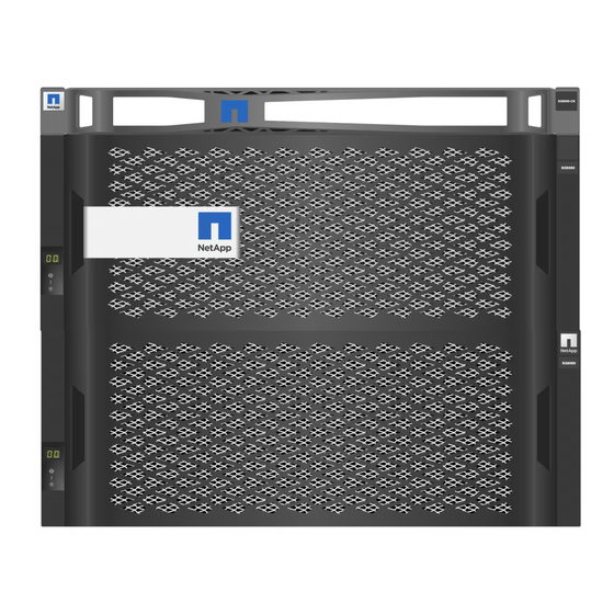
- Page 5 Callout Description SG6000-CN compute controller with front bezel E2860 controller shelf with front bezel (optional expansion shelf appears identical) SG6000-CN compute controller with front bezel removed E2860 controller shelf with front bezel removed (optional expansion shelf appears identical) This figure shows the back of the SG6060, including the compute and storage controllers, fans, and power...
- Page 6 supplies. Callout Description Power supply (1 of 2) for SG6000-CN compute controller Connectors for SG6000-CN compute controller Fan (1 of 2) for E2860 controller shelf E-Series E2800 storage controller (1 of 2) and connectors Power supply (1 of 2) for E2860 controller shelf This figure shows the back of the optional expansion shelf for the SG6060, including the input/output modules (IOMs), fans, and power supplies.
- Page 7 Callout Description Fan (1 of 2) for expansion shelf IOM (1 of 2) for expansion shelf Power supply (1 of 2) for expansion shelf SGF6024 overview The StorageGRIDSGF6024 includes a compute controller and a storage controller shelf that holds 24 solid state drives. SGF6024 components The SGF6024 appliance includes the following components: Component...
- Page 8 Component Description Flash array (controller shelf) E-Series EF570 flash array (also known as a controller shelf), a 2U shelf that includes: • Two E-Series EF570 controllers (duplex configuration) to provide storage controller failover support • 24 solid state drives (also known as SSDs or flash drives) •...
- Page 9 Controllers in SG6000 appliances Each model of the StorageGRID SG6000 appliance includes an SG6000-CN compute controller in a 1U enclosure and duplex E-Series storage controllers in a 2U or 4U enclosure, depending on the model. Review the diagrams to learn more about each type of controller.
- Page 10 Port Type Interconnect ports 1-4 16-Gb/s Fibre Channel Connect the SG6000-CN (FC), with integrated controller to the E2800 optics controllers (two connections to each E2800). Network ports 1-4 10-GbE or 25-GbE, based Connect to the Grid on cable or SFP Network and the Client transceiver type, switch Network for StorageGRID.
- Page 11 Port Type Admin Network port 2 1-GbE (RJ-45) Options: • Bond with management port 1 for a redundant connection to the Admin Network for StorageGRID. • Leave unwired and available for temporary local access (IP 169.254.0.1). • During installation, use port 2 for IP configuration if DHCP- assigned IP addresses are not...
- Page 12 Port Type Interconnect ports 1 and 2 16-Gb/s FC optical SFPa Connect each of the E2800 controllers to the SG6000-CN controller. There are four connections to the SG6000-CN controller (two from each E2800). Management ports 1 and 1-Gb (RJ-45) Ethernet •...
- Page 13 Port Type Drive expansion ports 1 12Gb/s SAS Connect the ports to the and 2 drive expansion ports on the IOMs in the expansion shelf. SGF6024: EF570 storage controllers • Two controllers for failover support. • Manage the storage of data on the drives. •...
-
Page 14: Installation And Deployment Overview
Port Type Management ports 1 and 1-Gb (RJ-45) Ethernet • Port 1 connects to the network where you access SANtricity System Manager on a browser. • Port 2 is reserved for technical support use. SG6060: Input/output modules for optional expansion shelves The expansion shelf contains two input/output modules (IOMs) that connect to the storage controllers or to other expansion shelves. - Page 15 Appliance Required StorageGRID version SGF6024 11.3 or later Installation and deployment tasks Adding a StorageGRID storage appliance to a StorageGRID system includes four primary steps: 1. Preparing for installation: ◦ Preparing the installation site ◦ Unpacking the boxes and checking the contents ◦...
-
Page 16: Prepare For Installation (Sg6000)
1. Confirm that the site meets the requirements for temperature, humidity, altitude range, airflow, heat dissipation, wiring, power, and grounding. See the NetApp Hardware Universe for more information. 2. Confirm that your location provides 240-volt AC power for the SG6060 or 120-volt AC power for the SGF6024. - Page 17 Related information NetApp Hardware Universe NetApp Interoperability Matrix Tool Unpack boxes (SG6000) Before installing the StorageGRID appliance, unpack all boxes and compare the contents to the items on the packing slip.
- Page 18 • Two front bezels • Two rail kits with instructions • 60 drives (2 SSD and 58 NL-SAS) • Four handles • Back brackets and cage nuts for square-hole rack installation...
- Page 19 SG6060 expansion shelf • Expansion shelf with no drives installed • Front bezel • 60 NL-SAS drives • One rail kit with instructions • Four handles • Back brackets and cage nuts for square-hole rack installation...
- Page 20 SGF6024 • SG6000-CN controller • EF570 flash array with 24 solid state (flash) drives installed • Two front bezels • Two rail kits with instructions • Shelf endcaps Cables and connectors The shipment for the StorageGRID appliance includes the following cables and connectors: •...
- Page 21 Your cabinet might have special power cords that you use instead of the power cords that ship with the appliance. • Optical cables and SFP transceivers Four optical cables for the FC interconnect ports Four SFP+ transceivers, which support 16-Gb/s FC •...
- Page 22 You need one of the following options: ◦ One to four TwinAx cables or optical cables for the 10/25-GbE ports you plan to use on the SG6000- CN controller ◦ One to four SFP+ transceivers for the 10/25-GbE ports if you will use optical cables and 10-GbE link speed ◦...
- Page 23 Review appliance network connections (SG6000) Before installing the StorageGRID appliance, you should understand which networks can be connected to the appliance. When you deploy a StorageGRID appliance as a Storage Node in a StorageGRID system, you can connect it to the following networks: •...
- Page 24 Related information Configure network links (SG6000) Network bond modes for 10/25-GbE ports The 10/25-GbE networking ports on the SG6000-CN controller support Fixed port bond mode or Aggregate port bond mode for the Grid Network and Client Network connections. Fixed port bond mode Fixed mode is the default configuration for the 10/25-GbE networking ports.
- Page 25 Callout Which ports are bonded All connected ports are grouped in a single LACP bond, allowing all ports to be used for Grid Network and Client Network traffic. If you plan to use aggregate port bond mode: • You must use LACP network bond mode. •...
- Page 26 Callout Network bond mode Both management ports are bonded into one logical management port connected to the Admin Network. The port on the left is connected to the Admin Network. The port on the right is available for temporary local connections (IP address 169.254.0.1).
- Page 27 Information needed Your value for controller A Your value for controller B DHCP-assigned IP address for management port 1, if available after power on Note: If the network you will connect to the storage controller includes a DHCP server, the network administrator can use the MAC address to determine the IP address that was assigned by the...
- Page 28 Information needed Your value Admin Network enabled Choose one: • No • Yes (default) Network bond mode Choose one: • Independent (default) • Active-Backup Switch port for the left port in the red circle in the diagram (default active port for Independent network bond mode) Switch port for the right port in the red circle in the diagram (Active-Backup network bond mode only)
- Page 29 Information needed to connect and configure 10/25-GbE ports on SG6000-CN controller The four 10/25-GbE ports on the SG6000-CN controller connect to the StorageGRID Grid Network and the optional Client Network. Information needed Your value Link speed Choose one: • Auto (default) •...
- Page 30 Information needed Your value Static IP address you plan to use for the appliance • IPv4 address (CIDR): Storage Node on the Grid Network • Gateway: Note: If your network does not have a gateway, specify the same static IPv4 address for the gateway. Grid Network subnets (CIDRs) Information needed to connect SG6000-CN controller to Client Network The Client Network for StorageGRID is an optional network, typically used to provide client protocol access to...
-
Page 31: Install Hardware (Sg6000)
Management Interface (IPMI) standard. Information needed Your value Ethernet switch port you will connect to the BMC management port (circled in the diagram) DHCP-assigned IP address for the BMC management • IPv4 address (CIDR): network, if available after power on •... - Page 32 Sign in with your username and password. b. Select Products > My Products. c. Confirm that the new serial number is listed. d. If it is not, follow the instructions for new NetApp customers. New NetApp customer a. Click Register Now, and create an account.
- Page 33 1. Carefully follow the instructions for the rail kit to install the rails in your cabinet or rack. For square hole cabinets, you must first install the provided cage nuts to secure the front and rear of the shelf with screws. 2.
- Page 34 7. Secure the shelf to the rear of the cabinet. Place two back brackets on each side of the upper rear section of the shelf. Insert screws into the first and third holes of each bracket. 8. Repeat these steps for any expansion shelves. SG6060: Install drives After installing the 60-drive shelf into a cabinet or rack, you must install all 60 drives into the shelf.
- Page 35 8. Install 10 HDD drives into the top drawer. 9. Slide the drawer back in by pushing on the center and closing both levers gently. Stop pushing the drawer if you feel binding. Use the release levers at the front of the drawer to slide the drawer back out.
- Page 36 1. Carefully follow the instructions for the rail kit to install the rails in your cabinet or rack. For square hole cabinets, you must first install the provided cage nuts to secure the front and rear of the shelf with screws. 2.
- Page 37 SG6000-CN: Install into cabinet or rack You must install a set of rails for the SG6000-CN controller in your cabinet or rack, and then slide the controller onto the rails. What you’ll need • You have reviewed the Safety Notices document included in the box, and understand the precautions for moving and installing hardware.
- Page 38 3. Insert the SG6000-CN controller into the rails. 4. Slide the controller into the cabinet or rack. When you cannot move the controller any further, pull the blue latches on both sides of the chassis to slide the controller all the way in.
- Page 39 Do not attach the front bezel until after you power on the controller. 5. Tighten the captive screws on the controller front panel to secure the controller in the rack. Cable appliance (SG6000) You must connect the storage controllers to the SG6000-CN controller, connect the management ports on all three controllers, and connect the network ports on the SG6000-CN controller to the Grid Network and optional Client Network for StorageGRID.
- Page 40 ◦ One to four SFP+ or SFP28 transceivers if you plan to use optical cables for the ports. Risk of exposure to laser radiation — Do not disassemble or remove any part of an SFP transceiver. You might be exposed to laser radiation. About this task The following figure shows the three controllers in the SG6060 appliance, with the SG6000-CN compute controller on the top and the two E2800 storage controllers on the bottom.
- Page 41 Port Type of port Function BMC management port 1-GbE (RJ-45) Connects to the network where you on the SG6000-CN access the BMC interface. controller FC connection ports: 16-Gb/s FC optical SFP+ Connect each storage controller to the SG6000-CN controller. • 4 on the SG6000-CN controller •...
- Page 42 3. Connect the network ports on the SG6000-CN controller to the appropriate network switches, using TwinAx cables or optical cables and SFP+ or SFP28 transceivers. The four network ports must use the same link speed. Install SFP+ transceivers if you plan to use 10-GbE link speeds.
- Page 43 Step Connect each expansion shelf to the E2860 controller shelf as shown in the diagram. This drawing shows two expansion shelves. If you have only one, connect IOM A to controller A and connect IOM B to controller B.
- Page 44 Callout Description SG6000-CN E2860 controller shelf Controller A Controller B Expansion shelf 1 IOM A for expansion shelf 1 IOM B for expansion shelf 1 Expansion shelf 2 IOM A for expansion shelf 2 IOM B for expansion shelf 2 Connect power cords and apply power (SG6000) After connecting the network cables, you are ready to apply power to the SG6000-CN controller and to the two storage controllers or optional expansion shelves.
- Page 45 8. If the power button on the front of the SG6000-CN controller is not currently illuminated blue, press the button to turn on power to the controller. Do not press the power button again during the power-on process. 9. Turn on the two power switches on the back of the storage controller shelf. If you have expansion shelves, turn on the two power switches for each shelf.
- Page 46 Display Description Identify button • Blinking or solid blue: Identifies the controller in the cabinet or rack. • Off: The controller is not visually identifiable in the cabinet or rack. This button can be set to Blink, On (Solid), or Off. Alarm LED •...
-
Page 47: Configure Hardware (Sg6000)
If you are unable to resolve the problem, contact technical support. Related information E5700 and E2800 System Monitoring Guide NetApp Support Power on SG6000-CN controller and verify operation Configure hardware (SG6000) After applying power to the appliance, you must configure the network connections that will be used by StorageGRID. - Page 48 • The client or service laptop has a supported web browser. • The SG6000-CN controller is connected to all of the StorageGRID networks you plan to use. • You know the IP address, gateway, and subnet for the SG6000-CN controller on these networks. •...
- Page 49 2. If you cannot obtain an IP address using DHCP, you can use a link-local connection. a. Connect a service laptop directly to the rightmost RJ-45 port on the SG6000-CN controller, using an Ethernet cable. b. Open a web browser on the service laptop. c.
- Page 50 The second digit in the two versions should match. For example, if your StorageGRID system is running version 11.6.x.y, the StorageGRID Appliance Installer version should be 3.6.z. 3. If the appliance has a down-level version of the StorageGRID Appliance Installer, go to the NetApp Downloads page for StorageGRID.
- Page 51 Sign in with the username and password for your NetApp account. 4. Download the appropriate version of the Support file for StorageGRID Appliances and the corresponding checksum file. The Support file for StorageGRID Appliances file is a archive that contains the current and previous .zip...
- Page 52 Callout Which ports are bonded Ports 1 and 3 are bonded together for the Client Network, if this network is used. Ports 2 and 4 are bonded together for the Grid Network. This figure shows how the four network ports are bonded in aggregate port bond mode. Callout Which ports are bonded All four ports are grouped in a single LACP bond, allowing all ports to be used for...
- Page 53 Network Client Network disabled (default) Client Network enabled bond mode LACP • Ports 2 and 4 use an LACP bond for the • Ports 2 and 4 use an LACP bond for the (802.3ad) Grid Network. Grid Network. • Ports 1 and 3 are not used. •...
- Page 54 The Link Status table lists the link state (up/down) and speed (1/10/25/40/100 Gbps) of the numbered ports. The first time you access this page: ◦ Link Speed is set to Auto. ◦ Port bond mode is set to Fixed. ◦ Network bond mode is set to Active-Backup for the Grid Network. ◦...
- Page 55 2. If you plan to use the 25-GbE link speed for the network ports, select Auto from the Link speed drop-down list. The network switches you are using for the Grid Network and the Client Network must also support and be configured for this speed.
- Page 56 The Grid Network is required. You cannot disable this network. a. If the appliance is not connected to the Admin Network, unselect the Enable network check box for the Admin Network. b. If the appliance is connected to the Client Network, select the Enable network check box for the Client Network.
- Page 57 5. When you are satisfied with your selections, click Save. You might lose your connection if you made changes to the network or link you are connected through. If you are not reconnected within 1 minute, re-enter the URL for the StorageGRID Appliance Installer using one of the other IP addresses assigned to the...
- Page 58 You must either assign a static IP for the appliance on each connected network or assign a permanent lease for the address on the DHCP server. If you want to change the link configuration, see the instructions for changing the link configuration of the SG6000-CN controller.
- Page 59 a. Enter the static IPv4 address, using CIDR notation. b. Enter the gateway. If your network does not have a gateway, re-enter the same static IPv4 address. c. If you want to use jumbo frames, change the MTU field to a value suitable for jumbo frames, such as 9000.
- Page 60 Subnet List on the primary Admin Node when you start StorageGRID installation. The default route is not listed. If the Client Network is not enabled, the default route will use the Grid Network gateway. ▪ To add a subnet, click the insert icon to the right of the last entry.
- Page 61 6. If you selected Static, follow these steps to configure the Admin Network: a. Enter the static IPv4 address, using CIDR notation, for Management Port 1 on the appliance. Management Port 1 is the left of the two 1-GbE RJ45 ports on the right end of the appliance. b.
- Page 62 c. If you want to use jumbo frames, change the MTU field to a value suitable for jumbo frames, such as 9000. Otherwise, keep the default value of 1500. The MTU value of the network must match the value configured on the switch port the node is connected to.
- Page 63 The MTU value of the network must match the value configured on the switch port the node is connected to. Otherwise, network performance issues or packet loss might occur. e. Click Save. 10. If you selected DHCP, follow these steps to configure the Client Network: a.
- Page 64 2. From the Network drop-down box, select the network you want to test: Grid, Admin, or Client. 3. Enter the IPv4 address or fully qualified domain name (FQDN) for a host on that network. For example, you might want to ping the gateway on the network or the primary Admin Node. 4.
- Page 65 Related information Configure network links (SG6000) Change MTU setting Verify port-level network connections To ensure that access between the StorageGRID Appliance Installer and other nodes is not obstructed by firewalls, confirm that the StorageGRID Appliance Installer can connect to a specific TCP port or set of ports at the specified IP address or range of addresses. About this task Using the list of ports provided in the StorageGRID Appliance Installer, you can test the connectivity between the appliance and the other nodes in your Grid Network.
- Page 66 The Grid Network ports listed in the port connectivity table are valid only for StorageGRID version 11.6.0. To verify which ports are correct for each node type, you should always consult the networking guidelines for your version of StorageGRID. Steps 1.
- Page 67 ◦ If a port-level network connection is made to the remote host, but the host is not listening on one or more of the selected ports, the “Port connectivity test failed” message appears in a yellow banner. The nmap command output is listed below the banner. Any remote port the host is not listening to has a state of “closed.”...
- Page 68 Related information Networking guidelines Access and Configure SANtricity System Manager (SG6000) You can use SANtricity System Manager to monitor the status of the storage controllers, storage disks, and other hardware components in the storage controller shelf. You can also configure a proxy for E-Series AutoSupport that enables you to send AutoSupport messages from the appliance without the use of the management port.
- Page 69 • E-Series AutoSupport settings for the components in the storage controller shelf. For additional details on E-Series AutoSupport, see the NetApp E-Series Systems Documentation Site. • Drive Security keys, which are needed to unlock secured drives (this step is required if the Drive Security feature is enabled) •...
- Page 70 Manager If these options are not available or the login page does not appear, you must use the addresses for the storage controllers. Access SANtricity System Manager by browsing to the storage controller IP. 2. Set or enter the administrator password. SANtricity System Manager uses a single administrator password that is shared among all users.
- Page 71 Configure hardware alerts. a. Select Help to access the online help for SANtricity System Manager. b. Use the Settings > Alerts section of the online help to learn about alerts. c. Follow the “How To” instructions to set up email alerts, SNMP alerts, or syslog alerts. 5.
- Page 72 c. Follow the “How To” instructions to change the password. Review hardware status in SANtricity System Manager You can use SANtricity System Manager to monitor and manage the individual hardware components in the storage controller shelf and to review hardware diagnostic and environmental information, such as component temperatures, as well as issues related to the drives.
- Page 73 4. Review the information displayed for appliance hardware and confirm that all hardware components have a status of Optimal. a. Click the Hardware tab. b. Click Show back of shelf. From the back of the shelf, you can view both storage controllers, the battery in each storage controller, the two power canisters, the two fan canisters, and expansion shelves (if any).
- Page 74 component temperatures. c. To see the settings for each storage controller, select the controller, and select View settings from the context menu. d. To see the settings for other components in the back of the shelf, select the component you want to view.
- Page 75 DHCP is the default method for assigning an IP address to the storage controller management port. It might take a few minutes for the DHCP values to appear. 5. Optionally, set a static IP address for the storage controller management port. You should either assign a static IP for the management port or assign a permanent lease for the address on the DHCP server.
- Page 76 About this task When you first install the appliance, the BMC uses a default password for the root user (root/calvin). You must change the password for the root user to secure your system. Steps 1. From the client, enter the URL for the StorageGRID Appliance Installer: https://Appliance_Controller_IP:8443 For Appliance_Controller_IP, use the IP address for the appliance on any StorageGRID network.
- Page 77 About this task For support purposes, the BMC management port allows low-level hardware access. You should only connect this port to a secure, trusted, internal management network. If no such network is available, leave the BMC port unconnected or blocked, unless a BMC connection is requested by technical support.
- Page 78 4. Optionally, set a static IP address for the BMC management port. You should either assign a static IP for the BMC management port or assign a permanent lease for the address on the DHCP server. a. Select Static. b. Enter the IPv4 address, using CIDR notation. c.
- Page 79 • The management client is using a supported web browser. Steps 1. Enter the URL for the BMC interface: https://BMC_Port_IP For BMC_Port_IP, use the DHCP or static IP address for the BMC management port. The BMC sign-in page appears. If you haven’t yet configured BMC_Port_IP, follow the instructions in Configure BMC interface (SG6000).
- Page 80 4. Optionally, create additional users by selecting Settings > User Management and clicking on any “disabled” user. When users sign in for the first time, they might be prompted to change their password for increased security. Configure SNMP settings for SG6000-CN controller If you are familiar with configuring SNMP for hardware, you can use the BMC interface to configure the SNMP settings for the SG6000-CN controller.
- Page 81 Enter the Destination IP for each SNMP trap using an IP address. Fully qualified domain names are not supported. Enable traps if you want the SG6000-CN controller to send immediate notifications to an SNMP console when it is in an unusual state. Traps might indicate hardware failures of various components or temperature thresholds being exceeded.
- Page 82 b. Add at least one user to receive alert notifications. The email address you configure for a user is the address the BMC sends alert notifications to. For example, you could add a generic user, such as “notification-user,” and use the email address of a technical support team email distribution list.
- Page 83 A KMS can be set up in Grid Manager before or after the appliance is installed in StorageGRID. See the information about KMS and appliance configuration in the instructions for administering StorageGRID for additional details. • If a KMS is set up before installing the appliance, KMS-controlled encryption begins when you enable node encryption on the appliance and add it to a StorageGRID site where KMS is configured.
- Page 84 the installation begins the appliance node accesses the KMS encryption keys in your StorageGRID system and begins disk encryption. You are not able to disable node encryption after the appliance is installed. After you add an appliance that has node encryption enabled to a StorageGRID site that has a KMS, you cannot stop using KMS encryption for the node.
- Page 85 3. On the Configure RAID Mode page, select the desired RAID mode from the Mode drop-down list. 4. Click Save. Related information NetApp E-Series Systems Documentation Site Optional: Remap network ports for appliance You might need to remap the internal ports on the appliance Storage Node to different external ports.
-
Page 86: Deploy Appliance Storage Node
5. For Original Port, enter the number of the port you want to remap. 6. For Mapped-To Port, enter the number of the port you want to use instead. 7. Click Add Rule. The new port mapping is added to the table, and the remapping takes effect immediately. 8. - Page 87 To deploy an appliance Storage Node in a StorageGRID system, you access the StorageGRID Appliance Installer and perform the following steps: • You specify or confirm the IP address of the primary Admin Node and the name of the Storage Node. •...
- Page 88 2. In the Primary Admin Node connection section, determine whether you need to specify the IP address for the primary Admin Node. If you have previously installed other nodes in this data center, the StorageGRID Appliance Installer can discover this IP address automatically, assuming the primary Admin Node, or at least one other grid node with ADMIN_IP configured, is present on the same subnet.
- Page 89 Option Description Manual IP entry a. Unselect the Enable Admin Node discovery check box. b. Enter the IP address manually. c. Click Save. d. Wait for the connection state for the new IP address to become ready. Automatic discovery of all connected primary Admin a.
-
Page 90: Monitor Storage Appliance Installation
Related information Expand your grid Recover and maintain Monitor storage appliance installation The StorageGRID Appliance Installer provides status until installation is complete. When the software installation is complete, the appliance is rebooted. Steps 1. To monitor the installation progress, click Monitor Installation. The Monitor Installation page shows the installation progress. -
Page 91: Automate Appliance Installation And Configuration (Sg6000)
4. Go to the Grid Manager of the Primary Admin node, approve the pending storage node, and complete the StorageGRID installation process. When you click Install from the Grid Manager, Stage 3 completes and stage 4, Finalize Installation, begins. When stage 4 completes, the controller is rebooted. Automate appliance installation and configuration (SG6000) You can automate the installation and configuration of your appliances and configuration of the whole StorageGRID system. - Page 92 Automating installation and configuration can be useful for deploying multiple StorageGRID instances or one large, complex StorageGRID instance. To automate installation and configuration, use one or more of the following options: • Create a JSON file that specifies the configuration settings for your appliances. Upload the JSON file using the StorageGRID Appliance Installer.
- Page 93 1. Generate the JSON file using one of the following methods: ◦ The ConfigBuilder application ConfigBuilder.netapp.com ◦ The appliance configuration script. You can download the script from configure-sga.py StorageGRID Appliance Installer (Help > Appliance Configuration Script). See the instructions on automating the configuration using the configure-sga.py script.
- Page 94 The file is uploaded and validated. When the validation process is complete, the file name is shown next to a green check mark. You might lose connection to the appliance if the configuration from the JSON file includes sections for "link_config", "networks", or both. If you are not reconnected within 1 minute, re-enter the appliance URL using one of the other IP addresses assigned to the appliance.
- Page 95 to configure. You can also use the script to generate a JSON file that contains appliance configuration information. What you’ll need • The appliance has been installed in a rack, connected to your networks, and powered on. • Network links and IP addresses have been configured for the primary Admin Node using the StorageGRID Appliance Installer.
- Page 96 Node and information about the Admin, Grid, and Client Networks. Connecting to +https://10.224.2.30:8443+ (Checking version and connectivity.) 2021/02/25 16:25:11: Performing GET on /api/versions... Received 200 2021/02/25 16:25:11: Performing GET on /api/v2/system-info... Received 2021/02/25 16:25:11: Performing GET on /api/v2/admin-connection... Received 200 2021/02/25 16:25:11: Performing GET on /api/v2/link-config...
- Page 97 Bonding mode: no-bond MAC Addresses: 00:80:e5:29:70:f4 Client Network: ENABLED Bonding mode: active-backup VLAN: novlan MAC Addresses: 00:a0:98:59:8e:89 00:a0:98:59:8e:81 Grid Network CIDR: 172.16.2.30/21 (Static) MAC: 00:A0:98:59:8E:8A Gateway: 172.16.0.1 Subnets: 172.17.0.0/21 ...
- Page 98 script from. Check that the top-level node name in the generated JSON file matches the appliance name. Do not make any changes to this file unless you are an experienced user and have a thorough understanding of StorageGRID APIs. 6. When you are satisfied with the appliance configuration, use the subcommands to install monitor...
-
Page 99: Overview Of Installation Rest Apis
For example: ./configure-storagegrid.py ./configure-storagegrid.json --start-install After you finish A Recovery Package file is generated during the configuration process, and it is downloaded to the .zip directory where you are running the installation and configuration process. You must back up the Recovery Package file so that you can recover the StorageGRID system if one or more grid nodes fails. - Page 100 StorageGRID Installation API The StorageGRID Installation API is only available when you are initially configuring your StorageGRID system, and in the event that you need to perform a primary Admin Node recovery. The Installation API can be accessed over HTTPS from the Grid Manager. To access the API documentation, go to the installation web page on the primary Admin Node and select Help >...
-
Page 101: Troubleshoot Hardware Installation (Sg6000)
Troubleshoot hardware installation (SG6000) If you encounter issues during the installation, you might find it helpful to review troubleshooting information related to hardware setup and connectivity issues. View boot-up codes for SG6000-CN controller When you apply power to the appliance, the BMC logs a series of boot-up codes for the SG6000-CN controller. - Page 102 a. Connect to the IPMI SOL using the BMC IP address and login credentials. If you haven’t changed the BMC root account password, the factory-default value might be "calvin". ipmitool -I lanplus -H BMC_Port_IP -U root -P Password sol activate b.
- Page 103 View error codes for SG6000-CN controller If a hardware error occurs when the SG6000-CN controller is booting up, the BMC logs an error code. As required, you can view these error codes using the BMC interface, and then work with technical support to resolve the issue. What you’ll need •...
- Page 104 Code Indicates 0x5B Reset PPI is not available 0x5C PEI phase BMC self-test failure 0xD0 CPU initialization error 0xD1 North bridge initialization error 0xD2 South bridge initialization error 0xD3 Some architectural protocols are not available 0xD4 PCI resource allocation error. Out of resources. 0xD5 No space for legacy option ROM 0xD6...
- Page 105 Code Indicates 0xED MRC: ERR_DIMM_COMPAT 0xEE MRC: ERR_MRC_COMPATIBILITY 0xEF MRC: ERR_MRC_STRUCT 0xF0 MRC: ERR_SET_VDD 0xF1 MRC: ERR_IOT_MEM_BUFFER 0xF2 MRC: ERR_RC_INTERNAL 0xF3 MRC: ERR_INVALID_REG_ACCESS 0xF4 MRC: ERR_SET_MC_FREQ 0xF5 MRC: ERR_READ_MC_FREQ 0x70 MRC: ERR_DIMM_CHANNEL 0x74 MRC: ERR_BIST_CHECK 0xF6 MRC: ERR_SMBUS 0xF7 MRC: ERR_PCU 0xF8 MRC: ERR_NGN 0xF9...
- Page 106 Related information View boot-up status codes for SG6000 storage controllers E5700 and E2800 System Monitoring Guide View status indicators and buttons on SG6000-CN controller View boot-up codes for SG6000-CN controller View error codes for SG6000-CN controller Troubleshoot connection issues (SG6000) If you encounter connection issues during the StorageGRID appliance installation, you should perform the corrective action steps listed.
- Page 107 link-local IP to check controller networking configuration and update if necessary. For 169.254.0.1 detailed instructions, see step 2 in Accessing StorageGRID Appliance Installer. If that does not resolve the issue, contact technical support. e. If the ping was successful, open a web browser. f.
-
Page 108: Maintain Sg6000 Appliance
Installer is running. For example, you might need to reboot the controller if the installation fails. About this task This procedure only applies when the SG6000-CN controller is running the StorageGRID Appliance Installer. Once the installation is completed, this step no longer works because the StorageGRID Appliance Installer is no longer available. - Page 109 Place appliance into maintenance mode You must place the appliance into maintenance mode before performing specific maintenance procedures. What you’ll need • You are signed in to the Grid Manager using a supported web browser. • You have the Maintenance or Root access permission. For details, see the instructions for administering StorageGRID.
- Page 110 5. Enter the provisioning passphrase, and select OK. A progress bar and a series of messages, including including "Request Sent," "Stopping StorageGRID," and "Rebooting," indicate that the appliance is completing the steps for entering maintenance mode. When the appliance is in maintenance mode, a confirmation message lists the URLs you can use to access the StorageGRID Appliance Installer.
- Page 111 6. To access the StorageGRID Appliance Installer, browse to any of the URLs displayed. If possible, use the URL containing the IP address of the appliance’s Admin Network port. If you have a direct connection to the appliance’s management port, use to access the StorageGRID Appliance Installer page.
- Page 112 To ensure optimal functioning of the storage controller, you must upgrade to the latest maintenance release of the SANtricity OS that is qualified for your StorageGRID appliance. Consult the NetApp Interoperability Matrix Tool (IMT) to determine which version you should be using. If you need assistance, contact technical support.
- Page 113 Grid Manager to apply an upgrade. What you’ll need • You have consulted the NetApp Interoperability Matrix Tool (IMT) to confirm that the SANtricity OS version you are using for the upgrade is compatible with your appliance.
- Page 114 NetApp Downloads: SANtricity OS 2. Select MAINTENANCE > System > Software update. 3. In the SANtricity OS update section, select Update. The SANtricity OS upgrade page appears. 4. Select the SANtricity OS upgrade file you downloaded from the NetApp support site.
- Page 115 a. Select Browse. b. Locate and select the file. c. Select Open. The file is uploaded and validated. When the validation process is done, the file name is shown next to the Browse button. Do not change the file name since it is part of the verification process. 5.
- Page 116 When the SANtricity OS upgrade starts: a. The health check is run. This process checks that no nodes have the status of Needs Attention. If any errors are reported, resolve them and select Start again. b. The SANtricity OS Upgrade Progress table appears. This table shows all Storage Nodes in your grid and the current stage of the upgrade for each node.
- Page 117 Do not approve the SANtricity OS upgrade for an appliance storage node unless you are sure the node is ready to be stopped and rebooted. When the SANtricity OS upgrade is approved on a node, the services on that node are stopped and the upgrade process begins.
- Page 118 12. If a node cannot be upgraded, note the reason shown in the Details column and take the appropriate action: ◦ “Storage Node was already upgraded.” No further action required. ◦ “SANtricity OS upgrade is not applicable to this node.” The node does not have a storage controller that can be managed by the StorageGRID system.
- Page 119 What you’ll need • You have consulted the NetApp Interoperability Matrix Tool (IMT) to confirm that the SANtricity OS version you are using for the upgrade is compatible with your appliance.
- Page 120 (no icons to the left of the node name) for the appliance node, indicating that no alerts are active and the node is connected to the grid. Related information NetApp Interoperability Matrix Tool Upgrade SANtricity OS on storage controllers using Grid Manager...
- Page 121 Upgrade drive firmware using SANtricity System Manager You upgrade your drive firmware to make sure you have all the latest features and bug fixes. What you’ll need • The storage appliance has an Optimal status. • All drives have an Optimal status. •...
- Page 122 4. Download and prepare the available drive firmware upgrade: a. Under Drive Firmware upgrade, select NetApp Support. b. On the NetApp Support web site, select the Downloads tab, and then select E-Series Disk Drive Firmware. The E-Series Disk Firmware page displays.
- Page 123 d. If a later firmware revision is listed, select the link in the Firmware Rev. (Download) column to download archive containing the firmware file. .zip e. Extract (unzip) the drive firmware archive files you downloaded from the Support site. 5. Install the drive firmware upgrade: a.
- Page 124 Any firmware downloads that have not started are canceled. Stopping the drive firmware upgrade might result in data loss or unavailable drives. g. (Optional) To see a list of what was upgraded, select Save Log. The log file is saved in the downloads folder for your browser with the name latest-upgrade-log- timestamp.txt.
- Page 125 this issue. ▪ SPM Verify Database Controller check fails A storage partitions mapping database error occurred on a controller. Contact technical support to resolve this issue. ▪ Configuration Database Validation (If supported by the storage array’s controller version) A configuration database error occurred on a controller. Contact technical support to resolve this issue.
- Page 126 It can take up to 20 minutes for the appliance to reboot and rejoin the grid. To confirm that the reboot is complete and that the node has rejoined the grid, go back to the Grid Manager. The Nodes page should display a normal status (no icons to the left of the node name) for the appliance node, indicating that no alerts are active and the node is connected to the grid.
- Page 127 What you’ll need • You must have the provisioning passphrase. • You must be running StorageGRID 11.4 or later. • You have the expansion shelf and two SAS cables for each expansion shelf. • You have physically located the storage appliance where you are adding the expansion shelf in the data center.
- Page 128 Callout Description SG6000-CN...
- Page 129 Callout Description E2860 controller shelf Controller A Controller B Expansion shelf 1 IOM A for expansion shelf 1 IOM B for expansion shelf 1 Expansion shelf 2 IOM A for expansion shelf 2 IOM B for expansion shelf 2 5. Connect the power cords and apply power to the expansion shelves. a.
- Page 130 Expansion shelves that are already deployed are not included in this message. They are included in the count in the banner at the top of the page. ▪ The message will not appear if new expansion shelves are not detected. 7.
- Page 131 When configuration is complete, the appliance automatically reboots to exit maintenance mode and rejoin the grid. This process can take up to 20 minutes. To retry the expansion shelf configuration if it fails, go to the StorageGRID Appliance Installer, select Advanced > Reboot Controller, and then select Reboot into Maintenance Mode.
- Page 132 SG6060: Install drives Monitor and troubleshoot Turn controller identify LED on and off The blue identify LED on the front and back of the controller can be turned on to help locate the appliance in a data center. What you’ll need You must have the BMC IP address of the controller you want to identify.
- Page 133 If a bezel is installed on the controller, it might be difficult to see the front identify LED. After you finish To turn off the controller identify LED: • Press the identify LED switch on the controller front panel. • From the controller BMC interface, select Server Identify, select OFF and then select Perform Action. The blue identify LEDs on the front and rear of the controller go off.
- Page 134 ◦ Check the tags attached to the front of each controller for a matching part number. 2. Remove the controller front bezel, if one is installed, to access the front panel controls and indicators. 3. Optional: Turn off the blue identify LED if you used it to locate the controller. ◦...
- Page 135 About this task You can determine if you have a failed controller in two ways: • The Recovery Guru in SANtricity System Manager directs you to replace the controller. • The amber Attention LED on the controller is on, indicating that the controller has a fault. If both controllers in the shelf have their Attention LEDs on, contact technical support for assistance.
- Page 136 Label Label Description MAC address The MAC address for management port 1 (“P1”). If you used DHCP to obtain the original controller’s IP address, you will need this address to connect to the new controller. FRU part number The FRU part number. This number must match the replacement part number for the currently installed controller.
- Page 137 Always use two hands to support the weight of the controller. e. Place the controller on a flat, static-free surface with the removable cover facing up. f. Remove the cover by pressing down on the button and sliding the cover off. 5.
- Page 138 Item Description Battery release latch Battery d. Lift up on the battery, and slide it out of the controller. e. Remove the cover from the replacement controller. f. Orient the replacement controller so that the slot for the battery faces toward you. g.
- Page 139 Possible hardware damage — The metal flange at the front of the battery must be completely inserted into the slot on the controller (as shown in the first figure). If the battery is not installed correctly (as shown in the second figure), the metal flange might contact the controller board, causing damage.
- Page 140 8. Confirm that the new controller is Optimal, and collect support data. Related information NetApp E-Series Systems Documentation Site Replace hardware components in storage controller shelf If a hardware problem occurs, you might need to replace a component in the storage controller shelf.
- Page 141 Drive drawer (60-drive shelves only) E-Series: Replace drive drawer (60-drive) Related information NetApp E-Series Systems Documentation Site Replace storage controller Replace hardware components in optional 60-drive expansion shelf You might need to replace an input/output module, a power supply, or a fan in the expansion shelf.
- Page 142 About this task To prevent service interruptions, confirm that all other Storage Nodes are connected to the grid before shutting down the controller or shut down the controller during a scheduled maintenance window when periods of service disruption are acceptable. See the information about determining node connection states in the instructions for managing objects with information lifecycle management.
- Page 143 ◦ Use the controller BMC interface: i. Access the controller BMC interface. Access BMC interface ii. Select Power Control. iii. Verify that the Power Actions indicates that the host is currently off. Related information Remove SG6000-CN controller from cabinet or rack...
- Page 144 Power on SG6000-CN controller and verify operation Power on the controller after completing maintenance. What you’ll need • You have installed the controller in a cabinet or rack and connected the data and power cables. Reinstall SG6000-CN controller into cabinet or rack •...
- Page 145 Use the BMC interface to monitor start-up status. 2. Confirm that the appliance controller displays in the Grid Manager and with no alerts. It might take up to 20 minutes for the controller to display in the Grid Manager. 3. Confirm that the new SG6000-CN controller is fully operational: a.
- Page 146 Online Online Online Online If the expected output is not returned, contact technical support. c. Enter the following command and verify that it returns the expected output: cat /sys/class/fc_host/*/speed Expected output: 16 Gbit 16 Gbit 16 Gbit 16 Gbit If the expected output is not returned, contact technical support. d.
- Page 147 If you are replacing the controller before installing StorageGRID software, you might not be able to access the StorageGRID Appliance Installer immediately after completing this procedure. While you can access the StorageGRID Appliance Installer from other hosts on the same subnet as the appliance, you cannot access it from hosts on other subnets.
- Page 148 d. Replace the cables and any SFP+ or SFP28 transceivers. e. Power on the controller and monitor the controller LEDs and boot-up codes. 5. Confirm that the appliance Storage Node appears in the Grid Manager and that no alarms appear. 6.
- Page 149 Steps 1. If you are replacing only one power supply, you don’t need to shut down the appliance. Go to the Unplug the power cord step. If you are replacing both power supplies at the same time, do the following before unplugging the power cords: Place the appliance into maintenance mode.
- Page 150 5. With the blue latch on the right, slide the replacement power supply into the chassis. Both power supplies must be the same model and wattage. Ensure that the blue latch is on the right side when you slide the replacement unit in. 6.
- Page 151 3. Label and then disconnect the controller data cables and any SFP+ or SFP28 transceivers. To prevent degraded performance, do not twist, fold, pinch, or step on the cables. 4. Loosen the two captive screws on the controller front panel. 5.
- Page 152 Do not attach the front bezel until after you power on the controller. 2. Tighten the captive screws on the controller front panel to secure the controller in the rack. 3. Wrap the strap end of the ESD wristband around your wrist, and secure the clip end to a metal ground to prevent static discharge.
- Page 153 Remove SG6000-CN controller cover Remove the controller cover to access internal components for maintenance. What you’ll need Remove the controller from the cabinet or rack to access the top cover. Remove SG6000-CN controller from cabinet or rack Steps 1. Make sure that the SG6000-CN controller cover latch is not locked. If necessary, turn the blue plastic latch lock one-quarter turn in the unlock direction, as shown on the latch lock.
- Page 154 2. Rotate the cover latch forward and down until it stops and the cover fully seats into the chassis. Verify that there are no gaps along the front edge of the cover. If the cover is not fully seated, you might not be able to slide the SG6000-CN controller into the rack. 3.
- Page 155 Check the Storage appliance chassis serial number and the Compute controller serial number in the StorageGRID Appliance section. See if one of these serial numbers matches the serial number of the storage appliance where you are replacing the Fibre Channel HBA. If either serial number matches, you have found the correct appliance.
- Page 156 controller BMC IP address listed the StorageGRID Appliance section. You can use this IP address to turn on the compute controller identify LED, to help you locate the appliance in the data center. Turn the controller identify LED on and off Related information Remove Fibre Channel HBA Remove Fibre Channel HBA...
- Page 157 3. Grasp the riser assembly through the blue-marked holes and carefully lift it upwards. Move the riser assembly toward the front of the chassis as you lift it to allow the external connectors in its installed adapters to clear the chassis. 4.
- Page 158 Reinstall Fibre Channel HBA Administer StorageGRID Monitor and troubleshoot Manage objects with ILM Reinstall Fibre Channel HBA The replacement Fibre Channel HBA is installed into the same location as the one that was removed. What you’ll need • You have the correct replacement Fibre Channel HBA. •...
- Page 159 5. Position the riser assembly in the chassis, making sure that it aligns with the connector and guide pin on the system board; then, insert the riser assembly. 6. Carefully press the riser assembly in place along its center line, next to the blue-marked holes, until it is fully seated.
- Page 160 Make the desired changes to the link configuration. For more information on the options, see Configure network links (SG6000). 3. When you are satisfied with your selections, click Save. You might lose your connection if you made changes to the network or link you are connected through.
- Page 161 It can take up to 20 minutes for the appliance to reboot and rejoin the grid. To confirm that the reboot is complete and that the node has rejoined the grid, go back to the Grid Manager. The NODES page should display a normal status (no icon) for the appliance node, indicating that no alerts are active and the node is connected to the grid.
- Page 162 For the best network performance, all nodes should be configured with similar MTU values on their Grid Network interfaces. The Grid Network MTU mismatch alert is triggered if there is a significant difference in MTU settings for the Grid Network on individual nodes. The MTU values do not have to be the same for all network types.
- Page 163 3. When you are satisfied with the settings, select Save. 4. If this procedure completed successfully and you have additional procedures to perform while the node is in maintenance mode, perform them now. When you are done, or if you experienced any failures and want to start over, select Advanced >...
- Page 164 It can take up to 20 minutes for the appliance to reboot and rejoin the grid. To confirm that the reboot is complete and that the node has rejoined the grid, go back to the Grid Manager. The NODES page should display a normal status (no icon) for the appliance node, indicating that no alerts are active and the node is connected to the grid.
- Page 165 The appliance has been placed maintenance mode. About this task You might need to change the DNS server settings if an encrypted appliance cannot connect to the key management server (KMS) or KMS cluster because the hostname for the KMS was specified as a domain name instead of an IP address.
- Page 166 The node uses the DNS server settings specified on this page to reconnect to the KMS, allowing data on the node to be decrypted. 5. After node data is decrypted, reboot the node. From the StorageGRID Appliance Installer, select Advanced > Reboot Controller, and then select one of these options: ◦...
- Page 167 Monitor node encryption in maintenance mode (SG6000) If you enabled node encryption for the appliance during installation, you can monitor the node-encryption status of each appliance node, including the node-encryption state and key management server (KMS) details. What you’ll need •...
- Page 168 The Node Encryption page includes these three sections: ◦ Encryption Status shows whether node encryption is enabled or disabled for the appliance. ◦ Key Management Server Details shows information about the KMS being used to encrypt the appliance. You can expand the server and client certificate sections to view certificate details and status.
- Page 169 all data from the appliance. You must clear the KMS key before you can install the appliance into another StorageGRID system. Clearing the KMS configuration deletes data from the appliance, rendering it permanently inaccessible. This data is not recoverable. 2. When you are done checking node-encryption status, reboot the node. From the StorageGRID Appliance Installer, select Advanced >...
- Page 170 Related information Administer StorageGRID Clear key management server configuration Clearing the key management server (KMS) configuration disables node encryption on your appliance. After clearing the KMS configuration, the data on your appliance is permanently deleted and is no longer accessible. This data is not recoverable. What you’ll need If you need to preserve data on the appliance, you must either perform a node decommission procedure or clone the node before you clear the KMS configuration.
- Page 171 Do not clear the KMS configuration if you plan to reinstall an appliance node in a StorageGRID system that uses the same KMS key. • Before you can recover and reinstall a node where the KMS configuration was lost and the KMS key is not recoverable.
- Page 172 If the KMS configuration is cleared, data on the appliance will be permanently deleted. This data is not recoverable. 3. At the bottom of the window, select Clear KMS Key and Delete Data. 4. If you are sure that you want to clear the KMS configuration, type clear and select Clear KMS Key and Delete Data.
- Page 173 The KMS encryption key and all data are deleted from the node, and the appliance reboots. This can take up to 20 minutes. 5. Open a browser, and enter one of the IP addresses for the appliance’s compute controller. https://Controller_IP:8443 is the IP address of the compute controller (not the storage controller) on any of the Controller_IP three StorageGRID networks.
- Page 174 NetApp. The use or purchase of this product does not convey a license under any patent rights, trademark rights, or any other intellectual property rights of NetApp.
Need help?
Do you have a question about the StorageGRID SG6000 and is the answer not in the manual?
Questions and answers