
Subscribe to Our Youtube Channel
Related Manuals for WAGO TEchDocs 765-4501/0100-0000


Summary of Contents for WAGO TEchDocs 765-4501/0100-0000
- Page 1 WAGO I/O System Field 8-Port IO-Link Master Class A; EtherNet/IP; 24 V DC; 2.0 A; 8 × M12 Connection 765-4501/0100-0000 Product manual | Version 1.1.0...
- Page 2 We wish to point out that the software and hardware terms as well as the trademarks of companies used and/or mentioned in the present manual are generally protected by trademark or patent. WAGO is a registered trademark of WAGO Verwaltungsgesellschaft mbH. Product manual | Version: 1.1.0 8PORT IOL-A FLD EI DC 24V 2.0A...
-
Page 3: Table Of Contents
765-4501/0100-0000 Table of Contents Table of Contents Provisions......................... 7 Document Portfolio.................... 7 Intended Use ...................... 7 Typographical Conventions.................. 9 Legal Information .................... 11 Safety .......................... 12 General Safety Rules .................... 12 Electrical Safety..................... 12 Mechanical Safety .................... 13 Thermal Safety ...................... 13 Indirect Safety ....................... - Page 4 Table of Contents 765-4501/0100-0000 5.5.2 WAGO IO-Link Configurator................. 51 5.5.3 WAGO Webserver I/O Field ................. 51 5.5.4 WAGO I/O Field app .................. 52 Communication Interfaces.................. 53 5.6.1 EtherNet/IP .................... 54 5.6.1.1 Event Log Object 65 ................ 54 5.6.2 OPC UA Server .................... 54 Planning .......................... 55...
- Page 5 Forcing for IO-Link Ports............ 110 10.3.2 WAGO IO-Link Configurator............... 111 10.3.3 WAGO I/O Field app .................. 111 10.3.3.1 Parameterizing a Module with the WAGO I/O Field App .... 111 10.3.4 OPC UA Server .................. 111 10.3.4.1 Parameterizing the Product via OPC UA........... 112 10.3.4.1.1 Identifying Devices..............
- Page 6 Table of Contents 765-4501/0100-0000 12.2 Updating Firmware .................... 126 Decommissioning ...................... 127 13.1 Entsorgung und Recycling .................. 127 Appendix........................ 128 14.1 Installation Regulations Specified by Approvals .......... 128 14.2 Operational Description.................. 129 14.3 Protected Rights.................... 130 Product manual | Version: 1.1.0 8PORT IOL-A FLD EI DC 24V 2.0A...
-
Page 7: Provisions
ü www.wago.com All documentation is available at: /<item number>. Besides this documentation, the following supplementary document is available: & Product Manual WAGO IO-Link Configurator • 1.2 Intended Use The product 0765-4501/0100-0000 is used to capture field signals on sensors, actuators and hubs which have been sent or received by a higher-level controller and output them via IO-Link. - Page 8 The terms set forth in the General Business and Contract Conditions for Delivery and Service of WAGO Kontakttechnik GmbH & Co. KG and the terms for software products and products with integrated software stated in the WAGO Software License Contract –...
- Page 9 765-4501/0100-0000 Provisions 1.3 Typographical Conventions Number Notation Decimals: Normal notation 0x64 Hexadecimals: C-notation ‘100’ Binary: In single quotation marks ‘0110.0100’ Nibbles separated by a period Text Formatting italic Names of paths or files bold Menu items, entry or selection fields, emphasis Sections of program code Code >...
- Page 10 Provisions 765-4501/0100-0000 WARNING Type and source of hazard Possible consequences of hazard that also include severe injury • Action step to reduce risk CAUTION Type and source of hazard Possible consequences of hazard that include at least slight injury • Action step to reduce risk NOTICE Type and source of malfunction (property damage only)
-
Page 11: Legal Information
Third-party products are always mentioned without any reference to patent rights. WAGO Kontakttechnik GmbH & Co. KG, or for third-party products, their manufacturer, retain all rights regarding patent, utility model or design registration. -
Page 12: Safety
Safety 765-4501/0100-0000 Safety This section contains safety rules that must be followed for hazard-free use of the prod- uct. This section is aimed at the following target groups: • Planners and installers • Operators • Qualified assembly personnel • Qualified installation personnel (electrical installation, technician network installation etc.) •... -
Page 13: Mechanical Safety
In addition, note the information on the product housing and further infor- mation, e.g. at ü www.wago.com/<item number>. • Only permit skilled personnel approved by WAGO to perform repair work. Product manual | Version: 1.1.0 8PORT IOL-A FLD EI DC 24V 2.0A... -
Page 14: Overview
765-4501/0100-0000 Overview The product is part of the WAGO I/O System Field 765. It is intended for industrial use within an ETHERNET network and communicates with a central controller and/or directly with the control level, if necessary. Several sensors/actuators can be connected to the product for connection in the field level. -
Page 15: Properties
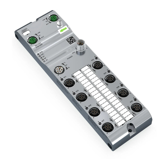
765-4501/0100-0000 Properties Properties 4.1 View Figure 1: View Table 3: Legend for “View” Figure Function Position Custom Name Description ETHERNET ETHERNET interface, M12, D-coded, EtherNet/IP port 1 Product manual | Version: 1.1.0 8PORT IOL-A FLD EI DC 24V 2.0A... - Page 16 Properties 765-4501/0100-0000 Function Position Custom Name Description LNK (X21) Link LED for port X21 ACT (X21) Activity LED for port X21 ETHERNET interface, M12, D-coded, EtherNet/IP port 2 LNK (X22) Link LED for port X22 ACT (X22) Activity LED for port X22 ®...
-
Page 17: Connections
765-4501/0100-0000 Properties 4.2 Connections 4.2.1 Power supply The product is powered through the X31 connection (Power in). Two supply cables can be connected to the plug: • Supply cable 1: 1L+ (U ) and reference potential 1L− • Supply cable 2: 2L+ (U ) and reference potential 2L−... -
Page 18: Network Connections
Properties 765-4501/0100-0000 4.2.3 Network Connections 4.2.3.1 ETHERNET Interfaces Table 6: ETHERNET Interfaces ETHERNET Signal Description Positive send data Positive receive data TX– Negative send data RX– Negative receive data Housing Shield Shield connection; housing is connected to functional ground M12, D-coded, socket, 4-pin 4.3 Circuit Diagram The following figure shows the schematic circuit diagram of the product. -
Page 19: Technical Data
765-4501/0100-0000 Properties 4.4 Technical data 4.4.1 Product Table 7: Product Property Value Item Number 0765-4501/0100-0000 Product function 8-Port-IO-Link Master Class A Product name (short) 8 PORT IOL-A FLD EI 24 VDC 2.0 A Product name (long) 8-Port IO-Link Master Class A; EtherNet/IP; 24 V DC; 2.0 A;... -
Page 20: Connection Technology
Properties 765-4501/0100-0000 4.4.3 Connection Technology Table 9: Connection technology Property Value Power connection PWR IN: M12 L-coded, 5-pin, plug PWR OUT: M12 L-coded, 5-pin, socket EtherNet/IP connection 2 × M12, D-coded, socket, 4-pin IO-Link ports 8 × M12, A-kodiert, Buchse, 5-polig Tightening torque M12: 1.0 Nm IO-Link Port (Class A) - Page 21 765-4501/0100-0000 Properties Property Value Output current, L1 Maximum: 4.0 A per channel per IEC 61131-2 Output current, L1 with IO-Link operating mode Maximum 1.0 A with conductor size AWG 22/0.34 mm and cable length of up to 20 m (per IO-Link specifica- tion) Maximum 4.0 A with increased conductor cross-sec- tion or reduced cable length (max.
-
Page 22: Power Supply
Properties 765-4501/0100-0000 4.4.4 Power Supply Table 11: Power supply Parameters Value Supply voltage, 1L, 2L 24 VDC, –25 %/+30 % (18 VDC … 31.2 VDC) Voltages above 34 V can permanently damage the de- vice. Voltages below approx. 11 V lead to device reset. Undervoltage warning, 1L 18.0 V (± 5 % at 25 °C) message On, 18.3 V (± 5 % at 25 °C) message Off Overvoltage warning, 1L 30.0 V (± 5 % at 25 °C) message On,... -
Page 23: Electrical Safety
765-4501/0100-0000 Properties 4.4.5 Electrical Safety Table 12: Electrical Safety Property Value Insulation resistance 60 VDC Test voltage 550 VAC RMS Min. creepage distance 0.7 mm Requirements • Use of PELV/SELV power supplies (limited to 60 VDC) • When SELV power supplies are used: SELV power supplies with supply via the same network phase •... -
Page 24: Table 16 Opc Ua Server
Table 16: OPC UA Server Parameters Value OPC UA Server Per “IO-Link Companion Specification”: http://opcfoundation.org/UA/IOLink/ Manufacturer-specific information model with diagnos- tic functions: http://www.wago.com/UA/Diagnostics/ Server profile Micro Embedded Device Protocol OPC UA TCP User access Anonymous (read access only) Username/password (read and write access) -
Page 25: Derating
The product provides measured values for temperature and current, which you can display with WAGO Webserver I/O Field or read out via OPC UA. The following figure shows the maximum permissible current (I) that can flow into the product as a function of the surrounding air temperature (T). -
Page 26: Regulations And Standards
Certificate number: R20-0935-01-TEC (Wideline) FCC ID: 2AKUE-WIDELINE ISED Certificate number: 22322-WIDELINE Note More information on approvals You can find detailed information on the approvals online at: ü www.wago.com/<item number> Product manual | Version: 1.1.0 8PORT IOL-A FLD EI DC 24V 2.0A... -
Page 27: Functions
765-4501/0100-0000 Functions Functions 5.1 Process Image This section describes the process data. The structure of the process data depends on which connection (connection 1, connection 2 etc.) is used between the EtherNet/IP scanner and the module. The module offers multiple connections; a connection was se- lected during configuration of the EtherNet/IP scanner. - Page 28 Functions 765-4501/0100-0000 Byte Off- Byte Input Process Data Description Count Byte 8 ... 38: reserved. Port X02: IO-Link PQI 8 Process Image [} 47]. Dummy byte Reserved, 0 41 ... 72 Port X02 (pin 4) functions as IO- IO-Link input data of the IO-Link device on port X02. Link master: IO-Link input data For a description of the data, see the manual from the manufacture of the IO-Link device used.
-
Page 29: Table 20 Process Data Of The Digital Inputs (Port-Based Assignment)
765-4501/0100-0000 Functions Byte Off- Byte Input Process Data Description Count Port X05 (pin 4) functions as Byte 143: digital output: output data Bit 0 = 0: output off. Bit 0 = 1: Input on. Bits 1 ... 7: always 0. Byte 144 ... -
Page 30: Table 21 Process Data Of The Digital Inputs (Pin-Based Assignment)
Functions 765-4501/0100-0000 Byte Off- Input Process Data Port X01, pin 2: DI B or mirrored DO B (depending on configuration) Port X04, pin 4: DI A or mirrored DO A (depending on configuration) Port X04, pin 2: DI B or mirrored DO B (depending on configuration) Port X05, pin 4: DI A or mirrored DO A (depending on configuration) Port X05, pin 2: DI B or mirrored DO B (depending on configuration) Port X08, pin 4: DI A or mirrored DO A (depending on configuration) Port X08, pin 2: DI B or mirrored DO B (depending on configuration) - Page 31 765-4501/0100-0000 Functions Byte Off- Byte Input Process Data Description Count Byte 8 ... 22: reserved. Port X02: IO-Link PQI 8 Process Image [} 47]. Dummy byte Reserved, 0 25 ... 40 Port X02 (pin 4) functions as IO- IO-Link input data of the IO-Link device on port X02. Link master: IO-Link input data For a description of the data, see the manual from the manufacture of the IO-Link device used.
-
Page 32: Table 23 Process Data Of The Digital Inputs (Port-Based Assignment)
Functions 765-4501/0100-0000 Byte Off- Byte Input Process Data Description Count Port X05 (pin 4) functions as Byte 79: digital output: output data Bit 0 = 0: output off. Bit 0 = 1: Input on. Bits 1 ... 7: always 0. Byte 80 ... -
Page 33: Table 24 Process Data Of The Digital Inputs (Pin-Based Assignment)
765-4501/0100-0000 Functions Byte Off- Input Process Data Port X01, pin 2: DI B or mirrored DO B (depending on configuration) Port X04, pin 4: DI A or mirrored DO A (depending on configuration) Port X04, pin 2: DI B or mirrored DO B (depending on configuration) Port X05, pin 4: DI A or mirrored DO A (depending on configuration) Port X05, pin 2: DI B or mirrored DO B (depending on configuration) Port X08, pin 4: DI A or mirrored DO A (depending on configuration) Port X08, pin 2: DI B or mirrored DO B (depending on configuration) - Page 34 Functions 765-4501/0100-0000 Byte Off- Byte Input Process Data Description Count Byte 8 ... 10: reserved. Port X02: IO-Link PQI 8 Process Image [} 47]. Dummy byte Reserved, 0 13 ... 16 Port X02 (pin 4) functions as IO- IO-Link input data of the IO-Link device on port X02. Link master: IO-Link input data For a description of the data, see the manual from the manufacture of the IO-Link device used.
-
Page 35: Table 26 Process Data Of The Digital Inputs (Port-Based Assignment)
765-4501/0100-0000 Functions Byte Off- Byte Input Process Data Description Count Port X05 (pin 4) functions as Byte 31: digital output: output data Bit 0 = 0: output off. Bit 0 = 1: Input on. Bits 1 ... 7: always 0. Byte 32 ... -
Page 36: Table 27 Process Data Of The Digital Inputs (Pin-Based Assignment)
Functions 765-4501/0100-0000 Byte Off- Input Process Data Port X01, pin 2: DI B or mirrored DO B (depending on configuration) Port X04, pin 4: DI A or mirrored DO A (depending on configuration) Port X04, pin 2: DI B or mirrored DO B (depending on configuration) Port X05, pin 4: DI A or mirrored DO A (depending on configuration) Port X05, pin 2: DI B or mirrored DO B (depending on configuration) Port X08, pin 4: DI A or mirrored DO A (depending on configuration) Port X08, pin 2: DI B or mirrored DO B (depending on configuration) - Page 37 765-4501/0100-0000 Functions Byte Off- Byte Output Process Data Description Count Port X01 (pin 4) functions as Byte 7: digital output: output data Bit 0 = 0: output off. Bit 0 = 1: Input on. Bits 1 ... 7: always 0. Byte 8 ...
- Page 38 Functions 765-4501/0100-0000 Byte Off- Byte Output Process Data Description Count 143 ... Port X05 functions as IO-Link IO-Link output data of the IO-Link device on port X05. master: IO-Link output data For a description of the data, see the manual from the manufacture of the IO-Link device used.
-
Page 39: Table 29 Process Data Of The Digital Outputs (Port-Based Assignment)
765-4501/0100-0000 Functions Table 29: Process Data of the Digital Outputs (Port-Based Assignment) Byte Off- Output Process Data Port X01, pin 2: DO B Port X04, pin 2: DO B Port X05, pin 2: DO B Port X08, pin 2: DO B Table 30: Process Data of the Digital Outputs (Pin-Based Assignment) Byte Off- Output Process Data... - Page 40 Functions 765-4501/0100-0000 Byte Off- Byte Output Process Data Description Count 7 ... 22 Port X01 (pin 4) functions as a Reserved, 0 digital input Dummy byte Reserved, 0 Port X01 functions as IO-Link IO-Link output data of the IO-Link device on port X01. master: IO-Link output data For a description of the data, see the manual from the manufacture of the IO-Link device used.
- Page 41 765-4501/0100-0000 Functions Byte Off- Byte Output Process Data Description Count Dummy byte Reserved, 0 61 ... 76 Port X04 functions as IO-Link IO-Link output data of the IO-Link device on port X04. master: IO-Link output data For a description of the data, see the manual from the manufacture of the IO-Link device used.
-
Page 42: Table 32 Process Data Of The Digital Outputs (Port-Based Assignment)
Functions 765-4501/0100-0000 Byte Off- Byte Output Process Data Description Count Port X07 (pin 4) functions as a Reserved, 0 digital input Dummy byte Reserved, 0 115 ... Port X07 functions as IO-Link IO-Link output data of the IO-Link device on port X07. master: IO-Link output data For a description of the data, see the manual from the manufacture of the IO-Link device used. -
Page 43: Table 33 Process Data Of The Digital Outputs (Pin-Based Assignment)
765-4501/0100-0000 Functions Table 33: Process Data of the Digital Outputs (Pin-Based Assignment) Byte Off- Output Process Data Port X01, pin 2: DO B Port X02, pin 2: DO B Port X07, pin 2: DO B Port X08, pin 2: DO B Output Process Data of Connections 7 and 8 Connections 7 and 8 have no output process data. - Page 44 Functions 765-4501/0100-0000 Byte Off- Byte Output Process Data Description Count Port X02 (pin 4) functions as 0: Port X02 pin 4 output data invalid. Substitute value digital output: output release is used. 1–255: Port X02 pin 4 output data valid. Port X02 (pin 4) functions as a Reserved, 0 digital input...
- Page 45 765-4501/0100-0000 Functions Byte Off- Byte Output Process Data Description Count Port X05 functions as IO-Link 0: IO-Link port X05 output data invalid. master: IO-Link output data re- 1–255: IO-Link port X05 output data valid. lease Port X05 (pin 4) functions as 0: Port X05 pin 4 output data invalid.
-
Page 46: Table 35 Process Data Of The Digital Outputs (Port-Based Assignment)
Functions 765-4501/0100-0000 Byte Off- Byte Output Process Data Description Count Port X07 (pin 4) functions as a Reserved, 0 digital input Port X08 functions as IO-Link 0: IO-Link port X08 output data invalid. master: IO-Link output data re- 1–255: IO-Link port X08 output data valid. lease Port X08 (pin 4) functions as 0: Port X08 pin 4 output data invalid. -
Page 47: Forcing
The “Forcing” function can be accessed through the following tools: • WAGO I/O Field Webserver • WAGO I/O Field app on mobile devices Systems like SPS, TIA Portal and the like also have forcing functions. Such forcing func- tions should not be confused with the ones described in this section and will not be con- sidered within the context of this section. -
Page 48: Monitoring Functions
The measurements are performed for the module and for pin 1, pin 2 and pin 4 of each port. The measured values can be displayed in the WAGO I/O Field Webserver or the WAGO I/O Field app. Alternatively, an OPC UA client can read out the measured values and display them. -
Page 49: Overload Protection
Using a Web browser, the user can display the Web pages and display and modify parameters. WAGO I/O Field App The WAGO I/O Field app is an app for mobile devices that can communicate with ® a 765 module via Bluetooth... - Page 50 OPC UA client are overwritten. If you want to (permanently) change port configuration parameters via the WAGO I/O Field Webserver, the WAGO I/O Field app or the OPC UC client, set them with the IO- Controller’s configuration software.
-
Page 51: Wago Io-Link Configurator
The WAGO IO-Link Configurator software can be launched as a stand-alone program from the Start menu or with the desktop icon, or in connection with WAGO I/O-CHECK. It then provides the functions necessary for connecting to accessible WAGO IO-Link mas- ters or searching for them. -
Page 52: Wago I/O Field App
Functions 765-4501/0100-0000 Function overview The following overview shows the functions offered by WAGO Webserver I/O Field that is integrated into the product and the menu items/tabs in the user interface that can be used to address these functions: Table 40: Function Overview for WAGO I/O Field Webserver and WAGO IO-Link Modules... -
Page 53: Communication Interfaces
You can find Product-specific information on the WAGO App I/O Field in the online help for the app. An iOS version of the WAGO I/O Field app is available for free in the Apple App Store, and an Android version in the Google Play Store. -
Page 54: Ethernet/Ip
Functions 765-4501/0100-0000 – TCP for the OPC UA server – UDP for WAGO IO-Link Configurator ® • Bluetooth for the WAGO I/O Field app 5.6.1 EtherNet/IP The module exchanges the process data with the controller via EtherNet/IP. The process data communication requires the controller and module to be configured and parameter- ized. -
Page 55: Planning
• Do not connect control components and control networks to an open network such as the Internet or an office network. WAGO recommends protecting control components and control networks against unauthorized outside access by using a firewall. • Limit physical and electronic access to all automation components to authorized per- sonnel only. -
Page 56: Power Supply Concept
Planning 765-4501/0100-0000 6.2 Power Supply Concept 6.2.1 Design Power Supply NOTICE Device damage if permissible current feedthrough exceeded There is a risk of damage to the device and/or other devices connected to it if the maxi- mum permissible current feedthrough is exceeded. Power Supply of the Module and the Connected Sensors/Actuators The 24 V power supply is fed in via the X31 (PWR IN) supply input. - Page 57 765-4501/0100-0000 Planning Rules In addition to the consumption of the connected devices, rules for the maximum load ca- pacity must be followed. Comply with the following rules to prevent damage to the prod- uct: • Supply voltage input X31 (PWR IN) and supply voltage input X32 (PWR OUT) –...
-
Page 58: Table 42 Upper Limits For Current On The Individual Pins Of The Connections
Planning 765-4501/0100-0000 The supply voltage for the devices of a supply cable that are connected to the output sup- ply connection PWR OUT is passed on through the device via the input supply connec- tion. The maximum permissible current feedthrough for the respective supply cable is lim- ited by the current load capacity of the pluggable connector on the input supply connec- tion and the PCB. -
Page 59: Table 43 0765-4501/0100-0000 Io-Link Product - Currents In Supply Cable
765-4501/0100-0000 Planning Current Description Logic supply logic Total current for supply cable 1 at digital input/output port X0i (i.e., port X01_1L X01, X02, ..., X08) corresponds to the current I at pin 3 (ground). X02_1L ..., X08_1L X0i_pin3_1L This current is the sum of the currents on pins 1, 2 and 4 of port X0i: X0i_1L X0i_pin3_1L X0i_pin1_1L... -
Page 60: Requirements On The Power Supply
Planning 765-4501/0100-0000 6.2.2 Requirements on the Power Supply Power Source Note PELV or SELV power source required Only device the product with 24 VDC PELV (Protective Extra Low Voltage) or SELV (Safety Extra Low Voltage) voltage sources. Failure to do so may result in electric shock. If L1 and L2 are to be supplied separately (e.g., for safe switch-off of L2), then either cen- tral grounding must be implemented using two power supply units, or the power supply connection must be made on the same phase. -
Page 61: Power Supply Examples
765-4501/0100-0000 Planning 6.2.4 Power Supply Examples The product can be powered alone with its operating voltage or form part of a power sup- ply group along with multiple products. Power supply groups of multiple products can be formed in two ways: 1. - Page 62 • On port X04: one digital input/output with max. current demand of 0.5 A (on pin 1) The current consumption of each of the two WAGO 765 Series products is 0.2 A. Since the 765-1701/0200-0000 IO-Link Hub gets its operating voltage from the 765-4504/0100-0000 IO-Link master, port X01 (pin 1) of the module has a load of 3.2 A =...
-
Page 63: Settings Options
765-4501/0100-0000 Planning Connection Example 2 Now we increase the current consumption on the two ports X01 and X02 of the 765-1701/0200-0000 IO-Link Hub to 2 A and check whether this is permissible: The ports of the 765-1701/0200-0000 IO-Link Hub can withstand a constant load of 2 A. However, the effects on the 765-4501/0100-0000 product must be considered. - Page 64 Planning 765-4501/0100-0000 Parametername Value Range Default Description 3: Digital input Pin 4 is a digital input. 4: Digital output Pin 4 is a digital output. 11, 21, ... IO-Link port X01/ 0 ... 4 Validation and backup settings X02/... – Validation 0: No device check The IO-Link master does not verify the and backup...
-
Page 65: Table 47 Module Parameters
1: Disable bluetooth The Bluetooth interface cannot be enabled by an optical signal of a mobile device and in connection with the WAGO I/O Field app. Bluetooth timeout 6 ... 59 [s] Switch-off time of the Bluetooth interface if not used. -
Page 66: Table 48 Port Parameters
Planning 765-4501/0100-0000 Parameters 100 to 147 Parameters 100 to 103, 132 and 140 configure IO-Link port X01. Parameters 104 to 107, 133 and 141 configure IO-Link port X02. Parameters 128 to 131, 139 and 147 configure IO-Link port X08. Table 48: Port Parameters Parametername Value Range Default... -
Page 67: Transport And Storage
765-4501/0100-0000 Transport and Storage Transport and Storage The original packaging offers optimal protection during transport and storage. • Store the product in suitable packaging, preferably the original packaging. • Only transport the product in suitable containers/packaging. • Make sure the product contacts are not contaminated or damaged during packing or unpacking. -
Page 68: Installation And Removal
Installation and Removal 765-4501/0100-0000 Installation and Removal 8.1 Installation 8.1.1 Tools Required for Installation The following tools are required for installation: • Allen wrench for the M4 hex head mounting screws The following additional items are only required for installation where no threaded hole is present: •... -
Page 69: Note On Protecting Against Heat Generation By The Product
765-4501/0100-0000 Installation and Removal • When mounting, be sure not to contaminate the connections. The contamination dam- ages the contacts, which can limit the reliability of the contacts. 8.1.4 Note on Protecting against Heat Generation by the Product During operation, the product can get hot! Therefore, always note the following informa- tion: •... -
Page 70: Removal
Installation and Removal 765-4501/0100-0000 • Grounding can be done separately via a cable lug and the mounting hole if the module is installed on a non-conductive subsurface Ensure proper contacts and a sufficient cable cross-section. 8.2 Removal 8.2.1 Tools Required for Removal For removal, you need an Allen key to unscrew the M4 cylinder head hex screws per DIN 912/ISO 4762. -
Page 71: Connection
765-4501/0100-0000 Connection Connection 9.1 General Information on Installation When laying cables, the local conditions and the applicable regulations are crucial for im- plementation. Be sure to maintain the minimum clearances between the cabling and possible sources of interference (including machines, welding equipment and power lines) to prevent loss and corruption of data. - Page 72 Note that the connection for the additional supply voltage is not monitored for overload. If the maximum current carrying capacity is exceeded, this can damage the pluggable con- nectors. WAGO recommends using pre-assembled cables. The following figure gives an example of feeding in and passing on the supply voltages: Product manual | Version: 1.1.0...
- Page 73 765-4501/0100-0000 Connection Figure 7: Example of Feeding in and Passing on the Supply Voltages In connection with this figure, note that the cables illustrated for current paths 1L and 2L are realized not as separate cables, but rather as separate wires within one common ca- ble.
-
Page 74: Connecting Cables
Cable cross-section 9.3 Connecting Cables WAGO recommends using 765 Series connecting cables, pluggable connectors and ac- cessories for 756 Series products, which have been tailored specifically to the WAGO I/O System Field. The tightening torques given in section 8 Connection Technology [} 20] apply to the pluggable connectors of the connecting cables. -
Page 75: Connecting The Fieldbus
3. Tighten the pluggable connector using the knurled-head screw. Connecting Multiple Products to One ETHERNET Network The fieldbus module of the WAGO I/O System Field has two connections with an inte- grated switch to allow wiring of a line topology. -
Page 76: Connect Sensors/Actuators
Connection 765-4501/0100-0000 3. For a line topology, connect the ETHERNET cables (W3, W4) to ports X21 and X22 on the product as shown in the following figure. Then tighten the plugs of the ETHER- NET cable. The following figure shows a mixed star and line topology: Figure 9: Network Topology (Module Appearance May Differ) 9.5 Connect Sensors/Actuators The sensor/actuator cable provides power to the connected sensors/actuators and trans-... - Page 77 765-4501/0100-0000 Connection Ethernet Ethernet PWR OUT PWR IN DIO B DIO B DIO B DIO B DIO B DIO B DIO B DIO B Figure 10: Schematic Circuit Diagram of the Power Supply The following table shows the connection options for IO-Link devices (class A) and digital inputs and outputs.
-
Page 78: Table 50 Connecting An Io-Link Device Or Digital Input Or Output
Connection 765-4501/0100-0000 Table 50: Connecting an IO-Link Device or Digital Input or Output Connection Option Description Connection of an IO-Link device Required port configuration: IO-Link master and pin 2 disabled. Connection of an IO-Link device and a digital input on channel B. Required port configuration: IO-Link master and pin 2 as a digital input. - Page 79 765-4501/0100-0000 Connection Connection Option Description Connection of a digital output on channel A and a digital input on channel B. Required port configuration: pin 4 as a digital output and pin 2 as a digital in- put. Product manual | Version: 1.1.0 8PORT IOL-A FLD EI DC 24V 2.0A...
-
Page 80: Commissioning
Commissioning 765-4501/0100-0000 Commissioning 10.1 Getting the IP Address from a DHCP Server The module requires an IP address so it can be addressed via the ETHERNET network. It has no IP address when delivered. As soon as the module starts up, it sends queries to a DHCP server to get an IP address. -
Page 81: Configuration
765-4501/0100-0000 Commissioning 10.2 Configuration 10.2.1 Configuring the Module via EtherNet/IP For the EtherNet/IP scanner and EtherNet/IP adapter to exchange process data, you need to configure the EtherNet/IP scanner. This requires the device description file (EDS file) for the module used: •... -
Page 82: Table 51 Connections
Commissioning 765-4501/0100-0000 Maximum Amount of IO-Link Process Data By selecting the connection, you determine the maximum number of bytes of the IO-Link process data, which applies to all connected IO-Link devices: 4, 16 or 32 bytes By select- ing the connection, you also specify the process data memory required in the controller. If you use one or more IO-Link device with more than 16 bytes of IO-Link process data, select a connection with “... -
Page 83: Setting Parameters
10.3.1 WAGO Webserver I/O Field 10.3.1.1 Call WAGO Webserver I/O Field This section describes how you can use the integrated software “WAGO Webserver I/O Field” to get access to detailed information on the current operating state of the product and make settings to affect the product’s behavior. -
Page 84: Wago Webserver I/O Field User Interface
Enter the following text in the address bar of your Web browser to address the prod- uct: http://<IP-address-according-to-configuration> e.g., http://192.168.10.2. ð The Dashboard of WAGO Webserver I/O Field appears. You can now use the func- tions described below. 10.3.1.2 WAGO Webserver I/O Field User Interface Figure 11: Dashboard Menu Item, Main Page When the user interface of WAGO Webserver I/O Field opens, the main page of the Dashboard appears first. -
Page 85: Advanced Module And Port Information
• A list of the licensed software components the product contains • A link for each licensed software component to the associated license terms 10.3.1.3 Opening the Product Information via WAGO Webserver I/O Field 10.3.1.3.1 Displaying Port Information For each of the module’s IO-Link ports (port X01, port X02 etc.), individual port informa- tion can be found on the Information, Status, Configuration, IOL and Process data tabs. -
Page 86: Displaying Measured Values And Information On Connected Io-Link Devices
Commissioning 765-4501/0100-0000 10.3.1.3.2 Displaying Measured Values and Information on Connected IO-Link Devices Figure 12: Information Tab, Port XX Menu Item The Information tab shows the following information: • The measured values and states of the port diagnostics • The information on connected IO-Link devices Displaying Pin- and Port-Specific Measured Values and States The Information tab shows the following current measured values for each of pin 1, pin 2 and pin 4 of the selected port:... -
Page 87: Table 54 Additional Information On The Products Connected To The Selected Port
765-4501/0100-0000 Commissioning Displaying Information on Connected IO-Link Devices On IO-Link ports on which an IO-Link device is connected and recognized by the prod- uct’s firmware, the following product information is also displayed in the Device informa- tion block: Figure 13: Information Tab, Port XX Menu Item Table 54: Additional Information on the Products Connected to the Selected Port Information Description... -
Page 88: Displaying Port Status Information
Commissioning 765-4501/0100-0000 10.3.1.3.3 Displaying Port Status Information Figure 14: Port XX Menu Item, Status Tab The Status tab shows status information for pins 2 and 4 of the selected port. This tab answers the following questions about the selected port: • What is the current port status of the port? •... -
Page 89: Quality
765-4501/0100-0000 Commissioning Value Port Status Description Incorrect Device The version or compatibility check failed Preoperate The product is ready for communi- cation Operate The product is communicating DI CQ The port is in digital input mode DO CQ The port is in digital output mode Reserved Reserved Reserved... -
Page 90: Revision Id
Commissioning 765-4501/0100-0000 10.3.1.3.6 Revision ID This shows the version ID of the connected device. A value of 0 means: no device connected. All other values must be interpreted as the version ID of the connected device. 10.3.1.3.7 Baud Rate If an IO-Link device is connected to the port, its data transmission rate appears here. For IO-Link, the transmission rate of the communication between the port and a connected device can have the following values: •... -
Page 91: Parameterizing The Module Via The Wago I/O Field Webserver
Figure 15: Port XX Menu Item, Process Data Tab 10.3.1.4 Parameterizing the Module via the WAGO I/O Field Webserver You can make the following settings on the module with WAGO Webserver I/O Field: 8 Accessing a Connected IO-Link Device [} 95] •... -
Page 92: Configure Ports
Commissioning 765-4501/0100-0000 10.3.1.4.1 Configure Ports Figure 16: Port XX Menu Item, Configuration Tab The Configuration tab is used to display and modify the following port settings for the se- lected port of the device: Table 58: Port Configuration Settings for IO-Link Devices Name Type Description... -
Page 93: Table 59 "Port Mode" Drop-Down Menu: Selecting The Operating Mode For Pin 4 Of The Selected Io-Link Port
765-4501/0100-0000 Commissioning 4. If applicable, configure the filter time for the signals of the digital inputs. 5. If applicable, configure the device check for validation and backup. 6. If applicable, configure pin 2 by setting the I/Q behavior. 7. If applicable, enter the expected vendor ID. 8. -
Page 94: Table 61 Possible Values Of The Inspection Level Parameter
Commissioning 765-4501/0100-0000 Selection Option Explanation Digital input, normally Pin 2 is a digital input. The signal is inverted. closed Digital Output Pin 2 is a digital output. Digital output, static on Pin 2 is a digital output. The signal is permanently set to logic 1 (for testing pur- poses only). -
Page 95: Accessing A Connected Io-Link Device
765-4501/0100-0000 Commissioning Table 63: Setting the Inspection Levels and Backup Levels for Device Check during Validation and Backup Selection Option Inspection Level Backup Level Description No device check NO_CHECK Disable No device check is performed. Type compatible de- TYPE_COMP Disable Device check for type-compatible device vice (V1.0) per IO-Link specification 1.0 Type compatible de-... - Page 96 Commissioning 765-4501/0100-0000 1. Select the port to which the IO-Link device is connected from the menu on the left. 2. Open the IOL tab. ð The IOL tab appears. Read Access Figure 17: Ports X01 ... X08 – Read Access to IO-Link Device To read data from the connected IO-Link device, proceed as follows: 1.
- Page 97 765-4501/0100-0000 Commissioning Figure 18: Ports X01 ... X08 – Read Access to IO-Link at Index 43 and Subindex 0 Unsuccessful (Read Failed) If the operation was not successful, an error message appears in the history with error codes from the IO-Link master and IO-Link device. In this case, the entries in the history have the following structure: Time –...
-
Page 98: Configuring Ip Parameters
Commissioning 765-4501/0100-0000 Time – Index:Subindex – Write ok: <Result> If the operation was not successful, an error message appears in the history with error codes from the IO-Link master and IO-Link device. The entries in the history then have the following structure: Time –... -
Page 99: Storing Maintenance Information
765-4501/0100-0000 Commissioning • If static configuration is used, specify the IP address and subnet mask manually (the gateway IP address is optional). Table 65: Device Configuration Tab – Parameter Overview Parameters Settings/Action Device IP address IP address for the ETHERNET configuration with static IP address configuration Subnet mask Subnet mask for the ETHERNET configuration with static IP address configuration Gateway IP address Gateway IP address for the ETHERNET configuration with static IP address configura-... -
Page 100: Updating Firmware
4. Click the [Apply] button. ð Your changes take effect. 10.3.1.4.5 Updating Firmware With the Firmware upgrade tab, WAGO Webserver I/O Field provides an option for up- dating the product firmware. Product manual | Version: 1.1.0 8PORT IOL-A FLD EI DC 24V 2.0A... - Page 101 To update the firmware, you need a firmware container file: FWUPDATE.ZIP. You can get it from the Downloads section of the WAGO website: ü http://www.wago.com. Proceed as follows to update the firmware: 1. In the left-hand column of the WAGO I/O Field Webserver, click the Settings menu item. ð The Device configuration tab appears.
-
Page 102: Resetsetting The Module To The Factory Settings
Commissioning 765-4501/0100-0000 5. Click the [Upgrade] button. ð The firmware update is performed. After that, the port must be configured anew. The firmware update procedure is as follows: 1. The firmware from the FWUPDATE.ZIP firmware container file is stored in the mod- ule’s flash memory. -
Page 103: Configure Bluetooth
765-4501/0100-0000 Commissioning To reset the module to the factory settings, proceed as follows: 1. In the left-hand column of the WAGO I/O Field Webserver, click the Settings menu item. ð The Device configuration tab appears. 2. Select the Factory reset tab. -
Page 104: Table 68 Status Of The Last Bluetooth® Firmware Update
® To enable the Bluetooth interface, you must have the WAGO I/O Field app installed on the smartphone or tablet. Proceed as follows: • A DM code appears in the “Information” section of the Bluetooth tab. Scan it with the smartphone or tablet. -
Page 105: Logging Users On And Off And Managing Them
765-4501/0100-0000 Commissioning ð The light sensor registers this sequence. If the sequence is recognized as correct, the ® ® Bluetooth interface is enabled, and the product attempts to establish a Bluetooth connection to the smartphone or tablet. ® Starting a Bluetooth Firmware Update ®... - Page 106 2. Enter your username and password into the corresponding fields. 3. Click the [Sign in] button. ð If you have entered a known username correctly, you can now work with the WAGO I/ O Field Webserver with this user’s specified rights. The username that was used to log on is shown in the upper left-hand corner.
- Page 107 765-4501/0100-0000 Commissioning The Administration tab provides role-based user administration. It allows you to create and delete users and assign them roles, which their rights depend on. Users can be di- vided into three roles: • Maintenance • Operator • Administrator Creating a New User When “User administration”...
-
Page 108: Forcing Digital Inputs And Outputs
Commissioning 765-4501/0100-0000 Figure 26: User Administration Menu Item ð The new user is created and assigned the selected role. Removing Users To remove an existing user from the product’s user administration, proceed as follows: • Click the red square with the white “x” to the right of the user you want to remove. ð... -
Page 109: Table 69 Input Options For Forcing For Each Pin Of A Port
As long as one user is accessing the forcing functionality through a forcing medium, e.g., the WAGO I/O Field Webserver, it is locked for all other users of the module. They cannot access the forcing functionality until the user that is active now terminates his or her ac- cess. -
Page 110: Forcing For Io-Link Ports
Commissioning 765-4501/0100-0000 In this case, the Web browser displays a message box with the text “Somebody else is already forcing. Try again later.” When the forcing functionality is being accessed, a small orange icon also appears in the forcing option entry in the menu bar on the left. -
Page 111: Wago Io-Link Configurator
As long as one user is accessing the forcing functionality through a forcing medium, e.g., the WAGO I/O Field Webserver, it is locked for all other users of the module. They cannot access the forcing functionality until the user that is active now terminates his or her ac- cess. -
Page 112: Parameterizing The Product Via Opc Ua
Commissioning 765-4501/0100-0000 • Statistical information The OPC UA client establishes a connection via the following URL: opc.tcp://IP-address:4840 For IP-address, use the device’s IP address. The client can access device parameters anonymously (only read access) or with a user- name/password (read/write access). The username and password are set with the Field IO Webserver. -
Page 113: Configuring Parameters
765-4501/0100-0000 Commissioning Node Name Node Class Access Description Model Variable Read Model name of the device: “IO System Field-765-xxxx” ProductCode Variable Read Product code of the device: “765-xxxx/xxxx- xxxx” RevisionCounter Variable Read Hardware version of the device SerialNumber Variable Read Serial number of the device SoftwareRevision Variable... -
Page 114: Reading Process Data
Commissioning 765-4501/0100-0000 The following table lists port-specific configuration parameters. Table 72: Port-Specific Configuration Parameters Node Name Node Class Access Default Description OverCurrentPin1, Over- Variable Read Warning level for current upper limit on pin 1, pin CurrentPin2, OverCur- 2 or pin 4; unit: 1 mA rentPin4 0: monitoring not enabled UnderCurrentPin1, Un-... -
Page 115: Reading Out Diagnostic Information
765-4501/0100-0000 Commissioning Node Name Node Class Access Description MeanVoltageL Variable Read Average voltage in supply cable 1; unit: mV MeanVoltageL2 Variable Read Average voltage in supply cable 2; unit: mV The OPC UA server provides nodes with measured values for each port and each individ- ual pin. -
Page 116: Reading Statistics
Commissioning 765-4501/0100-0000 10.3.4.1.6 Reading Statistics The OPC UA server provides nodes with statistical information. For example, the OPC UA client can read out the maximum measured current on pin 1 of a port in the MaxCur- rentPin1 node. The path to this node is: Root >... -
Page 117: Diagnostics
765-4501/0100-0000 Diagnostics Diagnostics 11.1 Diagnostics via Indicators Power Supply Status The 1L and 2L LEDs indicate the status of the supply voltages. Table 78: Supply Voltage Status, 1L and 2L Color State Description Duo LED, red/green Green 1L supply voltage OK 1L undervoltage (voltage between 11 V and 18 V) Flashing... - Page 118 Diagnostics 765-4501/0100-0000 EtherNet/IP Adapter Status The MS and NS LEDs indicate the status of the EtherNet/IP module. The LNK and ACT LEDs indicate the Ethernet status. Table 82: Status of the EtherNet/IP module Color State Description Duo LED, red/green (module status) Green Module in operation: The module is in op- eration and working correctly.
- Page 119 765-4501/0100-0000 Diagnostics Color State Description identity object 1 of the adapter. The MS LED and NS LED go through the flashing sequence simultaneously. Flashing (1 Hz) Connection timeout:An IP address is con- figured, and, for an Exclusive Owner con- nection for which this module is the destina- tion, the time limit has been exceeded.
-
Page 120: Diagnostics Via Ethernet/Ip
Diagnostics 765-4501/0100-0000 IO-Link Port Status LEDs 0 (port X01), 2 (port X02), 4 (port X03), ..., 14 (port X08) indicate the status of the IO-Link Master or digital input/output channel A. LEDs 1 (port X01), 3 (port X02), 5 (port X03), ..., 15 (port X08) indicate the status of the digital input/output channel B. - Page 121 765-4501/0100-0000 Diagnostics Table 89: Mapping CIP Instances to IO-Link Ports IO-Link Port CIP Instance The following table describes the attributes of instances 100, 101 etc. Table 90: Instance Attributes of Event Log Object 65 (0x41) Name Access Data Type Description Default tribute State USINT Status of this instance 0: does not exist...
-
Page 122: Diagnostics Via Io-Link
Diagnostics 765-4501/0100-0000 Name Access Data Type Description Default tribute Log Contains BOOL Does the log contain entries? False Entries False: log is empty True: log contains events Log Overrun BOOL Log overrun? False False: no log overrun True: log overrun Sequential STRUCT Simple read access to event entries... - Page 123 765-4501/0100-0000 Diagnostics Figure 30: Event qualifier Table 93: Event Qualifier Name Description Bits 6–7 Mode 0: reserved 1: single event 2: event disappears 3: event appears Bits 4–5 Type 0: reserved 1: notification 2: warning 3: error Bit 3 Source 0: device (remote) 1: master/port Bits 0–2 Instance...
- Page 124 Diagnostics 765-4501/0100-0000 Event Code Description Type Corrective Action 0x180D Parameter inconsistency: download Error Check IO-Link device, check connec- error tion to IO-Link master 0x180E Class B: undervoltage on pin 2 (2L+ Error Check power supply power supply) 0x180F Class B: short circuit on pin 2 (2L+ Error Check installation and load power supply)
- Page 125 765-4501/0100-0000 Diagnostics Event Code Description Type Corrective Action 0x8C10 Process variable: range overrun – Warning Check IO-Link device configuration process data indeterminate 0x8C20 Measurement range overrun Error Check application 0x8C30 Process variable: range underrun – Warning Check IO-Link device configuration process data indeterminate 0x8C40 Maintenance required...
-
Page 126: Service
765-4501/0100-0000 Service 12.1 Resetting to Factory Settings The device can be reset to the factory settings. Use the WAGO I/O Field Webserver for this purpose. You can find information on the procedure under Parameterizing the Module via the 8 Resetsetting the Module to the Factory Settings WAGO I/O Field Webserver >... -
Page 127: Decommissioning
765-4501/0100-0000 Decommissioning Decommissioning 13.1 Entsorgung und Recycling Table 96: WEEE Mark Logo Description Electrical and electronic equipment may not be disposed of with household waste. This also applies to products without this mark. Electrical and electronic equipment contain materials and substances that can be harmful to the environment and health. -
Page 128: Appendix
EU Declaration of Conformity Hereby, WAGO Kontakttechnik GmbH & Co. KG declares that the radio equipment type 0765-4501/0100-0000 is in compliance with Directive 2014/53/EU. The full text of the EU declaration of conformity is available at the following internet address: ü www.wago.com... -
Page 129: Operational Description
765-4501/0100-0000 Appendix Changes or modifications made to this equipment not expressly approved by WAGO Kontakttechnik GmbH & Co. KG may void the FCC authorization to operate this equip- ment. 14.2 Operational Description Product description The product 0765-4501/0100-0000 is used to capture field signals on sensors, actuators and hubs which have been sent or received by a higher-level controller and output them via IO-Link. -
Page 130: Protected Rights
Appendix 765-4501/0100-0000 We declare that we meet the EN 62479 standard with respect to the limiting value for low powers less than 20 mW. Therefore, the product fundamentally corresponds to the Euro- pean limiting values for high-frequency radiation. Product Designs SlimLine (W × H × D) 35 ×... - Page 131 765-4501/0100-0000 Appendix ® • Modbus is a registered trademark of Schneider Electric, licensed for Modbus Organi- zation, Inc. • OPC UA is a registered trademark of the OPC Foundation. ® • PROFIBUS is a registered trademark of the PROFIBUS Nutzerorganisation e.V. (PNO).
- Page 132 List of Tables 765-4501/0100-0000 List of Tables Table 1 Scope of Applicability......................Table 2 Complete instructions for use .................... Table 3 Legend for “View” Figure ....................Table 4 Supply voltage ........................Table 5 IO-Link (class A) ........................ Table 6 ETHERNET Interfaces....................... Table 7 Product..........................
- Page 133 Overview of Parameterization Tools .................. Table 39 Parameterization Overview....................Table 40 Function Overview for WAGO I/O Field Webserver and WAGO IO-Link Modules .... Table 41 Additional documentation....................Table 42 Upper Limits for Current on the Individual Pins of the Connections ........
- Page 134 List of Tables 765-4501/0100-0000 Table 73 Port-Specific Process Data ....................114 Table 74 Device-Specific (Calculated) Measured Values..............114 Table 75 Port-Specific Measured Values..................115 Table 76 Port-Specific Diagnostics ....................115 Table 77 Port Specific Statistical Information ................... 116 Table 78 Supply Voltage Status, 1L and 2L..................
- Page 135 765-4501/0100-0000 List of Figures List of Figures Figure 1 View ..........................Figure 2 Circuit Diagram for Each Port ..................Figure 3 Derating, 0765-4501/0100-0000 ................... Figure 4 Connection Example for 765-4501/0100-0000 Module with Individual Power Supply.. Figure 5 Power Supply Group with 765-4501/0100-0000 – Connection Example 1 ....Figure 6 Power Supply Group with 765-4501/0100-0000 –...
- Page 136 WAGO is a registered trademark of WAGO Verwaltungsgesellschaft mbH. Copyright – WAGO Kontakttechnik GmbH & Co. KG – All rights reserved. The content and structure of the WAGO websites, catalogs, videos and other WAGO media are subject to copyright. Distribution or modification of the contents of these pages and videos is prohibited. Furthermore, the content may neither be copied nor made available to third parties for...
Need help?
Do you have a question about the TEchDocs 765-4501/0100-0000 and is the answer not in the manual?
Questions and answers