
Subscribe to Our Youtube Channel
Related Manuals for WAGO 765-4203/0100-0000


Summary of Contents for WAGO 765-4203/0100-0000
- Page 1 WAGO I/O System Field 4-Port IO-Link Master Class A; EtherCAT; 24 V DC; 2.0 A; 4 × M12 Connection 765-4203/0100-0000 Product manual | Version 1.0.0...
- Page 2 We wish to point out that the software and hardware terms as well as the trademarks of companies used and/or mentioned in the present manual are generally protected by trademark or patent. WAGO is a registered trademark of WAGO Verwaltungsgesellschaft mbH. Product manual | Version: 1.0.0 4PORT IOL-A FLD EC DC 24V 2.0A...
-
Page 3: Table Of Contents
765-4203/0100-0000 Table of Contents Table of Contents Provisions......................... 7 Document Portfolio.................... 7 Intended Use ...................... 7 Typographical Conventions.................. 8 Legal Information .................... 10 Safety .......................... 11 General Safety Rules .................... 11 Electrical Safety..................... 11 Mechanical Safety .................... 12 Thermal Safety ...................... 12 Indirect Safety ....................... - Page 4 Table of Contents 765-4203/0100-0000 5.5.2 WAGO IO-Link Configurator................. 32 5.5.3 WAGO Webserver I/O Field ................. 33 5.5.4 WAGO I/O Field app .................. 34 Communication Interfaces.................. 35 5.6.1 EtherCAT...................... 35 5.6.2 OPC UA Server .................... 35 Planning .......................... 37 Structure Guidelines.................... 37 6.1.1...
- Page 5 Forcing for IO-Link Ports............ 91 10.3.2 WAGO IO-Link Configurator................. 93 10.3.3 WAGO I/O Field app .................. 93 10.3.3.1 Parameterizing a Module with the WAGO I/O Field App ..... 93 10.3.4 OPC UA Server .................... 93 10.3.4.1 Parameterizing the Product via OPC UA.......... 94 10.3.4.1.1 Identifying Devices..............
- Page 6 Table of Contents 765-4203/0100-0000 11.2.1.6 Subindex 5: Flags ................ 104 11.2.1.7 Subindexes 6–69: Diagnosis Message (Write-Protected) .... 104 11.2.1.8 Structure of a Diagnostic Message............ 105 11.2.1.9 Emergency Error Codes .............. 106 11.2.1.10 Events Triggered by the IO-Link Master .......... 108 11.2.1.11 Events Triggered by the IO-Link Device .......... 109 11.2.2...
-
Page 7: Provisions
ü www.wago.com All documentation is available at: /<item number>. Besides this documentation, the following supplementary document is available: & Product Manual WAGO IO-Link Configurator • 1.2 Intended Use The product 0765-4203/0100-0000 is used to capture field signals on sensors, actuators and hubs which have been sent or received by a higher-level controller and output them via IO-Link. -
Page 8: Typographical Conventions
The terms set forth in the General Business and Contract Conditions for Delivery and Service of WAGO Kontakttechnik GmbH & Co. KG and the terms for software products and products with integrated software stated in the WAGO Software License Contract –... - Page 9 765-4203/0100-0000 Provisions Cross References / Links Cross references/links to a topic in a document Cross references / links to a separate document Þ Cross references / links to a website Cross references / links to an email address Action Instructions ü...
-
Page 10: Legal Information
Third-party products are always mentioned without any reference to patent rights. WAGO Kontakttechnik GmbH & Co. KG, or for third-party products, their manufacturer, retain all rights regarding patent, utility model or design registration. -
Page 11: Safety
765-4203/0100-0000 Safety Safety This section contains safety rules that must be followed for hazard-free use of the prod- uct. This section is aimed at the following target groups: • Planners and installers • Operators • Qualified assembly personnel • Qualified installation personnel (electrical installation, technician network installation etc.) -
Page 12: Mechanical Safety
In addition, note the information on the product housing and further infor- mation, e.g. at ü www.wago.com/<item number>. • Only permit skilled personnel approved by WAGO to perform repair work. Product manual | Version: 1.0.0 4PORT IOL-A FLD EC DC 24V 2.0A... -
Page 13: Overview
765-4203/0100-0000 Overview Overview The module is part of the WAGO I/O System Field 765. It is intended for industrial use ® within an EtherCAT network and communicates with a central controller on the control level. Several sensors/actuators can be connected to the device for connection on the field level. -
Page 14: Properties
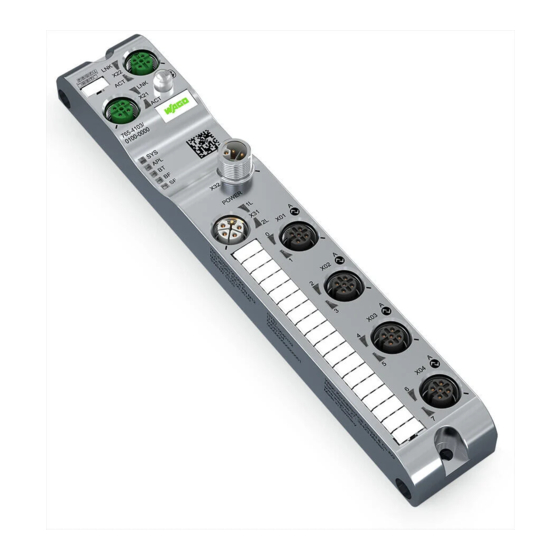
Properties 765-4203/0100-0000 Properties 4.1 View Figure 1: View Table 3: Legend for “View” Figure Function Position Custom Name Description ® ETHERNET ETHERNET interface, M12, D-coded, EtherCAT -IN port Product manual | Version: 1.0.0 4PORT IOL-A FLD EC DC 24V 2.0A... -
Page 15: Connections
765-4203/0100-0000 Properties Function Position Custom Name Description L/A (X21) Link/activity LED for port X21 LED with no function ® ETHERNET interface, M12, D-coded, EtherCAT port L/A (X22) Link/activity LED for port X22 LED with no function ® ® ® Bluetooth... -
Page 16: Communication Interfaces
Properties 765-4203/0100-0000 Table 4: Supply voltage Supply Voltage In- Supply Voltage Signal Description Output 24 VDC supply voltage U for system and sensor/actuator 2L− Reference potential for 2L 1L− Reference potential for 1L 24 VDC auxiliary/control voltage U Functional ground M12, L-coded, plug,... -
Page 17: Circuit Diagram
765-4203/0100-0000 Properties 4.3 Circuit Diagram The following figure shows the schematic circuit diagram of the product. Figure 2: Circuit Diagram for Each Port 4.4 Technical data 4.4.1 Product Table 7: Product Property Value Item Number 0765-4203/0100-0000 Product function 4-Port-IO-Link Master Class A Product name (short) 4 PORT IOL-A FLD EC 24 VDC 2.0 A... -
Page 18: Connection Technology
Properties 765-4203/0100-0000 4.4.3 Connection Technology Table 9: Connection technology Property Value Power Connection PWR IN: M12 L-coded, 5-pin, plug PWR OUT: M12 L-coded, 5-pin, socket EtherCAT Connection 2 × M12, D-coded, socket, 4-pin IO-Link ports 4 × M12, A-coded, socket, 5-pin Tightening Torque M12: 1.0 Nm... -
Page 19: Power Supply
765-4203/0100-0000 Properties Property Value Output current, L1 Maximum: 4.0 A per channel per IEC 61131-2 Output current, L1 with IO-Link operating mode Maximum 1.0 A with conductor size AWG 22/0.34 mm and cable length of up to 20 m (per IO-Link specifica- tion) Maximum 4.0 A with increased conductor cross-sec- tion or reduced cable length (max. -
Page 20: Electrical Safety
Properties 765-4203/0100-0000 Parameters Value Conductor cross-section For UL-compliant use: 2.5 mm Reverse voltage protection 4.4.5 Electrical Safety Table 12: Electrical Safety Property Value Insulation resistance 60 VDC Test voltage 550 VAC RMS Min. creepage distance 0.7 mm Requirements • Use of PELV/SELV power supplies • When SELV power supplies are used: SELV power supplies with supply via the same network phase •... -
Page 21: Table 16 Opc Ua Server
765-4203/0100-0000 Properties Parameters Value Operation with 4 IO-Link 32 Is / 32 Os: 130 bytes Operation with 8 DIs: 2 bytes Operation with 8 DOs: 6 bytes Type Complex slave Features Emergency SYNC manager Supported protocols SDO server CoE (CANopen over EtherCAT) -
Page 22: Derating
The product provides measured values for temperature and current, which you can display with WAGO Webserver I/O Field or read out via OPC UA. The following figure shows the maximum permissible current (I) that can flow into the product as a function of the surrounding air temperature (T). - Page 23 Certificate number: R20-0936-01-TEC (Slimline) FCC ID: 2AKUE-SLIMLINE ISED Certificate number: 22322-SLIMLINE Note More information on approvals You can find detailed information on the approvals online at: ü www.wago.com/<item number> Product manual | Version: 1.0.0 4PORT IOL-A FLD EC DC 24V 2.0A...
-
Page 24: Functions
Functions 765-4203/0100-0000 Functions 5.1 Process Image ® EtherCAT uses process data objects (PDO) to transfer process data. Process data is ® ® transferred from the EtherCAT master to the EtherCAT slave with objects 0x1600, 0x1601 etc.; these data objects are called receive PDOs (RxPDOs). Process data is ®... -
Page 25: Table 20 Objects 0X1A0X: Assignment Of The Digital Input
765-4203/0100-0000 Functions Index Subindex Size Name Description The number of “Input bytes” corresponds to the length of the module used in slot “IO- Link Port X01” and can be 1, 2, 4, 8, 16 or 32 bytes. 0x6010.01 1 byte... -
Page 26: Table 21 Object 0X1A10: Assignment Of The Digital Inputs
Functions 765-4203/0100-0000 Table 21: Object 0x1A10: Assignment of the Digital Inputs Index Subindex Size Name Description 0x3000.01 2 bytes PD (I/Q Pin 2 + C/Q The port and pin assignment of process Pin 4) data depends on the process data layout setting: pin-based or port-based. -
Page 27: Table 25 Object 0X1A80: Assignment Of The Io-Link Port Status
765-4203/0100-0000 Functions Table 25: Object 0x1A80: assignment of the IO-Link port status Index Subindex Size Name Description 0x1F00.01 1 byte State of IO-Link port Bit 0...3 IO-Link status 0: Port inactive 0x1F00.02 1 byte State of IO-Link port 1: SIO mode digital input... -
Page 28: Table 27 Objects 0X160X: Assignment Of The Digital Output
Functions 765-4203/0100-0000 Index Subindex Size Name Description The number of “Output bytes” corresponds to the length of the module used in slot “IO- Link Port X02” and can be 1, 2, 4, 8, 16 or 32 bytes. 0x7030.01 1 byte... -
Page 29: Forcing
The “Forcing” function can be accessed through the following tools: • WAGO I/O Field Webserver • WAGO I/O Field app on mobile devices Systems like SPS, TIA Portal and the like also have forcing functions. Such forcing func- tions should not be confused with the ones described in this section and will not be con- sidered within the context of this section. -
Page 30: Monitoring Functions
The measurements are performed for the module and for pin 1, pin 2 and pin 4 of each port. The measured values can be displayed in the WAGO I/O Field Webserver or the WAGO I/O Field app. Alternatively, an OPC UA client can read out the measured values and display them. -
Page 31: Parameterization Tools
Series module. Using a Web browser, the user can view the Web pages and dis- play and modify parameters. WAGO I/O Field App The WAGO I/O Field app is an app for mobile devices that can communicate with ® a 765 module via Bluetooth . -
Page 32: Wago Io-Link Configurator
I/O Field Webserver, the WAGO I/O Field app, the WAGO IO-Link Configurator or the OPC UA client are overwritten. If you have changed parameters of the port configuration via the WAGO I/O Field Web- server, the WAGO I/O Field app, the WAGO IO-Link Configurator or the OPC UA Client, ®... -
Page 33: Wago Webserver I/O Field
The WAGO IO-Link Configurator software can be launched as a stand-alone program from the Start menu or with the desktop icon, or in connection with WAGO I/O-CHECK. It then provides the functions necessary for connecting to WAGO IO-Link masters or searching for them. -
Page 34: Wago I/O Field App
Sign-out 5.5.4 WAGO I/O Field app The WAGO I/O Field app is an app for maintenance, diagnostics, operation and monitor- ing of installed WAGO I/O System Field modules and IO-Link devices. This app allows you to display product information, read and write process data and ad- just settings and parameters for both fieldbus modules and IO-Link devices. -
Page 35: Communication Interfaces
You can find Product-specific information on the WAGO App I/O Field in the online help for the app. An iOS version of the WAGO I/O Field app is available for free in the Apple App Store, and an Android version in the Google Play Store. - Page 36 Functions 765-4203/0100-0000 • Read measured values: current, voltage, temperature • Events: overcurrent, overload and overtemperature • Read status information • Read process data • Read statistics: minimum/maximum current per pin, minimum/maximum voltage per pin, minimum/maximum temperature • User access: anonymous (only read access) or username/password (read and write access) Product manual | Version: 1.0.0...
-
Page 37: Planning
• Do not connect control components and control networks to an open network such as the Internet or an office network. WAGO recommends protecting control components and control networks against unauthorized outside access by using a firewall. • Limit physical and electronic access to all automation components to authorized per- sonnel only. -
Page 38: Power Supply Concept
Planning 765-4203/0100-0000 6.2 Power Supply Concept 6.2.1 Design Power Supply NOTICE Device damage if permissible current feedthrough exceeded There is a risk of damage to the device and/or other devices connected to it if the maxi- mum permissible current feedthrough is exceeded. - Page 39 765-4203/0100-0000 Planning – Rule 1: Take maximum load capacity of each connection contact (pin) into ac- count – Rule 2: Take 1L and 2L current feedthrough into account • Ports X01, X02 etc. – Rule 3: The current load of pin 3 must not exceed 4 A, since the sum of the pin 1, 2 and 4 currents flows back through pin 3.
-
Page 40: Table 35 Upper Limits For Current On The Individual Pins Of The Connections
Planning 765-4203/0100-0000 termined by the current load capacity of the pluggable connector on the input supply con- nection and the PCB. This is max. 16 A. The total current must not exceed this current load capacity. Note the following: 1. When using digital outputs, the current feedthrough must be reduced by the current that flows through these outputs, for example. -
Page 41: Requirements On The Power Supply
765-4203/0100-0000 Planning Current Description Total current for supply cable 1 on port X0i (i.e. port X01, X02, ... , X04); X01_1L corresponds to the current I on pin 3 (ground). This current is the X02_1L … , X04_1L X0i_pin3_1L sum of the currents on pins 1, 2 and 4 of port X0i:... -
Page 42: Additional Measures
Planning 765-4203/0100-0000 Note Note the following when L1 and L2 are supplied separately: If L1 and L2 are to be supplied separately (e.g., for safe switch-off of L2), then either cen- tral grounding must be implemented using two power supply units, or the power supply connection must be made on the same phase. - Page 43 16 A – 4.2 A = 11.8 A for supply cable 1 (1L) und 16 A – 4.0 A = 12 A for supply ca- ble 2 (2L). Example of Individual Power Supply This example considers a single 765-4203/0100-0000 module where no additional de- vices are powered through its PWR OUT connection (X32). Figure 4: Connection Example for 765-4203/0100-0000 Module with Individual Power Supply One IO-Link class A device with max.
- Page 44 Example of a Power Supply Group with an IO-Link Hub Connection Example 1 In what follows, we consider a power supply group consisting of a 765-4203/0100-0000 IO-Link Master and a 765-1701/0200-0000 IO-Link Hub. The two products are connected via IO-Link.
-
Page 45: Settings Options
Figure 6: Power Supply Group with 765-4203/0100-0000 – Connection Example 2 To do so, we consider port X01 of the 765-4203/0100-0000 module: This has a load of 5.2 A = 2 A + 2 A + 0.5 A + 0.5 A + 0.2 A on pin 1. This exceeds the maximum load capacity of 4 A and it thus not permitted. -
Page 46: Table 40 Port Parameters
0: Activation of BT in- The Bluetooth interface can be en- terface is allowed abled by an optical signal of a mobile device and in connection with the WAGO I/O Field app. ® 1: Disable activation of The Bluetooth interface cannot be BT interface... -
Page 47: Table 41 Io-Link Port Parameters
765-4203/0100-0000 Planning Index Subindex Parametername Value Range Default Description time the signal must be present in or- der for a signal change to be de- tected. 0x2100.03, Port X01/X02/… 0 (OFF) Pin 4 is a digital output. 0x2110.03, … 1: On Pin 4 is a digital output and switched... -
Page 48: Table 42 Calculation Of Port Cycle Time
Planning 765-4203/0100-0000 Index Subindex Parametername Value Range Default Description 0x8000.20, IO-Link port X01/ 0, 16, 17 Check of the IO-Link version: X02/... 0x8010.20, 0: no check IO-Link Revision 16: checking whether the connected IO-Link supports specification V1.0. 17: checking whether the connected IO-Link supports specification V1.1. - Page 49 765-4203/0100-0000 Planning Value Range Time Basis (Bits Factor (Bits 0–5) Port Cycle Time Examples 6+7) (Formula) 32: 3.2 ms 48: 4.8 ms 64 ... 127 0.4 ms (01) 0 ... 63 6.4 ms + 0.4 ms * 68: 8.0 μs factor 93: 18.0 ms 100: 20.8 ms 128 ... 191 1.6 ms (10) 0 ... 63 32 ms + 1.6 ms * fac- 133: 40.0 μs...
-
Page 50: Transport And Storage
Transport and Storage 765-4203/0100-0000 Transport and Storage The original packaging offers optimal protection during transport and storage. • Store the product in suitable packaging, preferably the original packaging. • Only transport the product in suitable containers/packaging. • Make sure the product contacts are not contaminated or damaged during packing or unpacking. -
Page 51: Installation And Removal
765-4203/0100-0000 Installation and Removal Installation and Removal 8.1 Installation 8.1.1 Tools Required for Installation The following tools are required for installation: • Allen wrench for the M4 hex head mounting screws The following additional items are only required for installation where no threaded hole is present: •... -
Page 52: Note On Protecting Against Heat Generation By The Product
Installation and Removal 765-4203/0100-0000 • When mounting, be sure not to contaminate the connections. The contamination dam- ages the contacts, which can limit the reliability of the contacts. 8.1.4 Note on Protecting against Heat Generation by the Product During operation, the product can get hot! Therefore, always note the following informa- tion: •... -
Page 53: Removal
765-4203/0100-0000 Installation and Removal • Grounding can be done separately via a cable lug and the mounting hole if the module is installed on a non-conductive subsurface Ensure proper contacts and a sufficient cable cross-section. 8.2 Removal 8.2.1 Tools Required for Removal For removal, you need an Allen key to unscrew the M4 cylinder head hex screws per DIN 912/ISO 4762. -
Page 54: Connection
Connection 765-4203/0100-0000 Connection 9.1 General Information on Installation When laying cables, the local conditions and the applicable regulations are crucial for im- plementation. Be sure to maintain the minimum clearances between the cabling and possible sources of interference (including machines, welding equipment and power lines) to prevent loss and corruption of data. - Page 55 Note that the connection for the additional supply voltage is not monitored for overload. If the maximum current carrying capacity is exceeded, this can damage the pluggable con- nectors. WAGO recommends using pre-assembled cables. The following figure gives an example of feeding in and passing on the supply voltages: Product manual | Version: 1.0.0...
- Page 56 Connection 765-4203/0100-0000 Figure 7: Example of Feeding in and Passing on the Supply Voltages In connection with this figure, note that the cables illustrated for current paths 1L and 2L are realized not as separate cables, but rather as separate wires within one common ca- ble.
-
Page 57: Connecting Cables
Cable cross-section 9.3 Connecting Cables WAGO recommends using 765 Series connecting cables, pluggable connectors and ac- cessories for 756 Series products, which have been tailored specifically to the WAGO I/O System Field. 8 Connection Technology [} 18] The tightening torques given in section apply to the pluggable connectors of the connecting cables. - Page 58 3. Tighten the pluggable connector using the knurled-head screw. Connecting Multiple Products to One ETHERNET Network The fieldbus module of the WAGO I/O System Field has two connections, IN and OUT, to allow wiring of a line topology. Multiple products can be connected to the ETHERNET network as shown in the following example: 1.
-
Page 59: Connect Sensors/Actuators
765-4203/0100-0000 Connection ® Figure 9: Line Topology for EtherCAT Networks (Module Image May Differ) 9.5 Connect Sensors/Actuators The sensor/actuator cable provides power to the connected sensors/actuators and trans- fers the sensor and actuator signals. 8 Design Power Note the current load capacity of the supply contacts; see “Rule 3” in Supply [} 38], section Rule 3: Ports X01, X02 etc. - Page 60 Connection 765-4203/0100-0000 Ethernet Ethernet PWR OUT PWR IN DIO B DIO B DIO B DIO B Figure 10: Schematic Circuit Diagram of the Power Supply The following table shows the connection options for IO-Link devices (class A) and digital inputs and outputs.
-
Page 61: Table 43 Connecting An Io-Link Device Or Digital Input Or Output
765-4203/0100-0000 Connection Table 43: Connecting an IO-Link Device or Digital Input or Output Connection Option Description Connection of an IO-Link device Required port configuration: IO-Link master and pin 2 disabled. Connection of an IO-Link device and a digital input on channel B. - Page 62 Connection 765-4203/0100-0000 Connection Option Description Connection of a digital output on channel A and a digital input on channel B. Required port configuration: pin 4 as a digital output and pin 2 as a digital in- put. Product manual | Version: 1.0.0...
-
Page 63: Commissioning
The module requires an IP address if IP-based communication is to be used. This is the case, for example, if the WAGO I/O Field Webserver or the OPC UA server of the module is used. The module has no IP address when delivered. The module gets the IP address ®... -
Page 64: Selecting The Module
Commissioning 765-4203/0100-0000 ð The IP address has been set. 10.2 Configuration 10.2.1 Configuring EtherCAT ® ® To configure the EtherCAT master, you need the ESI (EtherCAT Slave Information) files in XML format: WAGO_series765.xml and WAGO_series765_diag.xml The file WAGO_series765.xml contains a reference to the file WAGO_se- ries765_diag.xml, which contains diagnostic texts. -
Page 65: Setting Parameters
10.3.1 WAGO Webserver I/O Field 10.3.1.1 Call WAGO Webserver I/O Field This section describes how you can use the integrated software WAGO I/O Field Web- server to get access to detailed information on the current operating state of the product and make settings to affect the product’s behavior. -
Page 66: User Interface Of The Wago Webserver I/O Field
10.3.1.2 User Interface of the WAGO Webserver I/O Field Figure 12: Dashboard Menu Item, Main Page When the user interface of the WAGO I/O Field Webserver opens, the main page of the Dashboard appears first. It shows the following product information: Table 45: Data on the “Dashboard”... -
Page 67: Advanced Module And Port Information
• A list of the licensed software components the product contains • A link for each licensed software component to the associated license terms 10.3.1.3 Opening the Product Information via WAGO Webserver I/O Field 10.3.1.3.1 Displaying Port Information For each of the module’s IO-Link ports (port X01, port X02 etc.), individual port informa- tion can be found on the Information, Status, Configuration, IOL and Process data tabs. -
Page 68: Displaying Measured Values And Information On Connected Io-Link Devices
Commissioning 765-4203/0100-0000 10.3.1.3.2 Displaying Measured Values and Information on Connected IO-Link Devices Figure 13: Information Tab, Port XX Menu Item The Information tab shows the following information: • The measured values and states of the port diagnostics • The information on connected IO-Link devices... -
Page 69: Table 47 Additional Information On The Products Connected To The Selected Port
765-4203/0100-0000 Commissioning Displaying Information on Connected IO-Link Devices On IO-Link ports on which an IO-Link device is connected and recognized by the prod- uct’s firmware, the following product information is also displayed in the Device informa- tion block: Figure 14: Information Tab, Port XX Menu Item Table 47: Additional Information on the Products Connected to the Selected Port... -
Page 70: Displaying Port Status Information
Commissioning 765-4203/0100-0000 10.3.1.3.3 Displaying Port Status Information Figure 15: Port XX Menu Item, Status Tab The Status tab shows status information for pins 2 and 4 of the selected port. This tab answers the following questions about the selected port: • What is the current port status of the port? •... -
Page 71: Quality
765-4203/0100-0000 Commissioning Value Port Status Description Incorrect Device The version or compatibility check failed Preoperate The product is ready for communi- cation Operate The product is communicating DI CQ The port is in digital input mode DO CQ The port is in digital output mode... -
Page 72: Input Data Length
Commissioning 765-4203/0100-0000 Table 50: Cycle Time of the Master – Bits 6 ... 7 Bits 6 ... 7 Calculation Formula Multiplier × 0.1 ms 6.4 ms + multiplier × 0.4 ms 32.0 ms + multiplier × 1.6 ms Reserved 10.3.1.3.9 Input Data Length This shows the actual input data length of the connected product in bytes. -
Page 73: Parameterizing The Module Via The Wago I/O Field Webserver
765-4203/0100-0000 Commissioning 10.3.1.4 Parameterizing the Module via the WAGO I/O Field Webserver You can make the following settings on the module with WAGO Webserver I/O Field: 8 Accessing a Connected IO-Link Device [} 77] • 8 Configuring Ports [} 73] • 8 Configuring IP Parameters [} 80] •... -
Page 74: Table 52 "Port Mode" Drop-Down Menu: Selecting The Operating Mode For Pin 4 Of The Selected Io-Link Port
Commissioning 765-4203/0100-0000 Name Type Description VendorID Input field Expected manufacturer ID of the connected device DeviceID Input field Expected device ID of the connected device The Validation and Backup, PortCycleTime, VendorID and DeviceID settings only ap- pear for the IOL Manual selection in the Port mode (pin 4) drop-down menu. -
Page 75: Table 53 Iq Behavior Drop-Down Menu - Configuration Of Pin 2 (I/Q) For Io-Link Class A De- Vices
765-4203/0100-0000 Commissioning Setting the Filter Time for Digital Inputs The filter time for the digital inputs can be selected from the Digital input signal filter drop-down menu. You can select from the following values: • No digital input filter • 3 ms •... -
Page 76: Table 55 Possible Values Of The Backup Level Parameter
Commissioning 765-4203/0100-0000 The Backup Level parameter determines the system behavior when a device connected to the port is replaced in terms of continued operation with unmodified device parameters. This parameter can have three different values: Table 55: Possible Values of the Backup Level Parameter... -
Page 77: Accessing A Connected Io-Link Device
765-4203/0100-0000 Commissioning 10.3.1.4.2 Accessing a Connected IO-Link Device The IOL tab allows read and write access to the IO-Link device connected to an IO-Link port via index and subindex. The ISDU message format (ISDU = Indexed Service Data Unit) is used for this purpose. - Page 78 Commissioning 765-4203/0100-0000 2. On the IOL tab, enter the subindex of the connected IO-Link device you want to ac- cess into the Subindex field as a hexadecimal value; the default setting is 00 3. Click the [Read] button. ð The read operation is performed. An entry is written to the history at the bottom of the tab and logged there with the current time.
- Page 79 765-4203/0100-0000 Commissioning 1. On the IOL tab, enter the index of the connected IO-Link device you want to access into the Index field as a hexadecimal value. 2. On the IOL tab, enter the subindex of the connected IO-Link device you want to ac- cess into the Subindex field as a hexadecimal value;...
-
Page 80: Configuring Ip Parameters
Commissioning 765-4203/0100-0000 10.3.1.4.3 Configuring IP Parameters Figure 20: Settings Menu Item, Device Configuration Tab ® ® The EtherCAT master configures the module’s IP address. Therefore, with EtherCAT modules, no manual IP address configuration is necessary. 10.3.1.4.4 Storing Maintenance Information On the Maintenance Information tab, you can store maintenance information, such as the device name, the installation location and date, contact information, a description text or the date of the last and next product service. -
Page 81: Table 57 Maintenance Information
765-4203/0100-0000 Commissioning Figure 21: Settings Menu Item, Maintenance Information Tab Changes to settings require operator or admin rights. If you do not have these, the Main- tenance Information tab is grayed out and cannot be edited. The maintenance information includes: Table 57: Maintenance Information... -
Page 82: Updating Firmware
3. Modify the relevant fields there. 4. Click the [Apply] button. ð Your changes take effect. 10.3.1.4.5 Updating Firmware With the Firmware upgrade tab, WAGO Webserver I/O Field provides an option for up- dating the product firmware. Figure 22: Settings Menu Item, Firmware Upgrade Tab NOTICE... -
Page 83: Resetsetting The Module To The Factory Settings
To update the firmware, you need a firmware container file: FWUPDATE.ZIP. You can get it from the Downloads section of the WAGO website: ü http://www.wago.com. Proceed as follows to update the firmware: 1. In the left-hand column of the WAGO I/O Field Webserver, click the Settings menu item. ð The Device configuration tab appears. -
Page 84: Configure Bluetooth
Reset All All Settings To reset the module to the factory settings, proceed as follows: 1. In the left-hand column of the WAGO I/O Field Webserver, click the Settings menu item. ð The Device configuration tab appears. 2. Select the Factory reset tab. - Page 85 • Switching the Bluetooth wireless connection on/off ® • Switching the Bluetooth LED on/off ® Proceed as follows to access these Bluetooth functions in the WAGO I/O Field Web- server: ® • Open the Bluetooth tab. ® ð The Bluetooth tab appears.
-
Page 86: Table 59 Status Of The Last Bluetooth® Firmware Update
® To enable the Bluetooth interface, you must have the WAGO I/O Field app installed on the smartphone or tablet. Proceed as follows: ® • A DM code appears in the “Information” section of the Bluetooth tab. -
Page 87: Logging Users On And Off And Managing Them
765-4203/0100-0000 Commissioning ® Switching the Bluetooth Interface Wireless Transmitter on/off ® To switch the Bluetooth interface wireless transmitter on: • Slide the Bluetooth radio switch to the right ð The Bluetooth ® interface wireless transmitter switches on. ® To switch the Bluetooth interface wireless transmitter off, slide the Bluetooth radio switch to the left. - Page 88 Commissioning 765-4203/0100-0000 ð If you have entered a known username correctly, you can now work with the WAGO I/ O Field Webserver with this user’s specified rights. The username that was used to log on is shown in the upper left-hand corner. The Sign in menu item changes to Sign out.
- Page 89 765-4203/0100-0000 Commissioning Figure 26: User Administration Menu Item (Initial State) The user root with pre-set password password exists by default; see first row. An additional user can be created in the second row. Proceed as follows: 1. In the Username field, enter the username to use for the user. Users that are al- ready in use are not allowed here.
-
Page 90: Forcing Digital Inputs And Outputs
Commissioning 765-4203/0100-0000 ð The new user is created and assigned the selected role. Removing Users To remove an existing user from the product’s user administration, proceed as follows: • Click the red square with the white “x” to the right of the user you want to remove. -
Page 91: Forcing For Io-Link Ports
As long as one user is accessing the forcing functionality through a forcing medium, e.g., the WAGO I/O Field Webserver, it is locked for all other users of the module. They cannot access the forcing functionality until the user that is active now terminates his or her ac- cess. - Page 92 As long as one user is accessing the forcing functionality through a forcing medium, e.g., the WAGO I/O Field Webserver, it is locked for all other users of the module. They cannot access the forcing functionality until the user that is active now terminates his or her ac- cess.
-
Page 93: Wago Io-Link Configurator
10.3.3.1 Parameterizing a Module with the WAGO I/O Field App Note Read the online help! You can find Product-specific information on the WAGO App I/O Field in the online help for the app. 10.3.4 OPC UA Server The device contains an OPC UA server. An OPC UA client can establish a connection wot the device and access the following parameters, among others: •... -
Page 94: Parameterizing The Product Via Opc Ua
Commissioning 765-4203/0100-0000 Figure 30: OPC UA: Device Information Model 10.3.4.1 Parameterizing the Product via OPC UA 10.3.4.1.1 Identifying Devices The device provides nodes for device identification. For example, the OPC UA client can read out the version of the device firmware used in the SoftwareRevision node. The path to this node is: Root >... -
Page 95: Configuring Parameters
765-4203/0100-0000 Commissioning 10.3.4.1.2 Configuring Parameters The OPC UA server provides nodes with configuration parameters for the device. For ex- ample, the OPC UA client can read out the upper limiting value for temperature in the OverTemperature node. The path to this node is: Root >... -
Page 96: Reading Out Measured Values
Commissioning 765-4203/0100-0000 10.3.4.1.3 Reading out Measured Values The OPC UA server provides nodes with calculated measured values. For example, the OPC UA client can read out the calculated total current of supply cable 1 in the SumCur- rentL node. The path to this node is: Root >... -
Page 97: Reading Statistics
765-4203/0100-0000 Commissioning Table 66: Port-Specific Diagnostics Node Name Node Class Access Description DiagnosticsPin1, Di- Variable Read Diagnostics on pin 1, pin 2 or pin 4; the nu- agnosticsPin2, Diag- merical value contains bit-coded informa- nosticsPin4 tion: Bit 0: short circuit Bit 1: overload protection... - Page 98 Commissioning 765-4203/0100-0000 Node Name Node Class Access Description MinVoltagePin1, Variable Read Minimum voltage on pin 1, pin 2 or pin 4 MinVoltagePin2, since the value was reset; unit: mV MinVoltagePin4 Product manual | Version: 1.0.0 4PORT IOL-A FLD EC DC 24V 2.0A...
-
Page 99: Diagnostics
765-4203/0100-0000 Diagnostics Diagnostics 11.1 Diagnostics via Indicators Power Supply Status The 1L and 2L LEDs indicate the status of the supply voltages. Table 68: Supply Voltage Status, 1L and 2L Color State Description Duo LED, red/green Green 1L supply voltage OK 1L undervoltage (voltage between 11 V and... -
Page 100: Table 72 Ethercat® Slave Status
Diagnostics 765-4203/0100-0000 ® EtherCAT Slave Status ® The following table describes the LED states of the EtherCAT slave. ® Table 72: EtherCAT Slave Status Color State Description Duo LED, red/green INT: The module is in state INIT. Green Flashing (2.5 Hz) PRE-OPERATIONAL: The module is in state PREOPERATIONAL. -
Page 101: Table 75 Led States Ethernet Status
765-4203/0100-0000 Diagnostics Color State Description The module is not connected to the ETH- ERNET. – LED yellow This LED is not used. Table 75: LED States ETHERNET Status LED State Definition Flickering The indicator switches on and off at a frequency of 10 Hz, indicating high ETHERNET... -
Page 102: Diagnostics Via Ethercat
Diagnostics 765-4203/0100-0000 11.2 Diagnostics via EtherCAT 11.2.1 Diagnostic History Table 78: Diagnostic History (Index 0x10F3) Subindex Name Explanation Type Flags Default Highest supported Highest supported subindex UINT8 subindex see . Maximum Messages Number of diagnostic messages that can UINT8 be stored in the diagnostic history See . -
Page 103: Subindex 4: New Messages Available
765-4203/0100-0000 Diagnostics Writing = 0: If a value of 0 is written to subindex 3, the EtherCAT slave deletes subindex 2, subindex 3, subindex 4 and subindex 5 bit 5 or sets them to 0. Diagnostic messages are deleted even if they have not been acknowledged or read yet. -
Page 104: Subindex 5: Flags
Diagnostics 765-4203/0100-0000 Overwrite Mode 0: The newest message has been read. 1: The newest message has not been read. Acknowledgment Mode 0: No unacknowledged diagnostic message present 1: There are diagnostic messages that can be acknowledged. 11.2.1.6 Subindex 5: Flags The subindex contains flags for controlling the sending and saving of diagnostic mes- sages. -
Page 105: Structure Of A Diagnostic Message
765-4203/0100-0000 Diagnostics 11.2.1.8 Structure of a Diagnostic Message A diagnostic message in subindexes 6 to 69 has the following structure: Table 80: Structure of a Diagnostic Message in Subindexes 6 to 69: Parame- Datatype Description ters Diag UINT32 Diagnostic code for identifying the diagnostic message Code Bits 0–15 =... -
Page 106: Emergency Error Codes
Diagnostics 765-4203/0100-0000 Parame- Datatype Description ters Parame- UINT16 Describes the type of parameter 3 ter 3 Bits 12–15 = 0 Bits 0–11 = data type index of the data type of parameter 3 Flags 0x0005: UINT8 The corresponding text parameters and formatting are de- scribed in document ETG.2000. -
Page 107: Table 83 General Alarms
765-4203/0100-0000 Diagnostics Emergency Error Code (hex) Description 62xx User Softwares 63xx Data Set 70xx Additional Module 80xx Monitoring 81xx Communication 8110 CAN Overrun (Objects lost) 8120 CAN in Error Passive Mode 8130 Life Guard Error or Heartbeat Error 8140 recovered from bus off... -
Page 108: Events Triggered By The Io-Link Master
Diagnostics 765-4203/0100-0000 Emergency Alarm Description Remedy Error Code (hex) 0xFF08 Forcing operat- Forcing operating mode active (activated by The Web client or OPC UA ing mode active Web client or OPC UA client) client should exit the Forcing op- erating mode as soon as forcing is no longer needed. -
Page 109: Events Triggered By The Io-Link Device
765-4203/0100-0000 Diagnostics IO-Link Event Code Description Remedy 0x6001 Revision error (incompatible protocol Check port configuration parameters version) 0x6002 ISDU batch failed Fix parameter inconsistency 11.2.1.11 Events Triggered by the IO-Link Device Events can also be triggered by an IO-Link device connected to the IO-Link master via a port. -
Page 110: Diagnostic Data Of The Modules
Diagnostics 765-4203/0100-0000 IO-Link Event Code Description of the Error Function Corrective Action on the Connected on the Connected IO-Link Device IO-Link Device 0x8C20 Measurement overrange Check application 0x8C30 Process variable value below value Process data insecure range 0x8C40 Maintenance required... -
Page 111: Service
Service Service 12.1 Resetting to Factory Settings The device can be reset to the factory settings. Use the WAGO I/O Field Webserver for this purpose. You can find information on the procedure under Parameterizing the Module via the 8 Resetsetting the Module to the Factory Settings WAGO I/O Field Webserver >... -
Page 112: Decommissioning
Decommissioning 765-4203/0100-0000 Decommissioning 13.1 Entsorgung und Recycling Table 88: WEEE Mark Logo Description Electrical and electronic equipment may not be disposed of with household waste. This also applies to products without this mark. Electrical and electronic equipment contain materials and substances that can be harmful to the environment and health. -
Page 113: Appendix
EU Declaration of Conformity Hereby, WAGO Kontakttechnik GmbH & Co. KG declares that the radio equipment type 0765-4203/0100-0000 is in compliance with Directive 2014/53/EU. The full text of the EU declaration of conformity is available at the following internet address: ü www.wago.com... -
Page 114: Operational Description
Appendix 765-4203/0100-0000 Changes or modifications made to this equipment not expressly approved by WAGO Kontakttechnik GmbH & Co. KG may void the FCC authorization to operate this equip- ment. 14.2 Operational Description Product description The product 0765-4203/0100-0000 is used to capture field signals on sensors, actuators and hubs which have been sent or received by a higher-level controller and output them via IO-Link. -
Page 115: Protected Rights
765-4203/0100-0000 Appendix We declare that we meet the EN 62479 standard with respect to the limiting value for low powers less than 20 mW. Therefore, the product fundamentally corresponds to the Euro- pean limiting values for high-frequency radiation. Product Designs SlimLine (W × H × D) 35 ×... - Page 116 Appendix 765-4203/0100-0000 ® • Modbus is a registered trademark of Schneider Electric, licensed for Modbus Organi- zation, Inc. • OPC UA is a registered trademark of the OPC Foundation. ® • PROFIBUS is a registered trademark of the PROFIBUS Nutzerorganisation e.V.
- Page 117 Overview of Parameterization Tools .................. Table 32 Parameterization Overview....................Table 33 Function Overview for WAGO I/O Field Webserver and WAGO IO-Link Modules .... Table 34 Additional documentation....................Table 35 Upper Limits for Current on the Individual Pins of the Connections ........
- Page 118 List of Tables 765-4203/0100-0000 Table 37 Module 0765-4203/0100-0000 – Currents in Supply Cable 2..........Table 38 Rules for Supply Cables 1 and 2 ..................Table 39 Module Parameters......................Table 40 Port Parameters......................... Table 41 IO-Link Port Parameters ....................Table 42 Calculation of Port Cycle Time...................
- Page 119 765-4203/0100-0000 List of Tables Table 73 LED States of EtherCAT® slave ..................100 Table 74 ETHERNET Status ......................100 Table 75 LED States ETHERNET Status ..................101 Table 76 LED States ® ........................101 Table 77 IO-Link Port Status (Class A)..................... 101 Table 78 Diagnostic History (Index 0x10F3)..................
- Page 120 Derating, 0765-4203/0100-0000 ................... Figure 4 Connection Example for 765-4203/0100-0000 Module with Individual Power Supply.. Figure 5 Power Supply Group with 765-4203/0100-0000 – Connection Example 1 ....Figure 6 Power Supply Group with 765-4203/0100-0000 – Connection Example 2 ....Figure 7 Example of Feeding in and Passing on the Supply Voltages ........
- Page 121 765-4203/0100-0000 List of Figures Product manual | Version: 1.0.0 4PORT IOL-A FLD EC DC 24V 2.0A...
- Page 122 WAGO is a registered trademark of WAGO Verwaltungsgesellschaft mbH. Copyright – WAGO Kontakttechnik GmbH & Co. KG – All rights reserved. The content and structure of the WAGO websites, catalogs, videos and other WAGO media are subject to copyright. Distribution or modification of the contents of these pages and videos is prohibited. Furthermore, the content may neither be copied nor made available to third parties for...
Need help?
Do you have a question about the 765-4203/0100-0000 and is the answer not in the manual?
Questions and answers