Table of Contents

Subscribe to Our Youtube Channel
Related Manuals for WAGO 750 Series


Summary of Contents for WAGO 750 Series
- Page 1 Fieldbus Independent I/O Modules EnOcean Radio Receiver 750-642 Manual Version 1.1.0...
- Page 2 • General Copyright 2011 by WAGO Kontakttechnik GmbH & Co. KG All rights reserved. WAGO Kontakttechnik GmbH & Co. KG Hansastraße 27 D-32423 Minden Phone: +49 (0) 571/8 87 – 0 Fax: +49 (0) 571/8 87 – 1 69 E-Mail: info@wago.com...
-
Page 3: Table Of Contents
Copyright ..................... 4 1.1.2 Personnel Qualifications..............4 1.1.3 Use of the 750 Series in Compliance with Underlying Provisions ..5 1.1.4 Technical Condition of Specified Devices .......... 5 Standards and Guidelines for Operating the 750 Series......6 Symbols ....................7 Safety Information.................. -
Page 4: Important Notes
Co. KG, Minden, Germany. Non-observance will involve the right to assert damage claims. WAGO Kontakttechnik GmbH & Co. KG reserves the right to provide for any alterations or modifications that serve to increase the efficiency of technical progress. WAGO Kontakttechnik GmbH & Co. KG owns all rights arising from the granting of patents or from the legal protection of utility patents. -
Page 5: Use Of The 750 Series In Compliance With Underlying Provisions
View All responsible persons have to familiarize themselves with the underlying legal standards to be applied. WAGO Kontakttechnik GmbH & Co. KG does not assume any liability whatsoever resulting from improper handling and damage incurred to both WAGO´s own and third-party products by disregarding detailed information in this Manual. -
Page 6: Standards And Guidelines For Operating The 750 Series
The equipment of your system shall be conform to EMC guidelines so that any electromagnetic interferences will be eliminated. Operating 750 Series components in home applications without further measures is permitted only if they meet the emission limits (emissions of interference) in compliance with EN 61000-6-3. -
Page 7: Symbols
Observe the precautionary measure for handling components at risk of electrostatic discharge. Note Make important notes that are to be complied with so that a trouble-free and efficient device operation can be guaranteed. Additional Information References to additional literature, manuals, data sheets and internet pages. WAGO-I/O-SYSTEM 750 I/O Modules... -
Page 8: Safety Information
Danger The WAGO-I/O-SYSTEM 750 and its components are an open system. It must only be assembled in housings, cabinets or in electrical operation rooms. Access is only permitted via a key or tool to authorized qualified personnel. -
Page 9: Font Conventions
(.) 1.7 Scope This manual describes the Special Module 750-642 EnOcean Radio Receiver of the modular WAGO-I/O-SYSTEM 750. Handling, assembly and start-up are described in the manual of the Fieldbus Coupler/Controller. Therefore this documentation is valid only in the connection with the appropriate manual. -
Page 10: O Modules
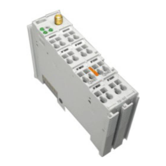
Accessories required: WAGO RF-ANTENNA 868MHz/SMA, Item-No.: 758-910 (not included in delivery)! Attention Use excluding the recommended WAGO RF-ANTENNA 868MHz/SMA (Item-No.: 758-910). Only these antennas can guarantee the technical characteristics and that the EMC and the R&TTE guideline are kept. 2.1.1.1 View Fig. -
Page 11: Description
The module receives the radio transmitter data via an antenna with a carrier frequency of 868.3 MHz situated outside the enclosure. For this an antenna equipped with an SMA plug (WAGO RF ANTENNA 868 MHz/SMA, Item-no.: 758-910) is connecting to the SMA socket fitted to the module. - Page 12 IF and PRIO plug-ins. The module is directly supported by the controllers of the WAGO-I/O-SYSTEM 750. Where a coupler is used, the use of a primary controller is necessary for control of the module. This module can be used with all couplers/controllers of the WAGO-I/O-SYSTEM 750 (except for the economy types 750-320, -323, -324 and -327).
- Page 13 750-642 [EnOcean Radio Receiver] • 13 Description Fig. 2.1.1-2: Operating principle of the EnOcean Radio Receiver module g064217e WAGO-I/O-SYSTEM 750 I/O Modules...
-
Page 14: Display Elements
Elements time of persistence 0.5 sec. g064229x no signal transmission RxD green Signal transmission RxD 2.1.1.4 Schematic Diagram Antenna Antenna socket (SMA) Radio Logic module RSSI Function RSSI 750-642 Fig. 2.1.1-4: Schematic Diagram g064201e WAGO-I/O-SYSTEM 750 I/O Modules... -
Page 15: Technical Data
EN 61000-6-2 (2005) (CE) EMC-Emission of interference acc. to EN 61000-6-3 (2007) (CE) EMC-Immunity to interference acc. to Germanischer Lloyd (2003) * (Ship building) EMC-Emission of interference acc. to Germanischer Lloyd (2003) * (Ship building) WAGO-I/O-SYSTEM 750 I/O Modules... -
Page 16: Process Data
(in exactly the same way as the WAGO RS 232 interface module, part no.: 750-650). Up to 3 input bytes are employed for transfer of the received data. Since the transmit channel of the interface is not used, the 3 bytes for output data are unused. -
Page 17: For Pfc Application
Further function blocks then interpret and process the message content. Further Information The function blocks for WAGO-I/O-PRO can be downloaded free of charge from the Internet. These can be found at: www.wago.com Service Downloads Building automation ... -
Page 18: For Coupler Application With Primary Controller
RS 232 C serial interface (item-no. 750-650). This is available on the Internet at: http://www.wago.com Attention In opposite to the description in the manual for the RS 232 C serial interface (item-no. 750-650) the bit sequence of the status byte changed! WAGO-I/O-SYSTEM 750 I/O Modules... - Page 19 1 Byte data telegram from a Solar Transmitter Module (STM) received 4 Byte data telegram from a Solar Transmitter Module (STM) received Telegram from a solar supplied hand remote control (CTM) received (Hand Remote Control) 0-4, 9-255 Reserved WAGO-I/O-SYSTEM 750 I/O Modules...
- Page 20 N-message and releasing the rocker sends an U-message. b) if ORG = 6, 7 or 8 (all other telegrams): Bit 7 Bit 0 Reserved RP_COUNTER Reserved (4 bit) for future use RP_COUNTER (4 bit) Repeater level: 0 is original message (not repeated) WAGO-I/O-SYSTEM 750 I/O Modules...
- Page 21 DATA_BYTE3 Value of third sensor analog input DATA_BYTE2 Value of second sensor analog input DATA_BYTE1 Value of first sensor analog input DATA_BYTE0 Sensor digital inputs as follows: Bit 7 Bit 0 Reserved DI_3 DI_2 DI_1 DI_0 WAGO-I/O-SYSTEM 750 I/O Modules...
-
Page 22: Notes On Application
Avoid installing the module, the antenna and the antenna line close to sources of transient interferences, such as fluorescent tubes with defective starter, frequency converters and power cables. As a result, communication failures may occur leading to faulty digital and analog values. WAGO-I/O-SYSTEM 750 I/O Modules... - Page 23 Attention Order the WAGO RF-ANTENNA 868MHz/SMA separately as accessories under the Item-No.: 758-910. The WAGO RF-ANTENNA 868MHz/SMA is not included in delivery of the radio receiver module! 2) The antenna is to be mounted on a plate measuring at least 9.8 x 9.8 inches (25 x 25 cm).
- Page 24 Fresnel ellipsoid c = semi-minor axis c = 1,6 d = distance in km = wave length in cm Fig. 2.1.1-6: Fresnel zone g064219e WAGO-I/O-SYSTEM 750 I/O Modules...
-
Page 25: Installation In Case Of Mechanical Stress (Vibration, Shock)
53 to 130 bits depending on sensor type (32-bit sensor ID no., up to 4 bytes sensor data, checksum) Transmission time around 40 ms for three identical telegrams, each around 1 ms and delayed at random WAGO-I/O-SYSTEM 750 I/O Modules... -
Page 26: Further Performance Features
Integrated power flux densities in the frequency range 100 MHz to 3.0 GHz: Device/system Integrated power flux density [W/m²] Radio switch 1,3*10 Conventional switch 1,5*10 In addition, the low frequency electrosmog is clearly reduced due to significantly fewer power cables in the building. WAGO-I/O-SYSTEM 750 I/O Modules... -
Page 27: Ec Certificate Of Conformity
750-642 [EnOcean Radio Receiver] • 27 EC Certificate of Conformity 2.1.1.12 EC Certificate of Conformity 2.1.1.12.1 English WAGO-I/O-SYSTEM 750 I/O Modules... -
Page 28: German
28 • 750-642 [EnOcean Radio Receiver] EC Certificate of Conformity 2.1.1.12.2 German WAGO-I/O-SYSTEM 750 I/O Modules... -
Page 29: French
750-642 [EnOcean Radio Receiver] • 29 EC Certificate of Conformity 2.1.1.12.3 French WAGO-I/O-SYSTEM 750 I/O Modules... - Page 30 WAGO Kontakttechnik GmbH & Co. KG Postfach 2880 • G-32385 Minden Hansastraße 27 • G-32423 Minden Phone: 05 71/8 87 – 0 Fax: 05 71/8 87 – 1 69 E-Mail: info@wago.com Internet: http://www.wago.com...
Need help?
Do you have a question about the 750 Series and is the answer not in the manual?
Questions and answers