
Related Manuals for WAGO 765-1205/0100-0000


Summary of Contents for WAGO 765-1205/0100-0000
- Page 1 WAGO I/O System Field 8-Channel Digital Input/Output; EtherCAT; 24 V DC; 2.0 A; 8 × M8 Connection 765-1205/0100-0000 Product manual | Version 1.0.0...
- Page 2 We wish to point out that the software and hardware terms as well as the trademarks of companies used and/or mentioned in the present manual are generally protected by trademark or patent. WAGO is a registered trademark of WAGO Verwaltungsgesellschaft mbH. Product manual | Version: 1.0.0 8DIO FLD EC DC 24V 2.0A...
-
Page 3: Table Of Contents
765-1205/0100-0000 Table of Contents Table of Contents Provisions......................... 7 Document Portfolio.................... 7 Intended Use ...................... 7 Typographical Conventions.................. 8 Legal Information .................... 10 Safety .......................... 11 General Safety Rules .................... 11 Electrical Safety..................... 11 Mechanical Safety .................... 12 Thermal Safety ...................... 12 Indirect Safety ....................... - Page 4 Table of Contents 765-1205/0100-0000 5.5.2 WAGO Webserver I/O Field ................. 28 5.5.3 WAGO I/O Field app .................. 29 Communication Interfaces.................. 30 5.6.1 EtherCAT...................... 31 5.6.2 OPC UA Server .................... 31 Planning .......................... 32 Structure Guidelines.................... 32 6.1.1 Installation Site and Touch-Proof Protection .......... 32 6.1.2...
- Page 5 10.3.1.4.8 Forcing Digital Inputs and Outputs .......... 72 10.3.2 WAGO I/O Field app .................. 73 10.3.2.1 Parameterizing a Module with the WAGO I/O Field App ..... 73 10.3.3 OPC UA Server .................... 73 10.3.3.1 Parameterizing the Product via OPC UA.......... 74 10.3.3.1.1 Identifying Devices..............
- Page 6 Table of Contents 765-1205/0100-0000 12.2 Updating Firmware .................... 91 Decommissioning ...................... 92 13.1 Entsorgung und Recycling .................. 92 Appendix......................... 93 14.1 Installation Regulations Specified by Approvals ........... 93 14.2 Operational Description.................. 94 14.3 Protected Rights.................... 95 Product manual | Version: 1.0.0 8DIO FLD EC DC 24V 2.0A...
-
Page 7: Provisions
ü www.wago.com All documentation is available at: /<item number>. Besides this documentation, the following supplementary document is available: & Product Manual WAGO IO-Link Configurator • 1.2 Intended Use The product 0765-1205/0100-0000 is used to capture and output digital field signals, e.g., from sensors and actuators, which have been sent or received by a higher-level con- troller. -
Page 8: Typographical Conventions
The terms set forth in the General Business and Contract Conditions for Delivery and Service of WAGO Kontakttechnik GmbH & Co. KG and the terms for software products and products with integrated software stated in the WAGO Software License Contract –... - Page 9 765-1205/0100-0000 Provisions Cross References / Links Cross references/links to a topic in a document Cross references / links to a separate document Þ Cross references / links to a website Cross references / links to an email address Action Instructions ü...
-
Page 10: Legal Information
Third-party products are always mentioned without any reference to patent rights. WAGO Kontakttechnik GmbH & Co. KG, or for third-party products, their manufacturer, retain all rights regarding patent, utility model or design registration. -
Page 11: Safety
765-1205/0100-0000 Safety Safety This section contains safety rules that must be followed for hazard-free use of the prod- uct. This section is aimed at the following target groups: • Planners and installers • Operators • Qualified assembly personnel • Qualified installation personnel (electrical installation, technician network installation etc.) -
Page 12: Mechanical Safety
In addition, note the information on the product housing and further infor- mation, e.g. at ü www.wago.com/<item number>. • Only permit skilled personnel approved by WAGO to perform repair work. Product manual | Version: 1.0.0 8DIO FLD EC DC 24V 2.0A... -
Page 13: Overview
765-1205/0100-0000 Overview Overview The module is part of the WAGO I/O System Field 765. It is intended for industrial use ® within an EtherCAT network and communicates with a central controller on the control level. Several sensors/actuators can be connected to the device for connection on the field level. -
Page 14: Properties
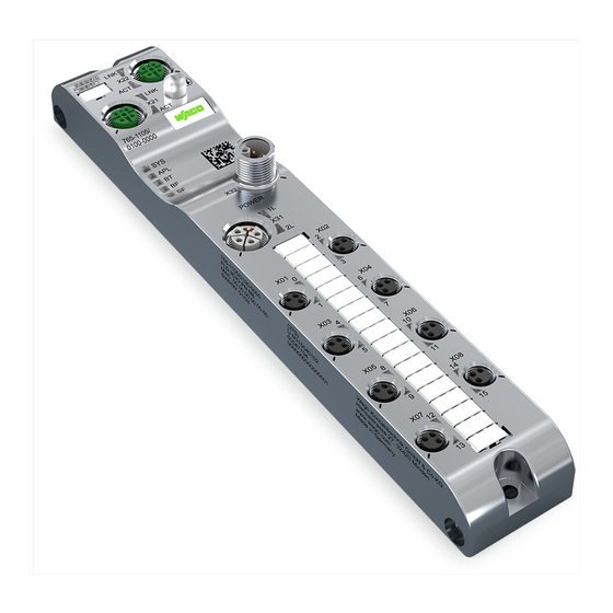
Properties 765-1205/0100-0000 Properties 4.1 View Figure 1: View Table 3: Legend for “View” Figure Function Position Custom Name Description ® ETHERNET ETHERNET interface, M12, D-coded, EtherCAT -IN port Product manual | Version: 1.0.0 8DIO FLD EC DC 24V 2.0A... -
Page 15: Connections
765-1205/0100-0000 Properties Function Position Custom Name Description L/A (X21) Link/activity LED for port X21 LED with no function ® ETHERNET interface, M12, D-coded, EtherCAT port L/A (X22) Link/activity LED for port X22 LED with no function ® ® ® Bluetooth... -
Page 16: Communication Interfaces
Properties 765-1205/0100-0000 Table 4: Supply voltage Supply Voltage In- Supply Voltage Signal Description Output 24 VDC supply voltage U for system and sensor/actuator 2L− Reference potential for 2L 1L− Reference potential for 1L 24 VDC auxiliary/control voltage U Functional ground M12, L-coded, plug,... -
Page 17: Network Connections
765-1205/0100-0000 Properties 4.2.3 Network Connections 4.2.3.1 ETHERNET Interfaces Table 7: ETHERNET Interfaces ETHERNET Signal Description Positive send data Positive receive data TX– Negative send data RX– Negative receive data Housing Shield Shield connection; housing is connected to functional ground M12, D-coded, socket, 4-pin 4.3 Circuit Diagram... -
Page 18: Mechanical Data
Properties 765-1205/0100-0000 4.4.2 Mechanical Data Table 9: Mechanical Data Property Value Width 35 mm Height 30 mm Length 210 mm Weight 380 g Housing Zinc Die Casting Mounting type Screw mount, 2 × M4 Tightening torque M4: 1.2 Nm Mounting holes Diameter: 4.5 mm... -
Page 19: Power Supply
765-1205/0100-0000 Properties Property Value Circuit High-side driver The digital output is not resistant to reverse power feeding. The input voltage must not exceed the supply voltage. Voltage drop through high-side path Less than 250 mV Self-protection Overcurrent, overload, overtemperature and overvolt- Maximum capacitive load 100 μF parallel to 12 Ω;... -
Page 20: Electrical Safety
Properties 765-1205/0100-0000 Parameters Value additional modules are connected to X32 (PWR OUT), it may be necessary for the maximum total current to be monitored with external power supply management. Maximum current: Observe derating as a function of surrounding air temperature. -
Page 21: Derating
765-1205/0100-0000 Properties ® Table 16: EtherCAT Slave Parameters Value Input data 4 bytes Output data 3 bytes Type Complex slave Features Emergency SYNC manager Supported protocols SDO server CoE (CANopen over EtherCAT) EoE (Ethernet over EtherCAT) FoE (File Access over EtherCAT) -
Page 22: Regulations And Standards
The product provides measured values for temperature and current, which you can display with WAGO Webserver I/O Field or read out via OPC UA. The following figure shows the maximum permissible current (I) that can flow into the product as a function of the surrounding air temperature (T). - Page 23 < 20 mW Certificate number: R20-0936-01-TEC (Slimline) FCC ID: 2AKUE-SLIMLINE ISED Certificate number: 22322-SLIMLINE Note More information on approvals You can find detailed information on the approvals online at: ü www.wago.com/<item number> Product manual | Version: 1.0.0 8DIO FLD EC DC 24V 2.0A...
-
Page 24: Functions
Functions 765-1205/0100-0000 Functions 5.1 Process Image ® EtherCAT uses process data objects (PDO) to transfer process data. Process data is ® ® transferred from the EtherCAT master to the EtherCAT slave with objects 0x1600, 0x1601 etc.; these data objects are called receive PDOs (RxPDOs). Process data is ®... -
Page 25: Table 23 Object 0X1A11: Assignment Of "New Message Available
765-1205/0100-0000 Functions Table 23: Object 0x1A11: Assignment of “New Message Available” Index Subindex Size Name Description 0x10F3.04 1 bit New Message Avail- Overwrite mode: able Flag 0: newest message has been read 1: newest message has not been read Acknowledgment mode:... -
Page 26: Forcing
The “Forcing” function can be accessed through the following tools: • WAGO I/O Field Webserver • WAGO I/O Field app on mobile devices Systems like SPS, TIA Portal and the like also have forcing functions. Such forcing func- tions should not be confused with the ones described in this section and will not be con- sidered within the context of this section. -
Page 27: Overload Protection
765 modules via EtherCAT WAGO I/O Field Webserver The WAGO I/O Field Webserver is a Webserver that is integrated into the 765 Series module. Using a Web browser, the user can view the Web pages and dis- play and modify parameters. -
Page 28: Wago Webserver I/O Field
I/O Field Webserver, the WAGO I/O Field app or the OPC UA client are overwritten. If you have changed parameters of the port configuration via the WAGO I/O Field Web- server, the WAGO I/O Field app or the OPC UA Client, please note that these changes ®... -
Page 29: Wago I/O Field App
765-1205/0100-0000 Functions Function overview The following overview shows the functions offered by WAGO Webserver I/O Field that is integrated into the product and the menu items/tabs in the user interface that can be used to address these functions: Table 29: Function Overview for WAGO I/O Field Webserver for Digital Input/Output Modules... -
Page 30: Communication Interfaces
You can find Product-specific information on the WAGO App I/O Field in the online help for the app. An iOS version of the WAGO I/O Field app is available for free in the Apple App Store, and an Android version in the Google Play Store. -
Page 31: Ethercat
765-1205/0100-0000 Functions 5.6.1 EtherCAT ® The module exchanges the process data with the controller via EtherCAT . The process data communication requires the controller and module to be configured and parameter- ized. 5.6.2 OPC UA Server The module has an integrated OPC UA server. -
Page 32: Planning
• Do not connect control components and control networks to an open network such as the Internet or an office network. WAGO recommends protecting control components and control networks against unauthorized outside access by using a firewall. • Limit physical and electronic access to all automation components to authorized per- sonnel only. -
Page 33: Power Supply Concept
765-1205/0100-0000 Planning 6.2 Power Supply Concept 6.2.1 Design Power Supply NOTICE Device damage if permissible current feedthrough exceeded There is a risk of damage to the device and/or other devices connected to it if the maxi- mum permissible current feedthrough is exceeded. - Page 34 Planning 765-1205/0100-0000 – Rule 1: Take maximum load capacity of each connection contact (pin) into ac- count – Rule 2: Take 1L and 2L current feedthrough into account • Ports X01, X02 etc. – Rule 3: The current load of pin 3 must not exceed 4 A, since the sum of the pin 1 and 4 currents flows back through pin 3.
-
Page 35: Table 31 Upper Limits For Current On The Individual Pins Of The Connections
765-1205/0100-0000 Planning termined by the current load capacity of the pluggable connector on the input supply con- nection and the PCB. This is max. 16 A. The total current must not exceed this current load capacity. Note the following: 1. When using digital outputs, the current feedthrough must be reduced by the current that flows through these outputs, for example. -
Page 36: Table 32 Module 0765-1205/0100-0000 - Currents In Supply Cable
Planning 765-1205/0100-0000 Current Description Total current for supply cable 1 at digital input/output X0i (i.e., port X01, X01_1L X02, ... , X04); corresponds to current I on pin 3 (ground). This X02_1L ... , X04_1L X0i_pin3_1L current is the sum of the currents at pins 1 and 4 of digital input/output... -
Page 37: Requirements On The Power Supply
765-1205/0100-0000 Planning 6.2.2 Requirements on the Power Supply Power Source Note PELV or SELV power source required Only device the product with 24 VDC PELV (Protective Extra Low Voltage) or SELV (Safety Extra Low Voltage) voltage sources. Failure to do so may result in electric shock. -
Page 38: Power Supply Examples
Planning 765-1205/0100-0000 6.2.4 Power Supply Examples The product can be powered alone with its operating voltage or form part of a power sup- ply group along with multiple products. Power supply groups of multiple products can be formed in two ways: 1. -
Page 39: Settings Options
765-1205/0100-0000 Planning These do not exceed the maximum permissible value of 16 A per supply cable and are thus permissible. Example of a Power Supply Group via PWR OUT If you connect another device to the PWR OUT (X32) power supply output, this forms a supply group. -
Page 40: Table 36 Port Parameters
1: Disable activation The Bluetooth interface cannot be enabled of BT interface by an optical signal of a mobile device and in connection with the WAGO I/O Field app. ® 0x2003.0 BT timeout 6 … 59 [s] Switch-off time of the Bluetooth interface if not used;... - Page 41 765-1205/0100-0000 Planning Index Value Range Value Range Default Description Subindex 30: 3 ms filter time Filter time setting for detecting a signal change of the pin 2 digital input signal. The 150: 15 ms filter time filter time is the amount of time the signal 200: 20 ms filter time...
-
Page 42: Transport And Storage
Transport and Storage 765-1205/0100-0000 Transport and Storage The original packaging offers optimal protection during transport and storage. • Store the product in suitable packaging, preferably the original packaging. • Only transport the product in suitable containers/packaging. • Make sure the product contacts are not contaminated or damaged during packing or unpacking. -
Page 43: Installation And Removal
765-1205/0100-0000 Installation and Removal Installation and Removal 8.1 Installation 8.1.1 Tools Required for Installation The following tools are required for installation: • Allen wrench for the M4 hex head mounting screws The following additional items are only required for installation where no threaded hole is present: •... -
Page 44: Note On Protecting Against Heat Generation By The Product
Installation and Removal 765-1205/0100-0000 • When mounting, be sure not to contaminate the connections. The contamination dam- ages the contacts, which can limit the reliability of the contacts. 8.1.4 Note on Protecting against Heat Generation by the Product During operation, the product can get hot! Therefore, always note the following informa- tion: •... -
Page 45: Removal
765-1205/0100-0000 Installation and Removal • Grounding can be done separately via a cable lug and the mounting hole if the module is installed on a non-conductive subsurface Ensure proper contacts and a sufficient cable cross-section. 8.2 Removal 8.2.1 Tools Required for Removal For removal, you need an Allen key to unscrew the M4 cylinder head hex screws per DIN 912/ISO 4762. -
Page 46: Connection
Connection 765-1205/0100-0000 Connection 9.1 General Information on Installation When laying cables, the local conditions and the applicable regulations are crucial for im- plementation. Be sure to maintain the minimum clearances between the cabling and possible sources of interference (including machines, welding equipment and power lines) to prevent loss and corruption of data. - Page 47 Note that the connection for the additional supply voltage is not monitored for overload. If the maximum current carrying capacity is exceeded, this can damage the pluggable con- nectors. WAGO recommends using pre-assembled cables. Power supply 2L is provided to power actuators at specific ports. It can also be passed on to additional devices.
- Page 48 Connection 765-1205/0100-0000 Figure 5: Example of Feeding in and Passing on the Supply Voltages In connection with this figure, note that the cables illustrated for current paths 1L and 2L are realized not as separate cables, but rather as separate wires within one common ca- ble.
-
Page 49: Connecting Cables
Cable cross-section 9.3 Connecting Cables WAGO recommends using 765 Series connecting cables, pluggable connectors and ac- cessories for 756 Series products, which have been tailored specifically to the WAGO I/O System Field. 8 Connection Technology [} 18] The tightening torques given in section apply to the pluggable connectors of the connecting cables. - Page 50 3. Tighten the pluggable connector using the knurled-head screw. Connecting Multiple Products to One ETHERNET Network The fieldbus module of the WAGO I/O System Field has two connections, IN and OUT, to allow wiring of a line topology. Multiple products can be connected to the ETHERNET network as shown in the following example: 1.
-
Page 51: Connect Sensors/Actuators
765-1205/0100-0000 Connection ® Figure 7: Line Topology for EtherCAT Networks (Module Image May Differ) 9.5 Connect Sensors/Actuators The sensor/actuator cable provides power to the connected sensors/actuators and trans- fers the sensor and actuator signals. 8 Design Power Note the current load capacity of the supply contacts; see “Rule 3” in Supply [} 33], section Rule 3: Ports X01, X02 etc. -
Page 52: Table 37 Connect Digital Input Or Output
Connection 765-1205/0100-0000 Ethernet Ethernet PWR OUT PWR IN Figure 8: Schematic Circuit Diagram of the Power Supply The following table shows the connection options for digital inputs and outputs. Table 37: Connect digital input or output Connection Option Description Connection of a digital input Required port configuration: pin 4 as digital input Product manual | Version: 1.0.0... - Page 53 765-1205/0100-0000 Connection Connection Option Description Connection of a digital output Required port configuration: pin 4 as digital output Product manual | Version: 1.0.0 8DIO FLD EC DC 24V 2.0A...
-
Page 54: Commissioning
The module requires an IP address if IP-based communication is to be used. This is the case, for example, if the WAGO I/O Field Webserver or the OPC UA server of the module is used. The module has no IP address when delivered. The module gets the IP address ®... -
Page 55: Selecting The Module
10.3.1 WAGO Webserver I/O Field 10.3.1.1 Call WAGO Webserver I/O Field This section describes how you can use the integrated software WAGO I/O Field Web- server to get access to detailed information on the current operating state of the product and make settings to affect the product’s behavior. -
Page 56: User Interface Of The Wago Webserver I/O Field
10.3.1.2 User Interface of the WAGO Webserver I/O Field Figure 10: Dashboard Menu Item, Main Page When the user interface of the WAGO I/O Field Webserver opens, the main page of the Dashboard appears first. It shows the following product information: Table 38: Data on the “Dashboard”... -
Page 57: Maintenance Information
• A list of the licensed software components the product contains • A link for each licensed software component to the associated license terms 10.3.1.3 Opening the Product Information via WAGO Webserver I/O Field 10.3.1.3.1 Display Port Information For each of the digital inputs/outputs of the module (port X01, port X02, etc.), individual port information can be found on the Information, Status, Configuration and Process data tabs. -
Page 58: Displaying Measured Values And Information On Connected Sensors/Actuators
Commissioning 765-1205/0100-0000 10.3.1.3.2 Displaying Measured Values and Information on Connected Sensors/Actuators Figure 11: Information Tab, Port XX Menu Item The Information tab shows the following information: • The measured values and states of the port diagnostics • The information on connected sensors/actuators... -
Page 59: Display Port Status Information
765-1205/0100-0000 Commissioning 10.3.1.3.3 Display Port Status Information Figure 12: Port XX Menu Item, Status Tab The Status tab shows status information for pin 4 of the selected port. Proceed as follows to display the status information on a specific port: 1. From the main menu of the Webserver (left), select the menu item which you want to view information about. -
Page 60: Parameterizing The Module Via The Wago I/O Field Webserver
765-1205/0100-0000 Figure 13: Port XX Menu Item, Process Data Tab 10.3.1.4 Parameterizing the Module via the WAGO I/O Field Webserver You can make the following settings on the module with WAGO Webserver I/O Field: 8 Configuring Ports [} 61] • 8 Configuring IP Parameters [} 62] •... -
Page 61: Configure Ports
765-1205/0100-0000 Commissioning 10.3.1.4.1 Configure Ports Figure 14: Port XX Menu Item, Configuration Tab Table 40: Port Configuration Settings Name Type Description Port mode (pin 4) Drop-down menu Port operating mode (configuration of pin 4) Digital input signal filter Drop-down menu Filter time for digital input signals on pin 4 (only for (pin 4) “Port mode (pin 4)”... -
Page 62: Configuring Ip Parameters
Commissioning 765-1205/0100-0000 Table 41: “Port Mode” Drop-Down Menu: Selecting the Operating Mode for Pin 4 of the Selected IO-Link Port Selection Option Description Digital input, normally The port is used as a digital input. All elements of the port configuration are ig- open nored except for the input and output data length. -
Page 63: Storing Maintenance Information
765-1205/0100-0000 Commissioning 10.3.1.4.3 Storing Maintenance Information On the Maintenance Information tab, you can store maintenance information, such as the device name, the installation location and date, contact information, a description text or the date of the last and next product service. -
Page 64: Update Firmware
4. Click the [Apply] button. ð Your changes take effect. 10.3.1.4.4 Update Firmware With the Firmware upgrade tab, WAGO Webserver I/O Field provides the option to up- date the product firmware. Figure 17: Settings Menu Item, Firmware Upgrade Tab Product manual | Version: 1.0.0... - Page 65 To update the firmware, you need a firmware container file: FWUPDATE.ZIP. You can get it from the Downloads section of the WAGO website: ü http://www.wago.com. Proceed as follows to update the firmware: 1. In the left-hand column of the WAGO I/O Field Webserver, click the Settings menu item. ð The Device configuration tab appears.
-
Page 66: Resetsetting The Module To The Factory Settings
Reset All All Settings To reset the module to the factory settings, proceed as follows: 1. In the left-hand column of the WAGO I/O Field Webserver, click the Settings menu item. ð The Device configuration tab appears. 2. Select the Factory reset tab. - Page 67 • Switching the Bluetooth wireless connection on/off ® • Switching the Bluetooth LED on/off ® Proceed as follows to access these Bluetooth functions in the WAGO I/O Field Web- server: ® • Open the Bluetooth tab. ® ð The Bluetooth tab appears.
-
Page 68: Table 44 Status Of The Last Bluetooth® Firmware Update
® To enable the Bluetooth interface, you must have the WAGO I/O Field app installed on the smartphone or tablet. Proceed as follows: ® • A DM code appears in the “Information” section of the Bluetooth tab. -
Page 69: Logging Users On And Off And Managing Them
765-1205/0100-0000 Commissioning Performing a Reset ® Proceed as follows to reset the Bluetooth firmware: • Click Reset. ð The Bluetooth ® firmware is reverted and restarts. ® Switching the Bluetooth Interface Wireless Transmitter on/off ® To switch the Bluetooth interface wireless transmitter on: •... - Page 70 2. Enter your username and password into the corresponding fields. 3. Click the [Sign in] button. ð If you have entered a known username correctly, you can now work with the WAGO I/ O Field Webserver with this user’s specified rights. The username that was used to log on is shown in the upper left-hand corner.
- Page 71 765-1205/0100-0000 Commissioning Figure 21: User Administration Menu Item (Initial State) The user root with pre-set password password exists by default; see first row. An additional user can be created in the second row. Proceed as follows: 1. In the Username field, enter the username to use for the user. Users that are al- ready in use are not allowed here.
-
Page 72: Forcing Digital Inputs And Outputs
Commissioning 765-1205/0100-0000 ð The new user is created and assigned the selected role. Removing Users To remove an existing user from the product’s user administration, proceed as follows: • Click the red square with the white “x” to the right of the user you want to remove. -
Page 73: Wago I/O Field App
As long as one user is accessing the forcing functionality through a forcing medium, e.g., the WAGO I/O Field Webserver, it is locked for all other users of the module. They cannot access the forcing functionality until the user that is active now terminates his or her ac- cess. -
Page 74: Parameterizing The Product Via Opc Ua
Commissioning 765-1205/0100-0000 The OPC UA client establishes a connection via the following URL: opc.tcp://IP-address:4840 For IP-address, use the device’s IP address. The client can access device parameters anonymously (only read access) or with a user- name/password (read/write access). The username and password are set with the Field IO Webserver. -
Page 75: Configure Parameters
765-1205/0100-0000 Commissioning Node Name Node Class Access Description Model Variable Read Model name of the device: “IO System Field-765-xxxx” ProductCode Variable Read Product code of the device: “765-xxxx/xxxx- xxxx” RevisionCounter Variable Read Hardware version of the device SerialNumber Variable Read... -
Page 76: Read Process Data
Commissioning 765-1205/0100-0000 The following table lists port-specific configuration parameters. Table 48: Port-Specific Configuration Parameters Node Name Node Class Access Default Description OverCurrentPin1, Over- Variable Read Warning level for current upper limit on pin 1, pin CurrentPin2, OverCur- 2 or pin 4; unit: 1 mA... -
Page 77: Read Diagnostic Information
765-1205/0100-0000 Commissioning Node Name Node Class Access Description MeanVoltageL Variable Read Average voltage in supply cable 1; unit: mV MeanVoltageL2 Variable Read Average voltage in supply cable 2; unit: mV The OPC UA server provides nodes with measured values for each port and each individ- ual pin. -
Page 78: Read Statistics
Commissioning 765-1205/0100-0000 10.3.3.1.6 Read Statistics The OPC UA server provides nodes with statistical information. For example, the OPC UA client can read out the maximum measured current on pin 1 of a port in the MaxCur- rentPin1 node. The path to this node is: Root >... -
Page 79: Diagnostics
765-1205/0100-0000 Diagnostics Diagnostics 11.1 Diagnostics via Indicators Power Supply Status The 1L and 2L LEDs indicate the status of the supply voltages. Table 54: Supply Voltage Status, 1L and 2L Color State Description Duo LED, red/green Green 1L supply voltage ok 1L undervoltage (voltage between 11 V and... -
Page 80: Table 58 Ethercat® Slave Status
Diagnostics 765-1205/0100-0000 Color State Description LED without function ® EtherCAT Slave Status ® The following table describes the LED states of the EtherCAT slave. ® Table 58: EtherCAT Slave Status Color State Description Duo LED, red/green INT: The module is in state INIT. -
Page 81: Diagnostics Via Ethercat
765-1205/0100-0000 Diagnostics Color State Description Green Link: The module has a connection to the ETHERNET, but is not sending/receiving Ethernet frames. Green Flickering (load-de- Activity: The module has a connection to pendent) ETHERNET and is sending/receiving Ether- net frames. The module is not connected to the ETH- ERNET. -
Page 82: Subindex 0: Highest Supported Subindex
Diagnostics 765-1205/0100-0000 Subindex Name Explanation Type Flags Default Maximum Messages Number of diagnostic messages that can UINT8 be stored in the diagnostic history Newest Message Subindex of the newest logged diagnostic UINT8 message Newest Acknowl- Newest acknowledged message UINT8 edged Message... - Page 83 765-1205/0100-0000 Diagnostics Overwrite Mode Read = 0: If the queue for diagnostic messages is overwritten, the EtherCAT slave sets subindex 3 to 0. Writing = 0: If a value of 0 is written to subindex 3, the EtherCAT slave deletes subindex 2, subindex 3, subindex 4 and subindex 5 bit 5 or sets them to 0.
-
Page 84: Subindex 4: New Messages Available
Diagnostics 765-1205/0100-0000 11.2.1.5 Subindex 4: New Messages Available This subindex contains the subindex of the newest acknowledged diagnostic message. It can be both read and written. In both cases, the meaning of the values depends on the current mode. The modes are overwrite mode (subindex 5, bit 4 = 0) and acknowledge mode (subindex 5, bit 4 = 1). -
Page 85: Subindexes 6-69: Diagnosis Message (Write-Protected)
765-1205/0100-0000 Diagnostics 11.2.1.7 Subindexes 6–69: Diagnosis Message (Write-Protected) Depending on subindex 1, the EtherCAT slave can store up to 64 diagnostic messages. In the process, the first message is stored in subindex 6, the second in subindex 7 etc. When the buffer is full, the EtherCAT slave overwrites subindex 6 etc., so the last diag- nostic messages are accessible to the EtherCAT master. -
Page 86: Emergency Error Codes
Diagnostics 765-1205/0100-0000 Parame- Datatype Description ters Parame- UINT16 Describes the type of parameter 2 ter 2 Bits 12–15 = 0 Bits 0–11 = data type index of the data type of parameter 2 Flags 0x0007: UINT32 The corresponding text parameters and formatting are de- scribed in document ETG.2000. -
Page 87: Table 69 General Alarms
765-1205/0100-0000 Diagnostics Emergency Error Code (hex) Description 22xx Current inside the device 23xx Current, device output side 30xx Voltage 31xx Mains Voltage 32xx Voltage inside the device 33xx Output Voltage 40xx Temperature 41xx Ambient Temperature 42xx Device Temperature 50xx Device Hardware... -
Page 88: Events Triggered By The Io-Link Master
Diagnostics 765-1205/0100-0000 Emergency Alarm Description Remedy Error Code (hex) The total current in supply line 1L has ex- ceeded the upper limiting value. 0xFF05 Undertempera- Undertemperature Thermally insulate the device ture The device temperature has fallen below the lower limiting value. -
Page 89: Events Triggered By The Io-Link Device
765-1205/0100-0000 Diagnostics IO-Link Event Code Description Remedy 0x180A Backup inconsistency Eliminate identity error 0x180B Backup inconsistency Unspecified error during data storage 0x180C Backup inconsistency Eliminate upload error 0x180D Parameter inconsistency Eliminate download error 0x180E P24 (class B) missing or has under-... -
Page 90: Error Register
Diagnostics 765-1205/0100-0000 IO-Link Event Code Description of the Error Function Corrective Action on the Connected on the Connected IO-Link Device IO-Link Device 0x6321 Missing parameter(s) Check datasheet 0x6350 Parameter change Check configuration 0x7700 Wire break on a lower-level device Check installation 0x7701 –... -
Page 91: Service
Service Service 12.1 Resetting to Factory Settings The device can be reset to the factory settings. Use the WAGO I/O Field Webserver for this purpose. You can find information on the procedure under Parameterizing the Module via the 8 Resetsetting the Module to the Factory Settings WAGO I/O Field Webserver >... -
Page 92: Decommissioning
Decommissioning 765-1205/0100-0000 Decommissioning 13.1 Entsorgung und Recycling Table 73: WEEE Mark Logo Description Electrical and electronic equipment may not be disposed of with household waste. This also applies to products without this mark. Electrical and electronic equipment contain materials and substances that can be harmful to the environment and health. -
Page 93: Appendix
EU Declaration of Conformity Hereby, WAGO Kontakttechnik GmbH & Co. KG declares that the radio equipment type 0765-1205/0100-0000 is in compliance with Directive 2014/53/EU. The full text of the EU declaration of conformity is available at the following internet address: ü www.wago.com... -
Page 94: Operational Description
Appendix 765-1205/0100-0000 Changes or modifications made to this equipment not expressly approved by WAGO Kontakttechnik GmbH & Co. KG may void the FCC authorization to operate this equip- ment. 14.2 Operational Description Product description The product 0765-1205/0100-0000 is used to capture and output digital field signals, e.g., from sensors and actuators, which have been sent or received by a higher-level con- troller. -
Page 95: Protected Rights
765-1205/0100-0000 Appendix We declare that we meet the EN 62479 standard with respect to the limiting value for low powers less than 20 mW. Therefore, the product fundamentally corresponds to the Euro- pean limiting values for high-frequency radiation. Product Designs SlimLine (W × H × D) 35 ×... - Page 96 Appendix 765-1205/0100-0000 ® • Modbus is a registered trademark of Schneider Electric, licensed for Modbus Organi- zation, Inc. • OPC UA is a registered trademark of the OPC Foundation. ® • PROFIBUS is a registered trademark of the PROFIBUS Nutzerorganisation e.V.
- Page 97 Overview of Parameterization Tools .................. Table 28 Parameterization Overview....................Table 29 Function Overview for WAGO I/O Field Webserver for Digital Input/Output Modules ..Table 30 Additional documentation....................Table 31 Upper Limits for Current on the Individual Pins of the Connections ........
- Page 98 List of Tables 765-1205/0100-0000 Table 37 Connect digital input or output ................... Table 38 Data on the “Dashboard” Page ..................Table 39 Tab for port information (digital inputs/outputs X01, X02, etc.).......... Table 40 Port Configuration Settings ....................Table 41 “Port Mode” Drop-Down Menu: Selecting the Operating Mode for Pin 4 of the Selected IO-Link Port........................
- Page 99 765-1205/0100-0000 List of Tables Table 74 Bluetooth® Transmitter ...................... Table 75 Temperature range ......................Table 76 Voltage range........................Product manual | Version: 1.0.0 8DIO FLD EC DC 24V 2.0A...
- Page 100 List of Figures 765-1205/0100-0000 List of Figures Figure 1 View ..........................Figure 2 Circuit Diagram for Each Port ..................Figure 3 Derating, 0765-1205/0100-0000 ................... Figure 4 Connection Example with Individual Power Supply (Module Image May Vary).... Figure 5 Example of Feeding in and Passing on the Supply Voltages ........
- Page 101 765-1205/0100-0000 List of Figures Product manual | Version: 1.0.0 8DIO FLD EC DC 24V 2.0A...
- Page 102 WAGO is a registered trademark of WAGO Verwaltungsgesellschaft mbH. Copyright – WAGO Kontakttechnik GmbH & Co. KG – All rights reserved. The content and structure of the WAGO websites, catalogs, videos and other WAGO media are subject to copyright. Distribution or modification of the contents of these pages and videos is prohibited. Furthermore, the content may neither be copied nor made available to third parties for...
Need help?
Do you have a question about the 765-1205/0100-0000 and is the answer not in the manual?
Questions and answers