B&R Automation PC 3100 User Manual
Hide thumbs
Also See for Automation PC 3100:
- User manual (204 pages) ,
- User manual (277 pages) ,
- User manual (348 pages)
Table of Contents
Advertisement
Quick Links
Automation PC 3100
User's manual
Version: 2.10 (January 2021)
Order no.: MAAPC3100-ENG
Translation of the original documentation
All values in this manual are current as of its creation. We reserve the right to change the contents of this manual
without notice. B&R Industrial Automation GmbH is not liable for technical or editorial errors and defects in this
manual. In addition, B&R Industrial Automation GmbH assumes no liability for damages that are directly or indirectly
attributable to the delivery, performance or use of this material. We point out that the software and hardware
designations and brand names of the respective companies used in this document are subject to general trademark,
brand or patent protection.
Advertisement
Table of Contents

Subscribe to Our Youtube Channel
Related Manuals for B&R Automation PC 3100


Summary of Contents for B&R Automation PC 3100
- Page 1 Automation PC 3100 User's manual Version: 2.10 (January 2021) Order no.: MAAPC3100-ENG Translation of the original documentation All values in this manual are current as of its creation. We reserve the right to change the contents of this manual without notice. B&R Industrial Automation GmbH is not liable for technical or editorial errors and defects in this manual.
-
Page 2: Table Of Contents
4.4.3 Spacing for air circulation........................29 4.4.4 Mounting orientations..........................30 4.4.5 Weight specifications..........................31 4.5 Environmental properties..........................32 4.5.1 Temperature specifications........................32 4.5.1.1 Maximum ambient temperature for worst-case operation..............32 4.5.1.2 Minimum ambient temperature for worst-case operation..............32 Automation PC 3100 User's manual V 2.10... - Page 3 4.7.4.11 5ACCIF02.CANE-000........................83 4.7.4.12 5ACCIF02.FPLK-000........................87 4.7.4.13 5ACCIF02.FPLS-000........................90 4.7.4.14 5ACCIF02.FPSC-000........................93 4.7.4.15 5ACCIF02.ISS0-000.........................98 4.7.4.16 5ACCIF04.FPLK-000........................101 4.7.5 Mass storage options..........................103 4.7.5.1 5ACCMS01.MDT2-000........................103 4.7.5.2 5ACCMSM2.xxxx-000........................105 4.7.6 Uninterruptible power supply (UPS)......................107 4.7.6.1 Requirements........................... 107 4.7.6.2 5AC901.IUPS-00..........................108 Automation PC 3100 User's manual V 2.10...
- Page 4 7.1.6.1 Main..............................143 7.1.6.2 Advanced............................145 7.1.6.3 Security.............................169 7.1.6.4 Power............................... 171 7.1.6.5 Boot..............................172 7.1.6.6 Exit..............................175 7.2 Upgrade information............................176 7.2.1 UEFI BIOS upgrade..........................176 7.2.1.1 BIOS upgrade..........................176 7.2.1.2 Procedure in the EFI shell....................... 176 Automation PC 3100 User's manual V 2.10...
- Page 5 7.4.4 B&R Linux 9 (GNU/Linux)........................200 7.4.4.1 General information..........................200 7.4.4.2 Order data............................200 7.4.4.3 Overview............................200 7.4.4.4 Features............................200 7.4.4.5 Installation............................200 7.4.4.6 Drivers.............................. 201 7.4.5 Automation Runtime..........................202 7.4.5.1 General information..........................202 7.4.5.2 Order data............................202 Automation PC 3100 User's manual V 2.10...
- Page 6 9.5.1.3 Technical data..........................228 9.6 USB mass storage device.......................... 229 9.7 Cables................................. 229 10 International and national certifications............230 10.1 Directives and declarations........................230 10.1.1 CE marking............................230 10.1.2 EMC Directive............................230 10.2 Certifications..............................231 10.2.1 UL certification............................. 231 Automation PC 3100 User's manual V 2.10...
- Page 7 10.2.6.1 General safety guidelines......................233 10.2.6.2 Assembly and installation......................233 10.2.6.3 Operation............................233 10.2.6.4 Servicing, disturbances and disassembly..................234 10.2.6.5 USB connection with the Automation PC 3100................235 10.2.6.6 USB connection with optional DisplayPort graphics option............237 11 Environmentally friendly disposal..............239 11.1 Separation of materials..........................239 Appendix A ......................
-
Page 8: Introduction
"B&R Linux 9 (GNU/ Linux)" on page 200, "Automation Runtime" on page 202, "B&R Hypervisor" on page 205 "mapp Technology" on page 211. ° Updated section "Installing the interface option and DDR4 SDRAM" on page 217. Automation PC 3100 User's manual V 2.10... -
Page 9: Information About This Document
Over 6 to 30 mm ±0.2 mm Over 30 to 120 mm ±0.3 mm Over 120 to 400 mm ±0.5 mm Over 400 to 1000 mm ±0.8 mm Table 2: Nominal dimension ranges Automation PC 3100 User's manual V 2.10... -
Page 10: General Safety Guidelines
Electronic devices are generally not failsafe. If the programmable logic controller, operating or control device or uninterruptible power supply fails, the user is responsible for ensuring that connected devices (such as motors) are brought to a safe state. Automation PC 3100 User's manual V 2.10... -
Page 11: Transport And Storage
(e.g. cutout installation). The back of all devices must be protected against the ingress of dust and moisture, however, or the dust deposits must be removed at suitable intervals. Automation PC 3100 User's manual V 2.10... -
Page 12: Programs, Viruses And Malicious Programs
The term "control systems" refers to all types of B&R products such as controllers (e.g. X20), HMI systems (e.g. Power Panel T30), process control systems (e.g. APROL) and supporting systems such as engineering workstations with Automation Studio. Automation PC 3100 User's manual V 2.10... -
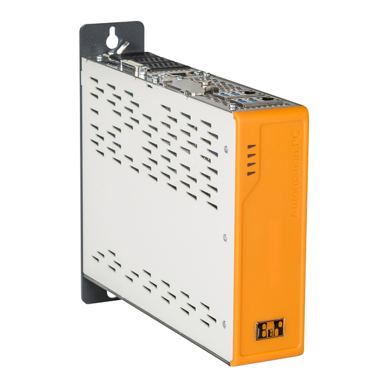
Page 13: System Overview
Core i7. This allows the processing power to be adapted exactly as needed to the respective application. All variants are fanless, which means that the Automation PC 3100 has no rotating parts at all. This makes maintenance tasks like replacing air filters a thing of the past. The scalable memory options range from 4 to 32 GB. This means that this PC generation can also handle very demanding applications. -
Page 14: Features
• Battery-backed RTC • Fanless operation • 3x interface option slots • TPM 2.0 security • Additional graphics options (DP/DVI/SDL/SDL4) • +24 VDC supply voltage • Up to 1024 GB M.2 mass storage Automation PC 3100 User's manual V 2.10... -
Page 15: Configuration
5AC901.IRDY-00 5ACCIF02.FPLS-000 5AC901.ICAN-01 5AC901.ISIO-00 5ACCIF02.FPSC-000 5AC901.IETH-00 5AC901.ISRM-00 5ACCIF02.ISS0-000 5ACCIF04.FPLK-000 Optional, select 1 of each Cables UPS module Battery unit 5CAUPS.0005-01 5CAUPS.0010-01 5AC901.IUPS-00 5AC901.BUPS-00 5CAUPS.0013-01 5AC901.IUPS-01 5AC901.BUPS-01 5CAUPS.0030-01 Accessories Optional selection 5MMUSB.2048-01 5MMUSB.4096-01 5MMUSB.032G-02 Automation PC 3100 User's manual V 2.10... - Page 16 Select a graphics option or mass storage option. The UPS module can only be operated in the IF option 1 slot, and the battery unit compatible with the UPS module must be used. Automation PC 3100 User's manual V 2.10...
-
Page 17: Overview
Automation Runtime Embedded TG license Terminal blocks 0TB2104.8000 Connector 24 VDC - 4-pin female - Screw clamp terminal block 2.5 mm² Uninterruptible power supply 5AC901.BUPS-00 Battery unit 4.5 Ah - For UPS 5AC901.IUPS-00 Automation PC 3100 User's manual V 2.10... - Page 18 Windows 10 IoT Enterprise 2019 LTSC: - 64-bit - Value - Multilingual - License - Only available with a new device 5SWW10.1100-MUL Windows 10 IoT Enterprise 2019 LTSC: - 64-bit - High End - Multilingual - License - Only available with a new device Automation PC 3100 User's manual V 2.10...
-
Page 19: Technical Data
✓ USB1, USB2 USB 1.1 COM interface for touch Grounding screen Maximum cable length: 40 m Requirements • Automation Panel with SDL/DVI receiver • B&R industrial PC with SDL interface • SDL cable Automation PC 3100 User's manual V 2.10... -
Page 20: Sdl Operation With Usb Cable (Mode 2)
USB 2.0 COM interface for touch Grounding screen Maximum cable length: 5 m Requirements • Automation Panel with SDL/DVI receiver • B&R industrial PC with SDL interface • SDL cable, USB type A/B cable Automation PC 3100 User's manual V 2.10... -
Page 21: Dvi Operation
• B&R industrial PC with DVI interface • DVI cable, USB type A/B cable 4.1.2.3 General limitations • Key and LED data is not transferred. • Service and diagnostic data is not transferred. Automation PC 3100 User's manual V 2.10... - Page 22 Technical data • Updating the firmware of Automation Panels is not possible. • The maximum cable length is limited to 5 m. Automation PC 3100 User's manual V 2.10...
-
Page 23: Sdl4 Operation
° No SDL3/SDL4 cable is connected. ° There is no connection established yet between the SDL4 link module and SDL4 transmitter. This behavior can be avoided by appropriate configuration in BIOS or via the graphics driver. Automation PC 3100 User's manual V 2.10... -
Page 24: Product Information
The device number can be retrieved from the B&R website (www.br-automation.com) using the serial number of the device (login required). Information (serial number, material number, revision, delivery date and end of warranty) about all components installed in the system can be retrieved using the device number. Automation PC 3100 User's manual V 2.10... -
Page 25: Electrical Properties
Power 24 VDC supply input IF option 2 Magnetics Magnetics IF option 3 (Graphics option) Legend 2.0_Px USB 2.0 port x Internal interface 3.0_Px USB 3.0 port x External interface Internal interface, removable/configurable Automation PC 3100 User's manual V 2.10... -
Page 26: Power Calculation
Technical data 4.3.2 Power calculation In order to calculate the total power of the Automation PC 3100, the power ratings of the system unit used all other installed components must be added together. Information: Unless otherwise stated, the following specified maximum values and additional consumers are not taken into account. -
Page 27: Calculation Examples
1.5 W Graphics option 5ACCLI01.SD40-000 2.5 W + 2 W 4.5 W 2x CFast card 5CFAST.256G-10 2x 1.9 W (write) 3.8 W Total max.: 60.2 W Table 4: Power calculation with example configuration 2 Automation PC 3100 User's manual V 2.10... -
Page 28: Mechanical Properties
2D and 3D diagrams (DXF and STEP formats) can be downloaded from the B&R website (www.br-automation.com). 248.3 4.4.2 Drilling template Information: When installing the Automation PC 3100, spacing for air circulation and additional free space for op- erating and servicing the device must be taken into account. Detail A Scale 2:1 ø 5.5 ø... -
Page 29: Spacing For Air Circulation
If the specified spacing for air circulation cannot be maintained, the maximum specified temperatures of the temperature sensors (see "Temperature sensor positions" on page 36) must be monitored in the application and appropriate measures taken if these values are exceeded. Automation PC 3100 User's manual V 2.10... -
Page 30: Mounting Orientations
Inclination [°] Derating 0 to ±5 No limitation 0 to ±5 No limitation ±5 to ±175 5 to 175 Not allowed! ±175 to ±180 No limitation -5 to -175 ±175 to ±180 No limitation Automation PC 3100 User's manual V 2.10... -
Page 31: Weight Specifications
CFast cards 5CFAST.xxxx-10 5ACCLI02.DPO0-000 Graphics options 5ACCLI02.SDL0-000 5ACCLI02.SD40-000 5AC901.I232-00 5AC901.I485-00 5AC901.ICAN-00 5AC901.ICAN-01 5AC901.IHDA-00 5AC901.IRDY-00 5AC901.IPLK-00 5AC901.ISIO-00 Interface options 5AC901.ISRM-00 5AC901.IETH-00 5ACCIF02.CANE-000 5ACCIF02.FPLK-000 5ACCIF02.FPLS-000 5ACCIF02.FPSC-000 5ACCIF02.ISS0-000 5ACCIF04.FPLK-000 Mass storage options 5ACCMS01.MDT2-000 Without memory module. Automation PC 3100 User's manual V 2.10... -
Page 32: Environmental Properties
Mass storage options 5ACCMS01.MDT2-000 ✓ ✓ ✓ These values can be limited by the memory module used. 4.5.1.2 Minimum ambient temperature for worst-case operation The minimum ambient temperature for non-condensing operation is 0°C. Automation PC 3100 User's manual V 2.10... -
Page 33: Maximum Ambient Temperature For Typical Operation
✓ ✓ ✓ 5ACCIF02.ISS0-000 5ACCIF04.FPLK-000 ✓ ✓ Mass storage options 5ACCMS01.MDT2-000 ✓ ✓ Max. 15 W without USB Max. 17 W without USB These values can be limited by the memory module used. Automation PC 3100 User's manual V 2.10... -
Page 34: Determining The Ambient Temperature
5. The relevant test and assessment must be carried out individually by the user on site (reading out the tem- peratures in BIOS or using the ADI Control Center). See section "Information about typical conditions" on page Automation PC 3100 User's manual V 2.10... -
Page 35: Ambient Temperature For Storage And Transport
Microsoft Windows or B&R Linux operating systems. The measured temperature is a guide value for the immediate ambient temperature, but it may have been influenced by neighboring components. Self-Monitoring, Analysis and Reporting Technology Automation PC 3100 User's manual V 2.10... -
Page 36: Temperature Sensor Positions
Temperature of the MTCX processor 90°C System unit sensor 4 Temperature of the processor 95°C IF option 3 slot Graphics option Temperature of a graphics option (sensor integrated on the graphics option) Depends on the graphics option Automation PC 3100 User's manual V 2.10... -
Page 37: Relative Humidity
The specification refers to a device in its original packaging. 4.5.4 Degree of protection Under the following conditions, the Automation PC 3100 offers IP20 protection per EN 60529: • Correct installation of the Automation PC 3100 (see "Installation and wiring" on page 125) •... -
Page 38: Device Interfaces And Slots
"LED status indicators" on page 43 "SDL/DVI-D interface" on page 45 "Power button" on page 42 "IF option 3 slot" on page 49 "Reset button" on page 42 "CFast slots" on page 42 "Battery" on page 44 Automation PC 3100 User's manual V 2.10... -
Page 39: Vdc Power Supply
For example, a copper strip must be attached to the ground connection at a central grounding point of the control cabinet or system in which the device is installed. The wire cross section should be as large as possible (at least 2.5 mm²). Automation PC 3100 User's manual V 2.10... -
Page 40: Ethernet Interfaces
A special driver is required to operate the Ethernet controller. Drivers for approved operating systems are available for download in the Downloads section of the B&R website (www.br-automation.com). Information: Necessary drivers must be downloaded from the B&R website, not from manufacturer websites. Automation PC 3100 User's manual V 2.10... -
Page 41: Usb Interfaces
Full speed (12 Mbit/s) High speed (480 Mbit/s) Current-carrying capacity USB5 Max. 0.5 A Cable length Internal for Technology Guard The USB interface is protected by a maintenance-free "USB current-limiting switch" (max. 0.5 A). Automation PC 3100 User's manual V 2.10... -
Page 42: Cfast Slots
Pressing the reset button triggers a hardware/PCI reset. The PC is restarted. During a reset, the MTCX processor is not reset. Warning! Switching off the power without shutting down or resetting the system can result in data loss! Automation PC 3100 User's manual V 2.10... -
Page 43: Led Status Indicators
Application running Controlled by Automation Runtime (ARemb and AR- win). Application in SERVICE mode Controlled by Automation Runtime (ARemb and AR- win). Orange Blinking A license violation has occurred. S5: Soft-off S4: Hibernate (suspend-to-disk) Automation PC 3100 User's manual V 2.10... -
Page 44: Battery
As soon as the battery capacity is recognized as BAD (insufficient), retention of data is ensured for approximately another 500 hours. The battery must be replaced. When changing the battery, data is retained for approximately 10 minutes by a gold foil capacitor. Automation PC 3100 User's manual V 2.10... -
Page 45: Sdl/Dvi-D Interface
In SDL operation without USB type A/B cable, the USB transfer rate is limited to USB 1.1. A USB transfer rate of USB 2.0 is possible in DVI or SDL operation with a USB type A/B cable. Automation PC 3100 User's manual V 2.10... -
Page 46: Cable Lengths And Resolutions For Sdl Transfer
1920 x 1080 5CADVI.0018-00 5CADVI.0018-00 5CADVI.0018-00 5CADVI.0018-00 5CADVI.0018-00 5CADVI.0018-00 5CADVI.0018-00 5CADVI.0050-00 5CADVI.0050-00 5CADVI.0050-00 5CADVI.0050-00 5CADVI.0050-00 5CADVI.0050-00 5CADVI.0050-00 The maximum cable length for DVI transfer is limited to 5 m due to the USB specification. Automation PC 3100 User's manual V 2.10... -
Page 47: If Option 1 Slot
Technical data 4.6.11 IF option 1 slot Automation PC 3100 system units have 3 slots for interface options. The following table lists the interface options that can be used in the IF option 1 slot. IF option 1 slot Order number Interface option - Short description 5AC901.I232-00... -
Page 48: If Option 2 Slot
Technical data 4.6.12 IF option 2 slot Automation PC 3100 system units have 3 slots for interface options. The following table lists the interface options that can be used in the IF option 2 slot. IF option 2 slot Order number Interface option - Short description 5AC901.I232-00... -
Page 49: If Option 3 Slot
Technical data 4.6.13 IF option 3 slot Automation PC 3100 system units have 3 slots for interface options. The following table lists the interface options that can be used in the IF option 3 slot. IF option 3 slot Order number Graphics option - Short description 5ACCLI02.DPO0-000... -
Page 50: Trusted Platform Module (Tpm)
If the password for data encryption is lost, it is not possible to decrypt the data, e.g. after a BIOS update or TPM firmware update. Access to the encrypted drive is lost. Passwords must be carefully stored and protected from unauthorized access. Automation PC 3100 User's manual V 2.10... -
Page 51: Individual Components
2-port hub - Ring redundancy - POWERLINK managing or controlled node - PRC function - For APC3100/PPC3100 5ACCIF02.FPLS-000 Interface card - 2 MB SRAM - 1x RS232 interface - 1x POWER- LINK interface - For APC3100/PPC3100 Automation PC 3100 User's manual V 2.10... - Page 52 Intel Turbo Boost Technology Intel Hyper-Threading Technology Intel vPro Technology Intel Virtualization Technology (VT- Intel Virtualization Technology for Directed I/O (VT-d) Enhanced Intel SpeedStep Tech- nology Chipset Intel Kabylake-U Trusted Platform Module TPM 2.0 Automation PC 3100 User's manual V 2.10...
- Page 53 EN 60950 requirements must be observed. Only if all interface covers are installed. The maximum ambient temperature is typically derated 1°C per 1000 meters starting at 500 m above sea level. All dimensions without mounting plate. Automation PC 3100 User's manual V 2.10...
-
Page 54: Main Memory
Pollution degree per EN 61131-2 Pollution degree 2 Yes, but applies only if all components installed in the complete system have this certification and are listed on the associated DNV GL certificate for the product family. Automation PC 3100 User's manual V 2.10... -
Page 55: Graphics Options
Low speed (1.5 Mbit/s), full speed (12 Mbit/s) to high speed (480 Mbit/s) Current-carrying capacity Max. 0.5 A DisplayPort Quantity Version Electrical properties Power consumption Operating conditions Pollution degree per EN 61131-2 Pollution degree 2 Automation PC 3100 User's manual V 2.10... - Page 56 Hot plugging output devices on the interface for service purposes is supported by the hardware and graphic drivers of approved operating systems. A maximum of 10,000 mating cycles are specified for this interface. Automation PC 3100 User's manual V 2.10...
-
Page 57: 5Accli02.Sdl0-000
For detailed information, see the temperature tables in the user's manual. 4.7.3.2.3.1 SDL/DVI interface The interface is designed as a DVI-I connector (female) and can be oper- ated with DVI-D or SDL transmission technology. Automation PC 3100 User's manual V 2.10... - Page 58 1920 x 1080 5CADVI.0018-00 5CADVI.0018-00 5CADVI.0018-00 5CADVI.0018-00 5CADVI.0018-00 5CADVI.0018-00 5CADVI.0018-00 5CADVI.0050-00 5CADVI.0050-00 5CADVI.0050-00 5CADVI.0050-00 5CADVI.0050-00 5CADVI.0050-00 5CADVI.0050-00 The maximum cable length for DVI transfer is limited to 5 m due to the USB specification. Automation PC 3100 User's manual V 2.10...
-
Page 59: 5Accli02.Sd40-000
Mechanical properties Weight Approx. 38 g For detailed information, see the temperature tables in the user's manual. 4.7.3.3.3.1 SDL4 interface The SDL4 interface is a female RJ45 connector and operated with SDL4 transmission technology. Automation PC 3100 User's manual V 2.10... - Page 60 A maximum of 500 mating cycles are specified for this interface. 4.7.3.3.3.2 Cable lengths and resolutions for SDL4 transfer The maximum cable length for SDL4 transfer with a B&R SDL3/SDL4 cable is 100 meters (regardless of the resolution of the panel). Automation PC 3100 User's manual V 2.10...
-
Page 61: Interface Options
Max. baud rate 115 kbit/s Electrical properties Power consumption Operating conditions Pollution degree per EN 61131-2 Pollution degree 2 Ambient conditions Temperature Operation 0 to 60°C Storage -20 to 60°C Transport -20 to 60°C Automation PC 3100 User's manual V 2.10... - Page 62 The default I/O address and IRQ can be modified in BIOS. 4.7.4.1.3.3 Cable data For more detailed information about the transfer rate, bus length or cable requirements for the respective inter- faces/buses, see "Cable data" on page 245. Automation PC 3100 User's manual V 2.10...
-
Page 63: 5Ac901.I485-00
Can be switched on and off with slide switch Default setting Electrical properties Power consumption Operating conditions Pollution degree per EN 61131-2 Pollution degree 2 Ambient conditions Temperature Operation 0 to 55°C Storage -20 to 60°C Transport -20 to 60°C Automation PC 3100 User's manual V 2.10... - Page 64 The default I/O address and IRQ can be modified in BIOS. 4.7.4.2.3.3 Cable data For more detailed information about the transfer rate, bus length or cable requirements for the respective inter- faces/buses, see "Cable data" on page 245. Automation PC 3100 User's manual V 2.10...
- Page 65 (1); it is necessary to open the system unit for this. A switched-on terminating resistor is indicated by a yellow LED (2) (see "Reading LED status indicators" on page 241). Automation PC 3100 User's manual V 2.10...
-
Page 66: 5Ac901.Ican-00
Can be switched on and off with slide switch Default setting Electrical properties Power consumption Operating conditions Pollution degree per EN 61131-2 Pollution degree 2 Ambient conditions Temperature Operation 0 to 60°C Storage -20 to 60°C Transport -20 to 60°C Automation PC 3100 User's manual V 2.10... - Page 67 (1); it is necessary to open the system unit for this. A switched-on terminating resistor is indicated by a yellow LED (2) (see "Reading LED status indicators" on page 241). Automation PC 3100 User's manual V 2.10...
- Page 68 Drivers for approved operating systems are available for download in the Downloads section of the B&R website (www.br-automation.com) (if required and not already included in the operating system). Approved operating systems: • Windows 10 • Automation Runtime Automation PC 3100 User's manual V 2.10...
-
Page 69: 5Ac901.Ican-01
Yes, but applies only if all components installed in the complete system have this certification and the complete system bears the corresponding mark. For detailed information, see the temperature tables in the user's manual. Automation PC 3100 User's manual V 2.10... - Page 70 Resource allocation is identical for the interface option 1 and 2 slots. 4.7.4.4.3.3 Cable data For more detailed information about the transfer rate, bus length or cable requirements for the respective inter- faces/buses, see "Cable data" on page 245. Automation PC 3100 User's manual V 2.10...
- Page 71 Drivers for approved operating systems are available for download in the Downloads section of the B&R website (www.br-automation.com) (if required and not already included in the operating system). Approved operating systems: • Windows 10 • B&R Linux • Automation Runtime Automation PC 3100 User's manual V 2.10...
-
Page 72: 5Ac901.Ihda-00
Line out Electrical properties Power consumption 0.4 W Operating conditions Pollution degree per EN 61131-2 Pollution degree 2 Ambient conditions Temperature Operation 0 to 55°C Storage -20 to 60°C Transport -20 to 60°C Automation PC 3100 User's manual V 2.10... - Page 73 A special driver is necessary to operate the audio controller. Drivers for approved operating systems are available for download in the Downloads section of the B&R website (www.br-automation.com). Information: Necessary drivers must be downloaded from the B&R website, not from manufacturer websites. Automation PC 3100 User's manual V 2.10...
-
Page 74: 5Ac901.Isrm-00
Yes, but applies only if all components installed in the complete system have this certification and the complete system bears the corresponding mark. For detailed information, see the temperature tables in the user's manual. Automation PC 3100 User's manual V 2.10... - Page 75 Drivers for approved operating systems are available for download in the Downloads section of the B&R website (www.br-automation.com) (if required and not already included in the operating system). Approved operating systems: • Windows 10 • Automation Runtime Automation PC 3100 User's manual V 2.10...
-
Page 76: 5Ac901.Iplk-00
Max. 100 m between two stations (segment length) Electrical properties Power consumption 1.5 W Operating conditions Pollution degree per EN 61131-2 Pollution degree 2 Ambient conditions Temperature Operation 0 to 55°C Storage -20 to 60°C Transport -20 to 60°C Automation PC 3100 User's manual V 2.10... - Page 77 The driver is part of the Automation Runtime and the firmware is part of Automation Studio. The module is auto- matically brought up to this level. To update the firmware contained in Automation Studio, a hardware upgrade must be performed (see Project management / Workspace / Upgrades in Automation Help). Automation PC 3100 User's manual V 2.10...
-
Page 78: 5Ac901.Irdy-00
Approx. 30 g For detailed information, see the temperature tables in the user's manual. 4.7.4.8.3.1 Pinout Ready relay Pinout Description Connector, 4-pin, male Normally open contact Changeover contact Normally closed contact Not connected Automation PC 3100 User's manual V 2.10... -
Page 79: 5Ac901.Isio-00
Relative humidity Operation 5 to 90%, non-condensing Storage 5 to 95%, non-condensing Transport 5 to 95%, non-condensing Mechanical properties Weight Approx. 30 g For detailed information, see the temperature tables in the user's manual. Automation PC 3100 User's manual V 2.10... - Page 80 "Power and reset buttons" on page 4.7.4.9.3.2 Connection example Information: Series resistors for the LEDs are already installed on the interface option. The LED outputs are dimensioned for a typical LED current of 3.5 mA. Automation PC 3100 User's manual V 2.10...
-
Page 81: 5Ac901.Ieth-00
Yes, but applies only if all components installed in the complete system have this certification and are listed on the associated DNV GL certificate for the product family. Switching takes place automatically. For detailed information, see the temperature tables in the user's manual. Automation PC 3100 User's manual V 2.10... - Page 82 Approved operating systems: • Windows 10 • B&R Linux Wake-on-LAN (WoL) and PXE boot are not supported. Information: Necessary drivers must be downloaded from the B&R website, not from manufacturer websites. Automation PC 3100 User's manual V 2.10...
-
Page 83: 5Accif02.Cane-000
Max. 1 Mbit/s Terminating resistor Type Can be switched on and off with slide switch Default setting Electrical properties Power consumption 1.5 W Operating conditions Pollution degree per EN 61131-2 Pollution degree 2 Automation PC 3100 User's manual V 2.10... - Page 84 Approved operating systems: • Windows 10 • B&R Linux Wake-on-LAN (WoL) and PXE boot are not supported. Information: Necessary drivers must be downloaded from the B&R website, not from manufacturer websites. Automation PC 3100 User's manual V 2.10...
- Page 85 Bit timing register 0 Baud rate 1000 kbit/s 80h or 00h 500 kbit/s 81h or 01h 250 kbit/s 83h or 03h 125 kbit/s 84h or 04h 100 kbit/s 89h or 09h 50 kbit/s Automation PC 3100 User's manual V 2.10...
- Page 86 Drivers for approved operating systems are available for download in the Downloads section of the B&R website (www.br-automation.com) (if required and not already included in the operating system). Approved operating systems: • Windows 10 • B&R Linux Automation PC 3100 User's manual V 2.10...
-
Page 87: 5Accif02.Fplk-000
B&R ID code 0xF10E Certifications cULus E115267 Industrial control equipment Product family certification Controller SRAM Size 2 MB Battery-backed Remanent variables in power failure mode 256 kB (for e.g. Automation Runtime, see Automation Help) Automation PC 3100 User's manual V 2.10... - Page 88 242. 4.7.4.12.4 Driver support and firmware update The driver is part of the Automation Runtime and the firmware is part of Automation Studio. The module is auto- matically brought up to this level. Automation PC 3100 User's manual V 2.10...
- Page 89 Technical data To update the firmware contained in Automation Studio, a hardware upgrade must be performed (see Project management / Workspace / Upgrades in Automation Help). Automation PC 3100 User's manual V 2.10...
-
Page 90: 5Accif02.Fpls-000
Max. 100 m between two stations (segment length) Electrical properties Power consumption 1.75 W Operating conditions Pollution degree per EN 61131-2 Pollution degree 2 Ambient conditions Temperature Operation 0 to 55°C Storage -20 to 60°C Transport -20 to 60°C Automation PC 3100 User's manual V 2.10... - Page 91 The respective default values for the I/O address and IRQ can be modified in BIOS. Cable data For more detailed information about the transfer rate, bus length or cable requirements for the respective inter- faces/buses, see "Cable data" on page 245. Automation PC 3100 User's manual V 2.10...
- Page 92 The driver is part of the Automation Runtime and the firmware is part of Automation Studio. The module is auto- matically brought up to this level. To update the firmware contained in Automation Studio, a hardware upgrade must be performed (see Project management / Workspace / Upgrades in Automation Help). Automation PC 3100 User's manual V 2.10...
-
Page 93: 5Accif02.Fpsc-000
16550-compatible, 16-byte FIFO buffer Max. baud rate 115 kbit/s POWERLINK Quantity Type Type 4 Variant RJ45, shielded Transfer rate 100 Mbit/s Transfer 100BASE-TX Cable length Max. 100 m between two stations (segment length) Automation PC 3100 User's manual V 2.10... - Page 94 POWERLINK commissioning and operation For a description of the operating modes, status and node numbers of the POWERLINK interface(s), see "LED "S/E" (LED "Status/Error")" on page 242. Automation PC 3100 User's manual V 2.10...
- Page 95 Bit timing register 0 Baud rate 1000 kbit/s 80h or 00h 500 kbit/s 81h or 01h 250 kbit/s 83h or 03h 125 kbit/s 84h or 04h 100 kbit/s 89h or 09h 50 kbit/s Automation PC 3100 User's manual V 2.10...
- Page 96 (1); it is necessary to open the system unit for this. A switched-on terminating resistor is indicated by a yellow LED (2) (see "Reading LED status indicators" on page 241). Automation PC 3100 User's manual V 2.10...
- Page 97 The driver is part of the Automation Runtime and the firmware is part of Automation Studio. The module is auto- matically brought up to this level. To update the firmware contained in Automation Studio, a hardware upgrade must be performed (see Project management / Workspace / Upgrades in Automation Help). Automation PC 3100 User's manual V 2.10...
-
Page 98: 5Accif02.Iss0-000
1.5 W Operating conditions Pollution degree per EN 61131-2 Pollution degree 2 Ambient conditions Temperature Operation 0 to 60°C Storage -20 to 60°C Transport -20 to 60°C Table 44: 5ACCIF02.ISS0-000 - Technical data Automation PC 3100 User's manual V 2.10... - Page 99 The cable ends of an RS485 bus should be terminated (at least for longer cable lengths or higher transfer rates). Passive termination can normally be used by connecting the signal lines via a 120 Ω resistor at each of the two bus ends; see "Terminating resistor" for the IF card. Automation PC 3100 User's manual V 2.10...
- Page 100 • Automation PC 3100: V4.21 • Panel PC 3100: V4.21 The firmware can be downloaded from the B&R website (www.br-automation.com). For information about upgrading the firmware, see section "PC firmware upgrade" on page 177. Automation PC 3100 User's manual V 2.10...
-
Page 101: 5Accif04.Fplk-000
Max. 100 m between two stations (segment length) Electrical properties Power consumption 1.5 watts Operating conditions Pollution degree per EN 61131-2 Pollution degree 2 Ambient conditions Temperature Operation 0 to 55°C Storage -20 to 60°C Transport -20 to 60°C Automation PC 3100 User's manual V 2.10... - Page 102 The driver is part of the Automation Runtime and the firmware is part of Automation Studio. The module is auto- matically brought up to this level. To update the firmware contained in Automation Studio, a hardware upgrade must be performed (see Project management / Workspace / Upgrades in Automation Help). Automation PC 3100 User's manual V 2.10...
-
Page 103: Mass Storage Options
Adapter card for M.2 mass storage device - For APC3100/ PPC3100 Optional accessories Mass storage options 5ACCMSM2.0512-000 512 GB M.2 SSD MLC - Innodisk - SATA 5ACCMSM2.1024-000 1 TB M.2 SSD MLC - Innodisk - SATA Automation PC 3100 User's manual V 2.10... - Page 104 Adapter card 5ACCMS01.MDT2-000 has a yellow LED status indicator on the front panel that serves as an activity indicator. • On: Mass storage device being accessed (write or read procedure) • Off: Mass storage device not being accessed Automation PC 3100 User's manual V 2.10...
-
Page 105: 5Accmsm2.Xxxx-000
MLC flash memory Guaranteed data volume Client workload 600 TBW 1172 TBW Compatibility SATA 3.1 compliant ACS-2 SSD Enhanced SMART ATA feature set Native Command Queuing (NCQ) Electrical properties Power consumption Max. 3.5 W Automation PC 3100 User's manual V 2.10... - Page 106 These values can be limited by the adapter card used. 4.7.5.2.4 Installing M.2 memory modules The installation of M.2 memory modules in adapter card 5ACCMS01.MDT2-000 is described in section "Installing memory modules" on page 221. Automation PC 3100 User's manual V 2.10...
-
Page 107: Uninterruptible Power Supply (Ups)
Battery unit 5AC901.BUPS-01 is only permitted to be operated with UPS IF option 5AC901.IUPS-01! Information: For information about installation and connecting to the UPS IF option, see section "Installing and connecting the UPS battery unit" on page 222. Automation PC 3100 User's manual V 2.10... -
Page 108: 5Ac901.Iups-00
Battery charging data Charging current Typ. 1 A Operating conditions Pollution degree per EN 61131-2 Pollution degree 2 Ambient conditions Temperature Operation 0 to 55°C Storage -20 to 60°C Transport -20 to 60°C Automation PC 3100 User's manual V 2.10... - Page 109 Temperature sensor Temperature sensor 4.7.6.2.4 Installation This module is installed using the materials included in delivery. For additional information regarding installation, see section "Installing the interface option and DDR4 SDRAM" on page 217. Automation PC 3100 User's manual V 2.10...
-
Page 110: 5Ac901.Iups-01
Battery charging data Charging current Typ. 0.88 A Operating conditions Pollution degree per EN 61131-2 Pollution degree 2 Ambient conditions Temperature Operation 0 to 55°C Storage -20 to 60°C Transport -20 to 60°C Automation PC 3100 User's manual V 2.10... - Page 111 Temperature sensor Temperature sensor 4.7.6.3.4 Installation This module is installed using the materials included in delivery. For additional information regarding installation, see section "Installing the interface option and DDR4 SDRAM" on page 217. Automation PC 3100 User's manual V 2.10...
-
Page 112: 5Ac901.Bups-00
Industrial control equipment HazLoc cULus HazLoc E180196 Industrial control equipment for hazardous locations Class I, Division 2, Groups ABCD, T4 Product family certification Electrical properties Nominal voltage 24 V Capacity 4.5 Ah Fuse Automation PC 3100 User's manual V 2.10... - Page 113 4.7.6.4.4 Service life The following diagram shows the relationship between ambient temperature and service life. 50% reduction in service life expectancy if temperature increased by 8°C 33°C Ambient temperature [°C] Automation PC 3100 User's manual V 2.10...
- Page 114 Neutralized mud must be stored in closed containers and stored / disposed of in accordance with applicable reg- ulations. After neutralization and inspection, larger spills diluted with water must be disposed of in accordance with applicable regulations. Automation PC 3100 User's manual V 2.10...
- Page 115 • A sufficient supply of water must be located nearby. • Prevent damage to containers in which batteries and rechargeable batteries are stored and transported. • Keep away from fire, sparks and heat. Automation PC 3100 User's manual V 2.10...
-
Page 116: 5Ac901.Bups-01
E115267 Industrial control equipment HazLoc cULus HazLoc E180196 Industrial control equipment for hazardous locations Class I, Division 2, Groups ABCD, T4 Product family certification Electrical properties Nominal voltage 24 V Capacity 2.2 Ah Automation PC 3100 User's manual V 2.10... - Page 117 Battery backing is no longer provided if the temperature undershoots the minimum temperature or overshoots the maximum temperature. The battery is also no longer charged since this can result in damage to the battery. 4.7.6.5.4 Service life The following diagram shows the relationship between ambient temperature and service life. Ambient temperature [°C] Automation PC 3100 User's manual V 2.10...
- Page 118 Neutralized mud must be stored in closed containers and stored / disposed of in accordance with applicable reg- ulations. After neutralization and inspection, larger spills diluted with water must be disposed of in accordance with applicable regulations. Automation PC 3100 User's manual V 2.10...
- Page 119 • A sufficient supply of water must be located nearby. • Prevent damage to containers in which batteries and rechargeable batteries are stored and transported. • Keep away from fire, sparks and heat. Automation PC 3100 User's manual V 2.10...
-
Page 120: 5Caups.xxxx-01
Yes, but applies only if all components installed in the complete system have this certification and the complete system bears the corresponding mark. At an ambient temperature of 20°C. Tightening torque: Min. 0.4 Nm, max. 0.5 Nm Automation PC 3100 User's manual V 2.10... - Page 121 • Voltage drop • Wire cross section • Sensor line 4.7.6.6.4 Installation For information about connecting the cable to the battery unit, see section "Installing and connecting the UPS battery unit" on page 222. Automation PC 3100 User's manual V 2.10...
-
Page 122: Front Covers
Yes, although applies only if all components installed in the complete system have this certification and the complete system bears the correspondingmark. Yes, but applies only if all components installed in the complete system have this certification and are listed on the associated DNV GL certificate for the product family. Automation PC 3100 User's manual V 2.10... -
Page 123: Key Covers
Yes, although applies only if all components installed in the complete system have this certification and the complete system bears the correspondingmark. Yes, but applies only if all components installed in the complete system have this certification and are listed on the associated DNV GL certificate for the product family. Automation PC 3100 User's manual V 2.10... -
Page 124: Cfast Cards
Technical data 4.7.9 CFast cards For detailed information about compatible CFast cards, see the aggregate data sheet for CFast cards on the B&R website. Automation PC 3100 User's manual V 2.10... -
Page 125: Installation And Wiring
If the load-bearing capacity of the mounting surface is insufficient, or if the fastening material is inadequate or incorrect, the device may fall and become damaged. • To avoid overheating, the device is not permitted to be placed near other heat sources. Automation PC 3100 User's manual V 2.10... - Page 126 If third-party devices or components are used, the relevant manufacturer's documentation must be observed. If lim- itations or interactions by or with third-party products are possible, this must be taken into account in the application. Automation PC 3100 User's manual V 2.10...
-
Page 127: Installing The Automation Pc
Installation and wiring 5.1.1 Installing the Automation PC The Automation PC 3100 is installed using the mounting holes on the mounting plate. The holes are designed for M5 screws. The two M5 screws needed for this are not included in delivery. -
Page 128: Connecting To The Power Grid
➁ as shown in the figure below. Close the terminal contact by removing the screwdriver. It is important to pay attention to the label on the spring clamp terminal ④. 24 VDC 0 VDC Automation PC 3100 User's manual V 2.10... -
Page 129: Connecting The Power Supply To A B&R Device
The functional ground on the B&R device is marked with the following symbol: Legend Power supply connection +24 VDC pin 2 Central grounding point Ground connection At least 1.5 mm² At least 2.5 mm² Automation PC 3100 User's manual V 2.10... -
Page 130: Connecting Cables
For this specification, see the technical data of the respective cable. The maximum tightening torque of the locating screws is 0.5 Nm. Figure 5: Connecting cables - Bend radius Bend radius Locating screws Automation PC 3100 User's manual V 2.10... -
Page 131: Commissioning
• A USB keyboard and USB mouse are connected (optional). 6.2.2 Switching on the device Procedure 1. Connect the power supply and switch it on (e.g. power supply unit). 2. The device is operating and boots; LED Power lights up. Automation PC 3100 User's manual V 2.10... -
Page 132: General Instructions For The Temperature Test Procedure
If historical recording of the data is necessary, a separate application can be created. Information: To create a separate application, downloads such as the ADI .NET SDK are available from the B&R website (www.br-automation.com). Automation PC 3100 User's manual V 2.10... -
Page 133: Evaluation With Burnintest From Passmark
Figure 7: Settings for PassMark BurnInTest Pro V7.1 using an APC3100 without IF options Figure 8: Test overview of an APC3100 without IF options Depending on the availability of the loopback adapters and DVDs, appropriate fine tuning must be carried out in the respective test properties. Automation PC 3100 User's manual V 2.10... -
Page 134: Evaluating The Measurement Results
This behavior can be avoided by appropriate configuration in BIOS or via the graphics driver. • If problems occur with the ETH1 or ETH2 interface (connection abort, slow data transfer, etc.), the Ener- gy-Efficient Ethernet feature can be disabled in the driver as a possible solution. Automation PC 3100 User's manual V 2.10... -
Page 135: Software
BIOS setting is only valid for this parameter. Each combination of "[BIOS parameter]" and "n" is defined independently. Entries outside a specified range of values are not applied. Automation PC 3100 User's manual V 2.10... - Page 136 Opens submenu "Hardware components" on page xyz Table 65: Main menu - Menu - Submenu(s) The 16 possible parameters are indexed from 0 to 15. Setting option "(Various)" combines different values/modes with different dependencies. Automation PC 3100 User's manual V 2.10...
-
Page 137: Bios Setup And Startup Procedure
Page ↑, Page ↓ Press once: Cursor jumps to first/last line in the display area Press twice: Cursor jumps to first/last item in the menu Changes a value (step back) Changes a value (step forward) Automation PC 3100 User's manual V 2.10... - Page 138 Opens the selected submenu/parameter Alphanumeric keys Defines manual values for parameters that permit this Save and close to restore the default values. Information: All manual changes are overwritten if the default values are loaded and saved. Automation PC 3100 User's manual V 2.10...
-
Page 139: Boot Menu
Administer Secure Boot For a detailed description of this option, see the user documentation from the operating system manufacturer. Setup utility Performs advanced configurations. "Setup utility" on page 143. Table 66: Boot menu Automation PC 3100 User's manual V 2.10... -
Page 140: Boot Manager
Software 7.1.4 Boot manager The boot manager lists all detected and bootable legacy or UEFI media. It is possible to select the media from which the boot procedure should be performed. Automation PC 3100 User's manual V 2.10... -
Page 141: Device Manager
Name for the RAID volume Default: Volume1 No special characters are permitted. Range: Max. 16 characters RAID level: RAID0 (stripe) Selects the RAID level RAID1 (mirror) Recovery Table 69: Device manager - Create RAID volume Automation PC 3100 User's manual V 2.10... - Page 142 Table 71: Device manager - Intel® Rapid Storage Technology - RAID volume info "Disk n" is a placeholder. This BIOS parameter displays a subset of the values that are listed in more detail in the corresponding submenu. Automation PC 3100 User's manual V 2.10...
-
Page 143: Setup Utility
Displays the amount of memory for channel A page 0 SODIMM 1 Displays the amount of memory for channel B page 1 Platform configuration CPUID Displays the processor ID CPU speed Displays the processor speed [MHz] Table 73: Main Automation PC 3100 User's manual V 2.10... - Page 144 Displays the LAN PHY revision System time Adjusts the system time in the format hh:mm:ss System date Adjusts the system date in the format yyyy:mm:dd About this software Enter Displays the copyright disclaimer Table 73: Main Automation PC 3100 User's manual V 2.10...
-
Page 145: Advanced
Enter Opens submenu "System agent (SA) configuration" on page 161 PCH-IO configuration Enter Opens submenu "PCH-IO configuration" on page 163 PCH-FW configuration Enter Opens submenu "PCH-FW configuration" on page 168 Table 74: Advanced Automation PC 3100 User's manual V 2.10... - Page 146 This function is supported in Automation Studio 4.7 and later. Starting with this version, it is possible to configure hypervisor operation with or without hyperthreading for the GPOS (if the CPU used supports this). Automation PC 3100 User's manual V 2.10...
- Page 147 Disables/Enables COM D (IF option 2) Enable Base I/O address 0x2E8 Disables/Enables the I/O address of port COM D 0x2F8 0x338 0x378 0x3E8 Table 77: Advanced - OEM features - Super IO (supplement) Automation PC 3100 User's manual V 2.10...
- Page 148 Displays the hardware revision of IF option n FW version Displays the firmware version of IF option n Parent device ID Displays the parent device ID of IF option n Table 80: Advanced - OEM features - Interface slot n Automation PC 3100 User's manual V 2.10...
- Page 149 Displays the average number of erase operations on a block of CFast card 2 Remaining life Displays the remaining life of CFast card 2 [%] Table 83: Advanced - OEM features - SSD monitoring service Automation PC 3100 User's manual V 2.10...
- Page 150 Disables/Enables restoring BIOS settings from a backup during the next reboot The backup file must be stored in folder "XPCSET" (./XPCSET/) in the root directory of Enabled the target medium. Table 85: Advanced - OEM features - Backup settings Automation PC 3100 User's manual V 2.10...
- Page 151 Disabled Disables/Enables the internal USB 2.0 interface Enabled Table 86: Advanced - OEM features - USB configuration The names and scope of these parameters may vary depending on the main device and configuration. Automation PC 3100 User's manual V 2.10...
- Page 152 Disables/Enables Platform Trust Technology (PTT) By default, firmware TPM (FTPM of the combination of CPU and PCH) is used. Enabled If PTT is disabled, the discrete TPM (hardware DTPM) is used. Table 87: Advanced - Chipset configuration Automation PC 3100 User's manual V 2.10...
- Page 153 Disables/Enable ACPI S3 support Enabled Native PCIE enable Disabled Native operating system PCI Express support Enabled Table 89: Advanced - OEM features - ACPI table/features control - ACPI settings Platform environment control interface Automation PC 3100 User's manual V 2.10...
- Page 154 For "initial value", see "seed" (key). This variable determines the multiplier for the CPU speed (variable * 100 MHz = CPU frequency). The range of values is specified by the system and hardware. Automation PC 3100 User's manual V 2.10...
- Page 155 Defines the platform PL1 power limit [mW] Default: 0 Range: 0 to 4,095,875 Resolution: 1/8 Power limit 4 override Disabled Disables/Enables the power limit 4 override Table 92: Advanced - Power & Performance - CPU power management control Automation PC 3100 User's manual V 2.10...
- Page 156 33554432 ns Latency Defines the IRTL value Default: 118 Range: 0 to 1023 C6/C7 long latency control (MSR 0x60C) Table 93: Advanced - Power & Performance - CPU power management control - C-states Automation PC 3100 User's manual V 2.10...
- Page 157 Configurable TDP lock Disables/Enables TDP control register Disabled Enabled CTDP BIOS control Disabled Disables/Enables CTDP BIOS control Table 95: Advanced - Power & Performance - CPU power management control - Config TDP configurations Automation PC 3100 User's manual V 2.10...
- Page 158 Maximum graphics frequency (including graphic turbo) [MHz] The max. possible frequency is selected by default. Resolution: 50 MHz 100 to 1200 Mhz Table 97: Advanced - Power & Performance - GT power management control Automation PC 3100 User's manual V 2.10...
- Page 159 Channel B DIMM control Disable both DIMMs Selects the mode of main memory channel B control Disables/Enables both or individual DIMMs Disable DIMM0 Disable DIMM1 Enable both DIMMs Table 98: Advanced - Memory configuration Automation PC 3100 User's manual V 2.10...
- Page 160 SelfRefresh IdleTimer Defines the SelfRefresh IdleTimer in DLCK800s Default: 512 Range: 0 to 65535 Table 100: Advanced - Memory configuration - Memory thermal configuration - Memory power and thermal throttling Integrated memory controller Automation PC 3100 User's manual V 2.10...
- Page 161 Disabled Disables/Enables the graphic controller's sleep mode Enabled VDD enable Disabled Disables/Enables force VDD Enabled HDCP support Disabled Disables/Enable HDCP support Enabled Table 102: Advanced - System agent (SA) configuration - Graphics configuration Automation PC 3100 User's manual V 2.10...
- Page 162 7.1.6.2.8.2 DMI/OPI configuration BIOS parameter Setting options Description DMI Vc1 control Disables/Enables DMI Vc1 Disabled Enabled DMI Vcm control Disabled Disables/Enables DMI Vcm Enabled Table 106: Advanced - System agent (SA) configuration - DMI/OPI configuration Automation PC 3100 User's manual V 2.10...
- Page 163 Disables/Enables PCI Express clock gating for root ports Enabled Legacy IO low latency Disabled Disables/Enables legacy I/O low latency Enabled DMI link ASPM control Disabled Disables/Enables DMI link ASPM control Table 108: Advanced - PCH-IO configuration - PCI Express configuration Automation PC 3100 User's manual V 2.10...
- Page 164 Notification of fatal errors Enabled NFER Disabled Disables/Enables non-fatal error reporting Notification of non-fatal errors Enabled Disabled Disable/Enable correctable error reporting Table 110: Advanced - PCH-IO configuration - PCI Express root port n Automation PC 3100 User's manual V 2.10...
- Page 165 The default value is system-optimized by B&R. Downstream port transmitter preset The default value is system-optimized by B&R. Changes to the ACS have no effect on the display of the following indented parameters. Automation PC 3100 User's manual V 2.10...
- Page 166 Disables/Enables IRRT only on eSATA Enable to make internal and eSATA drives available for IRRT storage media. Enabled Table 112: Advanced - PCH-IO configuration - SATA and RST configuration - Software feature mask configuration Automation PC 3100 User's manual V 2.10...
- Page 167 Enabled Audio DSP Disabled Disables/Enables audio digital signal processing Enabled PME enable Disabled Disables/Enables PME wake of HD audio controller during POST Enabled Table 114: Advanced - PCH-IO configuration - HD audio configuration Automation PC 3100 User's manual V 2.10...
- Page 168 Displays the PTT capability and status PTP aware OS Selects whether the operating system used is PTP-capable or not PTP aware Not PTP aware Table 117: Advanced - PCH-FW configuration - PTT configuration Automation PC 3100 User's manual V 2.10...
-
Page 169: Security
Table 119: Security - Storage password setup page Displays the manufacturer ID of the CFast card in the corresponding CFast slot. 2 CFast card slots are available. They are indexed from 1 to 2. Automation PC 3100 User's manual V 2.10... - Page 170 Displays the security mode of the CFast card Set storage password String Sets the HDD password Set master Hdd password String Sets the master HDD password Table 120: Security - Storage password setup page - CFast name n Automation PC 3100 User's manual V 2.10...
-
Page 171: Power
Set IFn standby power Disabled Disables/Enables the IFn standby power Enabled Always-on Displays the always-on state Set always-on Disabled Disables/Enables always-on Enabled Enabled Table 121: Power Depends on the configuration (max. 2 expansion options possible). Automation PC 3100 User's manual V 2.10... -
Page 172: Boot
Enable to boot EFI devices before legacy devices. Disable to boot legacy devices before Enabled EFI devices. Timeout Delay time until the boot list is processed [s] Default: 0 Range: 0 to 10 Table 122: Boot Automation PC 3100 User's manual V 2.10... - Page 173 Starting with the 2nd device, only the respective default values are specified. 7.1.6.5.1.1 EFI BIOS parameter Setting options Description Enter, then: Defines the boot sequence ► Keyboard: F5/F6 ► Touch screen: Move items at the gray arrows Table 124: Boot - EFI - EFI Automation PC 3100 User's manual V 2.10...
- Page 174 Hard disk drive Enter, then: Defines the boot sequence ► Keyboard: F5/F6 ► Touch screen: Move items at the gray arrows Table 129: Boot - Legacy - Hard disk drive - Hard disk drive Automation PC 3100 User's manual V 2.10...
-
Page 175: Exit
Discards changes and exits Load optimal defaults Enter Loads system-optimized default values Load custom defaults Enter Loads user-specific default values Save custom defaults Enter Saves user-specific default values Discard changes Enter Discards changes Table 130: Exit Automation PC 3100 User's manual V 2.10... -
Page 176: Upgrade Information
[Esc], [Del] or [F2] during the following boot procedure and load the setup defaults and accept them with Save changes and exit. ✓ The upgrade is installed and in effect. Automation PC 3100 User's manual V 2.10... -
Page 177: Pc Firmware Upgrade
FAT32 (e.g. CFast card or USB flash drive). The following figure shows the view of a suitable data storage medium with an upgrade. Automation PC 3100 User's manual V 2.10... - Page 178 Software Information: The automatic update only takes place if the installed firmware version differs from the upgrade ver- sion. Automatic downgrades are possible! Automation PC 3100 User's manual V 2.10...
-
Page 179: Automation Panel Firmware Upgrade
✓ The upgrade is installed and in effect. Information: The power supply to the PC or Automation Panel must be switched off and on again for the new firmware to take effect and the updated version to be displayed. Automation PC 3100 User's manual V 2.10... -
Page 180: Raid Configuration
Figure 10: Advanced - PCH-IO configuration - SATA and RST configuration - SATA mode selection Figure 11: Configured SATA mode selection for RAID volume Information: This setting is required for legacy and UEFI boot mode. Automation PC 3100 User's manual V 2.10... -
Page 181: Legacy Raid
Function Cursor (↑, ↓) Navigation in the menu and between objects. Enter Selects an item or opens a submenu. Returns to the previous menu. Table 131: BIOS-relevant keys in the RAID Configuration Utility Automation PC 3100 User's manual V 2.10... - Page 182 Software Function Ctrl+E Saves any changed settings and exits setup. Confirm ("Yes"). (QWERTZ/QWERTY) Cancel ("No"). Pause Booting is paused, resume by pressing any key. Table 131: BIOS-relevant keys in the RAID Configuration Utility Automation PC 3100 User's manual V 2.10...
-
Page 183: Create Raid Volume
This setting is only possible if RAID level is set to Recovery. This setting is only possible if RAID level is set to RAID0(Stripe). This setting is only possible if RAID level is set to Recovery. Automation PC 3100 User's manual V 2.10... -
Page 184: Delete Raid Volume
Deleting a volume will reset the disks to non-RAID. WARNING: ALL DISK DATA WILL BE DELETED. (This does not apply to Recovery volumes) [ ]-Change [TAB]-Next [ESC]-Previous Menu [ENTER]-Select ¯ Figure 15: Deleting the RAID volume Automation PC 3100 User's manual V 2.10... -
Page 185: Recovery Volume Options
Actions will result in change from Continuous Update mode to On-Request. [ ]select [ESC]-Previous Menu [ENTER]-Select ¯ Figure 16: RAID recovery Advice: Changes in this menu affect the synchronization mode. Automation PC 3100 User's manual V 2.10... -
Page 186: Reset Disks To Non-Raid
2 WDC WD500LUCT-6 WD-WX21AB2X6150 465.7GB Member Disk(0) SFCA064GH1AD4TO- 60134158A6000058 59.6GB Member Disk Select the disks that should be reset. [ ]-Previous/Next [SPACE]-Selects [ENTER]-Selection Complete ¯ [ ]-Select [ESC]-Exit [ENTER]-Select Menu ¯ Figure 17: Resetting the RAID volume Automation PC 3100 User's manual V 2.10... -
Page 187: Uefi Raid
The following keys can be used in the device manager: Function Cursor (↑, ↓) Navigation in the menu and between objects. Enter Selects an item or opens a submenu. Exits. Table 133: Keys in the device manager Automation PC 3100 User's manual V 2.10... -
Page 188: Create Raid Volume
Range: Hardware-dependent If storage media of different sizes are used, this is limited to the smaller medium. Synchronization: Continuous Selects the synchronization mode On request Table 134: Device manager - Create RAID volume Automation PC 3100 User's manual V 2.10... - Page 189 Software Figure 20: Intel® Rapid Storage Technology with created RAID volume (RAID1) Automation PC 3100 User's manual V 2.10...
-
Page 190: Delete Raid Volume
"RAID volume info" on page 142) to delete existing RAID volumes and reformat individual drives to non-RAID. Information: This option deletes all data on the drive, including the operating system. Figure 21: Deleting a RAID volume Automation PC 3100 User's manual V 2.10... -
Page 191: Recovery Volume Options
For RAID volumes associations in recovery mode, there is the option to enable or disable only the recovery disk or master disk. This option is available in menu "RAID volume info" on page 142. Figure 22: RAID recovery Advice: Changes in this menu affect the synchronization mode. Automation PC 3100 User's manual V 2.10... -
Page 192: Reset Disks To Non-Raid
Individual components of a RAID volume can be reset to non-RAID mode. This option is available in menu "Disk n" on page 142. Information: Deleting a RAID volume also deletes all of the data on the drive. Figure 23: RAID volume reset Automation PC 3100 User's manual V 2.10... -
Page 193: Operating Systems
• The LTSC version is based on build 17763 of Windows 10 and does not receive any feature updates. • The version installed by B&R contains optimized settings for operation in an industrial environment. Automation PC 3100 User's manual V 2.10... -
Page 194: Installation
B&R website (www.br-automation.com). It is important to ensure that "Unified Write Filter (UWF)" is disabled. Information: Necessary drivers must be downloaded from the B&R website, not from manufacturer websites. Automation PC 3100 User's manual V 2.10... -
Page 195: Activation
Windows requires SVGA resolution (800 x 600) or higher per Microsoft requirements to activate full operation of the Windows interface (e.g. with system dialog boxes). A lower resolution can be selected for applications. Automation PC 3100 User's manual V 2.10... -
Page 196: Windows 10 Iot Enterprise 2016 Ltsb
✓ (Disabled when enabling the UWF) Defragmentation service Additional embedded lockdown functions Assigned access Configurable AppLocker Configurable Shell Launcher Configurable ✓ Unified Write Filter Keyboard Filter Configurable Table 139: Device functions in Windows 10 IoT Enterprise 2016 LTSB Automation PC 3100 User's manual V 2.10... -
Page 197: Installation
(e.g. replacement of components in the event of repair) or when the system is reinstalled, unlike Windows 10 IoT Enterprise 2015 LTSB (Microsoft reserves the right to make technical changes without notice). Information: It is not required to enter a product key for activation. Automation PC 3100 User's manual V 2.10... -
Page 198: Characteristics, Limitations
Windows requires SVGA resolution (800 x 600) or higher per Microsoft requirements to activate full operation of the Windows interface (e.g. with system dialog boxes). A lower resolution can be selected for applications. Automation PC 3100 User's manual V 2.10... -
Page 199: B&R Linux 10 (Gnu/Linux)
B&R Linux 10 is preinstalled at B&R on the desired data storage medium (e.g. CFast card). 7.4.3.6 Drivers The operating system contains all drivers necessary for operation. The latest versions of the B&R specific drivers can be downloaded and installed from the B&R website (www.br- automation.com). Automation PC 3100 User's manual V 2.10... -
Page 200: B&R Linux 9 (Gnu/Linux)
Detailed instructions about B&R Linux 9 for B&R devices can be downloaded from the Downloads section of the B&R website (www.br-automation.com). 7.4.4.5 Installation B&R Linux 9 is preinstalled at B&R on the desired data storage medium (e. g. CFast card). Automation PC 3100 User's manual V 2.10... -
Page 201: Drivers
Software 7.4.4.6 Drivers The operating system contains all drivers necessary for operation. The latest versions of the B&R specific drivers can be downloaded and installed from the B&R website (www.br- automation.com). Automation PC 3100 User's manual V 2.10... -
Page 202: Automation Runtime
7.4.5.4 Automation Runtime Windows (ARwin) System requirements The following software versions (or higher) are required to operate Automation Runtime Windows on an Automation PC 3100: • ARwin Upgrade AR E4.34 • Automation Studio V4.3.4 • Technology Guard Automation PC 3100 User's manual V 2.10... -
Page 203: Information About Automation Runtime Operation
° xPC3100 i3-7100U: Operation with 2000 MHz CPU and 450 MHz Gfx frequency ° xPC3100 i5-7300U: Operation with 1600 MHz CPU and 800 MHz Gfx frequency ° xPC3100 i5-7300U: Operation with 2100 MHz CPU and 450 MHz Gfx frequency Automation PC 3100 User's manual V 2.10... -
Page 204: Technology Guarding
Licensing using the Technology Guarding wizard is available starting with Automation Studio V4.1 and Automation Runtime V4.08. A Technology Guard is not necessary in earlier Automation Runtime versions. For additional information about Technology Guarding, see Automation Help. Automation PC 3100 User's manual V 2.10... -
Page 205: B&R Hypervisor
Windows version, B&R Hypervisor is completely independent of the version of the operating systems used. System requirements The following minimum software versions are required to operate B&R Hypervisor on the Automation PC 3100: • ARemb upgrade AR B4.45 • Automation Studio V4.4.5 •... -
Page 206: Automation Device Interface (Adi)
• Setting the SDL equalizer value for the SDL cable adjustment • Changing the user serial ID For a detailed description, see the user documentation for the ADI driver. Information: The functions available in the ADI Control Center depend on the device family. Automation PC 3100 User's manual V 2.10... -
Page 207: Adi Development Kit
For a detailed description of how to use ADI functions, see Automation Help. The ADI Development Kit can be downloaded at no cost from the Downloads section of the B&R website (www.br- automation.com). Automation PC 3100 User's manual V 2.10... -
Page 208: Adi .Net Sdk
For a detailed description of how to use ADI functions, see Automation Help. The ADI .NET SDK can be downloaded at no cost from the Downloads section of the B&R website (www.br- automation.com). Automation PC 3100 User's manual V 2.10... -
Page 209: Adi Opc Ua Server
Additional information is available on the OPC Foundation (www.opcfoundation.org) website, for example. ADI OPC UA Server and the user documentation can be downloaded at no cost from the Downloads section of the B&R website (www.br-automation.com). Automation PC 3100 User's manual V 2.10... -
Page 210: Key Editor
For detailed instructions about configuring keys and LEDs and installing the key configuration on the target system, see the help documentation for the Key Editor. The Key Editor and help documentation can be downloaded at no cost from the Downloads section of the B&R website (www.br-automation.com). Automation PC 3100 User's manual V 2.10... -
Page 211: Kcf Editor
Complex algorithms are easy to master. Programmers can focus entirely on the machine process. Automation PC 3100 User's manual V 2.10... - Page 212 Software Information: For details about mapp Technology, see the B&R website (www.br-automation.com) or Automation Help in Automation Studio. Automation PC 3100 User's manual V 2.10...
-
Page 213: Hmi Service Center
• Automation Panel 1000 • Automation Panel 5000 starting with revision D0 of the HMI Service Center • Automation PC 3100 • Panel PC 3100 flash drive: • Automation PC 2200 • Panel PC 2200 Automation PC 3100 User's manual V 2.10... -
Page 214: Maintenance
1. Disconnect the power supply cable to the B&R industrial PC (disconnect the power cable). 2. Carry out electrostatic discharge on the housing or at the ground connection. 3. Remove the battery adapter of the device (protected against reverse polarity). Automation PC 3100 User's manual V 2.10... - Page 215 6. Reconnect the power supply to the B&R industrial PC (connect the power connector). 7. Set the date and time in BIOS again. Warning! Lithium batteries are hazardous waste! Used batteries must be disposed of in accordance with local regulations. Automation PC 3100 User's manual V 2.10...
-
Page 216: Replacing Cfast Cards
3. Press the ejector next to the card slot. The CFast card is ejected and can be replaced. 4. After replacing, re-secure the cover of the CFast card slot. The max. tightening torque of the screw is 0.55 Nm. Automation PC 3100 User's manual V 2.10... -
Page 217: Installing The Interface Option And Ddr4 Sdram
2. Carry out electrostatic discharge on the housing or at the ground connection. 3. Loosen the Torx screws (T10) of the cover. Their number may vary depending on the system unit. 4. Remove the cover. Automation PC 3100 User's manual V 2.10... - Page 218 When replacing the DDR4 SDRAM, the locking mechanism (marked in the figure) must first be released. The module can be inserted or replaced. The locking mechanism engages and locks the SDRAM module when properly mounted. Automation PC 3100 User's manual V 2.10...
- Page 219 Maintenance 7. Fasten the interface option to the housing using the Torx screws (T10). 8. Install the cover. Automation PC 3100 User's manual V 2.10...
- Page 220 Maintenance 9. Install the cover on the housing using the Torx screws (T10). Automation PC 3100 User's manual V 2.10...
-
Page 221: Installing Memory Modules
✓ The memory module is installed, and the adapter card can be installed in the PC. Installation in an APC3100/PPC3100 must be carried out according to the description in section "Installing the interface option and DDR4 SDRAM" on page 217. Installation takes place in slot IF option 3. Automation PC 3100 User's manual V 2.10... -
Page 222: Installing And Connecting The Ups Battery Unit
(max. tightening torque 0.35 Nm). 7. Connect the 4-pin screw clamp terminal block to the UPS IF option and tighten the two screws with a screw- driver (max. tightening torque 0.4 Nm). Automation PC 3100 User's manual V 2.10... -
Page 223: Permissible Mounting Orientations
Maintenance 8.4.1 Permissible mounting orientations The UPS battery unit is only permitted to be installed as illustrated below. Figure 29: 5AC901.BUPS-0x - Mounting orientation Automation PC 3100 User's manual V 2.10... -
Page 224: Repairs/Complaints And Replacement Parts
Repairs are therefore only permitted to be carried out by authorized qualified personnel at the manufacturer's premises. To process a repair/complaint, a repair order or complaint must be created via the B&R Material Return Portal on the B&R website (www.br-automation.com). Automation PC 3100 User's manual V 2.10... -
Page 225: Accessories
0.3 - 1.2 Nm - 1x hex-head bit 2.5, length 89 mm - 1x hex-head bit 3.0, length 89 mm - 1x hex-head bit 5.0, length 89 mm - 1x Torx 10 bit, length 90 mm - 1x Torx 20 bit, length 89 mm Automation PC 3100 User's manual V 2.10... -
Page 226: 0Tb103.9X
Yes, but applies only if all components installed in the complete system have this certification and are listed on the associated DNV GL certificate for the product family. The cage clamp terminal block cannot be used side by side. The respective limit data of the I/O modules must be taken into account! Automation PC 3100 User's manual V 2.10... -
Page 227: Terminal Block Ready Relay
Electrical properties Nominal voltage 300 V Nominal current 10 A Operating conditions Pollution degree per EN 61131-2 Pollution degree 2 The respective limit data of the IF option must be taken into account! Automation PC 3100 User's manual V 2.10... -
Page 228: Replacement Cmos Batteries
Voltage range Operating conditions Pollution degree per EN 61131-2 Pollution degree 2 Ambient conditions Temperature Storage -20 to 60°C Relative humidity Operation 0 to 95% Storage 0 to 95% Transport 0 to 95% Automation PC 3100 User's manual V 2.10... -
Page 229: Usb Mass Storage Device
9.6 USB mass storage device For additional information about compatible USB mass storage devices, see the B&R website (USB mass storage devices). 9.7 Cables For additional information about compatible cables, see the B&R website (HMI cable manual). Automation PC 3100 User's manual V 2.10... -
Page 230: International And National Certifications
EN 61000-6-4:2007 Electromagnetic compatibility (EMC) - Part 6-4: Generic standards - Emission stan- dard for industrial environments Information: The declarations of conformity are available on the B&R website under Declarations of conformity. Automation PC 3100 User's manual V 2.10... -
Page 231: Certifications
Products with this mark are tested by an accredited test laboratory and certified by the ACMA. The mark is valid for Australia/Oceania and facilitates the certification of your machines and systems in this economic area (based on EU conformity). Automation PC 3100 User's manual V 2.10... -
Page 232: Dnv Gl Certification
For the DNV GL certificates with information about the permissible ambient conditions, see the B&R website (Down- loads - Certificates - Maritime - DNV GL). Certificates for compass safe distance are available at Downloads - Certificates - Maritime - Compass safe distance. Automation PC 3100 User's manual V 2.10... -
Page 233: Ul Haz. Loc. Certification
Explosion hazard: Accessories are not permitted to be connected or disconnected when the power is switched on unless the area is considered nonhazardous and is free of ignitable concentrations! Explosion hazard: Replacing components may impair eligibility for Class I, Division 2! Automation PC 3100 User's manual V 2.10... -
Page 234: Servicing, Disturbances And Disassembly
Danger! Failure to follow this instruction can result in death, serious bodily injury or damage to property! Danger ! Le non-respect de ces instructions peut entraîner des blessures graves ou mortelles! Automation PC 3100 User's manual V 2.10... -
Page 235: Usb Connection With The Automation Pc 3100
10.2.6.5.1 Introduction The information below describes the use of USB peripheral devices on USB interfaces 1, 2, 3 and 4 of the B&R Automation PC 3100 in hazardous locations Class I, Division 2, Groups A, B, C and D. Danger! EXPLOSION HAZARD •... - Page 236 The B&R device is suitable for use in Class I, Division 2, Groups A, B, C and D areas. It also provides nonincendive field wiring for devices in Class I, Division 2, Groups A, B, C and D. Automation PC 3100 User's manual V 2.10...
-
Page 237: Usb Connection With Optional Displayport Graphics Option
The information below describes the use of USB peripheral devices on the USB interface of the DisplayPort graph- ics option in the B&R Automation PC 3100 in hazardous locations Class I, Division 2, Groups A, B, C and D. Danger! EXPLOSION HAZARD •... - Page 238 The B&R device is suitable for use in Class I, Division 2, Groups A, B, C and D areas. It also provides nonincendive field wiring for devices in Class I, Division 2, Groups A, B, C and D. Automation PC 3100 User's manual V 2.10...
-
Page 239: Environmentally Friendly Disposal
Electronics recycling Operating and monitoring devices Uninterruptible power supplies Batteries and rechargeable batteries Cables Paper/Cardboard packaging Paper/Cardboard recycling Plastic packaging material Plastic recycling Disposal must be carried out in accordance with applicable legal regulations. Automation PC 3100 User's manual V 2.10... -
Page 240: Maintenance Controller Extended (Mtcx)
The functions of the MTCX can be extended by upgrading the firmware . The version can be read in BIOS or in approved Microsoft Windows operating systems using the ADI Control Center. Available for download from the Downloads section of the B&R website (www.br-automation.com). Automation PC 3100 User's manual V 2.10... -
Page 241: Reading Led Status Indicators
Before opening/removing covers, the device must be disconnected from the power supply. The LED status indicators of installed IF options on xPC3100 devices are visible during operation through ventilation slots in the following area. Automation PC 3100 User's manual V 2.10... -
Page 242: Led "S/E" (Led "Status/Error")
This mode can only be exited by resetting the controller. Controlled node (CN) If POWERLINK communication is detected during this mode, the interface enters mode PRE_OPERATIONAL_1. Table: LED "S/E" - Interface state (interface in POWERLINK mode) Automation PC 3100 User's manual V 2.10... - Page 243 Output data is not being output, and no input data is being provided. This mode can only be reached and exited by a corre- sponding command from the MN. Table: LED "S/E" - Interface state (interface in POWERLINK mode) Blink times Triple flash 1000 Double flash 1000 Single flash 1000 Blinking Flickering All times in ms Automation PC 3100 User's manual V 2.10...
-
Page 244: System Stop Error Codes
240. If the POWERLINK node is operated as a controlled node (CN), a node number from 1 to 239 can be set in the POWERLINK configuration in Automation Studio. Automation PC 3100 User's manual V 2.10... -
Page 245: Cable Data
Pair shielding with aluminum foil Cable cross section 1x 0.34 mm² (22AWG/19), tinned copper stranded wire Wire insulation Conductor resistance ≤59 Ω/km Outer jacket Material PUR compound Properties Halogen-free Cable shield Tinned copper wire Automation PC 3100 User's manual V 2.10... -
Page 246: Rs485 - Bus Length And Cable Type
Pair shielding with aluminum foil Cable cross section 1x 0.34 mm² (22AWG/19), tinned copper stranded wire Wire insulation Conductor resistance ≤59 Ω/km Outer jacket Material PUR compound Properties Halogen-free Cable shield Tinned copper wire Automation PC 3100 User's manual V 2.10... -
Page 247: Abbreviations
Used in technical data tables if there is currently no value for specific technical data. The value will be supplied later. MTBF Mean time between failures The expected value of the operating time between two consecutive failures. Table 157: Abbreviations used in this user's manual Automation PC 3100 User's manual V 2.10... - Page 248 Publishing information Publishing information B&R Industrial Automation GmbH B&R Strasse 1 5142 Eggelsberg Austria Telephone: +43 7748 6586-0 Fax: +43 7748 6586-26 office@br-automation.com Automation PC 3100 User's manual V 2.10...
Need help?
Do you have a question about the Automation PC 3100 and is the answer not in the manual?
Questions and answers