Table of Contents
Advertisement
Quick Links
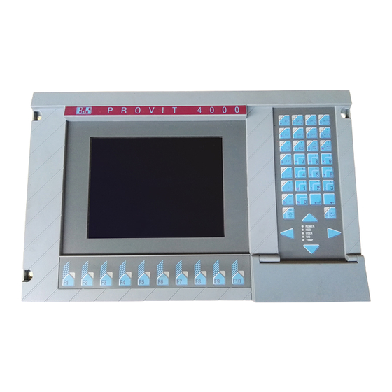
PROVIT 4000
USER'S MANUAL
Version:
Model No.: MAPRV4000-E
®
ARCNET
is a registered trademark of the Datapoint Corp.
®
ETHERNET
is a registered trademark of the XEROX Corp.
®
IBM
is a registered trademark of the International Business Machines Corp.
®
MS-DOS
is a registered trademark of the Microsoft Corp.
®
Windows
is a registered trademark of the Microsoft Corp.
®
OS-2
is a registered trademark of the International Business Machines Corp.
®
PROFIBUS
is a registered trademark of the PROFIBUS User Organisation
2.0 (December 1995)
1
Advertisement
Table of Contents

Related Manuals for B&R PROVIT 4000


Summary of Contents for B&R PROVIT 4000
- Page 1 PROVIT 4000 USER'S MANUAL Version: 2.0 (December 1995) Model No.: MAPRV4000-E ® ARCNET is a registered trademark of the Datapoint Corp. ® ETHERNET is a registered trademark of the XEROX Corp. ® is a registered trademark of the International Business Machines Corp.
- Page 2 We reserve the right to change the contents of this manual without warning. The information contained herein is believed to be accurate as of the date of publication, however, Bernecker and Rainer Industrie-Elektronik Ges.m.b.H. makes no warranty, expressed or implied, with regards to the products or the documentation contained within this book.
- Page 3 TABLE OF CONTENTS...
-
Page 5: Table Of Contents
TABLE OF CONTENTS 1. General Information ........................... 9 1.1 General Information ......................... 11 1.2 PROVIT 4000 Industrial PC ......................12 1.3 Operating System ..........................14 1.4 Documentation ..........................14 1.5 Model Numbers ..........................15 2. Start-up ..............................17 2.1 Unpacking ............................19 2.2 Checking the Delivery ........................ - Page 6 4.3 Controller ............................41 4.3.1 Technical Data ........................41 4.3.2 Motherboard ........................... 42 4.3.3 ISA Bus ..........................42 4.3.4 Power Supply ......................... 43 4.3.5 Disk Drive ..........................44 4.3.6 Fan ............................44 4.3.7 Ground Connection ........................ 45 4.3.8 VGA Controller ........................45 4.3.9 CAN Bus ..........................
- Page 7 7.2.2 Standard or Special Keypad Modules ..................76 7.3 Standard Keypad Modules ......................77 7.3.1 Connection to the PROVIT 4000 or Other Keypad Modules ..........77 7.3.2 Relationship Between Keypad Module and Display Unit ............78 7.3.3 Keypad Module Cable - 90 cm ....................79 7.3.4 Keypad Module 16 Keys ......................
-
Page 9: General Information
SECTION 1 GENERAL INFORMATION... -
Page 11: General Information
1.1 GENERAL INFORMATION PROVIT 4000 is an Industrial PC that distinguishes itself with its high capacity to serve in an industrial environment, functionality and flexibility. Capacity to Serve in an Industrial Environment TFT/LCD Displays Scratch resistant, anti-reflection safety glass Front is dust and water resistant in compliance with the IP54 (NEMA 12) standard... -
Page 12: Provit 4000 Industrial Pc
Can be delivered with a memory capacity of ≥ 120 MBytes or ≥ 340 MBytes • Power Cable • Power cable with connector that can be screwed onto PROVIT 4000 • Can be delivered with grounded plug or open cable end (for international connections) - Page 13 Accessories • Replacement filter • Cover plate for use without display unit • Legend sheet templates • Accessory pack (screws, washers, ...) • IBM AT enhanced keyboard (19") • PS2 keyboard adapter • Memory expansions • PROFIBUS card • Serial interface card •...
-
Page 14: Operating System
Several operating systems can be used because of the 100 percent compatibility to the IBM AT Standard. The MS-DOS operating system can be obtained from B&R on request in German or English. When ordering the PROVIT 4000 Industrial PC as a set, you can specify if MS-DOS should be pre-installed: Model Number for Pre-installaion: 5A4000.00... -
Page 15: Model Numbers
Power Cable with Plug - PROVIT 3030/4000 9A0001.01 Power Cable without Plug - PROVIT 3030/4000 9A0001.02 Replacement Filters for Fan (10 pack) 5A4001.01 Cover Plate - PROVIT 4000 5A4002.01 Accessory Pack - PROVIT 4000 5A4003.01 Legend Sheet Templates - PROVIT 4000 5A4003.02... - Page 16 RS232 ISA Card 5A1102.00-090 CENTRONICS Cable 1.8 m 9A0005.01 MS-DOS German 9S0000.01-010 MS-DOS English 9S0000.01-020 Pre-installation PROVIT 4000 5A4000.00 PROVIT MKEY Dev Kit - Modular Key Blocks 5S0001.02-090 Touch Screen Utilities 5S0003.01-090 PROVIT PC Card Utilities - Phoenix PC Card Manager 5S0002.01-020 Legend Sheet Templates PANELWARE (blue) 4A0005.00-000...
-
Page 17: Start-Up
SECTION 2 START-UP... -
Page 19: Unpacking
2.1 UNPACKING 1. Open carton 2. Remove the package with documentation and accessories 3. Remove the PROVIT 4000 together with the packing material and place on a flat surface 4. Carefully remove all packing material 2.2 CHECKING THE DELIVERY The packing material used for the PROVIT 4000 Industrial PC is an appropriate safeguard against damage during normal transport. -
Page 20: Before Power-On
90 - 260 VAC. The PROVIT 4000 Industrial PC can be operated with a supply voltage of 230 VAC (Europe) or 115 VAC (USA). The voltage selector setting must correspond with the supply voltage to be connected. -
Page 21: Provit 4000 Configuration
2.4 PROVIT 4000 CONFIGURATION The configuration of the PROVIT 4000 Industrial PC is carried out with the help of BIOS Setup. Only the standard keyboard driver is provided in BIOS Setup. 2.4.1 OPERATION WITH ONE HARD DISK 1) Pull the power plug. -
Page 22: Operation With Two Hard Disks
2.4.2 OPERATION WITH TWO HARD DISKS 1) Pull the power plug. 2) Insert hard disk 1 in the master slot (see Section "4.4 Hard Disk"). The drive designation is c: 3) Insert hard disk 2 in the slave slot. The drive designation is d: 4) Reinsert power plug. -
Page 23: Pentium Setup
2.4.3 PENTIUM SETUP The controller 5C4000.04 is equipped with a Pentium processor. The following note must be adhered to: The internal interfaces are not allowed to be enabled. The interfaces are set to "disable" by B&R as a default (in BIOS Setup: "Peripheral Configuration"). -
Page 24: Hard Disk Duplication (Ms-Dos)
2.5 HARD DISK DUPLICATION (MS-DOS) The PROVIT 4000 Industrial PC offers hard disk duplication as a feature for mass produce machines. The contents of a hard disk (source) is copied to a second hard disk (target). All of the files and data on the source hard disk that are necessary for the operation of the system as well as the operating system are copied to the destination hard disk. -
Page 25: Installation
SECTION 3 INSTALLATION... -
Page 27: 19" Rack Installation
P R O V I T 4 0 0 0 POWER USER TEMP. Installation: Insert cage nuts into the 19" rack. Place PROVIT 4000 housing in rack. Fasten the unit to the rack with the hardware provided. Place the screw covers over the screws. -
Page 28: Door Mount Installation
Four M6 screws Four M6 washers Four lock washers Four M6 nuts Make sure that the material in which the unit is to be mounted is strong enough. The PROVIT 4000 weights approx. 12 kg. INSTALLATION CUTOUT 465.1 mm (18 5/16 in.) 450 mm (17 3/4 in.) -
Page 29: Screw Covers
3.4 AIR CIRCULATION Proper air circulation is important for the PROVIT 4000. The unit has a fan on the right side of the housing. There are air vents on the left and right sides of the housing. The fan and the air vents are not to be blocked! -
Page 31: Device Description
SECTION 4 DEVICE DESCRIPTION... -
Page 33: Measurements
4.1 MEASUREMENTS P R O V I T 4 0 0 0 POWER USER TEMP. 465mm(18 5/16in) 188mm(7 7/16in) 38mm 483mm(19in) (1 1/2in) (11/32 in) 59mm 10.8mm (2 5/16in) 395.8mm(15 9/16in) (7/16in) 33.2mm (1 5/16in) NOTE: The cutout measurements for door mount installation are given in section "3.2 Door Mount Installation". -
Page 34: Display Unit
4.2 DISPLAY UNIT 4.2.1 DISPLAY There are four different display types: Model Number 5D4000.01 5D4000.03 5D4000.04 5D4000.05 Display Type TFT color, 256 colors, LCD STN color, 256 colors, LCD monochrome, 16 grey shades, TFT color, 256 colors, CFL back lit CFL back lit CFL back lit CFL back lit... -
Page 35: Keyboard
Contrast for the LCD Display: The contrast on the LCD display can be adjusted. The adjustment is made with the two shift keys and the cursor keys [↑] and [↓]. The shift keys must be pressed at the same time and the contrast is adjusted with the respective cursor key. Shift Keys: Press both at the same time 4.2.2 KEYBOARD... - Page 36 Default Key Assignments The built-in matrix keyboard is already assigned a key code when delivered. There are three different country codes in all saved on the unit. You can select between German, English and international according to your requirements. This effects characters such as umlauts, special characters etc. The international code is assigned as default.
-
Page 37: Key Labelling
Key Legend Strips Two keypad legend sheet templates are delivered with the PROVIT 4000. They can be printed on with a laser printer and cut using the marks provided. The strips allow for the key LEDs. Legend sheets templates are available as replacement accessories (see section "8.6 Accessories"). -
Page 38: Disk Drive Cover
4.2.6 DISK DRIVE COVER The disk drive cover protects the built-in 3.5" disk drive from dust and water (IP54 / NEMA 12). 4.2.7 RESET BUTTON The reset button is found under the disk drive cover. The button is best actuated with a small screw driver. Pressing the reset button causes a reset with memory test (cold start). -
Page 39: Replacing The Display Unit
4.2.9 REPLACING THE DISPLAY UNIT Only replace the display unit with the power cable unplugged! Remove the four M5 nuts shown below Remove the display unit Insert new display unit Replace and tighten the four M5 nuts Remove Nuts Remove Nuts... -
Page 40: Touch Screen Information
4.2.10 TOUCH SCREEN INFORMATION The display unit is delivered complete with the respective driver for the operation of the Touch Screen. According to the revision of the display unit, either a Dynapro or Elotouch touch screen is used. If a display unit with an integrated touch screen is used, the COM2 interface is no longer at your disposal! This interface is automatically reserved internally for the operation of the touch screen . -
Page 41: Controller
4.3 CONTROLLER 4.3.1 TECHNICAL DATA Model Number 5C4000.01 5C4000.02 5C4000.03 5C4000.04 Processor 486SLC2-25/50 486SLC2-33/66 486DX4-100 Pentium-100 Internal Cache 16 KBytes 16 KBytes 8 KBytes 16 KBytes External Cache 64 KBytes 256 KBytes 256 KBytes Working Memory 4 MBytes 4 MBytes 8 MBytes 8 MBytes (DRAM) -
Page 42: Motherboard
Expanding working memory is described in section "8.1 Memory Expansion". 4.3.3 ISA BUS The PROVIT 4000 Industrial PC provides a 16 bit ISA bus with four slots. Two long and two short cards can be inserted. Card Installation / Removal: In order to get to the bus, the housing cover must be removed. -
Page 43: Power Supply
90 - 260 VAC. The PROVIT 4000 Industrial PC can be operated with a supply voltage of 230 VAC (Europe) or 115 VAC (USA). The position of the voltage selector switch must be checked before power is connected. -
Page 44: Disk Drive
4.3.5 DISK DRIVE The PROVIT 4000 Industrial PC provides a 3.5" disk drive that can be accessed from the front. Both DD diskettes (720 KByte) or HD diskettes (1.44 MByte) can be used. The disk drive is protected against dust and water (IP54 / NEMA 12) with a cover. -
Page 45: Ground Connection
4.3.7 GROUND CONNECTION An additional ground connection is to be made to the ground connector on the left side of the PROVIT 4000 Industrial PC. 4.3.8 VGA CONTROLLER Technical Data: Memory 0.5 MByte RAM Resolution 640 * 480 pixels Display Control... -
Page 46: Can Bus
4.3.9 CAN BUS The CAN bus can be found on the left side of the PROVIT 4000 Industrial PC. An INTEL 82527 processor is used as CAN controller. The CAN bus is supplied with power either internally or externally. The selection is made with the help of a switch. -
Page 47: Serial Interface
4.3.10 SERIAL INTERFACE The serial interfaces COM1 to COM4 can be found on the left side of the PROVIT 4000 Industrial PC. COM1 COM2 9 Pin D-Type RS232 interface RS232 interface Connector (M) electrically isolated not electrically isolated up to 115 kBaud... -
Page 48: Parallel Interface Lpt1
4.3.11 PARALLEL INTERFACE LPT1 The parallel interface LPT1 can be found on the left side of the PROVIT 4000 Industrial PC. It is a 25 pin D-type connector (F). Assignment Assignment 25 Pin D-Type Data Strobe Autofeed Connector (F) Data 0... -
Page 49: Keypad Connection
4.3.13 KEYPAD CONNECTION The sockets for the connection of up to seven keypad modules can be found on the left side of the PROVIT 4000 Industrial PC. The keypad modules work in parallel to the built-in matrix keypad and to an optional external enhanced AT keyboard. -
Page 50: Enhanced At Keyboard Connection
The connection of an external enhanced AT keyboard can be made via a 5 pin DIN connector on left side of the PROVIT 4000 Industrial PC. The external AT keyboard works in parallel to the built-in matrix keyboard and to optional keypad modules. -
Page 51: Jumper
4.3.19 JUMPER The jumpers are used for interface, drive and the display settings. There are two different jumper configurations dependent on the controller revision: Controller Rev. < 10.xx Controller Rev. ≥ 10.xx Jumper configuration for controllers with a rev. < 10.xx: Seven rows of jumpers can be found on the top edge of the I/O board. - Page 52 Jumpers in Row 1 Jumper Function disable CAN-IC (Attention: In spite of being disabled, the CAN address area is not freed!) CAN IRQ15 CAN IRQ11 CAN IRQ10 (default) CAN IRQ12 Jumpers in Row 2 Jumper Function disable COM1 (address freed) disable COM2 (address freed) disable HDD...
- Page 53 Jumper configuration for controllers with a rev. ≥ 10.xx: Nine rows of jumpers can be found on the top edge of the I/O board. The housing cover has to be removed to access the jumpers. The cover can be removed by loosening the two screws shown below. Remove Screws The jumpers are described in the table on the next page.
- Page 54 Disable open CAN Controller activated (I/O addresses see section "5.1 B&R I/O Area") inserted CAN Controller deactivated (I/O area free for e.g. ISA cards) IRQ10 open IRQ10 available for ISA cards inserted IRQ10 used for CAN Controller COM1 Disable open COM UART activated (I/O addresses see section "6.1.2 I/O Address Assignments") inserted COM UART deactivated (I/O area free for e.g.
-
Page 55: Interact Hardware Key
4.3.20 INTERACT HARDWARE KEY The INTERACT hardware key can be used in all PROVIT 4000 Industrial PCs. The controller revision must be taken into consideration: Controller INTERACT Hardware Key Rev. < 10.xx For controllers with a rev. < 10.xx, the INTERACT hardware key cannot operate on LPT1 alone. The operation of an INTERACT hardware key internally in the device in conjunction with the LPT1 parallel interface is not supported. - Page 56 When seen from the front, the key slot for the INTERACT hardware key is on the left side of the I/O board. Because of the mechanical characteristics of the INTERACT hardware key, reversing the polarity is not possible. A battery is not allowed to be inserted in the key slot for the INTERACT hardware key! Slot for INTERACT Hardware Key...
-
Page 57: Operation Of The Controllers Without The Display Unit
4.3.21 OPERATION OF THE CONTROLLERS WITHOUT THE DISPLAY UNIT If required, the controller can also be operated without a display unit. A cover plate (5A4002.01) is installed instead of the display unit. The operation of the keypad modules is no longer possible. Make sure to use the proper jumper settings (see section "4.3.19 Jumper"): Controller with rev. - Page 58 In order to keep the disk drive from sticking out, it can be set further back in the housing: Remove the four screws shown below which can be found on the bottom of the PROVIT 4000 Slide the disk drive backwards...
-
Page 59: Hard Disk
4.4 HARD DISK Two hard disks can be inserted in the hard disk frame of the PROVIT 4000 Industrial PC. Two hard disks are available from B&R with different memory capacities: Model Number Hard Disk Memory Capacity ≥ 120 MBytes 5A4000.01... - Page 60 The hard disk frame can be found on the left side of the I/O board. Two hard disks can be installed (see below for drive description). The hard disks are held in place with adhesive foam on the housing cover. Slot for Drive d: (Slave)
-
Page 61: Power Cable
4.5 POWER CABLE The power cable is not contained with the delivery of the PROVIT 4000 Controller. It must be ordered separately. The cable is approx. 1.8 m long. Model Number Power Cable 9A0001.01 Cable with power plug 9A0001.02 Cable without power plug The connection to the device is a screw on plug. -
Page 63: Software
SECTION 5 SOFTWARE... -
Page 65: B&R I/O Area
5.1 B&R I/O AREA I/O Address Function I/O Address Function 300h LED 0 305h LED F9 LED 1 LED F10 LED 2 reserved LED 3 reserved LED 4 reserved LED 5 reserved LED 6 reserved LED 7 reserved 301h LED 8 306h reserved LED 9... -
Page 66: Key Illumination
5.2 KEY ILLUMINATION 5.2.1 FUNCTION KEY LEDS I/O Address 300h 300h 300h 300h 300h 300h 300h 300h 301h 301h 301h 301h 301h 301h 301h 301h 5.2.2 SOFTKEY KEY LEDS I/O Address 304h 304h 304h 304h 304h 304h 304h 304h 305h 305h... -
Page 67: User Led
5.3 USER LED The User LED is controlled with the I/O address 306h, bit 7. 5.4 RELAY OUTPUT Setting / resetting the relay output is done with I/O address 306h, bit 6. 5.5 TEMPERATURE MONITORING The temperature is monitored at three measurement points. The three points are: CPU (processor) Display Power Supply... -
Page 69: Memory Assignments
SECTION 6 MEMORY ASSIGNMENTS... -
Page 71: Memory Assignments
6.1 MEMORY ASSIGNMENTS 6.1.1 RAM - ADDRESS ASSIGNMENTS RAM Address Function 000000h - 0003FFh Interrupt Vectors 000400h - 09FFFFh MS-DOS Program Area 0A0000h - 0AFFFFh VGA - Graphics 0B8000h - 0BBFFFh VGA - Text Mode 0C0000h - 0C7FFFh VGA - BIOS 0C8000h - 0EFFFFh free 0F0000h - 0FFFFFh... -
Page 72: Interrupts
6.1.3 INTERRUPTS Controller with Rev. ≥ ≥ ≥ ≥ ≥ 10.xx IRQ No. Controller with Rev. < 10.xx IRQ0 System Timer System Timer IRQ1 Keyboard Keyboard IRQ2 Daisy Chained with Interrupt Controller 2 Daisy Chained with Interrupt Controller 2 IRQ3 COM2 or COM4 COM2, COM4 or free IRQ4... -
Page 73: Keypad Modules
SECTION 7 KEYPAD MODULES... -
Page 75: Overview
7.1 OVERVIEW 16 Keys Dummy Module Keys: 16 Keys: none LEDs: 16 LEDs: none 12 + 4 Keys E-Stop Keys: 16 E-Stop Button LEDs: 4 STOP Key Switch 8 Keys Keys: 8 Key Switch: 1 LEDs: 4 On/Off Switch: 1 Label Fields: 1 Start / Stop 4 Keys... -
Page 76: General Information
Special Keypad Modules are identical to the rest of the keypad modules regarding their design. An electrical connection with a PROVIT 4000 or standard keypad module is not possible. They are to be wired by an electrician according to their function (e.g. connecting the E-Stop button to the emergency... -
Page 77: Standard Keypad Modules
7.3.1 CONNECTION TO THE PROVIT 4000 OR OTHER KEYPAD MODULES All standard keypad modules can be connected to the PROVIT 4000 or another keypad module with a short connection cable. There are two female connectors provided on the module for this purpose. -
Page 78: Relationship Between Keypad Module And Display Unit
The operation of the keypad modules is only possible if a display unit is installed. If a display unit with a rev. < 20.16 is used, not all keypad modules can be connected to the PROVIT 4000. The following table contains an overview:... -
Page 79: Keypad Module Cable - 90 Cm
Model Number: 9A0007.01 It can only be connected between the PROVIT 4000 and the first keypad module. The standard keypad module cable (13 cm long) is to be used for all other keypad modules. The display unit must have a rev. ≥ 20.16. Only keypad modules with the following model... -
Page 80: Keypad Module 16 Keys
7.3.4 KEYPAD MODULE 16 KEYS 35 mm (1 3/8 in) 96 mm (3 3/4 in) Model Number 4E0011.01-090 Number of Keys 16 Short Stroke Keys Number of LEDs 16 (yellow) Labelling Can be labelled by the user Temperature Range Operation 0 to 50 °C (32 to 122 °F) Storage... -
Page 81: Keypad Module 12+4 Keys
7.3.5 KEYPAD MODULE 12+4 KEYS 35 mm (1 3/8 in) 96 mm (3 3/4 in) Model Number 4E0021.01-090 Number of Keys 16 Short Stroke Keys Number of LEDs 4 (yellow) Labelling 12 keys are labelled as number blocks 4 keys can be labelled by the user Temperature Range Operation 0 to 50 °C... -
Page 82: Keypad Module 8 Keys
7.3.6 KEYPAD MODULE 8 KEYS 35 mm (1 3/8 in) 96 mm (3 3/4 in) Model Number 4E0031.01-090 Number of Keys 8 Short Stroke Keys Number of LEDs 4 (yellow) Labelling Can be labelled by the user Label Fields One field for additional information Temperature Range Operation 0 to 50 °C... -
Page 83: Keypad Module 4 Keys
7.3.7 KEYPAD MODULE 4 KEYS 35 mm (1 3/8 in) 96 mm (3 3/4 in) Model Number 4E0041.01-090 Number of Keys 4 Short Stroke Keys Number of LEDs 4 (yellow) Labelling Can be labelled by the user Label Fields Four fields for additional information Temperature Range Operation 0 to 50 °C... -
Page 84: Special Keypad Modules
7.4 SPECIAL KEYPAD MODULES 7.4.1 DUMMY MODULE 35 mm (1 3/8 in) 96 mm (3 3/4 in) Model Number 4E0050.01-090 Number of Keys none Number of LEDs none Temperature Range Operation 0 to 50 °C (32 to 122 °F) Storage -20 to 60 °C (-4 to 140 °F) Relative Humidity... -
Page 85: E-Stop Button
7.4.2 E-STOP BUTTON 51 mm (2 in) STOP 35 mm (1 3/8 in) 96 mm (3 3/4 in) Model Number 4E0060.01-090 Number of Buttons 1 E-Stop Button Temperature Range Operation 0 to 50 °C (32 to 122 °F) Storage -20 to 60 °C (-4 to 140 °F) Relative Humidity Operation... -
Page 86: Key Switch
7.4.3 KEY SWITCH 60mm (2 3/8 in) 35 mm (1 3/8 in) 96 mm (3 3/4 in) Model Number 4E0070.01-090 Number of Switches 1 Key Switch 1 On/Off Switch Temperature Range Operation 0 to 50 °C (32 to 122 °F) Storage -20 to 60 °C (-4 to 140 °F) -
Page 87: Start/Stop
7.4.4 START/STOP 60 mm (2 3/8 in) START STOP 35mm (1 3/8 in) 96 mm (3 3/4 in) Model Number 4E0080.01-090 Number of Keys 2 Keys (labelled START or STOP) Temperature Range Operation 0 to 50 °C (32 to 122 °F) Storage -20 to 60 °C (-4 to 140 °F) -
Page 88: Accessories
Accessories are delivered with each keypad module. They are packed together with the module. Accessories Amount Standard Special Keypad Module Keypad Module Connection Elements Cable Covers Keypad Module Cable (connection to PROVIT 4000 or keypad module) Clamps Mounting Bolt Pins... -
Page 89: Options And Accessories
SECTION 8 OPTIONS AND ACCESSORIES... -
Page 91: Memory Expansion
8.1 MEMORY EXPANSION The PROVIT 4000 Industrial PC is equipped with SIMM slots for SIMM memory modules. The PROVIT 4000 Industrial PCs are standardly equipped with the following amount of working memory: Model Number 5C4000.01 5C4000.02 5C4000.03 5C4000.04 Working Memory... - Page 92 Remove the 5 screws shown below View: Remove Screws Side Back View: View: Remove Screws Remove Screws Front View: Remove Screws...
- Page 93 Pull controller out A two pin plug is found on the bus board. It concerns the temperature sensor for the power supply. This plug must be removed. Remove Plug Remove the three screws shown below Remove Screws The motherboard must be folded back to access the SIMMs Change the SIMMs as described in the motherboard description The controller is reassembled in the opposite order...
-
Page 94: Centronics/Online Converter
A CENTRONICS/Online Converter (model no. BRKAOL5-1) can be used to program the PLC processors of the B&R MINICONTROL or MULTICONTROL PLC systems. The CENTRONICS/Online Converter is con- nected to the LPT1 parallel interface of the PROVIT 4000. It allows a PLC processor to be programed. 8.3 PROFIBUS NETWORK CARD... -
Page 95: Index
INDEX... - Page 97 Accessories Delivery Contents Keypad Modules Digital Output 48, 67 PROVIT 4000 15, 16, 94 Disk Drive Accessories 15, 16 Disk Drive Cover Air Circulation Display Application Keys Brightness ARCNET Network Card Contrast (LCD) AT Keyboard (enhanced) 16, 50 Jumper Technical Data...
- Page 98 Power Cable 20, 43, 61 Keypad Module Cable (90 cm) Power Plug 20, 61 Measurements and Remarks Power Supply Overview Processor Start/Stop PROFIBUS Network Card 16, 94 Protective Circuit for Relay Output PROVIT 4000 Industrial PC PROVIT MKEY Utilities 16, 35...
- Page 99 Relay Output 48, 67 Unpacking Replacement Filter User LED Reset Button RS232 Interface Card Interfaces VGA Controller RS485 Interface Voltage Selector 20, 43 Voltage Selector Switch 20, 43 Screw Covers SIMM Memory Modules Watchdog Slots Weight Softkey Keys Working Memory 41, 91 Start-up Start/Stop (special keypad module)
Need help?
Do you have a question about the PROVIT 4000 and is the answer not in the manual?
Questions and answers