Table of Contents
Advertisement
Quick Links
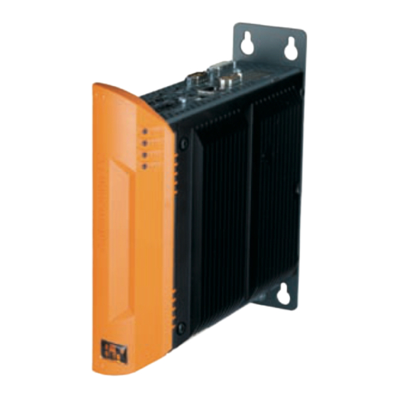
Automation PC 510
All information contained in this manual is current as of its creation/publication. We reserve the right to change
the contents of this manual without warning. The information contained herein is believed to be accurate as of
the date of publication; however, Bernecker + Rainer Industrie-Elektronik Ges.m.b.H. makes no warranty, ex-
pressed or implied, with regard to the products or the documentation contained within this book. Bernecker + Rain-
er Industrie-Elektronik Ges.m.b.H. shall not be liable in the event of incidental or consequential damages in con-
nection with or arising from the furnishing, performance or use of these products. The software names, hardware
names, and trademarks used in this document are registered by the respective companies.
User's Manual
Version: 1.01 (June 2012)
Order no.: MAAPC510-GER
1
Advertisement
Table of Contents

Related Manuals for B&R Automation PC 510


Summary of Contents for B&R Automation PC 510
- Page 1 Automation PC 510 User's Manual Version: 1.01 (June 2012) Order no.: MAAPC510-GER All information contained in this manual is current as of its creation/publication. We reserve the right to change the contents of this manual without warning. The information contained herein is believed to be accurate as of the date of publication; however, Bernecker + Rainer Industrie-Elektronik Ges.m.b.H. makes no warranty, ex- pressed or implied, with regard to the products or the documentation contained within this book. Bernecker + Rain- er Industrie-Elektronik Ges.m.b.H. shall not be liable in the event of incidental or consequential damages in con- nection with or arising from the furnishing, performance or use of these products. The software names, hardware names, and trademarks used in this document are registered by the respective companies.
- Page 2 Chapter 1: General information Chapter 2: Technical data Chapter 3: Commissioning Chapter 4: Software Chapter 5: Accessories Chapter 6: Maintenance / Service Appendix A...
-
Page 3: Table Of Contents
3.1.1 5PC510.SX01-00...........................32 3.2 US15W - CPU boards..........................36 3.2.1 General information..........................36 3.2.2 Order data............................. 36 3.2.3 Technical data............................36 3.3 Main memory............................37 3.3.1 Order data............................. 37 3.3.2 Technical data............................37 3.4 Interface boards............................38 Automation PC 510 User's Manual V 1.01... - Page 4 1.5.7 SDIO configuration..........................98 1.5.8 ACPI table/features control........................99 1.5.9 PCI Express root port 1........................99 1.5.10 PCI Express root port 2........................102 1.5.11 Console redirection.......................... 103 1.6 Security..............................106 1.6.1 Set supervisor password........................107 1.6.2 Set user password..........................108 1.7 Power..............................109 1.7.1 Advanced CPU control........................110 1.7.2 Platform power management......................113 1.8 Boot................................. 114 1.8.1 Legacy..............................115 1.9 Exit................................119 Automation PC 510 User's Manual V 1.01...
- Page 5 7 Windows CE..............................137 7.1 General information..........................137 7.2 Order data..............................137 7.3 Overview..............................137 7.4 Windows CE 6.0 features........................137 7.5 Requirements............................138 7.6 Installation..............................138 7.7 B&R Embedded OS Installer........................138 8 Automation Runtime............................. 139 8.1 General information..........................139 Automation PC 510 User's Manual V 1.01...
- Page 6 5 USB flash drive.............................159 5.1 5MMUSB.2048-01............................ 159 5.1.1 General information..........................159 5.1.2 Order data............................159 5.1.3 Technical data............................. 159 5.1.4 Temperature humidity diagram......................160 6 Cables................................161 6.1 DVI cables...............................161 6.1.1 5CADVI.0xxx-00..........................161 6.2 SDL cables..............................164 Automation PC 510 User's Manual V 1.01...
- Page 7 6.5.1 5CASDL.0xx0-13..........................173 6.6 USB cables............................. 177 6.6.1 5CAUSB.00xx-00..........................177 6.7 RS232 cables............................178 6.7.1 9A0014.xx............................178 Chapter 6 Maintenance / Service................180 1 Replacing the CompactFlash card....................... 180 Appendix A Anhang A [v1.7].................. 181 1 Abbreviations..............................181 Automation PC 510 User's Manual V 1.01...
-
Page 8: Chapter 1 General Information
Chapter 6 "Maintenance / Service" updated. • Terminal block 0TB1208.3100 (interface board plug) updated in Chapter 5 " Accessories". • New CompactFlash cards 5CFCRD.xxxx-06 updated in Chapter 5 " Accessories". CompactFlash cards • 5CFCRD.xxxx-04 discontinued. Interface board 5PP5IF.FETH-00 updated on page 5PP5IF.FETH-00. • Hard disk 5MMHDD.0250-00 updated on page 5MMHDD.0250-00. • Sections "Temperature specifications" on page 18, " Humidity specifications" on page 20 and "Pow- • er management" on page 21 updated in Chapter 2 "Technical data". Section " Mounting orientation" on page 62 updated in Chapter 3 "Commissioning". • 1.01 18-Jun-12 Section "Cable lengths and resolutions for SDL transfer" on page 54 updated. • Automation PC 510 User's Manual V 1.01... -
Page 9: 2 Safety Guidelines
• Ensure a minimum distance of 10 cm from monitors and TV sets. • Measurement devices and equipment must be grounded. • Measurement probes on potential-free measurement devices must be discharged on sufficiently grounded surfaces before taking measurements. Individual components • ESD protective measures for individual components are thoroughly integrated at B&R (conductive floors, footwear, arm bands, etc.). • These increased ESD protective measures for individual components are not necessary for customers handling B&R products. 2.3 Policies and procedures Electronic devices are never completely failsafe. In the event of a failure on the programmable control system, operating/monitoring device or uninterruptible power supply, the user is responsible for ensuring that other devices that may be connected, e.g. motors, are brought to a safe state. Automation PC 510 User's Manual V 1.01... -
Page 10: Transport And Storage
The presence of aggressive gases can also lead to malfunctions. When combined with high temperature and humidity, aggressive gases – e.g. with sulfur, nitrogen and chlorine components – can induce chemical reactions that can damage electronic components very quickly. Signs of the presence of aggressive gases are blackened copper surfaces and cable ends on existing equipment. For operation in dusty or humid conditions, correctly installed (cutout installation) operating/monitoring devices like the Automation Panel or Power Panel are protected on the front side. The rear side of all devices must be protected from dust and humidity and cleaned at suitable intervals. 2.6.3 Programs, viruses and dangerous programs This system is subject to potential risk each time data is exchanged or software is installed from a data medium (e.g. diskette, CD-ROM, USB flash drive, etc.), a network connection or the Internet. The user is responsible for assessing these dangers, implementing preventive measures such as virus protection programs, firewalls, etc. and making sure that software is only obtained from trusted sources. Automation PC 510 User's Manual V 1.01... -
Page 11: Environmentally Friendly
2.7.1 Separation of materials It is necessary to separate different materials so the device can undergo an environmentally friendly recycling process. Component Disposal Programmable logic controllers Electronics recycling Operating/monitoring devices Uninterruptible power supply Batteries & rechargeable batteries Cables Cardboard box / paper packaging Paper / cardboard recycling Plastic packaging Plastic recycling Table 1: Environmentally friendly separation of materials Disposal must comply with applicable legal regulations. Automation PC 510 User's Manual V 1.01... -
Page 12: 3 Organization Of Safety Notices
Caution! Disregarding safety regulations and notices can result in severe injury or substantial damage to equipment. Warning! Disregarding safety guidelines and notices can result in injury or damage to equipment. Information: Important information for preventing errors. Table 2: Organization of safety notices 4 Guidelines European dimension standards apply to all dimension diagrams in this document. All dimensions are specified in mm. Nominal measurement area General tolerance according to DIN ISO 2768 medium Up to 6 mm ±0.1 mm For 6 to 30 mm ±0.2 mm For 30 to 120 mm ±0.3 mm For 120 to 400 mm ±0.5 mm For 400 to 1000 mm ±0.8 mm Table 3: Nominal measurement areas Automation PC 510 User's Manual V 1.01... -
Page 13: 5 Overview
RS232 cables 9A0014.02 RS232 extension cable for remote operating of a display unit with touch screen, 1.8 m. 9A0014.05 RS232 extension cable for remote operating of a display unit with touch screen, 5 m. 9A0014.10 RS232 extension cable for remote operating of a display unit with touch screen, 10 m. SDL cables 5CASDL.0018-00 SDL cable, 1.8 m. 5CASDL.0050-00 SDL cable, 5 m. 5CASDL.0100-00 SDL cable, 10 m. 5CASDL.0150-00 SDL cable, 15 m. 5CASDL.0200-00 SDL cable, 20 m. 5CASDL.0250-00 SDL cable, 25 m. 5CASDL.0300-00 SDL cable, 30 m. SDL cables: 45° connectors 5CASDL.0018-01 SDL cable; 45° connector, 1.8 m. 5CASDL.0050-01 SDL cable; 45° connector, 5 m. 5CASDL.0100-01 SDL cable; 45° connector, 10 m. Automation PC 510 User's Manual V 1.01... - Page 14 Microsoft OEM Windows CE 6.0 Professional, English; for APC510; please order CompactFlash separately (minimum 128 MB). Windows Embedded Standard 7 5SWWI7.0537-ENG Microsoft OEM Windows Embedded Standard 7 32-bit, English; for APC510; please order CompactFlash sep- arately (minimum 8 GB). 5SWWI7.0737-MUL Microsoft OEM Windows Embedded Standard 7 Premium 32-bit, multilanguage; for APC510; please order CompactFlash separately (minimum 8 GB). Windows XP Professional 5SWWXP.0600-ENG Microsoft OEM Windows XP Professional Service Pack 3, CD, English. Only available with a B&R device. 5SWWXP.0600-GER Microsoft OEM Windows XP Professional Service Pack 3, CD, German. Only available with a device. 5SWWXP.0600-MUL Microsoft OEM Windows XP Professional Service Pack 3, CD, multilanguage. Only available with a B&R device. Automation PC 510 User's Manual V 1.01...
-
Page 15: Chapter 2 Technical Data
• 1x Ethernet 10/100/1000 Mbit/s • Optional interface boards • 1 CompactFlash slot (type I) • 24 VDC supply voltage • Operation without fan or heat sink • BIOS (Insyde) • Real-time clock (RTC, battery-backed) 1.2 System components / configuration The APC510 system can be assembled to meet individual requirements and operating conditions. The following components are absolutely essential for operation: • System unit • CPU board • Main memory • I/O board • Drive (mass storage device such as CompactFlash card) for the operating system • Power connector (terminal block) Automation PC 510 User's Manual V 1.01... -
Page 16: Configuration - Base System
CPU board - Main memory CPU board Select one 5PP5CP.US15-00 - 1100 MHz 5PP5CP.US15-01 - 1330 MHz 5PP5CP.US15-02 - 1600 MHz Main memory Select one 5MMDDR.0512-01 5MMDDR.1024-01 5MMDDR.2048-01 I/O board Select one 5PP5IO.GMAC-00 Image 1: Configuration - Base system Automation PC 510 User's Manual V 1.01... -
Page 17: Configuration - Software And Accessories
1A4601.06-T 5SWWI7.0300-MUL Automation Runtime Windows Embedded Standard 7 Windows Embedded Standard 2009 5SWWI7.0537-ENG 5SWWI7.0537-ENG 5SWWI7.0737-MUL Windows CE 6.0 5SWWCE.0837-ENG Terminal blocks Select 1 each Power connectors Interface board connection 0TB103.9 0TB1208.3100 0TB103.91 Image 2: Configuration - Software and accessories Automation PC 510 User's Manual V 1.01... -
Page 18: 2 Complete Device
Sensors monitor temperature values at various locations (USB ports, main memory) inside the APC510. These temperatures can be read in Microsoft Windows operating systems using the B&R Control Center or in Automa- tion Runtime using data points in Automation Studio. Image 3: Temperature sensor locations Position Measurement point for measurement Max. specified Ambient temperature of the processor (sensor integrated in the processor) 100°C: 5PP5CP.US15-00, 5PP5CP.US15-01 90°C: 5PP5CP.US15-02 Main memory Ambient temperature of the main memory (sensor integrated in the processor) 80°C Interfaces Temperature of the interfaces (sensor integrated next to the USB ports). 80°C Interface board Temperature of an interface board (sensor integrated on the interface board) Board-specific I/O board Temperature of an I/O board (sensor integrated on the I/O board) Board-specific Table 4: Temperature sensor locations The temperature measured approximates the immediate ambient temperature but may also be influenced by neighboring components. The B&R Control Center is included in the ADI driver, which is available in the Downloads section of the B&R website (www.br-automation.com). Automation PC 510 User's Manual V 1.01... -
Page 19: Temperature Monitoring
Technical data • Complete device 2.1.2 Temperature monitoring Sensors monitor temperature values in various places (CPU, interfaces, interface board, I/O board) inside the APC510. The locations of the temperature sensors can be seen in "Image 3: Temperature sensor locations" on page 18. The values listed in the table represent the defined maximum temperature for the respective measurement point. An alarm is not triggered if this temperature is exceeded. These temperatures can be read in BIOS or in approved Microsoft Windows operating system together with Automation Runtime and the B&R Control Center. The temperature measured approximates the immediate ambient temperature but may also be influenced by neighboring components. Automation PC 510 User's Manual V 1.01... -
Page 20: Humidity Specifications
5 to 90% 5 to 95% 5PP5IF.FETH-00 5 to 90% 5 to 95% 5PP5IF.FX2X-00 5 to 90% 5 to 95% 5PP5IF.FXCM-00 5 to 90% 5 to 95% I/O boards 5PP5IO.GMAC-00 5 to 90% 5 to 95% 5CFCRD.xxxx-06 CompactFlash cards 5CFCRD.xxxx-04 CompactFlash cards Accessories 5CFCRD.xxxx-03 CompactFlash cards 8 to 95% 8 to 95% 5MMUSB.2048-01 flash drive 10 to 90% 5 to 90% Table 5: Overview of humidity specifications for individual components Specifications correspond to non-condensing relative humidity. The listed specifications correspond to the relative humidity at an ambient temperature of 30°C. More detailed information about the specific temperature-dependent humidity values can be found in the technical data for the individual components. Automation PC 510 User's Manual V 1.01... -
Page 21: Power Management
The following block diagram illustrates the simplified structure of the supply voltage for system units. Supply voltage 15 V 24 V 15 V +24 VDC electrically isolated 3V3 standby Capacitors 15 V (for min. 10 ms) 5 V standby Power button on Image 4: Supply voltage for system units Description 15 V is generated from the supply voltage using a DC/DC converter. This electrically isolated 15 V supplies further DC/DC converters, which generate the remaining voltage. After the system is turned on (e.g. using the power button), the 3V3 and 5 V voltages are active on the system. Automation PC 510 User's Manual V 1.01... -
Page 22: Device Interfaces
COM RS232 Ethernet RS232/422/458 10/100/1000 USB1, USB2 USB4 USB3 Ground connection HDA sound Supply voltage +24 VDC Status LEDs Power button Reset button Ground connection CompactFlash Slot SD memory card Slot Battery Image 5: Overview of interfaces with an inserted I/O board Automation PC 510 User's Manual V 1.01... -
Page 23: Supply Voltage +24 Vdc
The pin's connection to the functional ground (pin 2) should be as short a path as possible (e.g. in the control cabinet). We recommend using the largest possible conductor cross section on the supply plug. The grounding connection is located on the bottom of APC510 systems. Ground connection Image 6: Ground connection The M4 self-locking nut can be used, for example, to fasten a copper strip that is built into the APC510 at a central grounding point in the control cabinet or system. The largest possible conductor cross section should be used (at least 2.5 mm²). Automation PC 510 User's Manual V 1.01... -
Page 24: Serial Interface Com1
Technical data • Complete device 2.4.3 Serial interface COM1 COM1 serial interface RS232 Type RS232, modem-capable, not electrically isolated UART 16550-compatible, 16-byte FIFO Transfer rate Max. 115 kBaud 9-pin DSUB plug Cable length Max. 15 meters assignment Table 7: Pinout - COM1 Automation PC 510 User's Manual V 1.01... -
Page 25: Ethernet (Eth)
100 Mbit/s 10 Mbit/s Orange 1000 Mbit/s Link LED Orange Link (Ethernet network Activity (blinking - da- connection available) ta transfer in progress) Table 8: Ethernet connection (ETH) Switching takes place automatically. The 10 Mbit/s transfer speed / connection is only present if the Link LED is also lit at the same time. Driver support A special driver is required in order to operate the Intel 82574 Ethernet controller. Drivers for approved operating systems are available in the Downloads area of the B&R website (www.br-automation.com). Information: Required drivers can only be downloaded from the B&R homepage, not from manufacturers' pages. Automation PC 510 User's Manual V 1.01... -
Page 26: Usb Ports (Usb1, Usb2)
EMC, cable routing, etc. USB1, USB2 ports Universal Serial Bus (USB1, USB2) Type USB 2.0 2x USB Type A, female Design Type A Transfer rate Low speed (1.5 Mbit/s), full speed (12 Mbit/s), high speed (480 Mbit/s) USB2 Current load USB1, USB2 Max. 1 A Cable length Max. 5 m (without hub) USB1 Table 9: USB1, USB2 ports The interfaces, etc. available on the device or module have been numbered as such for easy identification. This numbering can differ from that used by the particular operating system. Each USB port is secured with a maintenance-free "USB current-limiting circuit breaker" (max. 500 mA or 1 A). Automation PC 510 User's Manual V 1.01... -
Page 27: Battery
4 years Model number Short description Battery Batteries 0AC201.91 Lithium batteries, 4 pcs., 3 V / 950 mAh, button cell 4A0006.00-000 Lithium battery, 1 pc., 3 V / 950 mAh, button cell Table 10: Battery At 50°C, 8.5 μA for the components being supplied and a self-discharge of 40%. If an interface board with SRAM is installed, then the lifespan is reduced to 2½ years. Battery status evaluation The status of the battery is determined immediately after the device is started and subsequently checked by the system every 24 hours. During this measurement, the battery is subjected to a brief (approximately 1 second) load and then evaluated. Once determined, the battery status is displayed in BIOS (under OEM Features - CPU Board Features - CPU Board Monitor) and in the B&R Control Center (ADI driver); it can also be read in a customer application using the ADI library. Battery status Meaning The hardware or firmware being used is too old and does not support reading the battery status. GOOD Data buffering is provided. Data buffering is provided for approximately another 500 hours from the point when battery capacity is recognized as insufficient (BAD). Table 11: Meaning of the battery status Data buffering is provided for approximately another 500 hours from the point when battery capacity is recognized as insufficient. When replacing the battery, data is buffered for approximately 10 minutes by a gold leaf capacitor. Automation PC 510 User's Manual V 1.01... -
Page 28: Compactflash Slot
B&R CompactFlash 4096 MB 5CFCRD.8192-06 B&R CompactFlash 8192 MB 5CFCRD.016G-06 B&R CompactFlash 16 GB Table 12: CompactFlash slot Warning! Turn off power before inserting or removing the CompactFlash card! 2.4.8 SD memory card slot The SD memory card slot only supports SD memory cards, not SDHC cards. SD memory cards are only permitted for use as a mass storage device. It is not possible to boot from an SD card. SD memory card slot SD memory card Slot Table 13: SD memory card slot Automation PC 510 User's Manual V 1.01... -
Page 29: Power Button
2.4.10 Reset button Reset button Power button Pushing the reset button triggers a hardware and PCI reset. The APC510 is restarted (cold restart). Pressing the reset button does not reset the MTCX processor. Reset button Table 15: Reset button Warning! A system reset can result in lost data! Automation PC 510 User's Manual V 1.01... -
Page 30: Status Leds
An update must be performed again. Yellow Indicates IDE drive access (CF) Link Yellow Indicates an active SDL connection on the panel plug Blinking An active SDL connection has been interrupted by a loss of power to the display unit. Information: Check the power supply / power connector for the connected display unit. Green Blinking Automation Runtime booting Handled by Automation Runtime (ARemb and ARwin) Green Application running Handled by Automation Runtime (ARemb and ARwin) Application in service mode Handled by Automation Runtime (ARemb and ARwin) Table 16: Data - Status LEDs Automation PC 510 User's Manual V 1.01... -
Page 31: Interface Board Slot
PP500 interface board; connection for 1x CAN master, 512 kB SRAM 5PP5IF.FX2X-00 PP500 interface board; connection for 1x X2X master, 512 kB SRAM 5PP5IF.FXCM-00 PP500 interface board; connection for 1x CAN master, 1x X2X master, 512 kB SRAM Table 17: Interface board slot Information: Installation and replacement of interface boards ONLY possible at the B&R plant. Automation PC 510 User's Manual V 1.01... -
Page 32: 3 Individual Components
Bootloader BIOS Watchdog MTCX Power failure logic Controllers MTCX Buffer time 10 ms Graphics Controllers Intel® Graphics Media Accelerator 500 Memory Type DDR2 SDRAM Size Max. 2 GB Interfaces COM1 Type RS232, modem-capable, not electrically isolated Design 9-pin DSUB plug UART 16550-compatible, 16-byte FIFO Max. baud rate 115 kbit/s CompactFlash slot 1 Amount Type Type I SD memory card slot Table 19: 5PC510.SX01-00 - Technical data Automation PC 510 User's Manual V 1.01... - Page 33 Operation 15 g, 11 ms Storage 30 g, 15 ms Transport 30 g, 15 ms Altitude Operation Max. 3000 m (component-dependent) Mechanical characteristics Housing Material Galvanized plate, plastic Front cover Colored orange plastic (similar to Pantone 144CV) Paint Light gray (similar to Pantone 427CV), dark gray (similar to Pantone 432CV) Dimensions Width 58 mm Height 210 mm Depth 202.4 mm Weight 1600 g Table 19: 5PC510.SX01-00 - Technical data At 50°C, 8.5 µA for the supplied components and a self-discharge of 40%. If an interface board with SRAM is installed, then the service life equals 2½ years. Maintenance Controller Extended The value specified is valid for a nominal voltage of 24 VDC. The specified value applies to a system unit with a CPU board and I/O board, but without an interface board. Derating of the maximum ambient temperature is typically 1°C per 1,000 meters (beginning at 500 meters above sea level). Automation PC 510 User's Manual V 1.01...
- Page 34 Technical data • Individual components Dimensions 202.4 ø5.4 ø11 189.1 58.1 Image 7: 5PC510.SX01-00 - Dimensions Automation PC 510 User's Manual V 1.01...
- Page 35 Technical data • Individual components Drilling template ø5.4 192.75 ø11 11.5 46.5 Image 8: 5PC510.SX01-00 - Drilling template Automation PC 510 User's Manual V 1.01...
-
Page 36: Us15W - Cpu Boards
External bus 400 MHz 533 MHz 533 MHz Intel® 64 Architecture Expanded command set Intel® virtualization technology, enhanced SpeedStep technology SSE, SSE2, SSE3 Chipset Intel® US15W Real-time clock Accuracy At 25°C: typ. 12 ppm (1 second) per day Battery-buffered Memory socket Type DDR2 Size Max. 2 GB Graphics Controllers Intel® Graphics Media Accelerator 500 Memory Up to 256 MB Color depth Max. 32-bit Resolution Depends on the system unit used Power management ACPI 3.0 Table 21: 5PP5CP.US15-00, 5PP5CP.US15-01, 5PP5CP.US15-02 - Technical data At 50°C, 8.5 µA for the components being supplied and a self-discharge of 40%. Allocated in main memory Automation PC 510 User's Manual V 1.01... -
Page 37: Main Memory
5MMDDR.1024-01 5MMDDR.2048-01 General information Type SO-DIMM DDR2 SDRAM Memory size 512 MB 1 GB 2 GB Construction 200-pin Organization 64M x 64 bit 128M x 64 bit 256M x 64-bit Speed DDR2-667 (PC2-5300) Certification Table 23: 5MMDDR.0512-01, 5MMDDR.1024-01, 5MMDDR.2048-01 - Technical data Information: A main memory module can only be replaced at the B&R plant. Automation PC 510 User's Manual V 1.01... -
Page 38: Interface Boards
Certification Interfaces Ethernet Amount Controllers Intel 82574 Design Shielded RJ45 port Transfer rate 10/100/1000 Mbit/s Cable length Max. 100 m between two stations (segment length) Electrical properties Power consumption 2 W Environmental conditions Temperature Operation 0 to 55°C Storage -20 to 60°C Transport -20 to 60°C Relative humidity Operation 5 to 90%, non-condensing Storage 5 to 95%, non-condensing Transport 5 to 95%, non-condensing Table 25: 5PP5IF.CETH-00 - Technical data Automation PC 510 User's Manual V 1.01... - Page 39 Speed LED Green 100 Mbit/s 10 Mbit/s Orange 1000 Mbit/s Link LED Orange Link (Ethernet network Activity (blinking - da- connection available) ta transfer in progress) Table 26: 5PP5IF.CETH-00 - Ethernet connection Switching takes place automatically. The 10 Mbit/s transfer speed / connection is only present if the IF slot Link LED is also lit at the same time. A special driver is required in order to operate the Intel 82574 Ethernet controller. Drivers for approved operating systems are available in the Downloads area of the B&R website (www.br-automation.com). Information: Required drivers can only be downloaded from the B&R homepage, not from manufacturers' pages. Automation PC 510 User's Manual V 1.01...
-
Page 40: 5Pp5If.chda-00
0 to 55°C Storage -20 to 60°C Transport -20 to 60°C Relative humidity Operation 5 to 90%, non-condensing Storage 5 to 95%, non-condensing Transport 5 to 95%, non-condensing Table 28: 5PP5IF.CHDA-00 - Technical data MIC, Line IN, Line OUT MIC, Line IN, Line OUT Controller Realtek ALC 662 3.5 mm socket, female Connection of a mono microphone with a 3.5 mm jack. Line IN Stereo Line IN signal supplied via a 3.5 mm jack. Line OUT Connection of a stereo sound de- vice (e.g. amplifier) via a 3.5 mm jack. Table 29: MIC, Line IN, Line OUT Automation PC 510 User's Manual V 1.01... - Page 41 Technical data • Individual components A special driver is required in order to operate the audio controller. Drivers for approved operating systems are available in the Downloads area of the B&R website (www.br-automation.com). Information: Required drivers can only be downloaded from the B&R homepage, not from manufacturers' pages. Automation PC 510 User's Manual V 1.01...
-
Page 42: 5Pp5If.feth-00
Battery-buffered Interfaces Ethernet Amount Controllers Intel 82574 Design Shielded RJ45 port Transfer rate 10/100/1000 Mbit/s Cable length Max. 100 m between two stations (segment length) Electrical properties Power consumption 4 W Environmental conditions Temperature Operation 0 to 50°C Storage -20 to 60°C Transport -20 to 60°C Relative humidity Operation 5 to 90%, non-condensing Storage 5 to 95%, non-condensing Transport 5 to 95%, non-condensing Table 31: 5PP5IF.FETH-00 - Technical data Automation PC 510 User's Manual V 1.01... - Page 43 Speed LED Green 100 Mbit/s 10 Mbit/s Orange 1000 Mbit/s Link LED Orange Link (Ethernet network Activity (blinking - da- connection available) ta transfer in progress) Table 32: 5PP5IF.FETH-00 - Ethernet connection Switching takes place automatically. The 10 Mbit/s transfer speed / connection is only present if the IF slot Link LED is also lit at the same time. A special driver is required in order to operate the Intel 82574 Ethernet controller. Drivers for approved operating systems are available in the Downloads area of the B&R website (www.br-automation.com). Information: Required drivers can only be downloaded from the B&R homepage, not from manufacturers' pages. Automation PC 510 User's Manual V 1.01...
-
Page 44: 5Pp5If.fplm-00
POWERLINK Amount Transmission 100 Base-T (ANSI/IEEE 802.3) Type Type 4 Design Internal 2x hub, 2x shielded RJ45 port Transfer rate 100 Mbit/s Cable length Max. 100 m between two stations (segment length) Electrical properties Power consumption 3 W Environmental conditions Temperature Operation 0 to 55°C Storage -20 to 60°C Transport -20 to 60°C Relative humidity Operation 5 to 90%, non-condensing Storage 5 to 95%, non-condensing Transport 5 to 95%, non-condensing Table 34: 5PP5IF.FPLM-00 - Technical data Automation PC 510 User's Manual V 1.01... - Page 45 Status of the POWERLINK station The POWERLINK station is running with no errors. A fatal system error has occurred. The error type can be read using the PLC logbook. An irreparable problem has occurred. The system cannot properly carry out its tasks. This status can only be changed by resetting the module. Blinking alternately The POWERLINK managing node failed. This error code can only occur in controlled node operation. Blinking System failure. The red blinking LED signals a certain type of error using a blink code (see section " System failure error codes" on page 46). Table 37: Status/error LED - POWERLINK V1 operating mode POWERLINK V2 Red - error Description The POWERLINK interface has encountered an error (failed Ethernet frames, increased number of collisions on the network, etc.). If an error occurs in the following states, then the green LED blinks over the red LED: BASIC_ETHERNET • PRE_OPERATIONAL_1 • PRE_OPERATIONAL_2 • READY_TO_OPERATE • Status Green Error S/E LED Table 38: Status / Error LED as error LED - POWERLINK operating mode Automation PC 510 User's Manual V 1.01...
- Page 46 Delay ... 2 sec. delay Error description Error code displayed by red status LED RAM Errors • • • Break • • • Break Hardware errors • • Break • • Break Table 40: Status/error LED as error LED - system failure error codes Firmware update The firmware is a component of Automation Studio. The module is automatically changed to this version. To update the firmware included in Automation Studio, you must upgrade the hardware (see the Help system under "Project Management - Automation Studio Upgrade"). Automation PC 510 User's Manual V 1.01...
-
Page 47: 5Pp5If.fcan-00
Electrical properties Power consumption 3 W Environmental conditions Temperature Operation 0 to 55°C Storage -20 to 60°C Transport -20 to 60°C Relative humidity Operation 5 to 90%, non-condensing Storage 5 to 95%, non-condensing Transport 5 to 95%, non-condensing Table 42: 5PP5IF.FCAN-00 - Technical data CAN interface CAN bus The electrically isolated CAN bus interface is a 8-pin multipoint plug. Transfer rate Max. 500 kbit/s Cable length Max. 1000 meters 8-pin multipoint plug CAN bus Table 43: 5PP5IF.FCAN-00 - CAN interface Automation PC 510 User's Manual V 1.01... - Page 48 Status Description Yellow Sending data Receiving data Status LED Green Interface module is active CPU starting up LED TERM Yellow The terminating resistor is switched on TERM The terminating resistor is switched off Status LED Terminating switch Table 44: 5PP5IF.FCAN-00 - Status LEDs CAN terminating switch TERM Terminating switch Image 9: CAN terminating switch A CAN terminating resistor is integrated on the interface board. It is turned on and off with a switch on the front side. An active terminating resistor is indicated by the TERM LED. Firmware update The firmware is a component of Automation Studio. The module is automatically changed to this version. To update the firmware included in Automation Studio, you must upgrade the hardware (see the Help system under "Project Management - Automation Studio Upgrade"). Automation PC 510 User's Manual V 1.01...
-
Page 49: 5Pp5If.fx2X-00
Certification Controllers SRAM Size 512 kB Battery-buffered Interfaces Type X2X Link master Amount Design 8-pin multipoint plug Electrical properties Power consumption 3 W Environmental conditions Temperature Operation 0 to 55°C Storage -20 to 60°C Transport -20 to 60°C Relative humidity Operation 5 to 90%, non-condensing Storage 5 to 95%, non-condensing Transport 5 to 95%, non-condensing Table 46: 5PP5IF.FX2X-00 - Technical data Automation PC 510 User's Manual V 1.01... - Page 50 The electrically isolated X2X Link is a 8-pin multipoint plug. X2X Link 8-pin multipoint plug X2X\ X2X⊥ SHLD (shield) SHLD (shield) Table 47: 5PP5IF.FX2X-00 - X2X interface Status LEDs Status LEDs X2X LED Color Status Description Yellow Sending data Receiving data Status LED Green Interface module is active CPU starting up Status LED Table 48: 5PP5IF.FX2X-00 - Status LEDs Firmware update The firmware is a component of Automation Studio. The module is automatically changed to this version. To update the firmware included in Automation Studio, you must upgrade the hardware (see the Help system under "Project Management - Automation Studio Upgrade"). Automation PC 510 User's Manual V 1.01...
-
Page 51: 5Pp5If.fxcm-00
Transfer rate Max. 500 kbit/s Terminating resistors Type Can be enabled and disabled using a sliding switch Default setting Disabled Type X2X Link master Amount Design 8-pin multipoint plug Electrical properties Power consumption 3 W Environmental conditions Temperature Operation 0 to 55°C Storage -20 to 60°C Transport -20 to 60°C Relative humidity Operation 5 to 90%, non-condensing Storage 5 to 95%, non-condensing Transport 5 to 95%, non-condensing Table 50: 5PP5IF.FXCM-00 - Technical data Automation PC 510 User's Manual V 1.01... - Page 52 Sending data Receiving data Yellow Sending data Receiving data Status LED Green Interface module is active CPU starting up TERM LED TERM Yellow The terminating resistor is switched on Status LED The terminating resistor is switched off Terminating switch Table 53: 5PP5IF.FXCM-00 - Status LEDs CAN terminating switch TERM Terminating switch Image 10: CAN terminating switch A CAN terminating resistor is integrated on the interface board. It is turned on and off with a switch on the front side. An active terminating resistor is indicated by the TERM LED. Firmware update The firmware is a component of Automation Studio. The module is automatically changed to this version. To update the firmware included in Automation Studio, you must upgrade the hardware (see the Help system under "Project Management - Automation Studio Upgrade"). Automation PC 510 User's Manual V 1.01...
-
Page 53: I/O Boards
USB 2.0 Design Type A Transfer rate Low speed (1.5 Mbit/s), full speed (12 Mbit/s), to high speed (480 Mbit/s) Current load Max. 1 A Panel/Monitor interface Design DVI-I socket Type SDL/DVI Audio Type HDA sound Inputs Microphone, Line in Outputs Line Out Electrical properties Power consumption 12 W Environmental conditions Temperature Operation 0 to 50°C Storage -20 to 60°C Transport -20 to 60°C Table 55: 5PP5IO.GMAC-00 - Technical data Automation PC 510 User's Manual V 1.01... - Page 54 5CASDL.0050-03 5CASDL.0100-00 5CASDL.0100-00 5CASDL.0100-00 5CASDL.0100-00 5CASDL.0100-00 5CASDL.0100-00 5CASDL.0100-01 5CASDL.0100-01 5CASDL.0100-01 5CASDL.0100-01 5CASDL.0100-01 5CASDL.0100-01 5CASDL.0100-03 5CASDL.0100-03 5CASDL.0100-03 5CASDL.0100-03 5CASDL.0100-03 5CASDL.0100-03 5CASDL.0150-00 5CASDL.0150-00 5CASDL.0150-00 5CASDL.0150-00 5CASDL.0150-01 5CASDL.0150-01 5CASDL.0150-01 5CASDL.0150-01 5CASDL.0150-03 5CASDL.0150-03 5CASDL.0150-03 5CASDL.0150-03 5CASDL.0150-03 Table 58: Cable lengths and resolutions for SDL transfer Automation PC 510 User's Manual V 1.01...
- Page 55 Typ. 115 kbit/s ≤ 5 m Typ. 115 kbit/s Table 61: RS232 - Bus length and transfer rate The material used for the cable should preferably have all or most of the following properties in order to reach an optimal transfer rate. RS232 cable Property Signal lines Cable cross section 4x 0.16 mm² (26AWG), tinned Cu wire Wire insulation Conductor resistance ≤ 82 Ω/ km Stranding Wires stranded in pairs Shield Paired shield with aluminum foil Grounding line Cable cross section 1x 0.34 mm² (22AWG/19), tinned Cu wire Wire insulation Conductor resistance ≤59 Ω/km Outer sheathing Material PUR mixture Features Halogen free Cable shielding From tinned cu wires Table 62: RS232 - Cable requirements Automation PC 510 User's Manual V 1.01...
- Page 56 Property Signal lines Cable cross section 4x 0.25 mm² (24AWG/19), tinned Cu wire Wire insulation Conductor resistance ≤82 Ω/km Stranding Wires stranded in pairs Shield Paired shield with aluminum foil Grounding line Cable cross section 1x 0.34 mm² (22AWG/19), tinned Cu wire Wire insulation Conductor cross section ≤59 Ω/km Outer sheathing Material PUR mixture Features Halogen free Cable shielding From tinned cu wires Table 66: RS485 - Cable requirements When used as an RS485 interface The pins of the RS422 default interface (1, 4, 6 and 9) should be used for operation. The pins should be connected as shown. Automation PC 510 User's Manual V 1.01...
- Page 57 Wire insulation Conductor cross section ≤59 Ω/km Outer sheathing Material PUR mixture Features Halogen free Cable shielding From tinned cu wires Table 68: RS485 - Cable requirements Terminating resistor A RS485 TERM terminating resistor for the COM2 serial interface is already integrated on the I/O board. This terminating resistor can be switched on or off with a switch located between the COM2 and COM1 serial interfaces. An active terminating resistor is indicated by a yellow RS485 TERM LED. Automation PC 510 User's Manual V 1.01...
- Page 58 MIC, Line IN, Line OUT Controller Realtek ALC 662 3.5 mm socket, female Connection of a mono microphone with a 3.5 mm jack. Line IN Stereo Line IN signal supplied via a 3.5 mm jack. Line IN Line OUT Line OUT Connection of a stereo sound de- vice (e.g. amplifier) via a 3.5 mm jack. Table 70: MIC, Line IN, Line OUT A special driver is required in order to operate the audio controller. Drivers for approved operating systems are available in the Downloads area of the B&R website (www.br-automation.com). Information: Required drivers can only be downloaded from the B&R homepage, not from manufacturers' pages. Automation PC 510 User's Manual V 1.01...
-
Page 59: Drives
Environmental conditions Temperature Operation 0 to 60°C 24-hour operation 0 to 60°C Storage -40 to 70°C Transport -40 to 70°C Relative humidity Operation 5 to 95%, non-condensing Storage 5 to 95%, non-condensing Transport 5 to 95%, non-condensing Vibration Operation 5 to 500 Hz: 0.5 g; no unrecoverable errors Storage 5 to 500 Hz: 5 g; no unrecoverable errors Transport 5 to 500 Hz: 5 g; no unrecoverable errors Shock Operation 350 g and 2 ms duration; no unrecoverable errors Storage 800 g and 2 ms duration, no unrecoverable errors 1000 g and 1 ms duration, no unrecoverable errors 600 g and 0.5 ms duration, no unrecoverable errors Table 72: 5MMHDD.0250-00 - Technical data Automation PC 510 User's Manual V 1.01... - Page 60 Product ID 5MMHDD.0250-00 Transport 800 g and 2 ms duration, no unrecoverable errors 1000 g and 1 ms duration, no unrecoverable errors 600 g and 0.5 ms duration, no unrecoverable errors Altitude Operation -300 to 3048 m Storage -300 to 12192 m Manufacturer information Manufacturer Seagate Manufacturer's product ID ST9250315AS Table 72: 5MMHDD.0250-00 - Technical data At 8760 POH (power-on hours) per year and 25°C surface temperature Standard operation means 333 POH (power-on hours) per month. Temperature values for 305 meter altitude. The temperature specification must be reduced linearly by 1°C every 305 meters. The temperature increase and decrease can be a maximum of 20°C per hour. 24-hour operation means 732 POH (power-on hours) per month. Humidity gradient: Maximum 30% per hour Temperature humidity diagram Storage Operation Transport Temperature [°C] Image 13: 5MMHDD.0250-00 - Temperature humidity diagram Automation PC 510 User's Manual V 1.01...
-
Page 61: Chapter 3 Commissioning
M5 screws ø 11 Image 14: Mounting plates The exact positioning of the mounting holes can be seen in the following drilling templates. 1.1 Procedure 1. Drill the necessary holes in the control cabinet. The exact positioning of the mounting holes can be seen in the drilling templates. 2. Mount the B&R Industrial PC to the control cabinet using M5 screws. 1.2 Important mounting information • Environmental conditions must be taken into consideration. • This device must be mounted to a flat surface. • This device is only certified for operation in closed rooms. • This device must not be subjected to direct sunlight. • The ventilation holes must not be covered. • This device must be mounted in one of the approved orientations. • The wall or control cabinet must be able to withstand four times the total weight of the device. • When connecting cables (DVI, SDL, USB, etc.), the flex radius must not be exceeded. Automation PC 510 User's Manual V 1.01... -
Page 62: Mounting Orientation
Commissioning • Installation 1.3 Mounting orientation The following diagrams show approved mounting orientations for the Automation PC 510 device. 1.3.1 Mounting orientation 0° Image 15: Mounting orientation 0° 1.3.2 Mounting orientation 90° The maximum ambient temperature specification must be reduced by 5°C when using a 90° mounting orientation (horizontal). Image 16: Mounting orientation -90° or +90°. Automation PC 510 User's Manual V 1.01... -
Page 63: Mounting Orientation 180
Commissioning • Installation 1.3.3 Mounting orientation 180° There are no limitations regarding ambient temperature when mounted at 180°. Image 17: Mounting orientation 180° Automation PC 510 User's Manual V 1.01... -
Page 64: Spacing For Air Circulation
Commissioning • Installation 1.4 Spacing for air circulation In order to ensure sufficient air circulation, allow the specified amount of space above, below, behind and on the sides of the Automation PC 510. The minimum specified free space can be seen in the diagram below. Image 18: Spacing for air circulation Automation PC 510 User's Manual V 1.01... -
Page 65: 2 Cable Connections
Image 19: Flex radius - Cable connection Information: The specified flex radius can be found in the Automation Panel 800 or Automation Panel 900 User's Manual, which can be downloaded as a .PDF file from the B&R website (www.br-automation.com). Automation PC 510 User's Manual V 1.01... -
Page 66: 3 Grounding Concept
Commissioning • Grounding concept 3 Grounding concept Functional ground is a current path of low impedance between electrical circuits and ground. It is used, for example, to improve immunity to disturbances and not necessarily as a protective measure. It therefore serves only to deflect disturbances, not to provide any kind of protection against electric shock. The functional ground on the device has 2 connections: • Supply voltage • Ground connection To guarantee secure dissipation of electric disturbances, the following points should be observed: • The device should be connected to the central grounding point in the control cabinet using the shortest route possible. • Use a cable with a minimum cross section of 2.5 mm² per connection. • Note the line shielding concept, all connected data cables are used as shielded lines. Supply voltage Control cabinet Grounding strip Ground connection min. 2.5mm² min. 2.5mm² Image 20: Grounding concept Automation PC 510 User's Manual V 1.01... -
Page 67: Chapter 4 Software
BIOS reads the system configuration information in CMOS RAM, checks the system, and configures it using the Power On Self Test (POST). When these "preliminaries" are finished, BIOS seeks an operating system in the data storage devices available (hard drive, floppy drive, etc.). BIOS launches the operating system and hands over control of system operations to it. To enter BIOS Setup, the <F2> key must be pressed after the USB controller has been initialized as soon as the following message appears on the monitor (during POST): "Press F2 to go to Setup Utility" Information: The POST screen is only displayed for a fraction of a second due to optimized boot procedures. It is however, still possible to enter BIOS. Automation PC 510 User's Manual V 1.01... - Page 68 Software • BIOS options Processor Type : Intel(R) Atom(TM) CPU Z520 @ 1.33GHz System Memory Speed : 533 MHz CPUID : 106C2 F2 is pressed. Go to Setup Utility. Other Device 1 : BR-SSD-C004G-01-0101 Image 21: Boot screen Automation PC 510 User's Manual V 1.01...
-
Page 69: Bios Setup Keys
ENTER to select an option, ESC to exit <Pause> Pressing the <Pause> key stops the POST. Press any other key to resume the POST. Table 73: BIOS-relevant keys for POST The following keys can be used after entering the BIOS setup: Function General help Cursor ↑ Moves to the previous item Cursor ↓ Go to the next item Cursor ← Moves to the previous menu Cursor → Go to the next menu F5/F6 Change BIOS settings Enter Changes to the selected menu These settings are loaded for all BIOS configurations. Save and close Exits the submenu Table 74: BIOS-relevant keys in the BIOS menu Automation PC 510 User's Manual V 1.01... -
Page 70: Main
Displays the amount of RAM in the SODIMM 0 None slot. System Time This is the current system time setting. Buffered Adjustment of the system time Sets the system time in the format by a battery (CMOS battery) after the system has Hour:Minute:Second (hh:mm:ss). been switched off. System Date This is the current system date setting. Buffered Changes to the system date Sets the system date in the format by a battery (CMOS battery) after the system has Month:Day:Year (mm:dd:yyyy). been switched off. Table 75: US15W - Main menu setting options Automation PC 510 User's Manual V 1.01... -
Page 71: Oem Features
Displays device-specific information for the I/O Enter Opens the submenu board. See " I/O board features" on page 81 IF Board Features Displays device-specific information for the IF Enter Opens the submenu board. See " IF board features" on page 86 Memory Module Features Displays device-specific information for the main Enter Opens the submenu memory. See " Memory module features" on page 88 Table 76: US15W OEM Features - Menu setting options This submenu is only displayed when there is an I/O board connected to the system unit. This submenu is only displayed when there is an interface board connected to the system unit. Automation PC 510 User's Manual V 1.01... -
Page 72: Cpu Board Features
Displays the MAC addresses assigned for the None ETH interface. LPC devices Configuration of the LPC Devices. Enter Opens the submenu See " LPC devices" on page 73 Statistical values Displays the statistical values. Enter Opens the submenu See " Statistical values" on page 74 Temperature values Displays the current temperature values. Enter Opens the submenu See " Temperature values" on page 75 CPU Board Monitor Displays the current voltage values on the CPU Enter Opens the submenu board being used. See " CPU board monitor" on page 76 Table 77: US15W OEM Features - CPU Board Features setting options Automation PC 510 User's Manual V 1.01... - Page 73 A resource conflict can occur regarding the Base I/O address or Interrupt settings, which will cause a warning. In order to make the settings anyways, the setting must first be made on the Base I/O address or Interrupt being that is used. Automation PC 510 User's Manual V 1.01...
- Page 74 Displays the minimum and maximum tempera- None ture of sensor 1 (interfaces) in °C and °F. Sensor 2 Displays the minimum and maximum tempera- None ture of sensor 2 (CPU) in °C and °F. Sensor 3 Displays the minimum and maximum tempera- None ture of sensor 3 (main memory) in °C and °F. Total Hours Displays the runtime in whole hours. None Power on cycles Displays the Power On Cycles - each restart in- None creases the counter by one. Table 79: US15W OEM Features - CPU Board Features - Statistical Values setting options Automation PC 510 User's Manual V 1.01...
- Page 75 Option for refreshing the temperature values. Refreshes the temperature values shown bel- low. Sensor 1 Displays the current temperature of Sensor 1 (in- None terfaces) in °C and °F. Sensor 2 Displays the current temperature of sensor 2 None (CPU) in °C and °F. Sensor 3 Displays the current temperature of sensor 3 None (main memory) in °C and °F. Table 80: US15W OEM Features - CPU Board Features - Temperature Values setting options Automation PC 510 User's Manual V 1.01...
- Page 76 Change Values Setup defaults Exit Select Menu Enter Select SubMenu Save and Exit Image 28: US15W OEM Features - CPU Board Features - CPU Board Monitor BIOS setting Meaning Setting options Effect Wcpu: Displays the CPU power consumption in watts. None Vin: Displays the current voltage of the power supply None in volts. Battery voltage: Displays the battery voltage (in volts). None Battery state: Displays the battery status. None Table 81: US15W OEM Features - CPU Board Features - CPU Board Monitor setting options Automation PC 510 User's Manual V 1.01...
-
Page 77: System Unit Features
Display (0) Brightness Option for setting the backlighting of the display. Auto The optimal brightness is automatically config- ured using the factory settings. A brightness val- ue between 100% and 0% is set. 0%, 10%, 20%, 30%, Manual setting of the desired brightness within 40%, 50%, 60%, 70%, factory settings limits. 80%, 90%, 100% LPC devices Configuration of the LPC Devices. Enter Opens the submenu See " LPC devices" on page 78 Statistical values Displays the statistical values. Enter Opens the submenu See " Statistical values" on page 79 Temperature values Displays the current temperature values. Enter Opens the submenu See " Temperature values" on page 80 Table 82: US15W OEM Features - System Unit Features setting options This setting is only available for PP500 system units. Automation PC 510 User's Manual V 1.01... - Page 78 A resource conflict can occur regarding the Base I/O address or Interrupt settings, which will cause a warning. In order to make the settings anyways, the setting must first be made on the Base I/O address or Interrupt being that is used. Automation PC 510 User's Manual V 1.01...
- Page 79 F5/F6 Change Values Setup defaults Exit Select Menu Enter Select SubMenu Save and Exit Image 31: US15W OEM features - System unit features- Statistical values BIOS setting Meaning Setting options Effect Sensor 1 Displays the minimum and maximum sensor tem- None perature 1 in °C and °F. Total Hours Displays the runtime in whole hours. None Power on cycles Displays the Power On Cycles - each restart in- None creases the counter by one. Table 84: US15W OEM Features - System Unit Features - Statistical Values setting options Automation PC 510 User's Manual V 1.01...
- Page 80 Change Values Setup defaults Exit Select Menu Enter Select SubMenu Save and Exit Image 32: US15W OEM features - System unit features- Temperature values BIOS setting Meaning Setting options Effect Refresh values Option for refreshing the temperature values. Refreshes the temperature values shown bel- low. Sensor 1 Displays the current sensor temperature 1 in °C None and °F. Table 85: US15W OEM Features - System Unit Features - Temperature Values setting options Automation PC 510 User's Manual V 1.01...
-
Page 81: I/O Board Features
LPC devices Configuration of the LPC Devices. Enter Opens the submenu See " LPC devices" on page 82 Statistical values Displays the statistical values. Enter Opens the submenu See " Statistical values" on page 83 Temperature values Displays the current temperature values. Enter Opens the submenu See " Temperature values" on page 84 Panel control For special setup of connected panels (display Enter Opens the submenu units). See " Panel control" on page 85 Table 86: US15W OEM Features - I/O Board Features setting options Automation PC 510 User's Manual V 1.01... - Page 82 A resource conflict can occur regarding the Base I/O address or Interrupt settings, which will cause a warning. In order to make the settings anyways, the setting must first be made on the Base I/O address or Interrupt being that is used. Automation PC 510 User's Manual V 1.01...
- Page 83 Select Item F5/F6 Change Values Setup defaults Exit Select Menu Enter Select SubMenu Save and Exit Image 35: US15W OEM Features - I/O Board Features - Statistical Values BIOS setting Meaning Setting options Effect Sensor 1 Displays the minimum and maximum sensor tem- perature 1 in °C and °F. Total Hours Displays the runtime in whole hours. None Power on cycles Displays the Power On Cycles - each restart in- None creases the counter by one. Table 88: US15W OEM Features - I/O Board Features - Statistical Values setting options Automation PC 510 User's Manual V 1.01...
- Page 84 Change Values Setup Defaults Exit Select Menu Enter Select SubMenu Save and Exit Image 36: US15W OEM Features - I/O Board Features - Temperature Values BIOS setting Meaning Setting options Effect Refresh values Option for refreshing the temperature values. Refreshes the temperature values shown bel- low. Sensor 1 Displays the current temperature of Sensor 1 (in- None terfaces) in °C and °F. Table 89: US15W OEM Features - I/O Board Features - Temperature Values setting options Automation PC 510 User's Manual V 1.01...
- Page 85 Meaning Setting options Effect Select panel number Selection of the panel number for which the val- 0...15 Selection of panel 0 ... 15. ues should be read out and/or changed. Version Displays the firmware version of the SDLR con- None troller. Brightness For setting the brightness of the selected panel. 0%, 10%, 20%, 30%, For setting the brightness (in %) of the select- 40%, 50%, 60%, 70%, ed panel. Changes take effect after saving and 80%, 90%, 100% restarting the system (e.g. by pressing <F10>). Fan speed Displays the fan speed of the selected panel. None Keys/LEDs Displays the available keys and LEDs on the se- None lected panel. Temperature Displays the selected panel's temperature (in °C None and °F). Table 90: US15W OEM Features - I/O Board Features - Panel Control setting options Automation PC 510 User's Manual V 1.01...
-
Page 86: If Board Features
Parent Device ID Displays the manufacturer number None Parent Compatib. ID Displays the manufacturer ID None User Serial ID Displays the user serial ID. This 8-digit hex value None can be freely assigned by the user (e.g. to give the device a unique ID) and can only be changed with using the "B&R Control Center" via the ADI driver. LAN2 MAC ADDRESS Displays the MAC addresses assigned for the None ETH interface. Statistical values Displays the statistical values. Enter Opens the submenu See " Statistical values" on page 87 Table 91: US15W OEM Features - IF Board Features setting options The LAN2 MAC ADDRESS is only displayed with the interface board 5PP5IF.CETH-00. Automation PC 510 User's Manual V 1.01... - Page 87 Power On Cycles: Help Select Item F5/F6 Change Values Setup defaults Exit Select Menu Enter Select SubMenu Save and Exit Image 39: US15W OEM Features - IF Board Features - Statistical Values BIOS setting Meaning Setting options Effect Total Hours Displays the runtime in whole hours. None Power on cycles Displays the Power On Cycles - each restart in- None creases the counter by one. Table 92: US15W OEM Features - IF Board Features - Statistical Values setting options Automation PC 510 User's Manual V 1.01...
-
Page 88: Memory Module Features
Displays the version of the device within the same None B&R device code. This ID is needed for Automa- tion Runtime. Vendor ID Displays the Vendor ID None Hardware Revision Displays the main memory hardware revision. None Serial Number Displays the B&R serial number None Product Name Displays the B&R model number None Hardware Number Displays the main memory hardware number. None Parent Device ID Displays the manufacturer number None Parent Compatib. ID Displays the manufacturer ID None User Serial ID Displays the user serial ID. This 8-digit hex value None can be freely assigned by the user (e.g. to give the device a unique ID) and can only be changed with using the "B&R Control Center" via the ADI driver. Table 93: US15W OEM Features - Memory Module Features setting options Automation PC 510 User's Manual V 1.01... -
Page 89: Advanced
PCI Express Root Port 1 Configures the PCI Express settings on Port 1. Enter Opens the submenu See " PCI Express root port 1" on page 99 Warning! Making improper settings can cause in- stability or device problems. It is there- fore strongly recommended that these settings only be changed by experi- enced users. Table 94: US15W Advanced - Menu setting options Automation PC 510 User's Manual V 1.01... -
Page 90: Ram Configuration
Select Item F5/F6 Change Values Setup Defaults Exit Select Menu Enter Select SubMenu Save and Exit Image 42: US15W Advanced - RAM Configuration BIOS setting Meaning Setting options Effect Refresh rate Option for setting the DRAM refresh rate. Auto DRAM Refresh Rate is read from the SPD data of the DRAM module. 7.8µs Manual setting for the DRAM refresh rate. 3.9µs Manual setting for the DRAM refresh rate. Table 95: US15W Advanced - RAM Configuration setting options Automation PC 510 User's Manual V 1.01... -
Page 91: Boot Configuration
Numlock <On> Help Select Item F5/F6 Change Values Setup Defaults Exit Select Menu Enter Select SubMenu Save and Exit Image 43: US15W Advanced - Boot Configuration BIOS setting Meaning Setting options Effect NumLock With this field you can define the state of the Num- Numeric keypad is enabled. Lock key when booting. Only the cursor functions of the numerical key- pad are activated. Table 96: US15W Advanced - Boot Configuration setting options Automation PC 510 User's Manual V 1.01... -
Page 92: Peripheral Configuration
Setting options Effect High Definition Audio The audio mode support can be turned on or off Disabled Disables the audio controller. here. Auto Enables High Definition Audio (HDA) Sound. The HDA controller automatically detects in- stalled audio devices. Table 97: US15W Advanced - Peripheral Configuration setting options Information: The menu option "Peripheral Configuration" is only shown if there is an Audio connection. Automation PC 510 User's Manual V 1.01... -
Page 93: Ide Configuration
BIOS setting Meaning Setting options Effect Channel 1 Master Option to enable/disable the drive connected to Disabled Disables mass memory the Channel 1 Master. Enabled Enables mass memory Channel 1 Master Displays the drive that is connected to Channel Enter Opens the submenu 1 Master. See " Channel 1 master" on page 94 Channel 1 Slave Option to enable/disable the drive connected to Disabled Disables mass memory the Channel 1 Slave. Enabled Enables mass memory Channel 1 Slave Displays the drive that is connected to Channel Enter Opens the submenu 1 Slave. See " Channel 1 slave" on page 95 Table 98: US15W Advanced - IDE Configuration setting options Automation PC 510 User's Manual V 1.01... - Page 94 F5/F6 Change Values Setup Defaults Exit Select Menu Enter Select SubMenu Save and Exit Image 46: US15W Advanced - IDE Configuration - Channel 1 Master BIOS setting Meaning Setting options Effect Transfer mode Displays the communication path between the None Channel 1 Master drive and the system memory. Security Mode None Table 99: US15W Advanced - IDE Configuration - Channel 1 Master setting options Automation PC 510 User's Manual V 1.01...
- Page 95 F5/F6 Change Values Setup Defaults Exit Select Menu Enter Select SubMenu Save and Exit Image 47: US15W Advanced - IDE Configuration - Channel 1 Slave BIOS setting Meaning Setting options Effect Transfer mode Displays the communication path between the None Channel 1 Slave drive and the system memory. Security Mode None Table 100: US15W Advanced - IDE Configuration - Channel 1 Slave setting options Automation PC 510 User's Manual V 1.01...
-
Page 96: Video Configuration
BIOS setting play) is overwritten. 1024x768 (15.0) LVDS Resolution with 1024 x 768 pixels (for 15" dis- play) Remote Panel Option to control the device remotely (with no dis- Enabled Enables this function. play connected) from another PC via the Ethernet Disabled Disables this function. interface. This makes it possible to make BIOS settings. Table 101: US15W Advanced - Video Configuration setting options This setting is only available for PP500 system units. This setting is hidden unless an I/O board is installed. This option does not appear if a display is connected or integrated. On APC511 system units it is also shown even if no I/O board is installed. Automation PC 510 User's Manual V 1.01... -
Page 97: Usb Configuration
Configuration of the USB UHCI controller 2 for Enabled Enables USB support. USB ports on the I/O board. Disabled Disables USB support. UHCI 3 Configuration of the USB UHCI controller 3 for Enabled Enables USB support. USB port 3. Disabled Disables USB support. USB client Setting for USB Client support. Enabled Enables USB Client support. Disabled Disables USB Client support. Table 102: US15W Advanced - USB Configuration setting options These settings are only possible if UHCI 1 is set to Enabled. Automation PC 510 User's Manual V 1.01... -
Page 98: Sdio Configuration
Memory Card Slot) can be enabled / disabled Disabled Disables this function. here. SDIO Port 2 SDIO Port 2 (Secure Digital Input Output - SD Enabled Enables this function. Memory Card Slot) can be enabled / disabled Disabled Disables this function. here. Table 103: US15W Advanced - SDIO Configuration setting options Automation PC 510 User's Manual V 1.01... -
Page 99: Acpi Table/Features Control
These settings are only possible if C-States under the Advanced CPU control menu item is set to Enabled. 1.5.9 PCI Express root port 1 Warning! Making improper settings can cause instability or device problems. It is therefore strongly recommend- ed that these settings only be changed by experienced users. Automation PC 510 User's Manual V 1.01... - Page 100 Manual Setting for assignment under the BIOS setting "ASPM L0s" and "ASPM L1". ASPM L0s Option for setting the L0 power saving function. Disabled Disables this function. Root Port Only Enables the power saving function for the Root port. Endpoint Port Only Enables the power saving function for the End- point port. Root&Endpoint Ports Enables the power saving function for the Root and Endpoint ports. ASPM L1 Option for setting the L1 power saving function. Enabled Enables this function. Power consumption is lower than with L0, but the Disabled Disables this function. exit latency higher. Unsupported Request (UR) reporting Enabled Enables this function. Table 105: US15W Advanced - PCI Express Root Port 1 setting options Automation PC 510 User's Manual V 1.01...
- Page 101 Disables this function. PME SCI Option for generating an SCI if Power Manage- Enabled Enables this function. ment is detected. The Root Port is enabled to generate SCI if Power Management is detected. Disabled Disables this function. Hot Plug SCI Option for generating an SCI if a Hot Plug is de- Enabled Enables this function. tected. The Root Port is enabled to generate SCI if a Hot Plug is detected. Disabled Disables this function. Table 105: US15W Advanced - PCI Express Root Port 1 setting options These settings are only possible if VC1 Enable is set to Auto. These settings are only possible if ASPM is set to Enabled. These settings are only possible if Automatic ASPM is set to Enabled. Automation PC 510 User's Manual V 1.01...
-
Page 102: Pci Express Root Port 2
VC1 Virtual Channel. The TC4 traffic class is mapped manually to the VC1 Virtual Channel. The TC5 traffic class is mapped manually to the VC1 Virtual Channel. The TC6 traffic class is mapped manually to the VC1 Virtual Channel. The TC7 traffic class is mapped manually to the VC1 Virtual Channel. ASPM Active state power management Enabled Enables this function. Option for setting a power saving function (L0s/ Disabled Disables this function. L1) for PCIE links if they do not require full power. Automatic ASPM Option for configuring automatic or manual as- Auto Automatic assignment by the BIOS and operat- signment of the ASPM. ing system. Table 106: US15W Advanced - PCI Express Root Port 2 setting options Automation PC 510 User's Manual V 1.01... -
Page 103: Console Redirection
Table 106: US15W Advanced - PCI Express Root Port 2 setting options These settings are only possible if VC1 Enable is set to Auto. These settings are only possible if ASPM is set to Enabled. These settings are only possible if Automatic ASPM is set to Enabled. 1.5.11 Console redirection Information: These settings are only visible to Automation PC 511 system units without I/O board. The mode/node switches must be set to "00" (default). Automation PC 510 User's Manual V 1.01... - Page 104 Option for setting the parity bit to use for serial None No parity bit used. communication. Even An even number of parity bits is used. An odd number of parity bits is used. Stop bits Option for setting the stop bits to use for serial 1-bit 1 bit is used as stop bit. communication. 2-bit 2 bits are used as stop bit. Flow control Option for configuring the data flow control. None Data flow control not enabled. Table 107: US15W Advanced - Console Redirection setting options Automation PC 510 User's Manual V 1.01...
- Page 105 Software • BIOS options BIOS setting Meaning Setting options Effect RTS/CTS Hardware handshake enabled. XON/XOFF Software handshake enabled. ACPI SPCR Table Option for setting ACPI Serial Port Console Redi- Enabled Enables this function. rection (SPCR). Disabled Disables this function. Table 107: US15W Advanced - Console Redirection setting options Automation PC 510 User's Manual V 1.01...
-
Page 106: Security
Displays whether or not a supervisor password None has been set. User Password Displays whether or not a user password has None been set. Set supervisor password Option for entering/changing a supervisor pass- Enter Enter password. word. A supervisor password is necessary to edit all BIOS settings. Set User Password Option for entering/changing a user password. A Enter Enter password. user password allows the user to edit only certain BIOS settings. Table 108: US15W Security - Menu setting options Automation PC 510 User's Manual V 1.01... -
Page 107: Set Supervisor Password
Entering BIOS requires the Supervisor Pass- word to be entered, but the operating system can be started without a password. User Access Level Assigning editing permissions in BIOS. These View Only User can only view BIOS settings (cannot make settings are only relevant if a user password has any changes). been created. Limited User can view all BIOS settings, but only make some changes. Settings that the user can change: Main - Sys- tem Time, Main - System Date, Advanced - Boot Configuration - Numlock Full User has full access to BIOS and can make any changes. Table 109: US15W Security - Set Supervisor Password setting options Automation PC 510 User's Manual V 1.01... -
Page 108: Set User Password
Displays whether or not a supervisor password None has been set. User Password Displays whether or not a user password has None been set. Set User Password Option for entering/changing a user password. A Enter Enter password. user password allows the user to edit only certain BIOS settings. Clear User Password Option for clearing the user password. Clears user password. Table 110: US15W Security - Set User Password - Setting options This setting is only visible if a user password was created with Set user password. Automation PC 510 User's Manual V 1.01... -
Page 109: Power
See " Platform power management" on page Power Loss Control This option determines what should occur after a Remain Off Device remains off. power failure. Turn On The device turns back on. ACPI S3 This option is used to determine whether or not Enabled Enables this function. the operating system should be written to the Disabled Disables the function RAM, in which case only the RAM should be sup- plied with power. Table 111: US15W Power - Menu setting options Automation PC 510 User's Manual V 1.01... -
Page 110: Advanced Cpu Control
If the CPU reaches excessive temperatures, TM1 reduces the processor speed by 50% and TM2 activates the Intel SpeedStep technology. Use XD Capability This option is a safety feature that protects spe- Enabled Enables this function. cific data regions of the system memory from po- Disabled Disables this function. tentially damaging code. VT Support Option for activating or deactivating a virtual ma- Enabled If the function is enabled, a virtual machine can chine. use the additional hardware capacity. Disabled Disables this function. Information: You must restart in order to apply changes made to this setting. Table 112: US15W Power - Advanced CPU Control setting options Automation PC 510 User's Manual V 1.01... - Page 111 Option for enabling or disabling the CPU Digital Enabled Enables this function. Thermal Sensor function. Disabled Disables this function. Thermal Trip Points Set- Configuration of the Thermal Trip Points settings. Enter Opens the submenu ting See " Thermal trip points settings" on page Table 112: US15W Power - Advanced CPU Control setting options These settings are only possible if P-States (IST) is set to Enabled. These settings are only possible if C-States is set to Enabled. These settings are only possible if C-States Pop Up Mode is set to Enabled. These settings are only possible if Enhanced C-States is set to Enabled. These settings are only possible if DTS is set to Enabled. Automation PC 510 User's Manual V 1.01...
- Page 112 Setup Defaults Exit Select Menu Enter Select SubMenu Save and Exit Image 60: US15W Power - Advanced - CPU Control - Thermal Trip Points Settings BIOS setting Meaning Setting options Effect Throttle On Temperature This function can be used to set a temperature at 40°C, 45°C, 50°C, 55°C, 60°C, Temperature setting for the thermal trip point. which the operating system throttles the system. 65°C, 70°C, 75°C, 80°C, Can be set in 5 degree increments. 85°C, 90°C, 95°C, 100°C Table 113: US15W Power - Advanced CPU Control - Thermal Trip Points Settings options Automation PC 510 User's Manual V 1.01...
-
Page 113: Platform Power Management
Disabled Disables this function. Information: For more detailed information about this setting, see the ACPI specification (www.acpi.info). C4 on C3 - Deeper Sleep Fine-tunes the power saving function on an ACPI Enabled Processor is needed in C4 if the operating sys- operating system. tem is initiated in a C3 state. Disabled Disables this function. Table 114: US15W Power - Platform Power Management setting options These settings are only possible if C-States under the Advanced CPU control menu item is set to Enabled. These settings are only possible if _CST - C4 latency value is set to Enabled. Automation PC 510 User's Manual V 1.01... -
Page 114: Boot
It is not possible to boot from an SD card. PXE Boot to LAN This function can be used to enable / disable the Enabled Enables this function. option of booting from LAN (ETH). Disabled Disables this function. ACPI Selection Option for setting the power option specifications Acpi 1.0B ACPI functions in accordance with v1.0B to be supported. The ACPI functions must be sup- Acpi 3.0 ACPI functions in accordance with v3.0 ported by the drivers and operating systems be- Acpi 4.0 ACPI functions in accordance with v4.0 ing used. Legacy Boot order configuration and display Enter Opens the submenu See " Legacy" on page 115 Table 115: US15W Boot - Menu setting options Automation PC 510 User's Manual V 1.01... -
Page 115: Legacy
Opens the submenu See " Boot type order" on page 116 Hard Disk Drive Displays the inserted CompactFlash cards. Enter Opens the submenu 1)2) See " Hard disk drive" on page 117 Displays connected USB flash drives. Enter Opens the submenu 1)3) See " USB" on page 117 Others Displays the CPU Boards / Baseboards for PXE Enter Opens the submenu 1)4) Boot with the onboard Ethernet interfaces. See " Other" on page 118 Table 116: US15W Boot - Legacy setting options These submenus are only shown if Normal boot mode is set to Normal. Only shown if a CompactFlash card is connected. Only shown if a USB flash drive is connected. Only shown if PXE boot to LAN is set to Enabled in the boot menu. Automation PC 510 User's Manual V 1.01... - Page 116 Select Item F5/F6 Change Values Setup Defaults Exit Select Menu Enter Select SubMenu Save and Exit Image 64: US15W Boot - Legacy - Boot Type Order BIOS setting Meaning Setting options Effect Others The boot drives can be set using this option. Others Selects the desired sequence. Hard Disk Drive Hard Disk Drive CD/DVD ROM drive CD/DVD ROM drive Floppy Drive Floppy Drive Table 117: US15W Boot - Legacy - Boot Type Order setting options Automation PC 510 User's Manual V 1.01...
- Page 117 BIOS setting Meaning Setting options Effect Displays the inserted CompactFlash cards. None Table 118: US15W Boot - Legacy - Hard Disk Drive setting options InsydeH2O Setup Utility Rev. * Boot SwissbitunitedCONTRAST Help Select Item F5/F6 Change Values Setup Defaults Exit Select Menu Enter Select SubMenu Save and Exit Image 66: US15W Boot - Legacy - USB Automation PC 510 User's Manual V 1.01...
- Page 118 IBA GE Slot 0100 v1353 Help Select Item F5/F6 Change Values Setup Defaults Exit Select Menu Enter Select SubMenu Save and Exit Image 67: US15W Boot - Legacy - Others BIOS setting Meaning Setting options Effect Displays the CPU Boards / Baseboards for PXE None Boot with the onboard Ethernet interfaces. Table 120: US15W Boot - Legacy - Others setting options Automation PC 510 User's Manual V 1.01...
-
Page 119: Exit
With this item you can close BIOS setup without OK / Cancel saving the changes made. The system is then re- booted. Load Optimal Defaults This item loads the CMOS default values, which OK / Cancel are defined by the Mode / Node switch settings. These settings are loaded for all BIOS configura- tions. Load Custom Defaults This item loads the CMOS values, which are de- OK / Cancel fined by the Mode / Node switch settings. These settings are loaded for all BIOS configurations. Save Custom Defaults This saves defined CMOS vales. These settings OK / Cancel are saved for all BIOS configurations. Discarding Changes In the event that settings were made that the user OK / Cancel can no longer remember, they can be reset as long as they haven't been saved. Table 121: US15W Exit - Menu setting options Automation PC 510 User's Manual V 1.01... -
Page 120: Bios Default Settings
Hardware Revision Serial Number Product Name Hardware Number Parent Device ID Parent Compatib. ID User Serial ID LAN1 MAC ADDRESS LPC devices COMA Base I/O Address Interrupt IRQ4 Statistical values Sensor 1 Sensor 2 Sensor 3 Total Hours Power On Cycles Temperature values Refresh values Sensor 1 Sensor 2 Sensor 3 Temperature values Wcpu Battery voltage Battery state Table 124: US15W - CPU Board Features profile setting overview Automation PC 510 User's Manual V 1.01... - Page 121 Statistical values Sensor 1 Total Hours Power on cycles Refresh Values Sensor 1 Panel control Select panel number Version Brightness 100% Fan speed Keys/LEDs Temperature Table 126: US15W - I/O Board Features profile setting overview IF board features Setting / View Profile 0 My setting Device ID Compatibility ID Vendor ID Hardware Revision Table 127: US15W - IF Board Features profile setting overview Automation PC 510 User's Manual V 1.01...
-
Page 122: Advanced
Profile 0 My setting High Definition Audio Auto Table 131: US15W - Peripheral Configuration profile setting overview This menu option is only available if there is an audio connection. IDE Configuration Setting / View Profile 0 My setting Channel 1 Master Enabled Channel 1 Master Transfer mode Security Mode Channel 1 Slave Enabled Channel 1 Slave Transfer mode Security Mode Table 132: US15W - IDE Configuration profile setting overview Only with drive installed. Automation PC 510 User's Manual V 1.01... - Page 123 Interrupt pin 0 Auto VC1 Enable Disabled VC1/TC Mapping Disabled ASPM Disabled Automatic ASPM Disabled ASPM L0s Disabled ASPM L1s Disabled Disabled Disabled NFER Disabled Disabled Disabled SEFE Disabled SENFE Disabled SECE Disabled PME Interrupt Disabled PME SCI Disabled Hot Plug SCI Disabled Table 137: US15W - PCI Express Root Port 1 profile setting overview Automation PC 510 User's Manual V 1.01...
-
Page 124: Power
My setting P-States(IST) Enabled CMP Support Enabled Thermal Mode TM1 and TM2 Use XD Capability Enabled VT Support Enabled SMRR Support Enabled C-States Disabled Enhanced C-States Disabled C-States Pop Up Mode Disabled C-States Pop Down Mode Disabled Hard C4E Disabled Enable C6 Disabled Enabled Thermal trip point settings Throttle On Temperature 100°C Table 141: US15W - Advanced CPU Control profile setting overview Automation PC 510 User's Manual V 1.01... -
Page 125: Boot
My setting PCI Clock Run Disabled _CST - C4 Latency Value Disabled C4 on C3 - Deeper Sleep Disabled Table 142: US15W - Platform Power Management profile setting overview 1.10.5 Boot Setting / View Profile 0 My setting Quick Boot Enabled Quiet Boot Enabled Delay for Logo & Summary Default USB Boot Enabled SD Card Boot Disabled PXE Boot to LAN Disabled ACPI Selection Acpi3.0 Table 143: US15W - Boot profile setting overview Automation PC 510 User's Manual V 1.01... -
Page 126: Distribution Of Resources
● IRQ cascade ● COM1 (Serial port A) ○ ● ○ ○ ○ ○ ○ COM2 (Serial port B) ● ○ ○ ○ ○ ○ ○ ACPI ● Real-time clock ● Coprocessor (FPU) ● Primary IDE channel ● Secondary IDE channel ● Table 146: IRQ interrupt assignments PIC Mode Advanced Configuration and Power Interface. ● ... Default setting ○ ... Optional setting Automation PC 510 User's Manual V 1.01... -
Page 127: Interrupt Assignments In Apic Mode
PIRQ F SDIO 1 USB port 3&4 IRQ 21 SD port IO board PIRQ G UHCI 2 SDIO 2 IRQ 22 5&6 front / SDL Not used PIRQ H EHCI IRQ 23 Image 69: Interrupt Routing with activated APIC -Beginning with BIOS version N0.15 Automation PC 510 User's Manual V 1.01... -
Page 128: 2 Upgrade Information
CPU Board Features System Unit Features I/O Board Features IF Board Features Memory Module Features Help Select Item F5/F6 Change Values Setup defaults Exit Select Menu Enter Select SubMenu Save and Exit Image 70: BIOS and MTCX software versions Information about the BIOS and firmware versions can also be found in the Control Center (Start->Control Pan- el->Control Center->Versions). Automation PC 510 User's Manual V 1.01... -
Page 129: Using The Control Center
The user is prompted to restart the system when closing the Control Center. Information: For more information about saving and updating the BIOS, please refer to the help files for the Control Center. Automation PC 510 User's Manual V 1.01... -
Page 130: Firmware Upgrade
The user is prompted to do this when closing the Control Center. Information: For more information about saving and updating the firmware, please refer to the help files for the Control Center. 2.3 Upgrade problems Potential upgrade problems are listed in the Readme.txt files on the upgrade disks. Automation PC 510 User's Manual V 1.01... -
Page 131: 3 Windows Xp Professional
APC620 US15W APC810 APC820 PPC700 PPC725 PPC800 PP500 3.3 Installation Upon request, B&R can pre-install the required Windows XP Professional version on the desired mass storage device (e.g. CompactFlash card, etc.). All of the drivers required for operation (graphics, network, etc.) are also installed when doing so. 3.4 Drivers The latest drivers for all approved operating systems can be found in the Download area (Service / Material-related downloads - BIOS / Drivers / Updates) of the B&R website (www.br-automation.com). Information: Required drivers can only be downloaded from the B&R homepage, not from manufacturers' pages. Automation PC 510 User's Manual V 1.01... -
Page 132: 4 Windows 7
Upon request, B&R can pre-install the required Windows 7 version on the desired mass storage device (e.g. CompactFlash card, etc.). All of the drivers required for operation (graphics, network, etc.) are also installed when doing so. 4.5 Drivers The latest drivers for all approved operating systems can be found in the Download area (Service / Material-related downloads - BIOS / Drivers / Updates) of the B&R website (www.br-automation.com). Information: Required drivers can only be downloaded from the B&R homepage, not from manufacturers' pages. 4.6 Special considerations, limitations • Windows 7 does not contain a Beep.sys file, which means that audible signal is no longer played (i.e. when touching a key or button). • Windows 7 system classification is not currently supported (does not apply to PP500, APC510 and APC511 devices). Automation PC 510 User's Manual V 1.01... -
Page 133: 5 Windows Embedded Standard 2009
User account Configurable ✓ Explorer shell Registry filter ✓ ✓ Internet Explorer 8.0 Internet information service (IIS) ✓ Terminal service ✓ Windows Firewall MSN Explorer Outlook Express ✓ Administrative Tools ✓ Remote Desktop Remote Assistance .NET Framework ASP.NET ✓ OpenGL support ✓ Local Network Bridge ✓ Codepages/User Locale/Keyboard Disk Management Service ✓ ✓ Windows Installer Service Table 151: Device functions in Windows Embedded Standard 2009 Automation PC 510 User's Manual V 1.01... -
Page 134: Touch Screen Driver
5.6 Installation Upon request, Windows Embedded Standard 2009 can be preinstalled at B&R Austria on a suitable CompactFlash card (min. 1 GB). The system is then automatically configured when it is switched on for the first time. This procedure takes approximately 10 minutes, and the device will be rebooted a number of times. 5.7 Drivers All drivers required for operation are preinstalled on the operating system. If an older version of the driver is still being used, the latest version can be downloaded from the B&R website (www.br-automation.com) and installed over it. Be sure to check whether the "Enhanced Write Filter (EWF)" is enabled. 5.7.1 Touch screen driver The touch screen driver is installed automatically during Windows Embedded Standard 2009 setup. If an Automa- tion Panel 800/900 is connected later on, the additional touch screen interface needs to be selected in the touch screen settings in the Windows Control Panel. When doing so, be sure that the Enhanced Write Filter (EWF) or File Based Write Filter (FBWF) are not enabled. Information: Required drivers can only be downloaded from the B&R homepage, not from manufacturers' pages. Automation PC 510 User's Manual V 1.01... -
Page 135: 6 Windows Embedded Standard 7
Target sys- Chipset Architectures Language Preinstalled Minimum size of Minimum amount CF/HDD of RAM 5SWWI7.0537-ENG Embedded APC510 US15W 32-bit English Optional 8 GB 1 GB 5SWWI7.0737-MUL Premium APC510 US15W 32-bit Multilan- Optional 8 GB 1 GB guage Automation PC 510 User's Manual V 1.01... -
Page 136: Features With Wes7 (Windows Embedded Standard 7)
Standard 7 setup. If a touch controller is not detected during Windows Embedded Standard 7 setup, or if an Automation Panel 800/900 is connected later on, the touch screen driver needs to be installed or the additional touch screen interface needs to be selected in the touch screen settings in the Windows Control Panel. The driver is available in the Download area of the B&R website (www.br-automation.com). When doing so, be sure that the Enhanced Write Filter (EWF) or File Based Write Filter (FBWF) are not enabled. Information: Required drivers can only be downloaded from the B&R homepage, not from manufacturers' pages. Automation PC 510 User's Manual V 1.01... -
Page 137: 7 Windows Ce
Boot time / Startup time Approx. 25 seconds Screen rotation Not supported Web browser Internet Explorer .NET Compact Framework Image size Approx. 40 MB , decompressed Custom keys Supported Supported Automation Device Interface Supported Remote Desktop Protocol for thin clients Supported B&R VNC Viewer Supported B&R Task Manager Supported B&R Picture Viewer Supported Compatible with zenOn Compatible with Wonderware Serial interfaces for any use DirectX Audio ports "Line OUT" and "MIC" are supported. "Line IN" is not supported. Table 155: Windows CE 6.0 features The color depth depends on the display used. Use the function "Compress Windows CE Image" in the B&R Embedded OS Installer to reduce the image size. Automation PC 510 User's Manual V 1.01... -
Page 138: Requirements
The device must fulfill the following criteria to be able run the Windows CE operating system. • At least 128 MB main memory • At least one 128 MB CompactFlash card (size should be specified when ordered) 7.6 Installation Windows CE is usually preinstalled at the B&R plant. 7.7 B&R Embedded OS Installer The B&R Embedded OS Installer allows you to install existing B&R Windows CE images. The 4 files (NK.BIN, BLDR, LOGOXRES.BMP, and LOGOQVGA.BMP) must be provided from an already functioning B&R Windows CE installation. The B&R Embedded OS Installer is available in the Downloads section of the B&R website (www.br- automation.com). Further information is available in the online help for the B&R Embedded OS Installer. Automation PC 510 User's Manual V 1.01... -
Page 139: 8 Automation Runtime
• Access to all networks and bus systems via function calls or the Automation Studio configuration B&R Automation Runtime is fully embedded in the corresponding target system (this is the hardware where Au- tomation Runtime is installed). It allows application programs to access I/O systems (e.g. via fieldbus) and other devices (interfaces, networks, etc.). 8.2 Order data Model number Short description Image Automation Runtime 1A4600.10-5 B&R Automation Runtime ARwin, incl. License Label 1A4601.06-5 B&R Automation Runtime ARemb, incl. License Label 1A4601.06-T B&R Automation Runtime ARemb Terminal, incl. License Label Table 156: 1A4600.10-5, 1A4601.06-5, 1A4601.06-T - Order data 8.3 Automation Runtime Windows (ARwin) The system is supported by ARwin with an AS 3.0.90 / AR 4.00 upgrade. 8.4 Automation Runtime Embedded (ARemb) The system is supported by ARemb with an AS 3.0.90 / AR 4.00 upgrade. Automation PC 510 User's Manual V 1.01... -
Page 140: R Automation Device Interface (Adi) - Control Center
The functions provided by the Automation Device Interface (ADI) - Control Center vary according to device series. • Changing display-specific parameters • Reading device-specific keys • Updating the key configuration • Activating device-specific LEDs on a membrane keypad • Read or calibrate the entry devices (e.g. key switch, handwheel, joystick, potentiometer) • Reading temperatures, fan speeds, statistical data and switch settings • Read the operating hours (power on hours) • Reading user and factory settings • Reading software versions • Updating and securing BIOS and firmware • Creating reports for the current system (support assistance) • Setting the SDL equalizer value for the SDL cable adjustment • Changing the User Serial ID Automation PC 510 User's Manual V 1.01... -
Page 141: Installation
If a more current ADI driver version exists (see the Downloads area of the B&R website), it can be installed later. A potentially activated "Enhanced Write Filter (EWF)" must be taken into consideration when installing. Automation PC 510 User's Manual V 1.01... -
Page 142: R Automation Device Interface (Adi) Development Kit
• Help files for Visual Basic and Visual C++. • Sample projects for Visual Basic and Visual C++. • ADI DLL (for testing the applications, if no ADI drive is installed). Supports the following systems (Version 3.10 and higher): • Automation PC 510 • Automation PC 511 • Automation PC 620 • Automation PC 810 • Automation PC 820 • Panel PC 300 • Panel PC 700 • Panel PC 800 • Power Panel 100/200 • Power Panel 300/400 • Power Panel 500 • Mobile Panel 40/50 • Mobile Panel 100/200 Automation PC 510 User's Manual V 1.01... - Page 143 Software • B&R Automation Device Interface (ADI) Development Kit The ADI driver suitable for the device must be installed on the stated product series. The ADI driver is already included in the B&R images of embedded operating systems. A detailed description of using the ADI functions can be found in the online help system. The B&R Automation Device Interface (ADI) Development Kit is available in the Download area of the B&R website (www.br-automation.com). Automation PC 510 User's Manual V 1.01...
-
Page 144: R Key Editor
• Configuration of normal keys like on a keyboard (A, B, C, etc.) • Keyboard shortcuts (CTRL+C, SHIFT+DEL, etc.) using only one key • Special key functions (change brightness, etc.) • Assign functions to LEDs (HDD access, power, etc.) • 4 assignments per key possible (using layer function) • Configuration of panel locking time when multiple Automation Panel 900 devices are connected to Automa- tion PC and Panel PC devices Supports the following systems (Version 3.20): • Automation PC 510 • Automation PC 511 • Automation PC 620 • Automation PC 810 • Automation PC 820 • Automation Panel 800 • Automation Panel 900 • IPC2000, IPC2001, IPC2002 • IPC5000, IPC5600 • IPC5000C, IPC5600C Automation PC 510 User's Manual V 1.01... - Page 145 Software • B&R Key Editor • Mobile Panel 40/50 • Mobile Panel 100/200 • Panel PC 300 • Panel PC 700 • Panel PC 800 • Power Panel 100/200 • Power Panel 300/400 • Power Panel 500 A detailed guide for configuring keys and LEDs can be found in the B&R Key Editor's Online Help documentation. The B&R Key Editor is available in the Downloads section of the B&R website (www.br-automation.com). It can also be found on the B&R HMI Drivers & Utilities DVD (model number 5SWHMI.0000-00). Automation PC 510 User's Manual V 1.01...
-
Page 146: Chapter 5 Accessories
Product ID 0AC201.91 4A0006.00-000 General information Storage time Max. 3 years at 30°C Electrical properties Capacity 950 mAh Self discharging <1% per year (at 23°C) Voltage range Environmental conditions Temperature Storage -20 to 60°C Relative humidity Operation 0 to 95% Storage 0 to 95% Transport 0 to 95% Table 158: 0AC201.91, 4A0006.00-000 - Technical data Automation PC 510 User's Manual V 1.01... -
Page 147: 2 Power Connectors
3 (female) Type of terminal Screw clamps Cage clamps Cable type Copper wires only (no aluminum wires!) Distance between contacts 5.08 mm Connection cross section AWG wire 26 to 12 AWG Wire tip sleeves with plastic covering 0.20 to 1.50 mm² Solid wire line 0.20 to 2.50 mm² Fine wire line 0.20 to 1.50 mm² 0.20 to 2.50 mm² With wire tip sleeves 0.20 to 1.50 mm² Mounting torque 0.4 Nm Electrical properties Rated voltage 300 V Rated current 10 A / contact Contact resistance ≤ 5 mΩ Table 160: 0TB103.9, 0TB103.91 - Technical data Please take the respective limit data for the I/O modules into consideration! Cage clamp terminal blocks cannot be strung together. Automation PC 510 User's Manual V 1.01... -
Page 148: 3 Interface Board Connection
Product ID 0TB1208.3100 Terminal block Note Rated values according to UL Number of pins 8 (female) Type of terminal Tension spring connection Cable type Copper wires only (no aluminum wires!) Distance between contacts 3.5 mm Connection cross section AWG wire 28 to 18 AWG Wire tip sleeves with plastic covering 0.13 to 0.34 mm² Solid wire line 0.20 to 1 mm² Fine wire line 0.20 to 1 mm² With wire tip sleeves 0.13 to 0.34 mm² Electrical properties Rated voltage 300 V Rated current 10 A / contact Table 162: 0TB1208.3100 - Technical data Please take the respective limit data for the I/O modules into consideration! Automation PC 510 User's Manual V 1.01... -
Page 149: 4 Compactflash Cards
• Dynamic wear leveling • Static wear leveling The basic idea behind wear leveling is to distribute data over a broad area of blocks or cells on the data carrier so that the same areas don't have to be cleared and reprogrammed over and over again. No wear leveling The earliest CompactFlash cards didn't have an algorithm for maximizing the lifespan. The lifespan of a Compact- Flash card was determined only by the guaranteed lifespan of the flash blocks. Dynamic wear leveling Dynamic wear leveling makes it possible to utilize unused flash blocks when writing to a file. If the data carrier is 80% full with files, then only 20% can be used for wear leveling. The lifespan of the CompactFlash card is therefore dependent on the amount of unused flash blocks. Static wear leveling Static wear leveling also monitors which data is rarely changed. From time to time, the controller then moves this data to blocks that have already been frequently programmed in order to prevent further wear on those cells. 4.2.3 ECC error correction Bit errors can be caused by inactivity or when a certain cell is operated. Error Correction Coding (ECC) implemented via hardware or software can detect and correct many errors of this type. 4.2.4 S.M.A.R.T. support Self-Monitoring, Analysis and Reporting Technology (S.M.A.R.T. for short) is an industry standard for mass storage devices that has been introduced to monitor important parameters and quickly detect imminent failures. Critical performance and calibration data is monitored and stored in order to help predict the probability of errors. Automation PC 510 User's Manual V 1.01... -
Page 150: Maximum Reliability
Accessories • CompactFlash cards 4.2.5 Maximum reliability CompactFlash cards used by B&R use SLC flash blocks and static wear leveling together with a powerful ECC algorithm to provide maximum reliability. Automation PC 510 User's Manual V 1.01... -
Page 151: 5Cfcrd.xxxx-06
PIO mode 0-6, Multiword DMA mode 0-4, Ultra DMA mode 0-4 Continuous reading Typical 33 MB/s 33 MB/s 33 MB/s 33 MB/s 33 MB/s 36 MB/s Maximum 35 MB/s 35 MB/s 35 MB/s 34 MB/s 34 MB/s 37 MB/s Continuous writing Typical 15 MB/s 15 MB/s 15 MB/s 14 MB/s 14 MB/s 28 MB/s Maximum 18 MB/s 18 MB/s 18 MB/s 17 MB/s 17 MB/s 30 MB/s Table 164: 5CFCRD.0512-06, 5CFCRD.1024-06, 5CFCRD.2048-06, 5CFCRD.4096-06, 5CFCRD.8192-06, 5CFCRD.016G-06 - Technical data Automation PC 510 User's Manual V 1.01... - Page 152 20 g peak, 20 to 2000 Hz, 4 in each direction (JEDEC JESD22, method B103) 5.35 g RMS, 15 min per level (IEC 68-2-6) Transport 20 g peak, 20 to 2000 Hz, 4 in each direction (JEDEC JESD22, method B103) 5.35 g RMS, 15 min per level (IEC 68-2-6) Shock Operation 1.5 kg peak, 0-5 ms 5x (JEDEC JESD22, B110 method) 30 g, 11 ms 1x (IEC 68-2-27) Storage 1.5 kg peak, 0-5 ms 5x (JEDEC JESD22, B110 method) 30 g, 11 ms 1x (IEC 68-2-27) Transport 1.5 kg peak, 0-5 ms 5x (JEDEC JESD22, B110 method) 30 g, 11 ms 1x (IEC 68-2-27) Altitude Operation Max. 4,572 m Mechanical characteristics Dimensions Width 42.8 ± 0.10 mm Length 36.4 ± 0.15 mm Height 3.3 ± 0.10 mm Weight 10 g Table 164: 5CFCRD.0512-06, 5CFCRD.1024-06, 5CFCRD.2048-06, 5CFCRD.4096-06, 5CFCRD.8192-06, 5CFCRD.016G-06 - Technical data Endurance of B&R CFs (with linear written block size ≥ 128 kB) Not supported by B&R Embedded OS installer. Automation PC 510 User's Manual V 1.01...
-
Page 153: Temperature Humidity Diagram
4.3.4 Temperature humidity diagram Storage Operation Transport Temperature [°C] Image 73: 5CFCRD.xxxx-06 - Temperature humidity diagram for CompactFlash cards 4.3.5 Dimensions 1.01 ±0.07 1.01 ±0.07 3.30 ±0.1 CompactFlash Type I 2.44 ±0.07 1.65 0.63 ±0.07 41.66 ±0.13 4x R0.5 ±0.1 42.8 ±0.1 Image 74: Dimensions - CompactFlash card Type I Automation PC 510 User's Manual V 1.01... -
Page 154: Benchmark
Accessories • CompactFlash cards 4.3.6 Benchmark Transfer size [kB] Image 75: ATTO Disk Benchmark v2.34 comparison when reading - 5CFCRD.xxxx-04 with 5CFCRD.xxxx-06 Transfer size [kB] Image 76: ATTO Disk Benchmark v2.34 comparison when writing - 5CFCRD.xxxx-04 with 5CFCRD.xxxx-06 Automation PC 510 User's Manual V 1.01... -
Page 155: 5Cfcrd.xxxx-03
5CFCRD. 5CFCRD. 5CFCRD. 5CFCRD. 5CFCRD. 0064-03 0128-03 0256-03 0512-03 1024-03 2048-03 4096-03 8192-03 General information Capacity 64 MB 128 MB 256 MB 512 MB 1 GB 2 GB 4 GB 8 GB Data retention 10 years Data reliability < 1 unrecoverable error in 10<SUP>14</SUP> bit read accesses Lifetime monitoring MTBF > 4,000,000 hours (at 25°C) Table 166: 5CFCRD.0064-03, 5CFCRD.0128-03, 5CFCRD.0256-03, 5CFCRD.0512-03, 5CFCRD.1024-03, 5CFCRD.2048-03, 5CFCRD.4096-03, 5CFCRD.8192-03 - Technical data Automation PC 510 User's Manual V 1.01... - Page 156 Transport 8 to 95%, non-condensing Vibration Operation Max. 16.3 g (159 m/s² 0-peak) Storage Max. 30 g (294 m/s² 0-peak) Transport Max. 30 g (294 m/s² 0-peak) Shock Operation Max. 1000 g (9810 m/s² 0-peak) Storage Max. 3000 g (29430 m/s² 0-peak) Transport Max. 3000 g (29430 m/s² 0-peak) Altitude Operation Max. 24.383 m Mechanical characteristics Dimensions Width 42.8 ± 0.10 mm Length 36.4 ± 0.15 mm Height 3.3 ± 0.10 mm Weight 11.4 g Table 166: 5CFCRD.0064-03, 5CFCRD.0128-03, 5CFCRD.0256-03, 5CFCRD.0512-03, 5CFCRD.1024-03, 5CFCRD.2048-03, 5CFCRD.4096-03, 5CFCRD.8192-03 - Technical data Not supported by B&R Embedded OS installer. Automation PC 510 User's Manual V 1.01...
-
Page 157: Temperature Humidity Diagram
4.4.4 Temperature humidity diagram Storage Operation Transport Temperature [°C] Image 77: 5CFCRD.xxxx-03 - Temperature humidity diagram for CompactFlash cards 4.4.5 Dimensions 1.01 ±0.07 1.01 ±0.07 3.30 ±0.1 CompactFlash Type I 2.44 ±0.07 1.65 0.63 ±0.07 41.66 ±0.13 4x R0.5 ±0.1 42.8 ±0.1 Image 78: Dimensions - CompactFlash card Type I Automation PC 510 User's Manual V 1.01... -
Page 158: Known Problems / Issues
Accessories • CompactFlash cards 4.5 Known problems / issues The following is a known issue for devices with two CompactFlash slots: • Using two different types of CompactFlash cards can cause problems in Automation PCs and Panel PCs. This can result in one of the two cards not being detected during system startup. This is caused by varying startup speeds. CompactFlash cards with older technology require significantly more time during system startup than CompactFlash cards with newer technology. This behavior occurs near the limits of the time frame provided for startup. This can occur because the startup time for the CompactFlash cards fluctuates due to the variance of the components being used. Depending on the CompactFlash cards being used, this error may occur never, sometimes or always. Automation PC 510 User's Manual V 1.01... -
Page 159: 5 Usb Flash Drive
Type USB 1.1, USB 2.0 Maintenance None Certification Interfaces Type USB 1.1, USB 2.0 Connection To each USB type A interface Transfer rate Low speed (1.5 Mbit/s), full speed (12 Mbit/s), to high speed (480 Mbit/s) Sequential reading Max. 31 MB/s Sequential writing Max. 30 MB/s Support Operating systems Windows 7 Windows XP Professional Windows XP Embedded Windows ME Windows 2000 Windows CE 5.0 Windows CE 4.2 Electrical properties Current requirements Max. 500 µA sleep mode, max. 120 mA read/write Environmental conditions Temperature Table 168: 5MMUSB.2048-01 - Technical data Automation PC 510 User's Manual V 1.01... -
Page 160: Temperature Humidity Diagram
Max. 1500 g (peak) Storage Max. 1500 g (peak) Transport Max. 1500 g (peak) Altitude Operation Max. 3048 m Storage Max. 12192 m Transport Max. 12192 m Mechanical characteristics Dimensions Width 17.97 mm Length 67.85 mm Height 8.35 mm Table 168: 5MMUSB.2048-01 - Technical data Signals data transfer (send and receive). 5.1.4 Temperature humidity diagram Storage Operation Transport Temperature [°C] Image 79: 5MMUSB.2048-01 - Temperature humidity diagram Automation PC 510 User's Manual V 1.01... -
Page 161: 6 Cables
Outer sheathing Material Color Beige Labeling AWM STYLE 20276 80℃ 30V VW1 DVI DIGITAL SINGLE LINK DER AN Connector Type 2x DVI-D (18+1), male Connection cycles Electrical properties Conductor resistance Max. 237 Ω/km Insulation resistance Min. 100 MΩ/km Mechanical characteristics Dimensions Length 1.8 m ±50 mm 5 m ± 80 mm 10 m ±100 mm Diameter Max. 8.5 mm Flex radius ≥ 5x cable diameter (plug - ferrite magnet and ferrite magnet - ferrite magnet) Weight Approx. 260 g Approx. 460 g Approx. 790 g Table 170: 5CADVI.0018-00, 5CADVI.0050-00, 5CADVI.0100-00 - Technical data Automation PC 510 User's Manual V 1.01... - Page 162 Accessories • Cables Flex radius specification Image 80: Flex radius specification Dimensions Image 81: 5CADVI.0xxx-00 - Dimensions Automation PC 510 User's Manual V 1.01...
- Page 163 If a self-built cable is used, B&R cannot guarantee that it will function properly. B&R guarantees the performance of all cables that they provide. DVI-D (24+1), male DVI-D (24+1), male Pin assignments DVI-D (24+1), male DVI-D (24+1), male Cable shield Cable shield Image 82: 5CADVI.0xxx-00 - Pinout Automation PC 510 User's Manual V 1.01...
-
Page 164: Sdl Cables
≤237 Ω/km Insulation resistance Min. 10 MΩ/km Mechanical characteristics Dimensions Length 1.8 m ±30 mm 5 m ± 30 mm 10 m ±50 mm 15 m ±100 mm 20 m ±100 mm 25 m ± 100 mm 30 m ± 100 mm Diameter Typ. 8.6 ± 0.2 mm Typ. 11 ± 0.2 mm Max. 9 mm Max. 11.5 mm Flex radius ≥ 5x cable diameter (plug - ferrite magnet and ferrite magnet - ferrite magnet) Flexibility Limited flexibility; valid for ferrite magnet - ferrite magnet (tested 100 cycles with 5x cable diameter, 20 cycles / minute) Weight Approx. 300 g Approx. 580 g Approx. 1500 g Approx. 2250 g Approx. 2880 g Approx. 4800 g Approx. 5520 g Table 172: 5CASDL.0018-00, 5CASDL.0050-00, 5CASDL.0100-00, 5CASDL. 0150-00, 5CASDL.0200-00, 5CASDL.0250-00, 5CASDL.0300-00 - Technical data Automation PC 510 User's Manual V 1.01... - Page 165 Accessories • Cables Flex radius specification Image 83: Flex radius specification Dimensions Image 84: 5CASDL.0xxx-00- Dimensions Automation PC 510 User's Manual V 1.01...
- Page 166 If a self-built cable is used, B&R cannot guarantee that it will function properly. B&R guarantees the performance of all cables that they provide. DVI (24+1), male DVI (24+1), male Pin assignments DVI (24+1), male DVI (24+1), male Cable shield Cable shield Image 85: 5CASDL.0xxx-00- Pinout Automation PC 510 User's Manual V 1.01...
-
Page 167: Sdl Cables With 45° Plugs
Mechanical protection Metal cover with crimped stress relief Electrical properties Conductor resistance AWG 24 ≤93 Ω/km AWG 28 ≤237 Ω/km Insulation resistance Min. 10 MΩ/km Mechanical characteristics Dimensions Length 1.8 m ±30 mm 5 m ± 50 mm 10 m ±100 mm 15 m ±100 mm Diameter Max. 9 mm Max. 11.5 mm Flex radius Fixed installation ≥ 5x cable diameter (plug - ferrite magnet and ferrite magnet - ferrite magnet) Flexibility Limited flexibility; valid for ferrite magnet - ferrite magnet (tested 100 cycles with 5x cable diameter, 20 cycles / minute) Weight Approx. 300 g Approx. 590 g Approx. 2800 g Approx. 2860 g Table 174: 5CASDL.0018-01, 5CASDL.0050-01, 5CASDL.0100-01, 5CASDL.0150-01 - Technical data Automation PC 510 User's Manual V 1.01... - Page 168 Accessories • Cables Flex radius specification Image 86: Flex radius specification Dimensions Image 87: 5CASDL.0xxx-01 - Dimensions Automation PC 510 User's Manual V 1.01...
- Page 169 If a self-built cable is used, B&R cannot guarantee that it will function properly. B&R guarantees the performance of all cables that they provide. DVI (24+1), male DVI (24+1), male Pin assignments DVI (24+1), male DVI (24+1), male Cable shield Cable shield Image 88: 5CASDL.0xxx-01 - Pinout Automation PC 510 User's Manual V 1.01...
-
Page 170: Sdl Flex Cables
Test voltage Wire/wire 1 kV Wire/shield 0.5 kV Wave impedance 100 ±10 Ω Conductor resistance AWG 24 ≤95 Ω/km AWG 26 ≤145 Ω/km Insulation resistance > 200 MΩ/km Operating conditions Approbation UL AWM 20236 80°C 30V Flame resistant In accordance with UL758 (cable vertical flame test) Oil and hydrolysis resistance According to VDE 0282-10 Environmental conditions Temperature Storage -20 to 80°C Moving -5 to 60°C Fixed installation -20 to 80°C Table 176: 5CASDL.0018-03, 5CASDL.0050-03, 5CASDL.0100-03, 5CASDL. 0150-03, 5CASDL.0200-03, 5CASDL.0250-03, 5CASDL.0300-03 - Technical data Automation PC 510 User's Manual V 1.01... - Page 171 Flexible installation ≥ 15x cable diameter (from ferrite magnet - ferrite magnet) Flexibility Flexible; valid for ferrite magnet - ferrite magnet (tested 300,000 cycles with 15x cable diameter, 4800 cycles / hour) Drag chain data Flex cycles 300.000 Speed 4800 cycles / hour Flex radius 180 mm;15x cable diameter 460 mm Weight Approx. 460 g Approx. 1020 g Approx. 1940 g Approx. 2840 g Approx. 3740 g Approx. 4560 g Approx. 5590 g Tension In operation ≤50 N During installation ≤400 N Table 176: 5CASDL.0018-03, 5CASDL.0050-03, 5CASDL.0100-03, 5CASDL. 0150-03, 5CASDL.0200-03, 5CASDL.0250-03, 5CASDL.0300-03 - Technical data Flex radius specification Image 89: Flex radius specification Dimensions Image 90: 5CASDL.0xxx-03 - Dimensions Automation PC 510 User's Manual V 1.01...
- Page 172 DDC data DDC data SDL+ SDL+ SDL- SDL- TMDS data 2/SDL shielding TMDS data 2/SDL shielding TMDS data 2+ TMDS data 2+ TMDS data 2- TMDS data 2- Cable shield Cable shield Image 91: 5CASDL.0xxx-03- Pinout Automation PC 510 User's Manual V 1.01...
-
Page 173: Sdl Flex Cables With Extender
> 200 MΩ/km Operating conditions Approbation UL AWM 20236 80°C 30V Flame resistant In accordance with UL758 (cable vertical flame test) Oil and hydrolysis resistance According to VDE 0282-10 Environmental conditions Temperature Storage -20 to 60°C Moving -5 to 60°C Fixed installation -20 to 60°C Mechanical characteristics Dimensions Length 30 m ± 280 mm 40 m ± 380 mm 43 m ± 410 mm Diameter Max. 12 mm Extender box Width 35 mm Length 125 mm Table 179: 5CASDL.0300-13, 5CASDL.0400-13, 5CASDL.0430-13 - Technical data Automation PC 510 User's Manual V 1.01... - Page 174 Flex radius Fixed installation ≥ 6x cable diameter (from plug - ferrite magnet) ≥ 10x cable diameter (from ferrite magnet - ferrite magnet) Flexible installation ≥ 15x cable diameter (from ferrite magnet - ferrite magnet) Flexibility Flexible; valid for ferrite magnet - ferrite magnet (tested 300,000 cycles with 15x cable diameter, 4800 cycles / hour) Drag chain data Flex cycles 300.000 Speed 4800 cycles / hour Flex radius 180 mm;15x cable diameter 460 mm Weight Approx. 5430 g Approx. 7200 g Approx. 7790 g Tension In operation ≤50 N During installation ≤400 N Table 179: 5CASDL.0300-13, 5CASDL.0400-13, 5CASDL.0430-13 - Technical data Flex radius specification Image 92: Flex radius specification Dimensions Image 93: 5CASDL.0xx0-13- Dimensions Automation PC 510 User's Manual V 1.01...
- Page 175 If a self-built cable is used, B&R cannot guarantee that it will function properly. B&R guarantees the performance of all cables that they provide. DVI (24+1), male DVI (24+1), male 9 17 Extender unit Black box Pin assignments DVI (24+1), male DVI (24+1), male Cable shield Cable shield Image 94: 5CASDL.0xx0-13 - Pinout Automation PC 510 User's Manual V 1.01...
- Page 176 Accessories • Cables Cable connection SDL flex cables with extenders must be connected between the industrial PC and Automation Panel 900 display unit in the correct direction. The signal direction is indicated on the extender unit for this purpose. • Connect the end labeled "SDL IN" with the video output of e.g. the APC 820 (monitor/panel output) or Panel OUT of an AP900 AP Link card. • The "SDL OUT" end should be connected to the display unit (e.g. Automation Panel 900) via the Automation Panel Link insert card (Panel IN). Image 95: Example of signal direction for the SDL flex cable with extender - APC820 Image 96: Example of signal direction display - SDL flex cable with extender Automation PC 510 User's Manual V 1.01...
-
Page 177: Usb Cables
If a self-built cable is used, B&R cannot guarantee that it will function properly. B&R guarantees the performance of all cables that they provide. Pin assignments USB Type A, male USB Type B, male Jacket Jacket Image 97: 5CAUSB.00xx-00 - USB cable pinout Automation PC 510 User's Manual V 1.01... -
Page 178: Rs232 Cables
Technical data Product ID 9A0014.02 9A0014.05 9A0014.10 General information Certification Cable structure Wire cross section AWG 26 Shield Entire cable Outer sheathing Color Beige Connector Type 9-pin DSUB socket, male / female Mechanical characteristics Dimensions Length 1.8 m ±50 mm 5 m ± 80 mm 10 m ±100 mm Diameter Max. 5 mm Flex radius Min. 70 mm Table 183: 9A0014.02, 9A0014.05, 9A0014.10 - Technical data Automation PC 510 User's Manual V 1.01... - Page 179 If a self-built cable is used, B&R cannot guarantee that it will function properly. B&R guarantees the performance of all cables that they provide. DSUB (9-pin), male DSUB (9-pin), female Pin assignments DSUB (9-pin), male DSUB (9-pin), female Jacket Jacket Image 98: 9A0014.xx - RS232 cable pinout Automation PC 510 User's Manual V 1.01...
-
Page 180: Chapter 6 Maintenance / Service
Maintenance / Service • Replacing the CompactFlash card Chapter 6 • Maintenance / Service The following chapter describes service/maintenance work that can be carried out by a trained, qualified user. 1 Replacing the CompactFlash card Caution! Turn off the power before replacing the CompactFlash card! The CompactFlash card can be exchanged quickly and easily by pressing the ejector (see image) with a pointed object such as a pen. Ejector CompactFlash Image 99: CompactFlash + ejector (sample photo) Automation PC 510 User's Manual V 1.01... -
Page 181: Appendix A Anhang A [V1.7]
Appendix A • Abbreviations Appendix A 1 Abbreviations Abbreviation Stands for Description Normally closed A normally closed (N.C.) relay contact. Not connected Used in the description of pinout if a terminal or pin is not connected to a module. Not defined In data tables, this stands for a value that has not been defined. Because a cable manufacturer does not provide certain technical data, for example. Normally open A normally open (N.O.) relay contact. To be defined Used in technical data tables when certain information is not yet available. The value will be provided later. Table 184: Abbreviations used in this user's manual Automation PC 510 User's Manual V 1.01... - Page 182 Image 52: US15W Advanced - PCI Express Root Port 1..............100 Image 53: US15W Advanced - PCI Express Root Port 2..............102 Image 54: US15W Advanced - Console Redirection................104 Image 55: US15W Security - Menu....................... 106 Image 56: US15W Security - Set Supervisor Password................107 Image 57: US15W Security - Set User Password................. 108 Image 58: US15W Power - Menu......................109 Image 59: US15W Power - Advanced - CPU Control................110 Image 60: US15W Power - Advanced - CPU Control - Thermal Trip Points Settings......112 Image 61: US15W Power - Platform Power Management..............113 Image 62: US15W Boot - Menu......................114 Automation PC 510 User's Manual V 1.01...
- Page 183 Image 85: 5CASDL.0xxx-00- Pinout.......................166 Image 86: Flex radius specification......................168 Image 87: 5CASDL.0xxx-01 - Dimensions.....................168 Image 88: 5CASDL.0xxx-01 - Pinout..................... 169 Image 89: Flex radius specification......................171 Image 90: 5CASDL.0xxx-03 - Dimensions.....................171 Image 91: 5CASDL.0xxx-03- Pinout.......................172 Image 92: Flex radius specification......................174 Image 93: 5CASDL.0xx0-13- Dimensions....................174 Image 94: 5CASDL.0xx0-13 - Pinout..................... 175 Image 95: Example of signal direction for the SDL flex cable with extender - APC820......176 Image 96: Example of signal direction display - SDL flex cable with extender........176 Image 97: 5CAUSB.00xx-00 - USB cable pinout...................177 Image 98: 9A0014.xx - RS232 cable pinout ..................179 Image 99: CompactFlash + ejector (sample photo)................180 Automation PC 510 User's Manual V 1.01...
- Page 184 Table 51: 5PP5IF.FCAN-00 - CAN interface....................52 Table 52: 5PP5IF.FX2X-00 - X2X interface....................52 Table 53: 5PP5IF.FXCM-00 - Status LEDs....................52 Table 54: 5PP5IO.GMAC-00 - Order data....................53 Table 55: 5PP5IO.GMAC-00 - Technical data....................53 Table 56: Panel connection - DVI, SDL....................... 54 Table 57: Pinout - DVI connection....................... 54 Table 58: Cable lengths and resolutions for SDL transfer................54 Table 59: Pinout - COM2..........................55 Table 60: RS232/422/485 - I/O address and IRQ..................55 Table 61: RS232 - Bus length and transfer rate..................55 Table 62: RS232 - Cable requirements......................55 Automation PC 510 User's Manual V 1.01...
- Page 185 Table 113: US15W Power - Advanced CPU Control - Thermal Trip Points Settings options...... 112 Table 114: US15W Power - Platform Power Management setting options..........113 Table 115: US15W Boot - Menu setting options..................114 Table 116: US15W Boot - Legacy setting options..................115 Table 117: US15W Boot - Legacy - Boot Type Order setting options............116 Table 118: US15W Boot - Legacy - Hard Disk Drive setting options............117 Table 119: US15W Boot - Legacy - USB setting options................118 Table 120: US15W Boot - Legacy - Others setting options.................118 Table 121: US15W Exit - Menu setting options................... 119 Table 122: US15W - Main profile setting overview..................120 Table 123: US15W - OEM Features profile setting overview..............120 Table 124: US15W - CPU Board Features profile setting overview............120 Automation PC 510 User's Manual V 1.01...
- Page 186 5CASDL.0018-00, 5CASDL.0050-00, 5CASDL.0100-00, 5CASDL.0150-00, 5CASDL.0200-00, 5CASDL.0250-00, 5CASDL.0300-00 - Order data..............164 Table 172: 5CASDL.0018-00, 5CASDL.0050-00, 5CASDL.0100-00, 5CASDL.0150-00, 5CASDL.0200-00, 5CASDL.0250-00, 5CASDL.0300-00 - Technical data...............164 Table 173: 5CASDL.0018-01, 5CASDL.0050-01, 5CASDL.0100-01, 5CASDL.0150-01 - Order data..167 Table 174: 5CASDL.0018-01, 5CASDL.0050-01, 5CASDL.0100-01, 5CASDL.0150-01 - Technical data... 167 Table 175: 5CASDL.0018-03, 5CASDL.0050-03, 5CASDL.0100-03, 5CASDL.0150-03, 5CASDL.0200-03, 5CASDL.0250-03, 5CASDL.0300-03 - Order data..............170 Table 176: 5CASDL.0018-03, 5CASDL.0050-03, 5CASDL.0100-03, 5CASDL.0150-03, 5CASDL.0200-03, 5CASDL.0250-03, 5CASDL.0300-03 - Technical data...............170 Table 177: Structure - SDL flex cable 5CASDL.0xxx-03................172 Table 178: 5CASDL.0300-13, 5CASDL.0400-13, 5CASDL.0430-13 - Order data........173 Automation PC 510 User's Manual V 1.01...
- Page 187 Table index Table 179: 5CASDL.0300-13, 5CASDL.0400-13, 5CASDL.0430-13 - Technical data.........173 Table 180: 5CAUSB.0018-00, 5CAUSB.0050-00 - Order data..............177 Table 181: 5CAUSB.0018-00, 5CAUSB.0050-00 - Technical data.............. 177 Table 182: 9A0014.02, 9A0014.05, 9A0014.10 - Order data..............178 Table 183: 9A0014.02, 9A0014.05, 9A0014.10 - Technical data..............178 Table 184: Abbreviations used in this user's manual...................181 Automation PC 510 User's Manual V 1.01...
- Page 188 5CFCRD.0256-03..............................155 5CFCRD.0512-03..............................155 5CFCRD.0512-06..............................151 5CFCRD.1024-03..............................155 5CFCRD.1024-06..............................151 5CFCRD.2048-03..............................155 5CFCRD.2048-06..............................151 5CFCRD.4096-03..............................155 5CFCRD.4096-06..............................151 5CFCRD.8192-03..............................155 5CFCRD.8192-06..............................151 5MMDDR.0512-01..............................37 5MMDDR.1024-01..............................37 5MMDDR.2048-01..............................37 5MMHDD.0250-00..............................59 5MMUSB.2048-01..............................159 5PC510.SX01-00..............................32 5PP5CP.US15-00..............................36 5PP5CP.US15-01..............................36 5PP5CP.US15-02..............................36 5PP5IF.CETH-00..............................38 5PP5IF.CHDA-00..............................40 5PP5IF.FCAN-00..............................47 5PP5IF.FETH-00..............................42 5PP5IF.FPLM-00..............................44 Automation PC 510 User's Manual V 1.01...
- Page 189 Model number index 5PP5IF.FX2X-00..............................49 5PP5IF.FXCM-00..............................51 5PP5IO.GMAC-00..............................53 5SWWCE.0837-ENG............................137 5SWWI7.0100-ENG............................. 132 5SWWI7.0100-GER............................. 132 5SWWI7.0300-MUL..............................132 5SWWI7.0537-ENG............................. 135 5SWWI7.0737-MUL..............................135 5SWWXP.0600-ENG............................131 5SWWXP.0600-GER............................131 5SWWXP.0600-MUL............................131 9A0014.02................................178 9A0014.05................................178 9A0014.10................................178 Automation PC 510 User's Manual V 1.01...
- Page 190 PCI Express root port 2.......................... 102 Peripheral configuration........................... 92 Platform power management......................... 113 Power................................ 109 RAM configuration............................ 90 SDIO configuration............................ 98 Security................................ 106 Set supervisor password.......................... 107 Set user password............................ 108 Statistical values.......................... 74, 79, 83, 87 System unit features............................ 77 Temperature values.......................... 75, 80, 84 Automation PC 510 User's Manual V 1.01...
- Page 191 ESD.................................. 9 Electrical components with a housing....................... 9 Electrical components without a housing...................... 9 Individual components............................ 9 Packaging................................ 9 ETH.................................. 25 Ethernet................................. 25 Ethernet interface............................ 39, 43 Firmware upgrade............................... 130 flex radius................................ 65 Functional ground.............................. 66 Automation PC 510 User's Manual V 1.01...
- Page 192 Power button................................ 29 Power connectors............................... 147 Power LED................................ 30 POWERLINK................................. 44 LED STATUS.............................. 45 Link LED................................ 45 Speed LED............................... 45 System failure error codes.......................... 46 POWERLINK interface............................ 45 Proper ESD handling................................ 9 Automation PC 510 User's Manual V 1.01...
- Page 193 140 Static wear leveling............................ 149 Status LEDs................................ 30 Status LEDs............................. 48, 50, 52 Supply voltage.............................. 23 Supply voltage.............................. 66 terminating resistor............................ 48, 52 Upgrade BIOS................................ 128 Automation PC 510 User's Manual V 1.01...
- Page 194 USB flash drive.............................. 159 User Serial ID.............................. 140 WES2009................................ 133 WES7.................................. 136 Windows 7................................ 132 Windows CE............................... 137 Windows CE 6.0 features.......................... 137 Windows Embedded Standard 2009........................ 133 Windows Embedded Standard 7........................ 135 Windows XP Professional.......................... 131 X2X interface.............................. 50, 52 X2X Link master interface.......................... 49, 51 Automation PC 510 User's Manual V 1.01...
Need help?
Do you have a question about the Automation PC 510 and is the answer not in the manual?
Questions and answers