B&R Automation PC 3100 User Manual
Hide thumbs
Also See for Automation PC 3100:
- User manual (204 pages) ,
- User manual (248 pages) ,
- User manual (348 pages)
Table of Contents
Advertisement
Quick Links
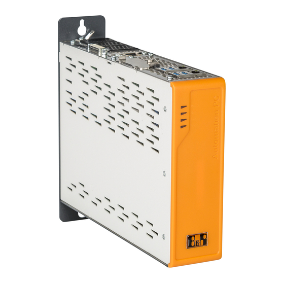
Automation PC 3100
User's manual
Version: 1.00 (September 2018)
Model no.: MAAPC3100-ENG
Translation of the original documentation
All values in this manual are current as of its creation. We reserve the right to change the contents of this manual
without notice. B&R Industrial Automation GmbH is not liable for technical or editorial errors and defects in this
manual. In addition, B&R Industrial Automation GmbH assumes no liability for damages that are directly or indirectly
attributable to the delivery, performance or use of this material. We point out that the software and hardware
designations and brand names of the respective companies used in this document are subject to general trademark,
brand or patent protection.
Advertisement
Table of Contents


Need help?
Do you have a question about the Automation PC 3100 and is the answer not in the manual?
Questions and answers