Table of Contents
Advertisement
Quick Links
Advertisement
Table of Contents
Troubleshooting

Subscribe to Our Youtube Channel
Related Manuals for Eaton Network-M2


Summary of Contents for Eaton Network-M2
- Page 1 UPS Network Management Card Network-M2 User's Guide English 10/15/2020 2.0.5...
- Page 3 Google™ is a trademark of Google Inc. All other trademarks are properties of their respective companies. ©Copyright 2019 Eaton Corporation. All rights reserved. No part of this document may be reproduced in any way without the express written approval of Eaton Corporation.
-
Page 4: Table Of Contents
1 Table of Contents TABLE OF CONTENTS ............................4 INSTALLING THE NETWORK MANAGEMENT MODULE ................10 Unpacking the Network module............................10 Mounting the Network Module ............................10 Wiring the RS-485 Modbus RTU terminal ..........................10 2.3.1 Modbus Common/GND (0V pin on terminal block) connection..................11 2.3.2 Cable shield connection (foiled or braised) ........................ - Page 5 3.4.2 Outlets - Group 1/ Group 2 ............................. 50 3.4.3 Access rights per profiles ............................... 51 3.4.4 Troubleshooting................................51 Protection ..................................... 52 3.5.1 Agents list..................................52 3.5.2 Agent shutdown sequencing............................57 3.5.3 Scheduled shutdown..............................60 3.5.4 Shutdown on power outage ............................61 Environment ..................................
- Page 6 4.1.1 Commissioning................................159 4.1.2 Testing LDAP authentication ............................160 4.1.3 Limitations ..................................160 Pairing agent to the Network Module ..........................160 4.2.1 Pairing with credentials on the agent ........................... 160 4.2.2 Pairing with automatic acceptance (recommended if done in a secure and trusted network)........161 4.2.3 Pairing with manual acceptance ...
- Page 7 5.2.3 References ................................... 200 Configuring user permissions through profiles........................201 Decommissioning the Network Management module ...................... 201 SERVICING THE EMP ............................. 202 Description and features ..............................202 Unpacking the EMP................................202 Installing the EMP ................................203 6.3.1 Defining EMPs address and termination ........................203 6.3.2 Mounting the EMP ...............................
- Page 8 7.7.2 Contextual help................................242 7.7.3 get release info................................243 7.7.4 history................................... 244 7.7.5 ldap-test..................................244 7.7.6 logout.................................... 246 7.7.7 maintenance ................................. 246 7.7.8 modbus_message_display ............................246 7.7.9 modbus_statistics................................. 247 7.7.10 netconf ..................................248 7.7.11 ping and ping6 ................................250 7.7.12 reboot ...................................
- Page 9 8.8.3 Action ................................... 265 SNMPv3 password management issue with Save and Restore ..................265 8.9.1 Affected FW versions..............................265 8.9.2 Symptom ..................................266 8.9.3 Cause.................................... 266 8.9.4 Action ................................... 266 8.10 The alarm list has been cleared after an upgrade....................... 266 8.10.1 Symptom ..................................
-
Page 10: Installing The Network Management Module
Unpacking the Network module 2 Installing the Network Management Module 2.1 Unpacking the Network module The Network-M2 will include the following accessories: • QuickStart • USB AM to Micro USB/M/5P 5ft Cable Packing materials must be disposed of in compliance with all local regulations concerning waste. -
Page 11: Modbus Common/Gnd (0V Pin On Terminal Block) Connection
Wiring the RS-485 Modbus RTU terminal If the Modbus Network Module is the last device installed in the network chain or the length of the network cable is excessive, termination needs to be enabled. For details on termination, see the Installing the Network Management Module>>>Wiring the RS-485 Modbus RTU terminal>>>Configuring the termination section. -
Page 12: Configuring The Termination
Wiring the RS-485 Modbus RTU terminal Belden 9843-24AWG or equivalent cabling (3 twisted-pair shielded 120Ω cable with ground) is recommended. 2.3.5 Configuring the termination If the INDGW card is the last device installed in the network chain or the length of the network cable is excessive, termination needs to be enabled. - Page 13 Wiring the RS-485 Modbus RTU terminal Peel off the protection: Change the position of the termination switch according to your needs: Switch position No termination (default) Termination for two-wire networks One of the two position below can be used: Installing the Network Management Module – ...
-
Page 14: Accessing The Network Module
Accessing the Network Module Termination for four-wire networks 2.4 Accessing the Network Module 2.4.1 Accessing the web interface through Network 2.4.1.1 Connecting the network cable Security settings in the Network Module may be in their default states. For maximum security, configure through a USB connection before connecting the network cable. Connect a standard ... -
Page 15: Accessing The Web Interface Through Rndis
Accessing the Network Module If your device has an LCD, from the LCD’s menu, navigate to Identification>>>"COM card IPv4". • Note the IP address of the card. • Go to the section: Accessing the web interface through Network. 2.4.2.1.2 With web browser through the configuration port For example, if your device does not have an LCD, the IP address can be discovered by accessing the web interface through RNDIS and browsing to Settings>Network. - Page 16 Accessing the Network Module 2.4.3.2 Web interface access through RNDIS 2.4.3.2.1 Configuring the RNDIS a Automatic configuration RNDIS driver is used to emulate a network connection from USB. After the card is connected to the PC, Windows® OS will automatically search for the RNDIS driver. On some computers, the OS can find the RNDIS driver then configuration is completed, and you can go to Accessing the web interface.
- Page 17 Accessing the Network Module STEP 4 – Then enter the configuration as below and validate (IP = 169.254.0.150 and mask = 255.255.0.0), click OK, then click on Close. Installing the Network Management Module – 17...
-
Page 18: Accessing The Card Through Serial Terminal Emulation
2.4.3.2.2 Accessing the web interface STEP 1 – Be sure that the Device is powered on. STEP 2 – On the host computer, download the rndis.7z file from the website www.eaton.com/downloads and extract it. For more information, navigate to Servicing the Network Management Module>>>Accessing to the latest Network Module firmware/ driver section. - Page 19 After the card is connected to the PC, manual configuration of the driver is needed for Windows® OS to discover the serial connection. STEP 1 – On the host computer, download the rndis.7z file from the website www.eaton.com/downloads and extract it. STEP 2 – Plug the USB cable and go to Windows® Device Manager.
-
Page 20: Modifying The Proxy Exception List
Accessing the Network Module STEP 7 – The installation is successful when the COM port number is displayed for the Gadget Serial device in the Windows® Device Manager. 2.4.4.3 Accessing the card through Serial It is intended mainly for automated configuration of the network and time settings of the network card. It can also be used for troubleshooting and remote reboot/reset of the network interface in case the web user interface is not accessible. - Page 21 Accessing the Network Module • Select the Connections tab • Press LAN Settings • Press ADVANCED • Add the address 169.254. * Installing the Network Management Module – 21...
-
Page 22: Configuring Modbus
Configuring Modbus • Press OK. • Close Internet Explorer and re-open it. • Now you can access the address 169.254.0.1 with Internet Explorer and any other browser. 2.5 Configuring Modbus 2.5.1 Configuring the communication parameters • Access the web interface through Network or RNDIS •... -
Page 23: Modbus Communication Monitoring Tool
Configuring Modbus • Type: Register/Discrete • Size in bytes • Number of modbus registers • Writable: True/False • Representation: Int16/Uint16/String/Boolean/... • Name • Description • Unit (Kelvin, A, V, W, VA, %, Hz, min, ...) • Status to 0: status when the discrete equal 0 •... - Page 24 Configuring Modbus Installing the Network Management Module – 24...
- Page 25 Configuring Modbus Installing the Network Management Module – 25...
- Page 26 Configuring Modbus Installing the Network Management Module – 26...
-
Page 27: Configuring The Network Module Settings
Configuring the Network Module settings 2.6 Configuring the Network Module settings Use the web interface to configure the Network Module. The main web interface menus are described below: 2.6.1 Menu structure Home: Overview and status of the Device (Active alarms, Outlet status, ...). Installing the Network Management Module – 27... - Page 28 Configuring the Network Module settings Meters: Power quality meters and logs. Controls: Device and outlets control. Protection: Agents list, Agents shutdown sequencing, Shutdown on power outage. Environment: Commissioning/Status, Alarm configuration, Information. Settings: Network Module settings. Maintenance: Firmware, Services, Resources, System logs. Legal: Legal information, Availability of source code, Notice for proprietary elements. Profile: Displays user profile, password change, account information and logout.
-
Page 29: Contextual Help Of The Web Interface
Login page 3 Contextual help of the web interface 3.1 Login page The page language is set to English by default but can be switched to browser language when it is managed. After navigating to the assigned IP address, accept the untrusted certificate on the browser. 3.1.1 Logging in for the first time 3.1.1.1 1. Enter default password As you are logging into the Network Module for the first time you must enter the factory set default username and password. -
Page 30: Troubleshooting
Home 3.1.2 Troubleshooting How do I log in if I forgot my password? Action • Ask your administrator for password initialization. • If you are the main administrator, your password can be reset manually by following steps described in the Servicing the Network Management Module>>>Recovering main administrator password Web user interface is not up to date after a FW upgrade Symptom After an upgrade:... -
Page 31: Information/Status On The Top Bar
Home 3.2.1 Information/Status on the top bar • Card name: Displays the card name. • Device name: Displays by default the device model or the system name if filled in the section Contextual help>>>Maintenance>>>System information. • Date and time: Displays local time but not the UTC time. •... - Page 32 Home Controls: Device and outlets control. Protection: Agents list, Agents shutdown sequencing, Shutdown on power outage. Environment: Commissioning/Status, Alarm configuration, Information. Settings: Network Module settings. Maintenance: Firmware, Services, Resources, System logs. Legal: Legal information, Availability of source code, Notice for proprietary elements. Profile: Displays user profile, password change, account information and logout. Help: Opens full documentation in a separate browser page.
-
Page 33: Energy Flow Diagram
Home 3.2.3 Energy flow diagram 3.2.3.1 Line interactive UPS 3.2.3.2 Online UPS 3.2.3.3 ATS Contextual help of the web interface – 33... - Page 34 Home 3.2.3.4 Diagram elements description Description and Description Possible states below the symbol symbols Good Warning Fault Input Main utility input. In range Out of nominal range Output Output of the UPS. Protected In overload In short circuit Powered Not protected AVR device The equipment is protected and...
- Page 35 Home Maintenance bypass Maintenance bypass closed. Maintenance (optional) ATS device The equipment is powered through an ATS device. Description and Description Possible states symbols Green Orange Black Wiring Electrical connection between Energy flow In overload No energy blocks. Out of nominal range Unknown 3.2.3.5 Details ...
-
Page 36: Outlet Status
Home Input measures Output measures Voltage (V) Voltage (V) Current (A) Current (A) Frequency (Hz) Frequency (Hz) 3.2.3.6.2 Example #2 Dual input sources with 3 phases in and 3 phases out Input measures (main and secondary) Output measures Phase #1 Phase #2 Phase #3 Phase #1... -
Page 37: Energy Flow Diagram Examples
Home 3.2.7 Energy flow diagram examples 3.2.7.1 Line interactive UPS 3.2.7.1.1 Normal mode 3.2.7.1.2 Buck/Boost mode Contextual help of the web interface – 37... - Page 38 Home 3.2.7.1.3 Battery mode 3.2.7.1.4 Off mode Contextual help of the web interface – 38...
- Page 39 Home 3.2.7.2 Online UPS with single input source 3.2.7.2.1 Online mode 3.2.7.2.2 Bypass mode Contextual help of the web interface – 39...
- Page 40 Home 3.2.7.2.3 Battery mode 3.2.7.2.4 Off mode Contextual help of the web interface – 40...
- Page 41 Home 3.2.7.2.5 HE mode / ESS mode 3.2.7.3 Online UPS with dual inputs sources and Maintenance bypass 3.2.7.3.1 Online mode Contextual help of the web interface – 41...
- Page 42 Home 3.2.7.3.2 Bypass mode 3.2.7.3.3 Battery mode Contextual help of the web interface – 42...
- Page 43 Home 3.2.7.3.4 HE mode / ESS mode 3.2.7.3.5 Maintenance bypass mode Contextual help of the web interface – 43...
-
Page 44: Access Rights Per Profiles
Home 3.2.7.4 ATS 3.2.7.4.1 Normal mode 3.2.7.4.2 Prefered source missing 3.2.8 Access rights per profiles Administrator Operator Viewer Home 3.2.8.1 For other access rights For other access rights, see the Information>>>Access rights per profiles section. Contextual help of the web interface – 44... -
Page 45: Meters
Meters 3.3 Meters Gauge color code: • Green: Value inside thresholds. • Orange/Red: Value outside thresholds. • Grey: No thresholds provided by the device. 3.3.1 Main utility input Displays the product main utility measures. • Current (A) • Voltage (V) 3.3.2 Second utility input (if available) Contextual help of the web interface – ... -
Page 46: Output
Meters If presents, displays the product second utility measures. • Current (A) • Voltage (V) 3.3.3 Output • Voltage (V) • Power (W) • Current (A) 3.3.4 Battery status Battery status section is an overview of the battery information. The information displayed depends on the device. Contextual help of the web interface – ... -
Page 47: Battery Health
Meters 3.3.4.1 Overview/Environment • Type • Nominal capacity • Nominal voltage • Capacity remaining • Runtime • State • Recommended replacement date • State of health • Voltage • Current • Temperature • Min cell voltage • Max cell voltage •... -
Page 48: Logs
Meters • None • Scheduled • In progress • Aborted • Done 3.3.6 Logs This log configuration allows to define the log acquisition frequency of the Device measures only. The sensors measures logs acquisition is not settable and done every minutes. Sensors measures logs are accessible in Environment menu. -
Page 49: Access Rights Per Profiles
Controls 3.3.7.1 For other settings For other settings, see the Information>>>Default settings parameters section. 3.3.8 Access rights per profiles Administrator Operator Viewer Meters Battery health: Launch test/Abort Logs configuration 3.3.8.1 For other access rights For other access rights, see the Information>>>Access rights per profiles ... -
Page 50: Outlets - Group 1/ Group 2
Controls • Safe OFF This will shut off the load. Protected applications will be safely powered down. This control is available only if the status is not OFF and if there are no active commands running. • Safe reboot This will shut off and then switch ON the load. -
Page 51: Access Rights Per Profiles
Controls This control is available only if the status is not OFF and if there are no active commands running. • Switch ON This will switch ON the load connected to the associated load segment. This control is available when status is OFF and if there are no active commands running. 3.4.2.3 Pending action Displays the delay before shutdown and delay before startup. -
Page 52: Protection
After automatic acceptance, make sure that all listed agents belong to your infrastructure. If not, access may be revoked using the Delete button. For maximum security, Eaton recommend following one of the two methods on the certificate settings page: • Import client certificates manually. - Page 53 Protection 3.5.1.2 Agents list table The table displays the IPP agent list that is connected to the Network Module and includes the following details: • Name • Address • Version of the Agent • Power source (Policy) • Delay (in seconds) • OS shutdown duration (in seconds) •...
- Page 54 Protection 3.5.1.5 Troubleshooting Card wrong timestamp leads to "Full acquisition has failed" error message on Software Symptoms: IPP/IPM shows the error message "The full data acquisition has failed" even if the credentials are correct. Possible cause: The Network module timestamp is not correct. Probably the MQTT certificate is not valid at Network module date.
- Page 55 Protection Software is not able to communicate with the Network module Symptoms • In the Network Module, in Contextual help>>>Protection>>>Agent list>>>Agent list table , agent is showing "Lost" as a status. • In the Network Module, in Contextual help>>>Settings>>>Certificate>>>Trusted remote certificates , the status of the Protected applications (MQTT) is showing "Not valid yet".
- Page 56 *.0 that (are) located folder Eaton\IntelligentPowerProtector\configs\tls. Client server is not restarting Symptom Utility power has been restored, the UPS and its load segments are powered on, but the Client server does not restart. Possible Cause The “Automatic Power ON” server setup setting might be disabled.
-
Page 57: Agent Shutdown Sequencing
Protection 3.5.2 Agent shutdown sequencing 3.5.2.1 Agent shutdown sequence timing All agents that are connected to the Network Module are displayed in tables by power sources. • Primary • Group 1 • Group 2 The 'local agent' setting is used for setting for example a minimum shutdown duration, or a power down delay for a load segment that has no registered shutdown agents. - Page 58 Protection • Name • Delay (in seconds) • OS shutdown duration (in seconds) 3.5.2.2 Actions 3.5.2.2.1 Set Delay Select and directly change the setting in the table and then Save. 3.5.2.2.2 Set OS shutdown duration Select and directly change the setting in the table and then Save. 3.5.2.3 Examples Examples below show the impact of agent settings on the shutdown sequence for a shutdown or an immediate shutdown.
- Page 59 Protection 3.5.2.3.2 Example #2 → Shutdown time: 180s → Immediate shutdown time: 180s Contextual help of the web interface – 59...
-
Page 60: Scheduled Shutdown
Protection The trigger in the diagram is the moment when the shutdown sequence starts, and it is defined in the Contextual help>>>Protection>>>Scheduled shutdown or the Contextual help>>>Protection>>>Shutdown on power outage sections for each power source. 3.5.2.4 Access rights per profiles Administrator Operator Viewer Protection/Agent settings 3.5.2.4.1 For other access rights For other access rights, see the Information>>>Access rights per... -
Page 61: Shutdown On Power Outage
Protection 3.5.3.2.2 Delete Select a schedule shutdown and press the Delete button to delete the scheduled shutdown. 3.5.3.2.3 Edit Press the pen icon to edit schedule shutdown and to access the settings: 3.5.3.3 Access rights per profiles Administrator Operator Viewer Protection/Scheduled shutdowns 3.5.3.3.1 For other access rights For other access rights, see the... - Page 62 Protection in the correct order. For example, applications first, database servers next, and storage last. It is also possible to turn off some outlets to reduce power consumption and get longer battery runtime for the most important devices. For examples on Powering down applications see the Servicing the Network Management Module>>>Powering down/up applications examples section.
- Page 63 Protection • To initiate the sequence when the battery reaches the set capacity in (%) • To initiate or end the shutdown sequence after the set time in (s) before the end of backup time. When there are several conditions to start the shutdown sequence, the shutdown sequence will start as soon as one of the condition is reached.
- Page 64 Protection Example 2: Immediate OFF Example 4: Custom Contextual help of the web interface – 64...
- Page 65 Protection Settings #1 Contextual help of the web interface – 65...
- Page 66 Protection Settings #2 3.5.4.1.2 On low battery warning In some cases, like a renewed power failure or failed battery, the capacity is much lower than anticipated. The UPS gives a Low battery warning when there is 2 - 3 minutes of estimated runtime left, depending on the UPS and its settings. This time is typically enough for shutting down a server but does not allow sophisticated sequential shutdown schemes.
- Page 67 Protection 3.5.4.1.3 When utility comes back These settings define the restart sequence when utility comes back. For example, this allows sequential startup of the IT system so that network and storage devices are connected to 'Primary' and start up immediately. After a delay database servers in Group1 are powered up, and then application and web servers in Group 2 are powered up.
-
Page 68: Environment
Environment 3.5.4.3 Troubleshooting Action not allowed in Control/Schedule/Power outage policy Symptom Below message is displayed when you access the Control, Schedule or Power outage policy page. This action is not allowed by the UPS. To enable it, please refer to the user manual of the UPS and its instructions on how to configure the UPS settings and allow remote commands. - Page 69 Environment • Name • Location – location-position-elevation • Temperature • Humidity • Dry contact #1 – Status and name • Dry contact #2 – Status and name • Communication – Connected/Lost with dates 3.6.1.2 Actions 3.6.1.2.1 Download sensors measures Press the Download sensors measures button to download the sensors log file: If available, possible measures are listed below: •...
- Page 70 Environment 1. Select the sensors. 2. Press the Define offset button to adjust the temperature and humidity offsets of the selected sensors. 3. Extend the temperature or humidity section. 4. Set the offsets in the cell, temperatures and humidity will be updated accordingly. 5.
- Page 71 Environment The dry contact is close and this is normal because it is configured as normally close. The dry contact is open and this is normal because it is configured as normally open. The dry contact is open and this is not normal because it is configured as normally close. The dry contact is close and this is not normal because it is configured as normally open.
- Page 72 Environment 3.6.1.5 Troubleshooting EMP detection fails at discovery stage In the Network Module, in Contextual help>>>Environment>>>Commissioning/Status , EMPs are missing in the Sensor commissioning table. Symptom #1 The EMPs green RJ45 LED (FROM DEVICE) is not ON. Possible causes The EMPs are not powered by the Network module. Action #1-1 Launch again the discovery, if it is still not ok, go to Action #1-2.
-
Page 73: Alarm Configuration
Environment 2- Launch the discovery. 3.6.1.5.1 For other issues For details on other issues, see the Troubleshooting section. 3.6.2 Alarm configuration Humidity, temperatures or dry contacts deactivated during commissioning are not displayed. Gauge color code: • Green: Value inside thresholds. • Orange/Red: Value outside thresholds. - Page 74 Environment c Set Hysteresis Enable the alarm first and change the setting in the table and then Save. The hysteresis is the difference between the value where the alarm turns ON from turning OFF and the value where it turns OFF from turning ON.
- Page 75 Environment 3.6.2.3 Dry contacts The table shows the following settings for each dry contact: • Name • Location • Enabled – yes/no • Alarm severity – Info/Warning/Critical 3.6.2.3.1 Actions a Set Enabled Enable the alarm first and then change the setting in the table and then Save. When disabled, no alarm will be sent.
-
Page 76: Information
Environment Temperature Enabled — No Enabled — No/Yes Low critical – 0°C/32°F low critical<low warning<high warning<high critical Low warning – 10°C/50°F High warning – 70°C/158°F High critical – 80°C/176°F Humidity Enabled — No Enabled — No/Yes Low critical – 10% 0%<low critical<low warning<high warning<high critical<100% Low warning – 20% High warning –... - Page 77 Environment • Physical name • Vendor • Part number • Firmware version • UUID • Serial number • Location 3.6.3.1 Access rights per profiles Administrator Operator Viewer Environment/Information 3.6.3.1.1 For other access rights For other access rights, see the Information>>>Access rights per profiles ...
-
Page 78: Settings
Settings 3.7 Settings 3.7.1 General 3.7.1.1 System details 3.7.1.1.1 Location Text field that is used to provide the card location information. Card system information is updated to show the defined location. 3.7.1.1.2 Contact Text field that is used to provide the contact name information. Card system information is updated to show the contact name. - Page 79 Settings 2. Select the time zone for your geographic area from the time zone pull-down menu or with the map. 3. Save the changes. DST is managed based on the time zone. 3.7.1.2 Email notification settings For examples on email sending configuration see the Servicing the Network Management Module>>>Subscribing to a set of alarms for email notification section.
- Page 80 Settings c Edit Press the pen icon to edit email sending configuration: You will get access to the following settings: • Custom name • Email address • Status – Active/Inactive • Hide the IP address from the email body – Disabled/Enabled This setting will be forced to Enabled if Enabled in the SMTP settings. •...
- Page 81 Settings 3.7.1.3 SMTP settings SMTP is an internet standard for electronic email transmission. The following SMTP settings are configurable: Contextual help of the web interface – 81...
- Page 82 Settings • Server IP/Hostname – Enter the host name or IP address of the SMTP server used to transfer email messages in the SMTP Server field. • Port • Default sender address • Hide the IP address from the email body – Disabled/Enabled If Enabled, it will force this setting to Enabled in the Email notification settings.
- Page 83 Settings Email notification settings No email 5 configurations maximum Custom name — 128 characters maximum Email address — 128 characters maximum Hide IP address from the email body — enable/disabled Status — Active/Inactive • Alarm notifications Active — No/Yes All card events – Subscribe/Attach logs Critical alarm –...
- Page 84 Settings 3.7.1.5 Access rights per profiles Administrator Operator Viewer General 3.7.1.5.1 For other access rights For other access rights, see the Information>>>Access rights per profiles section. 3.7.1.6 CLI commands email-test Description mail-test sends test email to troubleshoot SMTP issues. Help Usage: email-test <command>...
- Page 85 Settings time Description Command used to display or change time and date. Help For Viewer and Operator profiles: time -h Usage: time [OPTION]... Display time and date. -h, --help display help page -p, --print display date and time in YYYYMMDDhhmmss format For Administrator profile: time -h Usage: time [OPTION]...
-
Page 86: Local Users
Settings 3.7.2 Local users 3.7.2.1 Local users table The table shows all the supported local user accounts and includes the following details: • Username • Email • Profile • Status – Status could take following values – Inactive/Locked/Password expired/Active For the list of access rights per profile refer to the section Full documentation>>>Information>>>Access rights per profiles. - Page 87 Settings d Global settings Press Save after modifications. Password settings To set the password strength rules, apply the following restrictions: • Minimum length • Minimum upper case • Minimum lower case • Minimum digit • Special character Password expiration To set the password expiration rules, apply the following restrictions: •...
- Page 88 Settings • Main administrator password never expire Main administrator password never expires If this feature is disabled, the administrator account can be locked after the password expiration. If Enabled, the administrator password never expires, make sure it is changed regularly. Lock account •...
- Page 89 Settings Local users 1 user only: 10 users maximum: • Active — Yes • Active — Yes/No • Profile — Administrator • Profile — Administrator/Operator/Viewer • Username — admin • Username — 255 characters maximum • Full Name — blank • Full Name — 128 characters maximum • Email — blank • Email — 128 characters maximum • Phone — blank • Phone — 64 characters maximum •...
-
Page 90: Remote Users
Settings 3.7.2.4.1 For other CLI commands See the CLI commands in the Information>>>CLI section. 3.7.2.5 Troubleshooting How do I log in if I forgot my password? Action • Ask your administrator for password initialization. • If you are the main administrator, your password can be reset manually by following steps described in the Servicing the Network Management Module>>>Recovering main administrator password 3.7.2.5.1 For other issues... - Page 91 Settings 3.7.3.1.1 Actions a Configure 1. Press Configure to access the following LDAP settings: • Active • Base access Contextual help of the web interface – 91...
- Page 92 Settings • Security SSL – None/Start TLS/SSL Verify server certificate • Primary server – Name/Hostname/Port • Secondary server – Name/Hostname/Port • Credentials – Anonymous search bind/Search user DN/Password • Search base – Search base DN • Request parameters • User base DN • User name attribute •...
- Page 93 Settings 1. Press Users preferences to define preferences that will apply to all LDAP users • Language • Temperature • Date format • Time format 2. Click Save. 3.7.3.2 RADIUS Radius is not a secured protocol, for a maximum security, it is recomended to use LDAP over TLS. The table shows all the supported severs and includes the following details: Contextual help of the web interface – ...
- Page 94 Settings • Name - descriptive name for the RADIUS server • Address - hostname or IP address for the RADIUS server • Status - whether the RADIUS server is active or inactive 3.7.3.2.1 Actions a Configure 1. Press Configure to access the following RADIUS settings: •...
- Page 95 Settings b Profile mapping For the list of access rights per profile refer to the section Full documentation>>>Information>>>Access rights per profiles. 1. Press Profile mapping to map RADIUS profile to local profiles. 2. Click Save. c Users preferences All users preferences will apply to all remote users (LDAP, RADIUS). 1.
- Page 96 Settings • Temperature • Date format • Time format 2. Click Save. 3.7.3.3 Default settings and possible parameters - Remote users Default setting Possible parameters LDAP Configure Configure • Active – No • Active – No/yes • Security • Security SSL –...
- Page 97 Settings RADIUS Configure Configure • Active – No • Active – Yes/No • Retry number – 0 • Retry number – 0 to 128 • Primary server • Primary server Name – blank Name – 128 characters maximum Secret – blank Address –...
- Page 98 Settings 3.7.3.5 CLI commands ldap-test Description Ldap-test help to troubleshoot LDAP configuration issues or working issues. Help Usage: ldap-test <command> [OPTION]... Test LDAP configuration. Commands: ldap-test -h, --help, Display help page ldap-test --checkusername <username> [--primary|--secondary] [-v] Check if the user can be retrieve from the LDAP server <username>...
- Page 99 Settings logout Description Logout the current user. Help logout <cr> logout the user whoami Description whoami displays current user information: • Username • Profile • Realm 3.7.3.5.1 For other CLI commands See the CLI commands in the Information>>>CLI section. 3.7.3.6 Troubleshooting How do I log in if I forgot my password? Action •...
-
Page 100: Network & Protocol
Settings 3.7.4 Network & Protocol 3.7.4.1 Network 3.7.4.1.1 IPv4 Any modifications are applied after the Network Module reboots. Press the Edit button to configure the network settings, select either the Manual or DHCP settings option: Contextual help of the web interface – 100... - Page 101 Settings a Manual Select Manual, and then enter the network settings if the network is not configured with a BootP or DHCP server. • Enter the IP Address. The Network Module must have a unique IP address for use on a TCP/IP network. •...
- Page 102 Settings a Current configuration • Address • Gateway b Address settings • Enabled • Mode (Manual/DHCP) • Address • Prefix • Gateway Contextual help of the web interface – 102...
- Page 103 Settings 3.7.4.1.3 DNS/DHCP The DNS is a hierarchical decentralized naming system for computers, services, or other resources connected to the Internet or a private network. Press the Edit button to configure the network settings, select either the Static or Dynamic settings. a Manual •...
- Page 104 Settings • Secondary DNS server. Enter the IP address of the secondary DNS server that provides the translation of the domain name to the IP address when the primary DNS server is not available. b DHCP • Enter the Network Module Hostname. 3.7.4.1.4 Ethernet A LAN is a computer network that interconnects computers within a limited area. ...
- Page 105 Settings 3.7.4.2.1 HTTPS Only https is available. The default network port for https is 443. For additional security, the ports can be changed on this page. Press Save after modifications. Since only https is available, port 80 is not supported. 3.7.4.2.2 Syslog a Settings This screen allows an administrator to configure up to two syslog servers.
- Page 106 Settings Press Save after modifications. 2- Configure the syslog server: • Click the edit icon to access settings. • Enter or change the server name. • Select Yes in the Active drop-down list to activate the server. • Enter the Hostname and Port. • Select the Protocol – UDP/TCP. •...
- Page 107 Settings HTTPS Port — 443 Port — x-xxx Syslog Inactive Inactive/Active • Server#1 • Server#1 Name – Primary Name – 128 characters maximum Status – Disabled Status – Disabled/Enabled Hostname – empty Hostname – 128 characters maximum Port – 514 Port –...
- Page 108 Settings 3.7.4.5 CLI commands netconf Description Tools to display or change the network configuration of the card. Help For Viewer and Operator profiles: netconf -h Usage: netconf [OPTION]... Display network information and change configuration. -h, --help display help page -l, --lan display Link status and MAC address -4, --ipv4...
- Page 109 Settings netconf -h Usage: netconf [OPTION]... Display network information and change configuration. -h, --help display help page -l, --lan display Link status and MAC address -d, --domain display Domain mode, FQDN, Primary and Secondary DNS -4, --ipv4 display IPv4 Mode, Address, Netmask and Gateway -6, --ipv6 display IPv6 Mode, Addresses and Gateway Set commands are used to modify the settings. -s, --set-lan <link speed> Link speed values: auto Auto negotiation 10hf 10 Mbps - Half duplex 10ff 10 Mbps - Full duplex 100hf 100 Mbps - Half duplex 100ff 100 Mbps - Full duplex 1000ff 1.0 Gbps - Full duplex -f, --set-domain hostname <hostname> set custom hostname -f, --set-domain <mode> Mode values: - set custom Network address, Netmask and Gateway: manual <domain name> <primary DNS> <secondary DNS> - automatically set Domain name, Primary and Secondary DNS dhcp -i, --set-ipv4 <mode> Mode values: - set custom Network address, Netmask and Gateway manual <network> <mask> <gateway> - automatically set Network address, Netmask and Gateway dhcp -x, --set-ipv6 <status> Status values: - enable IPv6 enable - disable IPv6 disable...
- Page 110 Settings -> Display Link status and MAC address netconf -l -> Set Auto negotiation to Link netconf -s auto -> Set custom hostname netconf -f hostname ups-00-00-00-00-00-00 -> Set Adress, Netmask and Gateway netconf -i manual 192.168.0.1 255.255.255.0 192.168.0.2 ->...
-
Page 111: Snmp
Settings traceroute and traceroute6 Description Traceroute and traceroute6 utilities are for checking the configuration of the network. Help traceroute Specify maximum number of hops <Hostname or IP> Remote system to trace traceroute6 Specify maximum number of hops <IPv6 address> IPv6 address 3.7.4.5.1 For other CLI commands See the CLI commands in the Information>>>CLI ... - Page 112 Settings SNMP monitoring Battery status, power status, events, and traps are monitored using third-party SNMP managers. To query SNMP data, you do not need to add SNMP Managers to the Notified Application page. To set-up SNMP managers: • Configure the IP address. •...
- Page 113 Settings b Configure the SNMP V1 settings: 1. Click the edit icon on either Read Only or Read/Write account to access settings: 2. Enter the SNMP Community Read-Only string. The Network Module and the clients must share the same community name to communicate.
- Page 114 Settings c Configure the SNMP V3 settings: 1. Click the edit icon on either Read Only or Read/Write account to access settings: 2. Edit the user name. 3. Select Active in the Enabled drop-down list to activate the account. 4. Select access level. •...
- Page 115 Settings 6. If Auth is selected on the communication security mechanism, select the Authentication algorithms. It is recommended to set SHA256/SHA384/SHA512 with the AES192/AES256 Privacy algorithms. • SHA— SHA1 is not recommended as it is not secured. • SHA256—fill in password and privacy keys. The password can be between 8 and 24 characters and use a combination of alphanumeric and the following special characters <>&@#%_=:;,./?|$*.
- Page 116 Settings 3.7.5.2.1 Actions a Add 1. Press the New button to create new trap receivers. 2. Set following settings: • Enabled – Yes/No • Application name • Hostname or IP address • Port • Protocol – V1/V3 • Trap community (V1) / User (V3) 3.
- Page 117 Settings 3.7.5.3 Link to SNMP traps • UPS Mib • ATS Mib • Sensor Mib 3.7.5.4 Default settings and possible parameters - SNMP Default setting Possible parameters SNMP Activate SNMP — disabled Activate SNMP — disable/enable Port — 161 Port — x-xxx SNMP V1 —...
-
Page 118: Modbus
Settings 3.7.5.4.1 For other settings For other settings, see the Information>>>Default settings parameters section. 3.7.5.5 Access rights per profiles Administrator Operator Viewer SNMP 3.7.5.5.1 For other access rights For other access rights, see the Information>>>Access rights per profiles section. 3.7.5.6 Troubleshooting SNMPv3 password management issue with Save and Restore Affected FW versions... - Page 119 Settings This section is only for the Modbus Network ModuleINDGW For instructions on connecting Modbus RTU see the section Installing the Network Management Module>>>Wiring the RS-485 Modbus RTU terminal>>>Configuring the termination. For instructions on configuring Modbus see the section Installing the Network Management Module>>>Configuring Modbus 3.7.6.1 Modbus RTU The following Modbus RTU settings are configurable: •...
- Page 120 Settings 3.7.6.3 Mapping configuration 3.7.6.3.1 Mapping configuration table The table shows all the mapping configuration and includes the following details: • Name • • Transport • Access • Illegal read behaviour • Coil/register base address shift 3.7.6.3.2 Actions a Add Press the New button to create new mapping configuration.
- Page 121 Port — 502 Port — x-xxx Mapping configuration No mapping Name – 128 characters maximum Map – Eaton ModbusMS compatible Transport – RTU/TCP Device ID – from 1 to 247 Access – None/Read only/Read/Write Illegal read behaviour – Return exception/Return zeros Coil/register base address shift –...
- Page 122 Settings 3.7.6.4.1 For other settings For other settings, see the Information>>>Default settings parameters section. 3.7.6.5 Access rights per profiles Administrator Operator Viewer Modbus* *for INDGW only 3.7.6.5.1 For other access rights For other access rights, see the Information>>>Access rights per profiles ...
- Page 123 Settings modbus_statistics This section is only for the Modbus Network Module INDGW Description modbus_statistics displays Modbus RTU and TCP status and server statistics: • Bus character overrun count • Bus frame error count • Bus parity error count • Buffer overrun count •...
-
Page 124: Certificate
Settings 3.7.6.7 Troubleshooting Modbus communication doesn't work Symptoms • Communication doesn't work Refer to the section Servicing the Network Management Module>>>Configuring Modbus to get configuration and testings information. Possible cause • Incorrect communication parameters. Verify that the communication parameters are set to the desired settings. 3.7.6.7.1 For other issues For details on other issues, see the Troubleshooting ... - Page 125 Settings After automatic acceptance, make sure that all listed clients belong to your infrastructure. If not, access may be revoked using the Delete button. The use of this automatic acceptance should be restricted to a secured and trusted network. For maximum security, we recommend following one of the two methods on the certificate settings page: •...
- Page 126 Settings A confirmation window appears, press Continue to proceed, this operation cannot be recovered. Revoke will replace current certificate by a new self-signed certificate. This may disconnect connected applications: - Web browsers - Shutdown application - Monitoring application The certificate that is taken out of use with the revoke action cannot be recovered. b Export Exports the selected certificate on your OS browser window.
- Page 127 Settings • Actions Generate a new self-signed certificate. Generate CSR. Import certificate (only available when CSR is generated). • Details e Generate a new self-signed certificate To replace a selected certificate with a new self-signed certificate. This may disconnect applications such as a Web browser, shutdown application, or monitoring application. This operation cannot be recovered.
- Page 128 Settings 3.7.7.3.1 CA table The table displays certificate authorities with the following details: • Used for • Issued by • Issued to • Valid from • Expiration • Status — valid, expires soon, or expired 3.7.7.3.2 Actions a Import When importing the CA, you must select the associated service, and then upload process can begin through the OS browser window.
- Page 129 Settings 3.7.7.4 Trusted remote certificates The table shows the following information for each trusted remote certificate. • Used for • Issued by • Issued to • Valid from • Expiration In case a certificate expires, the connection with the client will be lost. If this happens, the user will have to recreate the connection and associated certificates.
- Page 130 State or Province — 38 State or Province — 64 characters maximum City or Locality — Grenoble City or Locality — 64 characters maximum Organization name — Eaton Organization name — 64 characters maximum Organization unit — Power quality Organization unit — 64 characters maximum Contact email address —...
- Page 131 Settings 3.7.7.7 CLI commands certificates Description Allows to manage certificates through the CLI. Help certificates <target> <action> <service_name> <target> : - local <action> : - print: provides a given certificate detailed information. - revoke: revokes a given certificate. - export: returns a given certificate contents. - import: upload a given certificate for the server CSR.
- Page 132 Settings 3.7.7.7.1 For other CLI commands See the CLI commands in the Information>>>CLI section. Contextual help of the web interface – 132...
- Page 133 Settings 3.7.7.8 Troubleshooting Software is not able to communicate with the Network module Symptoms • In the Network Module, in Contextual help>>>Protection>>>Agent list>>>Agent list table , agent is showing "Lost" as a status. • In the Network Module, in Contextual help>>>Settings>>>Certificate>>>Trusted remote certificates , the status of the Protected applications (MQTT) is showing "Not valid yet".
- Page 134 *.0 that (are) located folder Eaton\IntelligentPowerProtector\configs\tls. Card wrong timestamp leads to "Full acquisition has failed" error message on Software Symptoms: IPP/IPM shows the error message "The full data acquisition has failed" even if the credentials are correct. Possible cause: The Network module timestamp is not correct. ...
-
Page 135: Ats
Maintenance 3.7.8 ATS This section is only for the ATS device and contains all its settings. • Prefered source – To set the priority on Source 1 or Source 2 (Source 1 by default). • Sensitivity – To set the sensitivity mode for input mains detection (Normal sensitivity by default, Low sensitivity for compatibility with distorted waveform). -
Page 136: System Information
Maintenance 3.8.1 System information System information is an overview of the main Network Module information. The COPY TO CLIPBOARD button will copy the information to the clipboard. 3.8.1.1 Identification • System name – if filled, it replaces the Device model name in the top bar •... - Page 137 Displays the associated firmware version and associated Sha. c Generated on Displays the release date of the firmware. For better performance, security, and optimized features, Eaton recommends to upgrade the Network Module regularly. d Installation on Displays when the firmware was installed in the Network Module.
- Page 138 Maintenance Do not close the web browser or interrupt the operation. Depending on your network configuration, the Network Module may restart with a different IP address. Refresh the browser after the Network module reboot time to get access to the login page. Press F5 or CTRL+F5 to empty the browser to get all the new features displayed on the Web user interface.
-
Page 139: Services
Maintenance 3.8.2.5 Troubleshooting The Network Module fails to boot after upgrading the firmware Possible Cause The IP address has changed. Note: If the application is corrupt, due to an interruption while flashing the firmware for example, the boot will be done on previous firmware. Action Recover the IP address and connect to the card. - Page 140 Maintenance 1. Click Sanitize. A confirmation message displays, click Sanitize to confirm. Depending on your network configuration, the Network Module may restart with a different IP address. Only main administrator user will remain with default login and password. Refresh the browser after the Network module reboot time to get access to the login page. 3.8.3.1.2 Reboot Reboot means restarting the network module operating system.
- Page 141 Maintenance Depending on your network configuration, the Network Module may restart with a different IP address. Refresh the browser after the Network module reboot time to get access to the login page. Communication Lost and Communication recovered may appear in the Alarm section. 3.8.3.1.3 Settings Allow to save and restore the Network module settings.
- Page 142 Maintenance 3.8.3.1.4 Save Below settings are not saved: Local users other than the main administratorSensor settings (commissioning, alarm configuration) To save the Network module settings: 1. Click on Save 2. Select to include the Network settings if needed. A passphrase need to be entered twice to cypher the sensitive data. 3.
- Page 143 Maintenance 5. Click on Restore to confirm 3.8.3.1.6 Maintenance The maintenance report is for the service representative use to diagnose problems with the network module. It is not intended for the user, which is why the file is protected by a password. To download the maintenance report file: Click Download report.
- Page 144 Maintenance 3.8.3.3 CLI commands maintenance Description Creates a maintenance report file which may be handed to the technical support. Help maintenance <cr> Create maintenance report file. -h, --help Display help page reboot Description Tool to Reboot the card. Help Usage: reboot [OPTION] <cr> Reboot the card --help Display help...
- Page 145 Maintenance save_configuration | restore_configuration Description Save_configuration and restore_configuration are using JSON format to save and restore certain part of the configuration of the card. Help save_configuration -h save_configuration: print the card configuration in JSON format to standard output. restore_configuration -h restore_configuration: restore the card configuration from a JSON-formatted standard input.
-
Page 146: Resources
Maintenance sanitize Description Sanitize command to return card to factory reset configuration. Access • Administrator Help sanitize -h, --help Display help page --withoutconfirmation Do factory reset of the card without confirmation <cr> Do factory reset of the card 3.8.3.3.1 For other CLI commands See the CLI commands in the Information>>>CLI ... - Page 147 Maintenance 3.8.4.2 Memory • Total size in MB • Available size in MB • Application size in MB • Temporary files size in MB 3.8.4.3 Storage • Total size in MB • Available size in MB • Used size in MB 3.8.4.4 Access rights per profiles Administrator Operator...
-
Page 148: System Logs
Maintenance 3.8.4.4.1 For other access rights For other access rights, see the Information>>>Access rights per profiles section. 3.8.4.5 CLI commands systeminfo_statistics Description Displays the following system information usage: usage : % upSince : date since the system started total: MB free: MB used: MB tmpfs: temporary files usage (MB) -
Page 149: Legal Information
Legal information For the list of system logs, see the Information>>>System Logs codes section. 3.8.5.2 Access rights per profiles Administrator Operator Viewer System logs 3.8.5.2.1 For other access rights For other access rights, see the Information>>>Access rights per profiles section. 3.9 Legal information This Network Module includes software components that are either licensed under various open source license, or under a proprietary license. -
Page 150: Notice For Proprietary Elements
Legal information 3.9.3 Notice for proprietary elements Provides notice for our proprietary (i.e. non-Open source) elements. 3.9.4 Access rights per profiles Administrator Operator Viewer Legal information 3.9.4.1 For other access rights For other access rights, see the Information>>>Access rights per profiles ... -
Page 151: Alarms
Alarms 3.10 Alarms 3.10.1 Alarm sorting Alarms can be sorted by selecting: • • Active only 3.10.2 Active alarm counter Alarms with a severity set as Good are not taken into account into the counter of active alarms. 3.10.3 Alarm details All alarms are displayed and sorted by date, with alert level, time, description, and status. -
Page 152: Export
Alarms When the number of alarms is above the number of alarms per page, the buttons First, Previous and Next appears to allow navigation in the Alarm list. 3.10.5 Export Press the Export button to download the file. 3.10.6 Clear Press the Clear button to clear alarms that are older than a specified date and up to a defined severity. 3.10.7 Alarms list with codes To get access to the Alarm log codes or the System log codes for email subscription, see sections below: •... -
Page 153: User Profile
User profile 3.11 User profile 3.11.1 Access to the user profile Press the icon on the top right side of the page to access the user profile window: This page is in read-only mode when connected through LDAP and it displays the preferences applied to all LDAP users as configured in the Contextual help>>>Settings>>>Remote users>>>LDAP section. - Page 154 User profile 3.11.2.1 Change password Click on Change password to change the password. In some cases, it is not possible to change the password if it has already been changed within a day period. Refer to the troubleshooting section. Contextual help of the web interface – 154...
-
Page 155: Default Settings And Possible Parameters - User Profile
User profile 3.11.2.2 Edit account If you have the administrator's rights, you can click on Edit account to edit user profile and update the following information: Account details • Full name • Email • Phone • Organization Preferences • Language • Date format •... -
Page 156: Access Rights Per Profiles
User profile Profile Account details: Account details: • Full name — Administrator • Full name — 128 characters maximum • Email — blank • Email — 128 characters maximum • Phone — blank • Phone — 64 characters maximum •... -
Page 157: Troubleshooting
Documentation whoami Description whoami displays current user information: • Username • Profile • Realm 3.11.5.1 For other CLI commands See the CLI commands in the Information>>>CLI section. 3.11.6 Troubleshooting Password change in My profile is not working Symptoms The password change shows " Invalid credentials " when I try to change my password in My profile menu: Possible cause The password has already been changed once within a day period. -
Page 158: Access Rights Per Profiles
Documentation The focus will be made on the contextual page. You can then navigate into below sections: Contextual help Help for each webpage. Extracts from the sections below when they are related to the web page. Servicing the Network Management Module How to install and use the Network module. -
Page 159: Servicing The Network Management Module
Configuring/Commissioning/Testing LDAP 4 Servicing the Network Management Module 4.1 Configuring/Commissioning/Testing LDAP 4.1.1 Commissioning Refer to the section Contextual help>>>Settings>>>Local users to get help on the configuration. 4.1.1.1 Configuring connection to LDAP database This step configures the LDAP client of the network module to request data from an LDAP base. Activate LDAP. -
Page 160: Testing Ldap Authentication
Pairing agent to the Network Module Configure the rules to mapped LDAP users to profile: Enter LDAP group name. Select the profile to assigned. You can define up to 5 mapping rules. All LDAP users belonging to the configured LDAP group will have permissions granted by the associated profile. If a user belongs to multiple LDAP groups mapped to different profiles, the behavior is undefined. -
Page 161: Pairing With Automatic Acceptance (Recommended If Done In A Secure And Trusted Network)
Note: After that stage, the agent creates a client certificate. The power source could show a communication loss since the current client certificate is not trusted by the Network Module. 4. Copy the agent certificate file client.pem that is located in the folder Eaton\IntelligentPowerProtector\configs\tls.. STEP 2: Action on the Network Module 1. Connect to the Network Module... -
Page 162: Powering Down/Up Applications (Examples)
Powering down/up applications (examples) • Enter the password in the Password field. • Click Login. The Network Module web interface appears. 2. Navigate to Contextual help>>>Settings>>>Certificate page 3. In the Trusted remote certificates section, click Import, select Protected applications (MQTT) and then click on CONTINUE 4. - Page 163 Powering down/up applications (examples) 4.3.1.3 Step 2: Agent settings 4.3.1.3.1 Objective Ensure IT solution is shutdown gracefully. 4.3.1.3.2 Resulting setup 1. Install IPP Software on each server (Application, Database servers, Storage) and register the UPS load segment as power source: • Applications: Group 1 •...
- Page 164 Powering down/up applications (examples) Storage is the last one to power down, its availability is maximized, and its shutdown will end 30s before the end of backup time. 3. Set Group 1 and Group 2 to: Custom. Applications must shutdown first so Group 1 has been set to start shutdown when on battery for 30s. Servers must shutdown second, so Group 2 has been set to start shutdown when on battery for 210s, so 3min after the applications.
-
Page 165: Powering Down Non-Priority Equipment First
Powering down/up applications (examples) 4.3.2 Powering down non-priority equipment first 4.3.2.1 Target Powering down non-priority equipment first (immediately) and keep battery power for critical equipment. Powering down critical equipment 3min before the end of backup time. 4.3.2.2 Step 1: Installation setup 4.3.2.2.1 Objective Use load segmentation provided by the UPS to independently control the power supply of each IT equipment categories (Applications, Database servers, Storage). - Page 166 Powering down/up applications (examples) 4.3.2.2.2 Resulting setup UPS provides outlets (Group 1 and Group 2) and a primary output. When primary shuts OFF, both group 1 and group 2 shut OFF immediately. Connections can be done as described below: •...
- Page 167 Powering down/up applications (examples) Critical equipment is the last one to power down, their availability will be maximized and their shutdown will end 180s before the end of backup time. 3. Set Group 2 to: Immediate off. Servicing the Network Management Module – 167...
-
Page 168: Restart Sequentially The It Equipment On Utility Recovery
Powering down/up applications (examples) Non-priority equipment immediately shuts down when on battery for 10s to keep battery power for critical equipment. 4.3.3 Restart sequentially the IT equipment on utility recovery 4.3.3.1 Target Restart the storage first (right after utility recovery), database servers next (2min after utility recovery) and applications last (3min after utility recovery). -
Page 169: Checking The Current Firmware Version Of The Network Module
Firmware version x.xx.x • The Card menu : Contextual help>>>Maintenance>>>Firmware: Active FW version x.xx.x 4.5 Accessing to the latest Network Module firmware/driver/script Download the latest Eaton Network Module firmware, driver or script from the Eaton website www.eaton.com/downloads Servicing the Network Management Module – 169... -
Page 170: Upgrading The Card Firmware (Web Interface / Shell Script)
Upgrading the card firmware (Web interface / shell script) 4.6 Upgrading the card firmware (Web interface / shell script) For instructions on accessing to the latest firmware and script, refer to: Accessing to the latest firmware and script 4.6.1 Web interface To upgrade the Network module through the Web interface, refer to the section: Firmware upgrade through the Web interface. -
Page 171: Changing The Rtc Battery Cell
Changing the RTC battery cell STARTING UPDATE FROM: [FW_Update.tar] to [X.X.X.X] Transfer by scp (FW_Update.tar) to [X.X.X.X] Warning: Permanently added 'X.X.X.X' (ECDSA) to the list of known hosts. Transfer done. Check running upgrade status ... Check firmware binary signature Uncompress and flash upgrade inProgress(%):11 Uncompress and flash upgrade... - Page 172 Changing the RTC battery cell 5. Replace the battery cell, the positive mark (+) should be visible when inserting it. 6. Replace the Network Module and secure the screw, reconnect the Network cable if it was unplugged during the operation. 7.
-
Page 173: Updating The Time Of The Network Module Precisely And Permanently (Ntp Server)
Updating the time of the Network Module precisely and permanently (ntp server) 4.8 Updating the time of the Network Module precisely and permanently (ntp server) For an accurate and quick update of the RTC for the Network Module, we recommend implementing a NTP server as time source for the Network Module. -
Page 174: Resetting Username And Password
Resetting username and password The language of the login page is English by default or browser language when it is supported. 4.11 Resetting username and password 4.11.1 As an admin for other users 1. Navigate to Contextual help>>>Settings>>>Local users. 2. Press the pen icon to edit user information: 3. -
Page 175: Switching To Static Ip (Manual) / Changing Ip Address Of The Network Module
Switching to static IP (Manual) / Changing IP address of the Network Module Peel off the protection : Change the position of switch number 3, this change is detected during next power ON and the sanitization will be applied : Case 1 : ... -
Page 176: Reading Device Information In A Simple Way
Reading device information in a simple way • Default Gateway Save the changes. 4.14 Reading device information in a simple way 4.14.1 Web page The product information is located in the Contextual help>>>Home>>>Energy flow diagram>>>Details, specifically with the button on the top of the diagram: 4.15 Subscribing to a set of alarms for email notification 4.15.1 Example #1: subscribing only to one alarm (load unprotected) Follow the steps below:... - Page 177 Subscribing to a set of alarms for email notification Logs will be attached by default in that example even if there is no subscription on card or device events. 4. Press Save, the table will show the new configuration. Servicing the Network Management Module – 177...
-
Page 178: Example #2: Subscribing To All Critical Alarms And Some Specific Warnings
Subscribing to a set of alarms for email notification 4.15.2 Example #2: subscribing to all Critical alarms and some specific Warnings Follow the steps below: 1. Navigate to Contextual help>>>Settings>>>General>>>Email notification settings. 2. Press the button New to create a new configuration. 3. -
Page 179: Saving/Restoring/Duplicating Network Module Configuration Settings
Saving/Restoring/Duplicating Network module configuration settings 4.16 Saving/Restoring/Duplicating Network module configuration settings 4.16.1 Modifying the JSON configuration settings file 4.16.1.1 JSON file structure The JSON file is structured into 3 blocks: Servicing the Network Management Module – 179... - Page 180 Saving/Restoring/Duplicating Network module configuration settings 4.16.1.1.1 File block File block cannot be modified, this is the mandatory structure of the JSON file. 4.16.1.1.2 Feature block Feature block contains the full definition of a feature. If it is removed from the JSON file, this feature settings will not be updated/restored in the card. 4.16.1.1.3 Data block Data block contains all the feature settings values.
- Page 181 Saving/Restoring/Duplicating Network module configuration settings When restoring the file, the corresponding setting will be updated based on the cyphered value. without 4.16.1.2.2 The JSON file is saved passphrase All sensitive data will have below structure: When restoring the file, the corresponding setting will not be set. This may lead to restoration failure if corresponding setting was not previously set with a valid value.
- Page 182 Saving/Restoring/Duplicating Network module configuration settings Original file: Modified file: 4.16.1.3.4 Making a partial update/restoration a Example: Updating/Restoring only LDAP settings If you restore below JSON content, only LDAP settings will be updated/restored, everything else will remain unchanged. Servicing the Network Management Module – 182...
- Page 183 Saving/Restoring/Duplicating Network module configuration settings "version": "x.x", "features": { "ldap": { "data": { "version": "x.x", "certificateData": [], "dmeData": { "enabled": true, "baseAccess": { "security": {"ssl": 1,"verifyTlsCert": false}, "primary": {"name": "Primary","hostname": "xxxxxxxxx","port": xxxx}, "secondary": {"name": "xxxxxx","hostname": "xxxxxx","port": xxxx}, "credentials": { "anonymousSearchBind": false, "searchUserDN": "CN=xxxx,OU=xxxx,OU=xxxx,OU=xxxx,DC=xxxx,DC=xxxx", "password": {"plaintext": null}},...
- Page 184 Saving/Restoring/Duplicating Network module configuration settings Account service preferences>>>language de: Deutsch en: English es: Español fr: Français it: Italiano ja: 日本語 ru: русский zh_Hans: 简体中文 zh_Hant:繁體中文 preferences>>>dateFormat Y-m-d: YYYY-MM-DD d-m-Y: DD-MM-YYYY d.m.Y: DD.MM.YYYY d/m/Y: DD/MM/YYYY m/d/Y: MM/DD/YYYY d m Y: DD MM YYYY preferences>>>timeFormat 1: 24h 0: 12h...
- Page 185 Values example Modbus mapping>>>configurations>>>transport 1: RTU 2: TCP mapping>>>configurations>>>map network_card: Card System Information modbus_ms: Eaton ModbusMS compatible mapping>>>configurations>>>transportFilter *: Access to all xx.xxx.xx.xx;yy.yyy.yy.yy;...: Access to a list of IP address mapping>>>configurations>>>deviceID 1 to 247 mapping>>>configurations>>>access 0: None 1: Read only 3: Read/Write mapping>>>configurations>>>illegalReadBehavior...
- Page 186 Values example Modbus mapping>>>configurations>>>transport 1: RTU 2: TCP mapping>>>configurations>>>map network_card: Card System Information modbus_ms: Eaton ModbusMS compatible mapping>>>configurations>>>transportFilter *: Access to all xx.xxx.xx.xx;yy.yyy.yy.yy;...: Access to a list of IP address mapping>>>configurations>>>deviceID 1 to 247 mapping>>>configurations>>>access 0: None 1: Read only 3: Read/Write mapping>>>configurations>>>illegalReadBehavior...
- Page 187 Saving/Restoring/Duplicating Network module configuration settings preferences>>>dateFormat Y-m-d: YYYY-MM-DD d-m-Y: DD-MM-YYYY d.m.Y: DD.MM.YYYY d/m/Y: DD/MM/YYYY m/d/Y: MM/DD/YYYY d m Y: DD MM YYYY preferences>>>timeFormat 1: 24h 0: 12h preferences>>>temperatureUnit 1: °C 2: °F Data Values example Schedule scheduler 1: Primary 2: Group 1 3: Group 2 recurrence 0: once...
-
Page 188: Saving/Restoring/Duplicating Settings Through The Cli
Saving/Restoring/Duplicating Network module configuration settings Web server 4.16.2 Saving/Restoring/Duplicating settings through the CLI Navigate to Information>>>CLI>>>save_configuration | restore_configuration section to get example on how to save and restore settings through the CLI. 4.16.3 Saving/Restoring/Duplicating settings through the Web interface Navigate to Contextual help>>>Maintenance>>>Services section to get information on how to save and restore settings through the Web interface. -
Page 189: Securing The Network Management Module
5.1 Cybersecurity considerations for electrical distribution systems 5.1.1 Purpose The purpose of this section is to provide high-level guidance to help customers across industries and applications apply Eaton solutions for power management of electrical systems in accordance with current cybersecurity standards. -
Page 190: Defense In Depth
Cybersecurity considerations for electrical distribution systems 5.1.4.1 Paths to the control network The paths in above figure include: • External users accessing the network through the Internet • Misconfigured firewalls • Unsecure wireless routers and wired modems • Infected laptops located elsewhere that can access the network behind the firewall •... -
Page 191: Designing For The Threat Vectors
Cybersecurity considerations for electrical distribution systems 5.1.6 Designing for the threat vectors 5.1.6.1 Firewalls Firewalls provide the capability to add stringent and multifaceted rules for communication between various network segments and zones in an ICS network. They can be configured to block data from certain segments, while allowing the relevant and necessary data through. - Page 192 Cybersecurity considerations for electrical distribution systems 5.1.6.2.1 Three-tier architecture for a secure control network Above figure shows that the control networks are divided into layers or zones based on control functions, which are then connected by conduits (connections between the zones) that provide security controls to: •...
-
Page 193: Policies, Procedures, Standards, And Guidelines
Cybersecurity considerations for electrical distribution systems 5.1.6.3 Intrusion detection and prevention systems (IDPS) These are systems that are primarily focused on identifying possible incidents in an ICS network, logging the information about them, attempting to stop them, and reporting them to ICS security administrators. Because these systems are critical in an ICS network, they are regular targets for attacks and securing them is extremely important. - Page 194 Cybersecurity considerations for electrical distribution systems Existing (traditional) IT standards and policies may not apply (or have not been considered) for control systems. A gap analysis should be performed to determine which components are not covered (or not adequately covered) by existing policies. Relationships with existing policies and standards should be explicitly identified and new or supporting policies should be developed.
-
Page 195: Conclusion
Cybersecurity considerations for electrical distribution systems general IT components, while the Industrial Control Systems Cyber Emergency Response Team (ICS-CERT) publishes advisories specific to control systems. A regular patch deployment schedule should be established for each component in the environment. Depending on the component, this could range from a monthly schedule to an as-needed deployment, depending on the historical frequency of patch or vulnerability related issues for the component or the vendor. -
Page 196: References
Cybersecurity considerations for electrical distribution systems SCADA Supervisory Control and Data Acquisition SNMP Simple Network Management Protocol Secure Shell SIEM Security Information and Event Management Universal Serial Bus 5.1.11 References [1] Recommended Practice: Improving Industrial Control Systems Cybersecurity with Defense-In-Depth Strategies, October 2009 https://ics-cert.us-cert.gov/sites/default/files/FactSheets/NCCIC%20ICS_FactSheet_Defense_in_Depth_Strategies_S508C.pdf [2] NIST.SP.800-82 Guide to Industrial Control Systems (ICS) Security, June 2011 http://csrc.nist.gov/publications/nistpubs/800-82/SP800-82-final.pdf... -
Page 197: Cybersecurity Recommended Secure Hardening Guidelines
Eaton is committed to minimizing the Cybersecurity risk in its products and deploys cybersecurity best practices and latest cybersecurity technologies in its products and solutions; making them more secure, reliable and competitive for our customers. ... - Page 198 It is extremely important to securely configure the logical access mechanisms provided in Network module to safeguard the device from unauthorized access. Eaton recommends that the available access control mechanisms be used properly to ensure that access to the system is restricted to legitimate users only. And, such users are restricted to only the privilege levels necessary to complete their job roles/functions.
- Page 199 Eaton recommends segmentation of networks into logical enclaves and restrict the communication to host-to-host paths. This helps protect sensitive information and critical services and limits damage from network perimeter breaches. At a minimum, a utility Industrial Control Systems network should be segmented into a three-tiered architecture (as recommended by NIST SP800-82[R3]) for better security control.
-
Page 200: References
Conduct regular Cybersecurity risk analyses of the organization /system. Eaton has worked with third-party security firms to perform system audits, both as part of a specific customer’s deployment and within Eaton’s own development cycle process. Eaton can provide guidance and support to your organization’s effort to perform regular cybersecurity audits or assessments. -
Page 201: Configuring User Permissions Through Profiles
Configuring user permissions through profiles [R3] NIST SP 800-82 Rev 2, Guide to Industrial Control Systems (ICS) Security, May 2015: https://ics-cert.us-cert.gov/Standards-and-References [R4] National Institute of Technology (NIST) Interagency “Guidelines on Firewalls and Firewall Policy, NIST Special Publication 800-41”, October 2009: http://nvlpubs.nist.gov/nistpubs/Legacy/SP/nistspecialpublication800-41r1.pdf 5.3 Configuring user permissions through profiles The user profile can be defined when creating a new users or changed when modifying an existing one. -
Page 202: Servicing The Emp
Description and features 6 Servicing the EMP 6.1 Description and features The optional Environmental Monitoring Probe EMPDT1H1C2 enables you to collect temperature and humidity readings and monitor the environmental data remotely. You can also collect and retrieve the status of one or two dry contact devices (not included). Up to 3 Environmental Monitoring Probe can be daisy chained on one device. -
Page 203: Installing The Emp
Installing the EMP 6.3 Installing the EMP 6.3.1 Defining EMPs address and termination 6.3.1.1 Manual addressing Address must be defined before the EMP power-up otherwise the changes won't be taken into account. Do not set Modbus address to 0, otherwise the EMP will not be detected. Define different address for all the EMPs in the daisy-chain. - Page 204 Installing the EMP Bottom mounting capabilities: Side mounting: • magnets • magnets • keyholes • tie wraps • tie wraps • nylon fastener 6.3.2.1 Rack mounting with keyhole example To mount the EMP on the rack, use the supplied screw, washer and nut. Then, mount the EMP on the screw and tighten it.
- Page 205 Installing the EMP Bottom mounting Side mounting 6.3.2.3 Wall mounting with screws example To mount the EMP on the wall close to the rack, use the supplied screw and screw anchor. Then, mount the EMP on the screw and tighten it. 6.3.2.4 Wall mounting with nylon fastener example To mount the EMP within the enclosure environment, attach one nylon fastener to the EMP and the other nylon fastener to an enclosure rail post.
-
Page 206: Cabling The First Emp To The Device
Installing the EMP 6.3.3 Cabling the first EMP to the device 6.3.3.1 Available Devices 6.3.3.1.1 Network-M2/INDGW Network-M2 INDGW 6.3.3.2 Connecting the EMP to the device Address must be defined before the EMP power-up otherwise the changes won't be taken into account. -
Page 207: Daisy Chaining Emps
Installing the EMP STEP 2 – Connect the "USB to RS485 converter cable" to the RJ45 female/female connector. STEP 3 – Connect the Ethernet cable to the other end of the RJ45 female/female connector. STEP 4 – Connect the other end of the Ethernet cable to the RJ-45 port on the EMP (FROM DEVICE). Use the supplied tie wraps to secure the "RS485 to USB cable"... -
Page 208: Commissioning The Emp
Commissioning the EMP To connect an external device to the EMP: STEP 1 – Connect the external contact closure inputs to the terminal block on the EMP (see the table and the figure below): • External contact device 1. Connect the return and signal input wires from device 1 to screw terminals 1. •... -
Page 209: Commissioning The Emp
Using the EMP for temperature compensated battery charging 6.5.2 Commissioning the EMP Refer to the section Contextual help>>>Environment>>>Commissioning/Status. 6.5.3 Enabling temperature compensated battery charging in the UPS The temperature compensated battery charging feature needs to be enabled in the UPS. To enable the temperature compensated battery charging, refer to the UPS user manual. Servicing the EMP – ... -
Page 210: Information
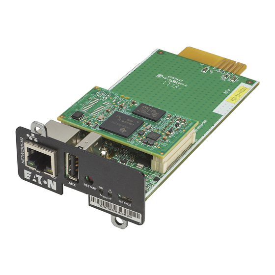
Front panel connectors and LED indicators 7 Information 7.1 Front panel connectors and LED indicators Name Description Network connector Ethernet port Network speed LED Flashing green sequences: • 1 flash — Port operating at 10Mbps • 2 flashes — Port operating at 100Mbps •... -
Page 211: Specifications/Technical Characteristics
Specifications/Technical characteristics Boot LEDs Solid green and flashing red — Network Module is starting boot sequence. Settings/UPS data Configuration port. connector Access to Network Module’s web interface through RNDIS (Emulated Network port). Access to the Network Module console through Serial (Emulated Serial port). 7.2 Specifications/Technical characteristics Physical characteristics Dimensions (wxdxh) -
Page 212: Default Settings And Possible Parameters
Default settings and possible parameters 7.3 Default settings and possible parameters 7.3.1 Settings Default settings and possible parameters - General Default setting Possible parameters System details Location — empty Location — 31 characters maximum Contact — empty Contact — 255 characters maximum System name — empty System name —... - Page 213 Default settings and possible parameters SMTP server authentication — disabled SMTP server authentication — disable/enable (Username/Password — 128 characters maximum) Port — 25 Port — x-xxx Default sender address — device @networkcard.com Sender address — 128 characters maximum Hide IP address from the email body — disabled Hide IP address from the email body —...
- Page 214 Default settings and possible parameters Default settings and possible parameters - Remote users Default setting Possible parameters LDAP Configure Configure • Active – No • Active – No/yes • Security • Security SSL – SSL SSL – None/Start TLS/SSL Verify server certificate –...
- Page 215 Default settings and possible parameters RADIUS Configure Configure • Active – No • Active – Yes/No • Retry number – 0 • Retry number – 0 to 128 • Primary server • Primary server Name – blank Name – 128 characters maximum Secret –...
- Page 216 Default settings and possible parameters Default settings and possible parameters - Network & Protocol Default setting Possible parameters IPV4 Mode — DHCP Mode — DHCP/Manual (Address/Netmask/Gateway) IPV6 Enable — checked Enabled — Active/Inactive Mode — DHCP Mode — DHCP/Manual (Address/Prefix/Gateway) DNS/DHCP Hostname —...
- Page 217 Default settings and possible parameters Using unicode byte order mask (BOM) – disable/ enable Default settings and possible parameters - SNMP Default setting Possible parameters SNMP Activate SNMP — disabled Activate SNMP — disable/enable Port — 161 Port — x-xxx SNMP V1 — disabled SNMP V1 —...
- Page 218 Port — 502 Port — x-xxx Mapping configuration No mapping Name – 128 characters maximum Map – Eaton ModbusMS compatible Transport – RTU/TCP Device ID – from 1 to 247 Access – None/Read only/Read/Write Illegal read behaviour – Return exception/Return zeros Coil/register base address shift –...
-
Page 219: Meters
Default settings and possible parameters 7.3.2 Meters Default settings and possible parameters - Meters Default setting Possible parameters Meters/Logs Log measures every — 60s Log measures every — 3600s maximum 7.3.3 Sensors alarm configuration Default settings and possible parameters - Environment Alarm configuration Default setting Possible parameters Temperature... -
Page 220: User Profile
Default settings and possible parameters 7.3.4 User profile Default settings and possible parameters - User profile Default setting Possible parameters Profile Account details: Account details: • Full name — Administrator • Full name — 128 characters maximum • Email —... -
Page 221: Access Rights Per Profiles
Access rights per profiles 7.4 Access rights per profiles 7.4.1 Home Administrator Operator Viewer Home 7.4.2 Meters Administrator Operator Viewer Meters Battery health: Launch test/Abort Logs configuration 7.4.3 Controls Administrator Operator Viewer Control 7.4.4 Protection Administrator Operator Viewer Protection/Scheduled shutdowns Administrator Operator Viewer... -
Page 222: Settings
Access rights per profiles Environment/Information 7.4.6 Settings Administrator Operator Viewer General Administrator Operator Viewer Local users Administrator Operator Viewer Remote users Administrator Operator Viewer Network & Protocols Administrator Operator Viewer SNMP Administrator Operator Viewer Modbus* *for INDGW only Administrator Operator Viewer Certificate... -
Page 223: Legal Information
Access rights per profiles 7.4.8 Legal information Administrator Operator Viewer Legal information 7.4.9 Alarms Administrator Operator Viewer Alarm list Export Clear 7.4.10 User profile Administrator Operator Viewer User profile 7.4.11 Contextual help Administrator Operator Viewer Contextual help Full documentation 7.4.12 CLI commands Administrator Operator Viewer... -
Page 224: List Of Event Codes
List of event codes modbus_statistics* *for INDGW only Administrator Operator Viewer netconf (read-only) (read-only) Administrator Operator Viewer ping ping6 Administrator Operator Viewer reboot Administrator Operator Viewer save_configuration restore_configuration Administrator Operator Viewer sanitize Administrator Operator Viewer ssh-keygen Administrator Operator Viewer time (read-only) (read-only) - Page 225 List of event codes To retrieve System logs, navigate to Contextual help>>>Maintenance>>>System logs section and press the Download System logs button. Below codes are the one to be used to add "Exceptions on events notification" on email sending configurations. Some zeros maybe added in front of the code when displayed in emails or logs. 7.5.1.1 Critical Code Severity...
- Page 226 List of event codes 1000D00 Warning Settings restoration error logSystem.csv 7.5.1.3 Info Code Severity Log message File 0300D00 Notice User action - sanitization launched logSystem.csv 0A00500 Notice Network module sanitized logUpdate.csv 0A00900 Notice Network module bootloader upgrade success <f/w: xx.yy.zzzz> logUpdate.csv 0A00B00 Notice...
- Page 227 List of event codes 0100B00 Notice Syslog is stopping logSystem.csv 0100D00 Notice Network module is booting logSystem.csv 0100E00 Notice Network module is operating logSystem.csv 0100F00 Notice Network module is starting shutdown sequence logSystem.csv 0101000 Notice Network module is ending shutdown sequence logSystem.csv 0101400 Notice...
-
Page 228: Ups(Hid) Alarm Log Codes
List of event codes 7.5.2 UPS(HID) alarm log codes This table applies to all UPS except to the 9130 UPS. To retrieve Alarm logs, navigate to Contextual help>>>Alarms section and press the Download alarms button. Below codes are the one to be used to add "Exceptions on events notification" on email sending configurations. Some zeros maybe added in front of the code when displayed in emails or logs. - Page 229 List of event codes Critical Parallel negative power Parallel power OK Reduce output load Critical Calibration fault Calibration OK Service required Critical Load unprotected Load protected 7.5.2.2 Warning Code Severity Active message Non-active message Advice Warning On battery No more on battery Warning Fan fault Fan OK...
- Page 230 List of event codes Warning Max charger voltage Charger voltage OK Service required Warning Min charger voltage Charger voltage OK Service required Warning Battery fuse fault Battery fuse OK Service required Warning Battery fuse fault Battery fuse OK Service required Warning Battery low state of charge Battery state of charge OK...
- Page 231 List of event codes Warning Compatibility failure Compatibility OK Service required Warning Output over current No output over current Reduce output load Warning Output frequency out of range Output frequency in range Service required Warning Output voltage too high Output voltage OK Service required Warning Output voltage too low...
-
Page 232: 9130 Ups(Xcp) Alarm Log Codes
List of event codes 7.5.3 9130 UPS(XCP) alarm log codes Use this table for 9130 UPS. To retrieve Alarm logs, navigate to Contextual help>>>Alarms section and press the Download alarms button. Below codes are the one to be used to add "Exceptions on events notification" on email sending configurations. Some zeros maybe added in front of the code when displayed in emails or logs. - Page 233 List of event codes 2325 Critical Bypass overload No bypass overload 2328 Critical Bypass thermal overload Bypass thermal OK 2364 Critical Internal failure End of internal failure 2402 Critical Parallel UPS not compatible Parallel UPS compatibility OK 281E Critical Load unprotected - 7.5.3.2 Warning Code...
- Page 234 List of event codes 2225 Warning Parallel UPS redundancy lost Parallel UPS redundancy OK 2231 Warning DC bus unbalanced DC bus OK 2240 Warning Parallel UPS communication lost Parallel UPS communication OK 2306 Warning Bypass breaker open Bypass breaker closed 2326 Warning Bypass phase out range...
-
Page 235: Ats Alarm Log Codes
List of event codes 7.5.4 ATS alarm log codes To retrieve Alarm logs, navigate to Contextual help>>>Alarms section and press the Download alarms button. Below codes are the one to be used to add "Exceptions on events notification" on email sending configurations. Some zeros maybe added in front of the code when displayed in emails or logs. - Page 236 List of event codes 7.5.4.3 Good Alarms with a severity set as Good are not taken into account into the counter of active alarms. Code Severity Active message Non-active message Advice Good Source 1 used to power the load Source 1 not used to power the load - Good Source 2 used to power the load...
-
Page 237: Emp Alarm Log Codes
List of event codes 7.5.5 EMP alarm log codes To retrieve Alarm logs, navigate to Contextual help>>>Alarms section and press the Download alarms button. Below codes are the one to be used to add "Exceptions on events notification" on email sending configurations. Some zeros maybe added in front of the code when displayed in emails or logs. -
Page 238: Network Module Alarm Log Codes
List of event codes 7.5.6 Network module alarm log codes To retrieve Alarm logs, navigate to Contextual help>>>Alarms section and press the Download alarms button. Below codes are the one to be used to add "Exceptions on events notification" on email sending configurations. Some zeros maybe added in front of the code when displayed in emails or logs. -
Page 239: Snmp Traps
SNMP traps 7.5.6.2.3 Alarms Code Severity Active message Non-active message Advice 1302 Info Alarms: the number of alarms is Alarms: the number of alarms is It is recommended to high and above 5 000 back to normal Export and Clear the alarm log. -
Page 240: Ats Mib
SNMP traps Alarm oid at : Description when trap 3 Description when trap 4 .1.3.6.1.2.1.33.1.6.3.x .1.3.6.1.2.1.33.1.6.3.20 Communication lost Communication recovered .1.3.6.1.2.1.33.1.6.3.23 Shutdown imminent Shutdown canceled 7.6.1.2 Xups Mib traps This information is for reference only. Trap oid : Trap message at oid : .1.3.6.1.4.1.534.1.11.4.1.0.x .1.3.6.1.4.1.534.1.11.3.0 .1.3.6.1.4.1.534.1.11.4.1.0.3... -
Page 241: Sensor Mib
SNMP traps Trap oid : Trap description .1.3.6.1.4.1.534.10.2.10.x .1.3.6.1.4.1.534.10.2.10.1 Communication lost .1.3.6.1.4.1.534.10.2.10.2 Communication recovered .1.3.6.1.4.1.534.10.2.10.3 Output powered .1.3.6.1.4.1.534.10.2.10.4 Output not powered .1.3.6.1.4.1.534.10.2.10.5 Overload .1.3.6.1.4.1.534.10.2.10.6 No overload .1.3.6.1.4.1.534.10.2.10.7 Internal failure .1.3.6.1.4.1.534.10.2.10.8 No internal failure .1.3.6.1.4.1.534.10.2.10.9 Source 1 normal .1.3.6.1.4.1.534.10.2.10.10 Source 1 out of range .1.3.6.1.4.1.534.10.2.10.11 Source 2 normal .1.3.6.1.4.1.534.10.2.10.12... -
Page 242: Cli
CLI 7.7 CLI CLI can be accessed through: • • Serial terminal emulation (refer to section Servicing the Network Management Module>>>Installing the Network Module>>>Accessing the card through serial terminal emulation). It is intended mainly for automated configuration of the network and time settings of the network card. It can also be used for troubleshooting and remote reboot/reset of the network interface in case the web user interface is not accessible. -
Page 243: Get Release Info
CONTEXT SENSITIVE HELP [?] - Display context sensitive help. This is either a list of possible command completions with summaries, or the full syntax of the current command. A subsequent repeat of this key, when a command has been resolved, will display a detailed reference. ... -
Page 244: History
CLI 7.7.3.3 Specifics 7.7.3.4 Access rights per profiles Administrator Operator Viewer get release info 7.7.4 history 7.7.4.1 Description Displays recent commands executed on the card. 7.7.4.2 Help history <cr> Display the current session's command line history(by default display last commands) <Unsigned integer> Set the size of history list (zero means unbounded). - Page 245 7.7.5.2 Help Usage: ldap-test <command> [OPTION]... Test LDAP configuration. Commands: ldap-test -h, --help, Display help page ldap-test --checkusername <username> [--primary|--secondary] [-v] Check the user can be retrieve from the LDAP server <username> Remote username to test --primary Force the test to use primary server (optional) --secondary Force the test to use secondary server (optional)
-
Page 246: Logout
CLI 7.7.6 logout 7.7.6.1 Description Logout the current user. 7.7.6.2 Help logout <cr> logout the user 7.7.6.3 Specifics 7.7.6.4 Access rights per profiles Administrator Operator Viewer logout 7.7.7 maintenance 7.7.7.1 Description Creates a maintenance report file which may be handed to the technical support. 7.7.7.2 Help maintenance <cr>... -
Page 247: Modbus_Statistics
7.7.8.1 Description modbus_message_display restarts the server and displays Modbus message. This command allow you to verifiy that Modbus server is working as expected. 7.7.8.2 Help modbus_message_display --help Restart server and display modbus message Restart server and display modbus message 7.7.8.3 Specifics 7.7.8.4 Access rights per profiles Administrator Operator... -
Page 248: Netconf
CLI 7.7.9.3 Specifics 7.7.9.4 Access rights per profiles Administrator Operator Viewer modbus_statistics* *for INDGW only 7.7.10 netconf 7.7.10.1 Description Tools to display or change the network configuration of the card. 7.7.10.2 Help For Viewer and Operator profiles: netconf -h Usage: netconf [OPTION]... - Page 249 netconf -h Usage: netconf [OPTION]... Display network information and change configuration. -h, --help display help page -l, --lan display Link status and MAC address -d, --domain display Domain mode, FQDN, Primary and Secondary DNS -4, --ipv4 display IPv4 Mode, Address, Netmask and Gateway ...
-
Page 250: Ping And Ping6
CLI 7.7.10.3 Examples of usage -> Display Link status and MAC address netconf -l -> Set Auto negotiation to Link netconf -s auto -> Set custom hostname netconf -f hostname ups-00-00-00-00-00-00 -> Set Adress, Netmask and Gateway netconf -i manual 192.168.0.1 255.255.255.0 192.168.0.2 ->... -
Page 251: Reboot
7.7.11.3 Specifics 7.7.11.4 Access rights per profiles Administrator Operator Viewer ping ping6 7.7.12 reboot 7.7.12.1 Description Tool to Reboot the card. 7.7.12.2 Help Usage: reboot [OPTION] <cr> Reboot the card --help Display help --withoutconfirmation Reboot the card without confirmation 7.7.12.3 Specifics 7.7.12.4 Access rights per profiles Administrator Operator... -
Page 252: Sanitize
CLI 7.7.13.3 Examples of usage 7.7.13.3.1 From a linux host: Save over SSH: sshpass -p $PASSWORD ssh $USER@$CARD_ADDRESS save_configuration -p $PASSPHRASE> $FILE Restore over SSH: cat $FILE | sshpass -p $PASSWORD ssh $USER@$CARD_ADDRESS restore_configuration -p $PASSPHRASE 7.7.13.3.2 From a Windows host: Save over SSH: plink ... -
Page 253: Ssh-Keygen
7.7.15 ssh-keygen 7.7.15.1 Description Command used for generating the ssh keys. 7.7.15.2 Help ssh-keygen -h, --help Display help <cr> Renew SSH keys 7.7.15.3 Specifics 7.7.15.4 Access rights per profiles Administrator Operator Viewer ssh-keygen 7.7.16 time 7.7.16.1 Description Command used to display or change time and date. 7.7.16.2 Help For Viewer and Operator profiles: time -h... -
Page 254: Traceroute And Traceroute6
CLI time -h Usage: time [OPTION]... Display time and date, change time and date. -h, --help display help page -p, --print display date and time in YYYYMMDDhhmmss format -s, --set <mode> Mode values: - set date and time (format YYYYMMDDhhmmss) ... -
Page 255: Whoami
7.7.17.3 Specifics 7.7.17.4 Access rights per profiles Administrator Operator Viewer traceroute traceroute6 7.7.18 whoami 7.7.18.1 Description whoami displays current user information: • Username • Profile • Realm 7.7.18.2 Specifics 7.7.18.3 Access rights per profiles Administrator Operator Viewer whoami 7.7.19 email-test 7.7.19.1 Description mail-test sends test email to troubleshoot SMTP issues. -
Page 256: Systeminfo_Statistics
CLI 7.7.19.3 Specifics 7.7.19.4 Access rights per profiles Administrator Operator Viewer email-test 7.7.20 systeminfo_statistics 7.7.20.1 Description Displays the following system information usage: usage : % upSince : date since the system started total: MB free: MB used: MB tmpfs: temporary files usage (MB) Flash user data ... - Page 257 7.7.21.2 Help certificates <target> <action> <service_name> <target> : - local <action> : - print: provides a given certificate detailed information. - revoke: revokes a given certificate. - export: returns a given certificate contents. - import: upload a given certificate the server CSR. This will replace the CSR with the certificate given.
-
Page 258: Legal Information
Copyright © 2020 Eaton. This firmware is confidential and licensed under Eaton Proprietary License (EPL or EULA). This firmware is not authorized to be used, duplicated, or disclosed to anyone without the prior written permission of Eaton. Limitations, restrictions and exclusions of the Eaton applicable standard terms and conditions, such as its EPL and EULA, apply. -
Page 259: Acronyms And Abbreviations
Acronyms and abbreviations 7.9 Acronyms and abbreviations AC: Alternating current. ATS: Automatic transfer switch is an electrical switch that switches a load between two sources. AVR: Automatic Voltage Regulation provides stable voltage to keep equipment running in the optimal range. BMS: A Battery Management System is any electronic system that manages li-ion battery. bps: bit per second BOM: In Syslog, placing an encoded Byte Order Mark at the start of a text stream can indicates that the text is Unicode and identify the encoding scheme used. - Page 260 Acronyms and abbreviations MAC: A media access control address of a computer is a unique identifier assigned to network interfaces for communications at the data link layer of a network segment. MIB: A management information base is a database used for managing the entities in a communication network. Most often associated with the Simple Network Management Protocol (SNMP).
- Page 261 Acronyms and abbreviations Information – 261...
-
Page 262: Troubleshooting
Action not allowed in Control/Schedule/Power outage policy 8 Troubleshooting 8.1 Action not allowed in Control/Schedule/Power outage policy 8.1.1 Symptom Below message is displayed when you access the Control, Schedule or Power outage policy page. This action is not allowed by the UPS. To enable it, please refer to the user manual of the UPS and its instructions on how to configure the UPS settings and allow remote commands. -
Page 263: Action
EMP detection fails at discovery stage 8.3.3 Action In the server system BIOS, change the setting for Automatic Power ON to "Enabled". 8.4 EMP detection fails at discovery stage In the Network Module, in Contextual help>>>Environment>>>Commissioning/Status, EMPs are missing in the Sensor commissioning table. -
Page 264: How Do I Log In If I Forgot My Password
How do I log in if I forgot my password? Refer to the section Contextual help>>>Maintenance>>>Services>>>Reboot. 2- Launch the discovery. 8.5 How do I log in if I forgot my password? 8.5.1 Action • Ask your administrator for password initialization. • If you are the main administrator, your password can be reset manually by following steps described in the Servicing the Network Management Module>>>Recovering main administrator password. -
Page 265: Action #2
During the selected timeframe, new agent connections to the Network Module are automatically trusted and accepted. STEP 4: Action on the agent (IPP/IPM) while the time to accepts new agents is running on the Network Module Remove the Network module certificate file(s) *.0 that is (are) located in the folder Eaton\IntelligentPowerProtector\configs\tls. 8.7 LDAP configuration/commissioning is not working Refer to the section Servicing the Network Management Module>>>Commissioning/Testing... - Page 266 The alarm list has been cleared after an upgrade 8.9.2 Symptom SNMPv3 connectivity is not properly working after a restore settings on a 1.7.0 version or above. 8.9.3 Cause The SNMPv3 was configured prior to 1.7.0. In that case, SNMPv3 configuration is not well managed by the Save and by the Restore settings. 8.9.4 Action Reconfigure your SNMPv3 users and passwords on versions 1.7.0 or above and Save the settings.
- Page 267 Web user interface is not up to date after a FW upgrade 8.11.2 Action Recover the IP address and connect to the card. Refer to Installing the Network Management Module>>>Accessing the Network Module>>>Finding and setting the IP address section. 8.12 Web user interface is not up to date after a FW upgrade 8.12.1 Symptom After an upgrade: •...
Need help?
Do you have a question about the Network-M2 and is the answer not in the manual?
Questions and answers