
Related Manuals for Eaton Modbus MS Card


Summary of Contents for Eaton Modbus MS Card
- Page 1 Modbus MS Card User manual – User Manual Modbus MS Card Page 34009048XT_EN/AD 1/55...
-
Page 2: Table Of Contents
ATA FOR ULSAR 6.2.1 Status table 6.2.2 Measurements table MX 4000 / 5000 / 10000 ATA FOR ULSAR 6.3.1 Status table 6.3.2 Measurements table 15 / 20 ATA FOR ULSAR FRAME – User Manual Modbus MS Card Page 34009048XT_EN/AD 2/55... - Page 3 Status table 6.10.2 Measurements table 6.11 ENERIC 6.11.1 Status table 6.11.2 Measurements table 6.12 ENSOR DATA 6.12.1 Status table 6.12.2 Measurements table 6.12.3 Read of the personalization table 6.13 THER DATA GLOSSARY – User Manual Modbus MS Card Page 34009048XT_EN/AD 3/55...
-
Page 4: Introduction
1 Introduction The embedded application of the Modbus MS Card (previously INMC) is based on the Network MS Card (previously NMC). For all common features, the user manual is the same as NMC (see reference below). In this document, only JBUS/MODBUS requirements are described. -
Page 5: Presentation
2.1 Overview 2.2 Functions The Modbus MS Card provides the same functions than the Network MS card described in the previous section of this document. The adding function consists to provide UPS (Uninterruptible Power Supply) data (states and measures) to be sent a computer system. -
Page 6: Technical Characteristics
(Tx) or - Tx on pin 3 - Tx on pin 3 receive data (Rx) RS485 link - Termination - No termination - With or without (2 or 4 wires) – User Manual Modbus MS Card Page 34009048XT_EN/AD 6/55... -
Page 7: Installation
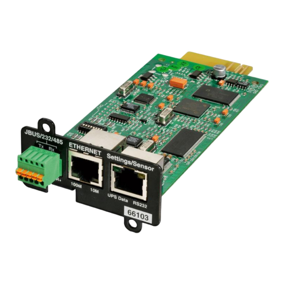
The next figure shows the details of the connection in RS232 mode: Pin number Function JBUS/232/485 ETHERNET Settings/Sensor Received data (input) OV T+ T- R+ R- 100M UPS Data RS232 Not connected XXXXXXXXXXXX 66103 Transmitted data (output) Not connected Signal Ground – User Manual Modbus MS Card Page 34009048XT_EN/AD 7/55... -
Page 8: Rs485 Link Configuration And Connection
3.2 RS485 link configuration and connection 3.2.1 RS485 connection Normally, the master of the network sets the polarity of the line. The Modbus MS card is a slave equipment and don’t have polarisation resistor. The two ends of the line must be terminated. Allow for 1 or 2 terminators to avoid mismatching the line when any equipment at the end of the line is disconnected. - Page 9 4: connection T- to R- (2 wires configuration) if set to ON 5: connection T+ to R+ (2 wires configuration) if set to ON 6: reserved 7: reserved 8: link termination between R+ and R- if set to ON – User Manual Modbus MS Card Page 34009048XT_EN/AD 9/55...
-
Page 10: Rs485 Link Configuration For 2 Wires Connexion
3.2.2 RS485 link configuration for 2 wires connexion Set the SA2 switches like below to set the RS485 mode: Set the SA1 switches to select the two wires configuration with no termination: – User Manual Modbus MS Card Page 34009048XT_EN/AD 10/55... - Page 11 Set the SA1 switches to select the two wires configuration with termination: The next figure gives a typical bus structure in the two wires configuration: – User Manual Modbus MS Card Page 34009048XT_EN/AD 11/55...
-
Page 12: Rs485 Link Configuration For 4 Wires Connexion
3.2.3 RS485 link configuration for 4 wires connexion Set the SA2 switches like below: Set the SA1 switches to select the four wires configuration with no termination: – User Manual Modbus MS Card Page 34009048XT_EN/AD 12/55... - Page 13 Set the SA1 switches to select the four wires configuration with termination: The next figure gives a typical bus structure in the four wires configuration: – User Manual Modbus MS Card Page 34009048XT_EN/AD 13/55...
-
Page 14: Configuration Of The Jbus/Modbus Communication Parameters
Connect the card to a computer equipped with a Hyper terminal type emulator. The serial link must be set at 9600 baud, 8 bits, no parity, 1 stop bit, and without flow control. Check that UPS power is on. Enter the admin password (not upgradable). – User Manual Modbus MS Card Page 34009048XT_EN/AD 14/55... -
Page 15: Choice 1: Display Jbus Settings
The next menu appears: ----------------------------------------------------------------------------- EATON NETWORK MANAGEMENT – JBUS CARD ----------------------------------------------------------------------------- 1 : Reset 2 : Network configuration 3 : Set Login Password to Default 4 : Return to Default Configuration 5 : Jbus configuration 6 : Sensor configuration... -
Page 16: Choice 3: Display Jbus Diagnostics
Returns to the Jbus default configuration (0x01, 9600, 8, 1, none) Wait during Jbus configuration returns to default ... Jbus Configuration has been set to default one. 3.3.6 Choice 6: Display Jbus frames Enable the display of the Jbus frames: – User Manual Modbus MS Card Page 34009048XT_EN/AD 16/55... - Page 17 Send : 01 81 02 c1 91 Recv : 01 03 00 62 00 64 e5 ff Send : 01 03 c8 00 00 00 00 00 00 00 00 00 00 00 00 00 ... – User Manual Modbus MS Card Page 34009048XT_EN/AD 17/55...
-
Page 18: Additional Web
4 Additional Web pages The Modbus MS card parameters could be set through the next page: – User Manual Modbus MS Card Page 34009048XT_EN/AD 18/55... -
Page 19: Menu/Cli Interfaces
Stop bit Parity 5.1 Menu interface 5.1.1 Main menu This screen is the main screen displayed when the connection is established. ------------------------------------------------------------------------ EATON NETWORK MANAGEMENT- JBUS CARD Main menu ------------------------------------------------------------------------ 1 : Reset 2 : Network settings 3 : Trap receivers... - Page 20 ------------------------------------------------------------------------ EATON NETWORK MANAGEMENT - JBUS CARD Modbus/Jbus settings ------------------------------------------------------------------------ 1 : Serial link 2 : Diagnostic counters 0 : Exit ---------------------------------------------------------------------- ------------------------------------------------------------------------ EATON NETWORK MANAGEMENT - JBUS CARD Modbus/Jbus settings – Serial link ------------------------------------------------------------------------ 1 : Slave address [1]...
-
Page 21: Command Line Interface
: SlaveAddress = xxx (1..255) Speed = xxxx (1200|2400|4800|9600|19200|38400) DataBit = x StopBit = x (1|2) Parity = x (0=None, 1=Odd, 2=Even) Examples #> setJBUS Speed = 19200 Parity = 2 – User Manual Modbus MS Card Page 34009048XT_EN/AD 21/55... -
Page 22: Getjbuscounter
BusMessage CRCError SlaveException SlaveMessage SlaveNoResponse SlaveNAK SlaveBusy Overrun SlaveCorrectResponse Examples #> getJBUSCounter All 5.2.4 “setJBUSCounter” Purpose Reset of the JBUS diagnostics counters Syntax setJBUSCounter [option1] options : Examples #> setJBUSCounter RAZ – User Manual Modbus MS Card Page 34009048XT_EN/AD 22/55... -
Page 23: Jbus Table
Mains 1 voltage out of tolerance Mains 1 frequency out of tolerance Bypass status Charger general fault not in Battery charge in charge 1 & 3 charge Converter fault Inverter fault – User Manual Modbus MS Card Page 34009048XT_EN/AD 23/55... -
Page 24: Measurements Table
Output active power Output apparent power % output load level Power factor (Cos PHI) Mains 1 frequency Output frequency Battery backup time Battery charging level U mains 1 Nominal voltage of battery element – User Manual Modbus MS Card Page 34009048XT_EN/AD 24/55... -
Page 25: Data For Pulsarm 2200 / 3000
Output on bypass Mains 2 frequency out of tolerance Mains 2 voltage out of tolerance Phase M2 out of tolerance Charger general fault Battery charge 1 & 3 Converter fault Inverter major fault – User Manual Modbus MS Card Page 34009048XT_EN/AD 25/55... -
Page 26: Measurements Table
Output active power Output apparent power % output load level Power factor x 100 Mains 1 frequency Output frequency Battery backup time Battery charging level U mains 1 Nominal voltage of battery element – User Manual Modbus MS Card Page 34009048XT_EN/AD 26/55... -
Page 27: Data For Pulsar Mx 4000 / 5000 / 10000
Mains 2 internal fault absent present Charger general fault Battery charge 1 & 3 Converter fault Inverter major fault Inverter overload Inverter thermal overload Inverter limitation UPS fuse fault absent present – User Manual Modbus MS Card Page 34009048XT_EN/AD 27/55... -
Page 28: Measurements Table
Output apparent power % output load level Power factor (Cos PHI) Mains 1 frequency Mains 2 frequency Output frequency Battery backup time Battery charging level U mains 1 Nominal voltage of battery element – User Manual Modbus MS Card Page 34009048XT_EN/AD 28/55... -
Page 29: Data For Pulsar Mx Frame
Phase M2 out of tolerance Mains 2 internal fault absent present Charger general fault Battery charge 1 & 3 Inverter major fault Inverter overload Inverter thermal overload Inverter limitation UPS fuse fault absent present – User Manual Modbus MS Card Page 34009048XT_EN/AD 29/55... -
Page 30: Modular Fault Table
General alarm Absent Present Fan failure Absent Present Internal communication fault Absent Present Inverter thermal overload Absent Present Inverter fault Absent Present Inverter fuse blown Absent Present Load short circuit Absent Present – User Manual Modbus MS Card Page 34009048XT_EN/AD 30/55... - Page 31 General alarm Absent Present Fan failure Absent Present Internal communication fault Absent Present Inverter thermal overload Absent Present Inverter fault Absent Present Inverter fuse blown Absent Present Load short circuit Absent Present – User Manual Modbus MS Card Page 34009048XT_EN/AD 31/55...
-
Page 32: Measurements Table
% output load level Peak factor phase 1 x 100 Peak factor phase 2 x 100 Peak factor phase 3 x 100 Power factor x 100 Mains 1 frequency Mains 2 frequency – User Manual Modbus MS Card Page 34009048XT_EN/AD 32/55... - Page 33 Description of the physical quantity Word (hex) Output frequency Battery backup time Battery charging level U mains 1 (phase 1) U mains 1 (phase 2) U mains 1 (phase 3) Nominal voltage of battery element – User Manual Modbus MS Card Page 34009048XT_EN/AD 33/55...
-
Page 34: Data For Eaton 93E And Eaton 93Pm
6.5 Data for Eaton 93E and Eaton 93PM 6.5.1 Status table Status description Status to 0 Status to 1 Word (hex) Load protected UPS coupled Unit general alarm UPS in backup Battery low warning Low battery Operation on static switch... -
Page 35: Measurements Table
W of KW U12 mains 1 U23 mains 1 U31 mains 1 U mains 2 (phase 1) U mains 2 (phase 2) U mains 2 (phase 3) U12 mains 2 U23 mains 2 – User Manual Modbus MS Card Page 34009048XT_EN/AD 35/55... - Page 36 Output frequency Battery backup time U mains 1 (phase 1) U mains 1 (phase 2) U mains 1 (phase 3) Nominal value apparent power VA or KVA Nominal voltage of battery element – User Manual Modbus MS Card Page 34009048XT_EN/AD 36/55...
-
Page 37: Data For Eaton 5Px And Eaton 5P
6.6 Data for Eaton 5PX and Eaton 5P 6.6.1 Status table Status description Status to 0 Status to 1 Word (hex) Load protected UPS coupled Unit general alarm UPS in backup Battery low warning Low battery Communication fault absent present... -
Page 38: Measurements Table
% output load level Power factor (Cos PHI) Mains 1 frequency Output frequency Battery backup time Battery charging level U mains 1 Nominal value apparent power VA or KVA Nominal voltage of battery element – User Manual Modbus MS Card Page 34009048XT_EN/AD 38/55... -
Page 39: Data For Eaton 9E
6.7 Data for Eaton 9E 6.7.1 Status table Status description Status to 0 Status to 1 Word (hex) Load protected UPS coupled Unit general alarm UPS in backup Battery low warning Low battery Operation on static switch Communication fault absent... -
Page 40: Measurements Table
Battery backup time Battery charging level U mains 1 (phase 1) U mains 1 (phase 2) U mains 1 (phase 3) Nominal value apparent power VA or KVA Nominal voltage of battery element – User Manual Modbus MS Card Page 34009048XT_EN/AD 40/55... -
Page 41: Data For Eaton 9Px And Eaton 9Sx Single Phase
6.8 Data for Eaton 9PX and Eaton 9SX Single phase 6.8.1 Status table Status description Status to 0 Status to 1 Word (hex) Load protected UPS coupled Unit general alarm Configuration firmware fault UPS in backup Battery low warning Low battery... -
Page 42: Measurements Table
Power factor x 100 Mains 1 frequency Mains 2 frequency Output frequency Battery backup time Battery charging level U mains 1 Nominal value apparent power VA or KVA Nominal voltage of battery element – User Manual Modbus MS Card Page 34009048XT_EN/AD 42/55... -
Page 43: Data For Eaton 9Px Three Phase Input
6.9 Data for Eaton 9PX Three phase Input 6.9.1 Status table Status description Status to 0 Status to 1 Word (hex) Load protected UPS coupled Unit general alarm Configuration firmware fault UPS in backup Battery low warning Low battery Operation on static switch... -
Page 44: Measurements Table
Battery backup time Battery charging level U mains 1 (phase 1) U mains 1 (phase 2) U mains 1 (phase 3) Nominal value apparent power VA or KVA Nominal voltage of battery element – User Manual Modbus MS Card Page 34009048XT_EN/AD 44/55... -
Page 45: Data For Eaton 9Px Split Phase
6.10 Data for Eaton 9PX Split phase 6.10.1 Status table Status description Status to 0 Status to 1 Word (hex) Load protected UPS coupled Unit general alarm Configuration firmware fault UPS in backup Battery low warning Low battery Operation on static switch... -
Page 46: Measurements Table
Mains 2 frequency Output frequency Battery backup time Battery charging level U mains 1 (phase 1) U mains 1 (phase 2) Nominal value apparent power VA or KVA Nominal voltage of battery element – User Manual Modbus MS Card Page 34009048XT_EN/AD 46/55... -
Page 47: Generic Ups
Circuit breaker Q1 status open close Mains 1 voltage out of tolerance Mains 1 fuse fault Charger over temperature fault absent present Mains 1 frequency out of tolerance Redundancy lost Maintenance position – User Manual Modbus MS Card Page 34009048XT_EN/AD 47/55... - Page 48 Inverter major fault Inverter overload Inverter thermal overload Inverter limitation UPS fuse fault absent present Over temperature absent present Short circuit Output frequency out of range Electronic power supply fault – User Manual Modbus MS Card Page 34009048XT_EN/AD 48/55...
-
Page 49: Measurements Table
Output apparent power (phase 3) Output total active power Output total apparent power % output load level Peak factor phase 1 x 100 Peak factor phase 2 x 100 Peak factor phase 3 x 100 – User Manual Modbus MS Card Page 34009048XT_EN/AD 49/55... - Page 50 Battery backup time Battery charging level U mains 1 (phase 1) U mains 1 (phase 2) U mains 1 (phase 3) Nominal value apparent power VA or KVA Nominal voltage of battery element – User Manual Modbus MS Card Page 34009048XT_EN/AD 50/55...
-
Page 51: Sensor Data
Input 2 alarm Alarm : humidity too low Alarm : humidity too high Alarm : temperature too low Alarm : temperature too high Communication fault Input 1 open close Input 2 open close – User Manual Modbus MS Card Page 34009048XT_EN/AD 51/55... -
Page 52: Measurements Table
Input 1 changing date (MSB) in Unix timestamp Input 1 changing date (LSB) in Unix timestamp Input 2 changing date (MSB) in Unix timestamp Input 2 changing date (LSB) in Unix timestamp – User Manual Modbus MS Card Page 34009048XT_EN/AD 52/55... -
Page 53: Read Of The Personalization Table
Inputs call mask – input 1 open shutdown Inputs call mask – input 2 close shutdown Inputs call mask – input 2 open shutdown Input 1 identification 336 - 343 Input 2 identification 344 - 351 – User Manual Modbus MS Card Page 34009048XT_EN/AD 53/55... -
Page 54: Other Data
“Eaton” Manufacturer name 1A8 – 1AF “Pulsar” Product name 1B0 – 1B7 “700” UPS model 1B8 – 1BF “AN2E49008” Serial number 1C0 – 1C7 Part number 1C8 – 1CF Reference number – User Manual Modbus MS Card Page 34009048XT_EN/AD 54/55... -
Page 55: Glossary
7 Glossary – User Manual Modbus MS Card Page 34009048XT_EN/AD 55/55...
Need help?
Do you have a question about the Modbus MS Card and is the answer not in the manual?
Questions and answers