
Related Manuals for Eaton Network Management Card


Summary of Contents for Eaton Network Management Card
- Page 1 Network Management Card (Network-MS) User manual Network Management Card Page – User Manual 34003991XT_EN/EF 1/127...
-
Page 2: Table Of Contents
Your network is not equipped with a DHCPv4 server 3.1.3 IPv6 Parameters EST AFTER CONFIGURATION SUPERVISION AND ADMINISTRATION BY BROWSER PTIMISING THE PERFORMANCE OF YOUR BROWSER 4.2.1 UPS properties page 4.2.2 On-line help Network Management Card Page – User Manual 34003991XT_EN/EF 2/127... - Page 3 Environment Status 4.5.3 Environment Settings 4.5.4 SERVER PROTECTION UP OF THE SHUTDOWN PARAMETERS 5.1.1 Shutdown criteria managed by the Network Management Card 5.1.2 Controlled outlets 5.1.3 Protection of a server connected to a controlled outlet HE DIFFERENT SERVER AND SHUTDOWN SEQUENCES 5.2.1...
- Page 4 Choice 2: Modify IPv4 Network settings 7.2.3 Choice 3: Set Ethernet speed 3: L HOICE OST PASSWORD OGIN ASSWORD TO EFAULT 4: R HOICE ETURN TO EFAULT ONFIGURATION APPENDIX ABLES OF ALARMS AND EVENTS Network Management Card Page – User Manual 34003991XT_EN/EF 4/127...
- Page 5 Table of alarms 8.1.2 Table of UPS events 8.1.3 Table of system alarms SNMP OBJECTS 8.2.1 IETF MIB 8.2.2 EATON Pulsar MIB (ex MGE) 8.2.3 TRAPS table: (1.3.6.1.4.1.705.1.11) 8.2.4 EATON Powerware MIB GLOSSARY Network Management Card Page – User Manual 34003991XT_EN/EF...
-
Page 6: Eaton Network Solution
Carries out automatic shutdown of computer systems, Monitors and controls all the UPSs connected to the network. EATON Network Solution provides 3 main functions: Supervision of the UPSs over the Network: Web browser, Intelligent Power Manager, or SNMP Network Management System (NMS). -
Page 7: Connecting The Ups To The Ethernet Network
Connecting the UPS to the Ethernet network This function can be performed through network Cards inserted in the UPS (Network Management Card). Also a software "agent" running on a nearby PC that is called the IPP Shutdown controller feature can be used. -
Page 8: Supervision Of The Upss Over The Network
Company’s standard Network Management System (HP-Openview, CA Unicenter, HP Insight Manager, IBM Tivoli Netview) To simplify integration of EATON UPSs, use one of the Network Management System Kits for EATON devices. These kits are available on the Software Suite CD-ROM or on the http://powerquality.eaton.com... - Page 9 Install and configure the protection application on all machines that are to be protected by the UPS: Intelligent Power Protector for EATON Pulsar series UPS: The software components for each platform and the user manuals are on the Software Suite CD or available at http://powerquality.eaton.com...
-
Page 10: Presentation Of The Network Management Card (Nmc)
NMC also supplies alarms to the Intelligent Power Protector in order to trigger shutdowns or manage other automatic actions on protected servers. 1.2.2 Direct sending of E-mail When a UPS event occurs, the Network Management Card can directly notify up to 4 addresses by e-mail. (see E-mail Notification and E-mail message settings) -
Page 11: Sending Text Messages (Sms)
Environment Sensor enables measurement of temperature and humidity around the UPS, allows managing external alarms via 2 dry contacts and notification of alarms according to pre-programmed thresholds. (see Environment Status Environment Configuration) Network Management Card Page – User Manual 34003991XT_EN/EF 11/127... -
Page 12: Technical Data
The NMC Card can be easily installed while the UPS is online, maintaining the highest system availability The user can configure the card with one of the following means: Web browser Telnet/SSH/CLI Local serial link (network parameters) BOOTP/DHCP (network parameters). Network Management Card Page – User Manual 34003991XT_EN/EF 12/127... -
Page 13: Administration
TRAP SNMP in/out NSM in connected mode in/out 5000 NSM in UDP broadcast mode in/out 4679, 4680 1.3.6 Environment sensor Temperature measurement from 0 to 70 °C with +/- 1 °C accuracy. Network Management Card Page – User Manual 34003991XT_EN/EF 13/127... -
Page 14: Mib (Management Information Base)
1.3.7 MIB (Management Information Base) The card is Compatible with following MIBs: MIB II (RFC 1213) Internet Engineering Task Force (IETF) Standard UPS MIB (RFC 1628) EATON Pulsar MIB (ex MGE) V1.7 EATON Powerware MIB (PowerMib) See the Chapter appendix... -
Page 15: Default Parameters
Read-Only Password readuser 8 characters minimum, 24 characters maximum Read-Write User wirteuser 1 character minimum, 32 characters maximum Read-Write Security Level Authentification&Privacy None, Authentification, Authentification&Privacy Read-Write Password writeuser 8 characters minimum, Network Management Card Page – User Manual 34003991XT_EN/EF 15/127... - Page 16 Synchronise manually NTP server ntpserver 49 characters maximum Serial link Speed 9600 baud Not configurable Data bits Not configurable Stop bits Not configurable Parity without Not configurable Flow control without Not configurable Network Management Card Page – User Manual 34003991XT_EN/EF 16/127...
-
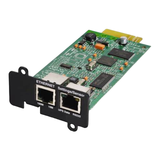
Page 17: Installation
2 Installation 2.1 Unpacking and check on contents The installation kit contents: A Network Management Card (Network-MS) A serial communication cable for configuration ( 34003918 Installation manual ( 34003905 2.2 Indications Network Management Card Page – User Manual 34003991XT_EN/EF 17/127... -
Page 18: Installation In The Ups
Communication with the Environment Sensor (option). 2.3 Installation in the UPS The Network Management Card (Network-MS) is "hot-swappable". It can be installed in all UPSs of the EATON Pulsar series or EATON Powerware series equipped with a Minislot without having to shut it down. -
Page 19: Sensor Installation (Option)
2.4 Sensor installation (option) The Environment sensor is available as an option for the Network Management Card and is available from EATON (EMP). The sensor allows remote monitoring of the UPS's environment through regular measurements: temperature, humidity, status of two external contacts. It also enables notification of alarms (e-mail, trap SNMP) according to pre-programmed thresholds. -
Page 20: Configuration
Flow control: none "Locally reproduce the characters entered" option: deactivated. Enter admin. The main menu is displayed: ----------------------------------------------------------------------------- EATON NETWORK MANAGEMENT CARD ----------------------------------------------------------------------------- 1 : Reset 2 : Network configuration 3 : Set Login Password to Default 4 : Return to Default Configuration... -
Page 21: Your Network Is Equipped With A Dhcpv4 Server
Note: As long as the card is not connected to the network, it continuously attempts to make connection. Once the connection has been established, the operational mode presented in the table above becomes effective. Network Management Card Page – User Manual... -
Page 22: Your Network Is Not Equipped With A Dhcpv4 Server
3.2 Test after configuration To check that the Network Management Card is operational after installation and configuration: From a station connected to the same subnet as the card, open a web browser and enter the IP address of the... -
Page 23: Supervision And Administration By Browser
To view status changes on the UPS in real time, the browser must be configured so that it automatically refreshes all the objects on the current page. Example on IE 8: Tools / Internet Options / General / Parameters menu, tick Every time this page is visited and validate. Network Management Card Page – User Manual 34003991XT_EN/EF... -
Page 24: Ups
The UPS Properties page shows an image and generic name of the UPS range. You can customize Computer Room to name the location of your system (see “System Settings”). mode. An animated diagram displays for online UPSs showing an overview of the current UPS operating Network Management Card Page – User Manual 34003991XT_EN/EF... - Page 25 UPS with automatic bypass UPS with automatic and manual bypass UPS without automatic bypass Note: In case of loss of communication with the UPS, all the elements of the synoptic are grey. Network Management Card Page – User Manual 34003991XT_EN/EF...
- Page 26 Yellow DC to AC converter powered by battery Gray DC to AC converter not powered by battery DC to AC Converter Input flow: Yellow Energy flow present Gray No energy flow Network Management Card Page – User Manual 34003991XT_EN/EF 26/127...
- Page 27 Green Powered Gray Not powered Internal failure AC Manual Bypass Flow: Yellow Energy flow present Gray No energy flow AC Manual Bypass Status: Green / Gray Open Red / Yellow Closed Network Management Card Page – User Manual 34003991XT_EN/EF 27/127...
- Page 28 AC Output Flow: Yellow Energy flow present Gray No energy flow (or Load = 0%) AC Output: Green Load protected Load not protected Network Management Card Page – User Manual 34003991XT_EN/EF 28/127...
- Page 29 Place the cursor over an element in the diagram to display the UPS measurement detail (see Figure). These measurements are available for Input, Battery, Output, and Bypass mode. The available measurements depend on the UPS range Network Management Card Page – User Manual...
-
Page 30: Ups Status
Past Hour Average Consumption: indicates the average consumption on the last hour of each output. The sum of these 3 consumptions is also given. Note: These data are only available with UPS Eaton 5PX. The displaying is the following : The various icons showing the status of the UPS outputs are:... - Page 31 4.2.1.3 Viewing the modules (Only with Eaton MX Frame UPS) Click on UPS Modules scroll list to view the information about the UPS modules. Active sources: x UPS + y UPS redundant : x indicates the minimal number of UPS necessary to power the load, y indicates the number of UPS in redundancy.
- Page 32 When the module is working properly with no alarms, the icon is not reactive, otherwise it is reactive and clicking on it makes the page Alarm Table appear. Output load level: Value of the percentage of load at module output Battery load level: Percentage of charge available in the battery module Network Management Card Page – User Manual 34003991XT_EN/EF...
-
Page 33: Viewing The Alarms
Click on "Alarm Table" scroll list to view the list of current alarms. The table of managed alarms is included in the appendix. The level of the alarms appears like below: Critical Warning Unknown Alarm table for standard UPS: Network Management Card Page – User Manual 34003991XT_EN/EF 33/127... - Page 34 Alarm table for modular UPS: Network Management Card Page – User Manual 34003991XT_EN/EF 34/127...
- Page 35 4.2.1.5 Viewing the “About your UPS” page Click on About your UPS scroll list to view the information about the UPS and the card. Network Management Card Page – User Manual 34003991XT_EN/EF 35/127...
-
Page 36: On-Line Help
On-line contextual help in English is available at the top of each page by clicking on the Help link, which is always located on the top right corner. The navigation menu of the on-line help is identical to that of the card's pages. The Help page always opens a new window. Network Management Card Page – User Manual... -
Page 37: Logging In
After three unsuccessful login attempts, you must refresh the browser. Both the user name and password fields are encrypted with an MD5 type algorithm, ensuring total security. “Set Login Password to Default” to reset the password. Network Management Card Page – User Manual 34003991XT_EN/EF... -
Page 38: Ups Control
Finally, the restart sequence is launched at the end of the time delay specified in the "Toggle duration" parameter. The output status is updated. Network Management Card Page – User Manual... - Page 39 Delayed On: This is the same switch on sequence as for the "Immediate On" command, but postponed by the number of seconds programmed in the "On Delay" parameter. The Save button saves the Off Delay, Toggle duration and On Delay parameters on the card. Network Management Card Page – User Manual...
-
Page 40: Ups Weekly Schedule Programming
UPS output is switched off. Up to 7 UPS shutdown sequences can be programmed in one week, with a minimum shutdown delay of 30 minutes. The On / Off sequences are valid only if the card's time has been properly set. Network Management Card Page – User Manual... -
Page 41: Shutdown Parameters
The Output column enables each outlet to be named (maximum 20 characters). Note As priority is given to the main outlet, the card cannot supply the controlled outlets when main outlet power is off. Network Management Card Page – User Manual... - Page 42 Switch On after (from 0 to 99999, default 65535) is the period between main output startup and startup of the relevant programmable outlet, therefore outlet startup can be delayed in relation to the main output. Important: Certain UPSs do not support this option Network Management Card Page – User Manual...
-
Page 43: Measurements
Save Log enables all saved values to be opened or saved in CSV format. (compatible with Excel type spreadsheets) Clear Log enables deletion of all records. Enter the login/password to validate this action. Network Management Card Page – User Manual... -
Page 44: Event Log
Clear log enables deletion of all records. The administrator must enter his/her login / password to validate this action. The card can save 435 events. The table of managed alarms is included in the appendix Network Management Card Page – User Manual 34003991XT_EN/EF... -
Page 45: System Log
Clear log enables deletion of all records. The administrator must enter his/her login / password to validate this action. The card can save 435 events. The table of managed alarms is included in the appendix. Network Management Card Page – User Manual... -
Page 46: Notification
Recipient: (Field is limited to 99 characters) this is the e-mail address of the person or department to receive the e-mail. The default value is : recipientx@domain.com eNotify: This parameter enables communications to the Eaton eNotify Monitoring and Diagnostics Service. NOTE: Available only for customers with a valid eNotify Service Contract. ω... - Page 47 Set Default. Email Message Settings: access to the message configuration page Network Settings: enables the name of the SMTP server to be entered. See page Network Management Card Page – User Manual 34003991XT_EN/EF...
-
Page 48: E-Mail Message Settings
- The date and time of the event, as saved in the log. - URL of the card, enabling a direct link with the card to be established. - Attachments, as configured for the e-mail recipients. - Duplication of the subject, as configured. Network Management Card Page – User Manual 34003991XT_EN/EF... - Page 49 Network Management Card Page – User Manual 34003991XT_EN/EF 49/127...
-
Page 50: Configuration
Network settings Click on Network in the menu. This menu enables the administrator to configure the network parameters of the card and authorisation of the remote upgrade of the embedded system. Network Management Card Page – User Manual 34003991XT_EN/EF 50/127... - Page 51 If Auto Config is not enabled: this field is editable and allows setting a prefix. IPv6 Gateway: If Auto Config is enabled: this field is empty and not editable. If Auto Config is not enabled, this field is editable and allows setting the default gateway. Network Management Card Page – User Manual 34003991XT_EN/EF...
- Page 52 SMTP Server Authentication: Displays login and password fields in order to connect the NMC card to a SMTP Server that requires an authentication. Important note: The card must be rebooted after any changes to these parameters. See "System" page Network Management Card Page – User Manual 34003991XT_EN/EF 52/127...
-
Page 53: System
Factory Reset button: enables restoration of the default configuration of all the card’s parameters. TCP/IP parameters: IP address, subnet mask, gateway and BootP/DHCP value are maintained if the "Keep TCP/IP parameters" option is selected. Network Management Card Page – User Manual... -
Page 54: Notified Applications
All: selects all the lines. Nr: the index where the application is stored into the table. Hostname or Address IP: By priority, the hostname of the computer is displayed when the IP address can be Network Management Card Page – User Manual... - Page 55 Both buttons open a new window where it is possible to enter the Application name, the Hostname or IP Address, the protocol version needed: V1, V3 or both, the Trap community (only used in V1) and the filter on the several implemented MIBs. Network Management Card Page – User Manual...
-
Page 56: Central Shutdown Configuration
Note: Intelligent Power® Manager provides more advanced configuration management features Click on Notified Applications in the menu, then Configuration. This page is used to define either the "shutdown" or the "notification" settings used by the Intelligent Power Network Management Card Page – User Manual... - Page 57 Protector that connects to Network Management Card. These settings are used by the Intelligent Power Protector if they are in central-configuration mode or if their configuration is not valid. Shutdown duration: the shutdown duration necessary to properly shutdown the computer.
-
Page 58: Access Control
SSL Access: When selected, access to the Web interface is made in secure mode (https). Connections with Intelligent Power Protector stay in standard mode (secure TCP) SSL Security Implementation: version 3.0 version 1.0 Method TLS_RSA_WITH_512_MD5 Auth Key Exchange Encryption RC4_512 Network Management Card Page – User Manual 34003991XT_EN/EF 58/127... -
Page 59: Snmp Setting
Click on SNMP in the menu. To access this page, the login and password are systematically requested if they have not already been entered. This menu enables configuration of the SNMP security parameters. Network Management Card Page – User Manual... - Page 60 8 and 24 characters and used only letters, numbers and <>&@#%_=:;,./?|$*() symbols. The Read-Write User: identifies the user in the SNMPv3 version which is authorized to read and write SNMP Network Management Card Page – User Manual...
- Page 61 8 and 24 characters and used only letters, numbers and <>&@#%_=:;,./?|$*() symbols. The Notification username: allows administrator to specify the “username” field for SNMPV3 notifications. This field has to also be defined in the applications that received those notifications. Save: Saves any modifications. Network Management Card Page – User Manual 34003991XT_EN/EF...
-
Page 62: Date And Time
Maximum drift is +/- 2 min./month Accept automatic update from IPP or IPM: Enables initialisation of the date and time of the card, with the values provide by the Intelligent Power Protector or the Intelligent Power Manager. Network Management Card Page – User Manual... - Page 63 The even the card is used in a UPS supporting time-stamping, the card's time is automatically synchronized with that of the UPS. Note 2: After start-up, if the card is in manual mode or if no NTP server was reached, the card initializes at 01/01/1970 Network Management Card Page – User Manual 34003991XT_EN/EF...
-
Page 64: Firmware Upload
To upload a new version of the card's firmware, select the file to be loaded using the Browse… button and click Upload. Do not interrupt the operation before the card displays the following screen: Network Management Card Page – User Manual... -
Page 65: Environment Sensor (Option)
Recording of events and measurements in the card log Possibility of shutting down the installation safely if one of the thresholds is exceeded or dry contact status change Connection to the Network Management Card by shielded CAT5 straight RJ45 network cables (maximum card/sensor distance: 10m) Network Management Card Page –... -
Page 66: Environment Status
Input #1 and Input #2 show the position of the two contacts acquired by the sensor. The position is displayed with the parameters entered in the Environment Settings page. The last status change of each contact is time-stamped. The Internet browser updates this page every 10 seconds Network Management Card Page – User Manual 34003991XT_EN/EF... -
Page 67: Environment Settings
The low alarm disappears when the value returns above the Low threshold + Hysteresis value Humidity High threshold: If this value is exceeded, a notification is sent if this is validated. The default value is 90%. Network Management Card Page – User Manual... - Page 68 The list of messages is provided in the appendix System shutdown can be triggered for each notification if this option is enabled. If notification is disabled, the Shutdown option cannot be used. Network Management Card Page – User Manual 34003991XT_EN/EF...
-
Page 69: Log
The size of log files is limited by a time indexing system. The user can Save the log on his/her workstation at any time, in a CSV format file. The user can also Clear the files contained in the card to reset the log. Network Management Card Page – User Manual... -
Page 70: Server Protection
When the server shuts down, the protection application unsubscribes itself from the notified applications. 5.1.1 Shutdown criteria managed by the Network Management Card During an extended power failure, three criteria may cause the server shutdown procedure to be initiated. If several criteria are selected, (See page Shutdown parameters), the first criterion encountered will launch the shutdown procedure. - Page 71 5.1.1.1 Backup time before initiating the shutdown procedure (Shutdown After – Shutdown Timer) When the UPS switches to battery, the Network Management Card starts the Shutdown Timer countdown and launches the system shutdown procedure at the end of the countdown.
-
Page 72: Shutdown When Backup Time Is Less Than
5.1.1.3 Shutdown when backup time is less than When the Network Management Card detects that the percentage of backup time remaining is less than the value set, the shutdown sequence is started. 5.1.1.4 Shutdown duration Duration (in seconds) required for the system protected by the protection application to shut down. -
Page 73: Controlled Outlets
It is possible to optimise backup time by shutting down non-priority equipment or sequencing the shutdown of several devices. Two shutdown criteria are possible: Shutdown of outlets after a set battery back-up time (After) Shutdown of outlets at a given battery discharge level (if battery capacity under) Network Management Card Page – User Manual 34003991XT_EN/EF 73/127... - Page 74 It is possible to specify values for both criteria. The first criterion reached will initiate server shutdown. Network Management Card Page – User Manual 34003991XT_EN/EF 74/127...
-
Page 75: The Different Server And Ups Shutdown Sequences
5.2.1 Extended power outage, shutdown initiated by the Shutdown Timer (Shutdown after) During battery backup time, the Shutdown Timer of the Network Management Card is reached: After a user- defined backup time period (Shutdown parameters page), the shutdown of all servers is initiated, followed by the UPS shutdown (depending on its configuration). -
Page 76: Case Of Power Restoration Before The End Of The "Shutdown Duration" Counter
Utility Shutdown Forced Reboot duration Main output Battery capacity under NSM 1 on main output Shutdown duration output 1 Output 1 Battery capacity under: (output 1) NSM 2 on output 1 Network Management Card Page – User Manual 34003991XT_EN/EF 76/127... -
Page 77: Shutdown Management With 2 Nmc Boards
As described in the 5.1.1.4 paragraph, the protection application transmit their own "Shutdown duration" to the Network Management Card. Based on these values (maximum Shutdown duration of all subscribed customer systems) that the card will send to the delayed shutdown order to the UPS. -
Page 78: Telnet/Ssh/Cli Interfaces
6 TELNET/SSH/CLI interfaces 6.1 Introduction This chapter describes how to use the Telnet/SSH/CLI interfaces of the IBM Network Management Card. 6.2 Settings list The parameters accessible via Telnet, SSH or CLI are the same as those offered by WEB interface. -
Page 79: System Settings
These settings are used to define the behaviour of the UPS during a shutdown. The parameter list is the following: • Outlet 1 (main): • Name • Remaining time limit • Remaining capacity limit • Shutdown after Network Management Card Page – User Manual 34003991XT_EN/EF 79/127... -
Page 80: Snmp Settings
Environment settings These settings enable the configuration of the environment sensor. If not present, this menu is not available. The parameter list is the following: • Sensor name • Temperature: • Unity Network Management Card Page – User Manual 34003991XT_EN/EF 80/127... -
Page 81: Menu Interface
The setting parameter “HMI Type” defines which HMI will be available. To use the menu interface, this parameter has to be equal to “MENU”. The menu interface is defined with menus and submenus. It is available with the 2 protocols, Telnet and SSH. The only language implemented is English. Network Management Card Page – User Manual 34003991XT_EN/EF... -
Page 82: Tree Description
Outlet 2 Name ../.. Outlet 3 Name ../.. Access Control menu Login ../… Date & Time menu Date ../.. Environment menu Sensor Name Temperature Unity ../.. Humidity High Threshold ../.. Input#1 Identifier Network Management Card Page – User Manual 34003991XT_EN/EF 82/127... -
Page 83: Main Menu
Login password to default Default Configuration 6.3.2 Main menu This screen is the main screen displayed when the connection is established. ------------------------------------------------------------------------ NETWORK MANAGEMENT CARD Main menu ------------------------------------------------------------------------ 1 : Reset 2 : Network settings 3 : Trap receivers 4 : System settings... - Page 84 ------------------------------------------------------------------------ NETWORK MANAGEMENT CARD Network settings ------------------------------------------------------------------------ : MAC address [00:20:85:FD:1C:07] 1 : BootP/DHCP (0=Disabled, 1=Enabled) [1] 2 : IP Address [xxx.xxx.xxx.xxx] 3 : Subnet Mask [xxx.xxx.xxx.xxx] (1) 4 : Gateway Address [xxx.xxx.xxx.xxx] 5 : Host Name [ups1] 6 : UPS Domain Name [ups.domain.com]...
- Page 85 ------------------------------------------------------------------------ NETWORK MANAGEMENT CARD Network settings - SMTP ------------------------------------------------------------------------ 1 : Hostname (for Email notification) [smtpserver] 2 : Authentication (0=No, 1=Yes) [1] 3 : Login [smtplogin] 4 : Password [*************] 0 : Exit ---------------------------------------------------------------------- (1) Read-only or read-write according to “Authentication” status (2) Write-only or hidden according to “Authentication”...
-
Page 86: Trap Receivers Menu
6.3.5 Trap receivers menu This menu is used to view or modify the applications receiving traps and to configure trap type. ------------------------------------------------------------------------ NETWORK MANAGEMENT CARD Trap receiver ------------------------------------------------------------------------ 1 : Receiver 1 2 : Receiver 2 3 : Receiver 3... -
Page 87: Shutdown Menu
------------------------------------------------------------------------ NETWORK MANAGEMENT CARD System settings ------------------------------------------------------------------------ 1 : UPS contact [Computer Room Manager] 2 : UPS Location [Room Manager] 3 : UPS custom name [UPS1] 4 : History log interval (sec) [50] 5 : Environment log interval (sec) [300]... -
Page 88: Access Control Menu
------------------------------------------------------------------------ NETWORK MANAGEMENT CARD Shutdown settings - Master ------------------------------------------------------------------------ 1 : Name [Master] 2 : Shutdown if remaining time under (sec) [180] 3 : Shutdown if capacity under (%) [20] 4 : Shutdown timer enabled (0=No, 1=Yes) [0] 5 : Shutdown timer (sec) [1800]... -
Page 89: Date And Time Menu
------------------------------------------------------------------------ NETWORK MANAGEMENT CARD Access settings ------------------------------------------------------------------------ 1 : New Login [MyName] 2 : Password [***********] 3 : Security Mode (1=conf., 2=full auth., 3=full auth. & SSL) [1] 4 : Telnet access enabled (0=No, 1=Yes) [1] 5 : Telnet security enabled (0=No, 1=Yes) [0]... - Page 90 ------------------------------------------------------------------------ NETWORK MANAGEMENT CARD Environment settings ------------------------------------------------------------------------ 1 : Sensor Name [My Sensor] 2 : Temperature 3 : Humidity 4 : Input #1 5 : Input #2 0 : Exit ------------------------------------------------------------------------ ------------------------------------------------------------------------ NETWORK MANAGEMENT CARD Environment settings - Temperature ------------------------------------------------------------------------...
-
Page 91: Return To Default Login/Password
------------------------------------------------------------------------ NETWORK MANAGEMENT CARD Environment settings - Humidity ------------------------------------------------------------------------ 1 : High Threshold [90 ] 2 : Low Threshold [5] 3 : Hysteresis [5] 4 : Offset [0.0] 5 : High notify (0=No, 1=Yes) [0] 6 : Low notify (0=No, 1=Yes) [0]... -
Page 92: Command Line Interface
Hide, or not, all characters. If hidden, each character entered is replaced by an ‘*’ Syntax setEcho [option] option : Examples #> setEcho ON 6.4.1.3 “quit” Purpose Close a current CLI session Syntax quit Examples #> quit 6.4.1.4 “reset” Purpose Software reset Syntax reset Network Management Card Page – User Manual 34003991XT_EN/EF 92/127... -
Page 93: Network Settings
Purpose To read a network setting Syntax getNetwork [option1] [option2]... options : DHCP IPAddress IPMask IPGateway HostName DomainName IPv6Enable IPv6AutoConf IPv6Address1 IPv6DefaultGateway IPv6LocalAddress IPv6Address2 PrimaryDNS SecondaryDNS FirmwareUpgrade Examples #> getNetwork IPAddress Network Management Card Page – User Manual 34003991XT_EN/EF 93/127... - Page 94 Password Examples #> getSMTP HostName Comments : All characters are replaced with the star character ‘*’ (asterisk). 6.4.2.4 “setSMTP” Purpose To modify a SMTP setting Syntax setSMTP [option1=xxxx] [option2=yyyy]... options : Network Management Card Page – User Manual 34003991XT_EN/EF 94/127...
- Page 95 ReadCommunityName = “xx..xx” WriteCommunitySecurityLevel = 0|2 (0=No, 2=Yes) (1)(2) WriteCommunityName = “xx..xx” User = “xx..xx” UserSecurityLevel = 1|2|3 (1=No Auth, 2=Auth NoPriv, 3=Auth Priv) (1)(3)(5)(6) UserPassword = “xx..xx” Admin = “xx..xx” Network Management Card Page – User Manual 34003991XT_EN/EF 95/127...
-
Page 96: Trap Receivers
TrapSelectedMibs = 0|1|2|3|4|5|6|7 Examples #> setTrap 0 Name=”My application” Comments : bit0 = 1 : MIB Pulsar enabled bit1 = 1 : Power MIB enabled bit2 = 1 : MIB IETF enabled Network Management Card Page – User Manual 34003991XT_EN/EF 96/127... -
Page 97: System Settings
Interval Examples #> getHistSyst Interval Comments 6.4.4.4 “setHistSyst” Purpose To modify a history system setting Syntax setHistSyst [option] options : Interval = xx (10..2147483647 in s) Examples #> setHistSyst Interval=12 Comments Network Management Card Page – User Manual 34003991XT_EN/EF 97/127... -
Page 98: Shutdown Settings
N [option1] [option2] ... N = 1|2|3 options for N=1: iName RunTimeToEmptyLimit RemainingCapacityLimit ShutdownTimerSelected ShutdownTimer ShutdownDuration RestartLevel options for N=2 or 3: iName ShutdownTimer RemainingCapacityLimit ShutdownDuration StartupTimer Examples #> getShutdown 1 ShutdownDuration Comments Network Management Card Page – User Manual 34003991XT_EN/EF 98/127... -
Page 99: Access Control Settings
: All characters are replaced with the star character ‘*’ 6.4.6.2 “setAccess” Purpose To modify an access control setting Syntax setAccess [option1] [option2] options : Login = “xx..xx” (1)(2) Password = “**..**” (1)(2) ConfirmPass = “**..**” Network Management Card Page – User Manual 34003991XT_EN/EF 99/127... -
Page 100: Date And Time Settings
Date and time settings 6.4.7.1 “getDate” Purpose To read a date and time setting Syntax getDate [option1] [option2]... options : Date Time TimeSync TimeNtp TimeZone TimeDaylight Examples #> getDate timeSync Comments Network Management Card Page – User Manual 34003991XT_EN/EF 100/127... -
Page 101: Environment Settings
Syntax setEnv [option1] options : Name = “xx..xx” Examples #> setEnv Name=”sensor” Comments 6.4.8.3 “getTemp” Purpose To read a temperature setting Syntax getTemp [option1] [option2] ... options : Unit HighThreshold LowThreshold Network Management Card Page – User Manual 34003991XT_EN/EF 101/127... - Page 102 : Writing enabled only if the notification is enabled 6.4.8.5 “getHum” Purpose To read a humidity setting Syntax getHum [option1] [option2] ... options : HighThreshold LowThreshold Hysteresis Offset HighNotify LowNotify HighShutdown LowShutdown Examples #> getHum Offset Comments Network Management Card Page – User Manual 34003991XT_EN/EF 102/127...
- Page 103 : iName = “xx..xx” State[0].Description = “xx..xx” State[0].Notify = 0|1 (0=No, 1=Yes) State[0].Shutdown = 0|1 (0=No, 1=Yes) State[1].Description = “xx..xx” State[1].Notify = 0|1 (0=No, 1=Yes) State[1].Shutdown = 0|1 (0=No, 1=Yes) Network Management Card Page – User Manual 34003991XT_EN/EF 103/127...
-
Page 104: Constraints/Limitations
Email recipients can not be configured through Telnet/SSH/CLI. Table of compatibility: TELNET & MENU TELNET & CLI SSH & MENU SSH & CLI TELNET & MENU TELNET & CLI SSH & MENU SSH & CLI Network Management Card Page – User Manual 34003991XT_EN/EF 104/127... -
Page 105: Configuration Via Rs232
Check that UPS power is on. Enter admin as password (not modifiable). The menu is in English only. ----------------------------------------------------------------------------- EATON NETWORK MANAGEMENT CARD ----------------------------------------------------------------------------- 1 : Reset 2 : Network configuration 3 : Set Login Password to Default 4 : Return to Default Configuration... -
Page 106: Choice 1: Restart / Reset
Mode : Static IP IP address : xxx.xxx.xxx.xxx Subnet mask : xxx.xxx.xxx.xxx Gateway : xxx.xxx.xxx.xxx Link Local IPv6 address : xxxx::xxxx:xxxx:xxxx:xxxx /xx Global IPv6 address : xxxx:xxxx:xxxx:xxxx:xxxx:xxxx:xxxx:xxxx /xx Global IPv6 address : xxxx:xxxx:xxxx:xxxx:xxxx:xxxx:xxxx:xxxx /xx Network Management Card Page – User Manual 34003991XT_EN/EF 106/127... -
Page 107: Choice 2: Modify Ipv4 Network Settings
Wait during the new setting is saved ... Reset the card to take into account the new configuration. The card must be restarted in order for the new parameters to be taken into account. Network Management Card Page – User Manual 34003991XT_EN/EF 107/127... -
Page 108: Choice 3: Lost Password / Set Login Password To Default
7.3 Choice 3: Lost password / Set Login Password to Default In the even the login or password is lost, choice 3 enables the return to the default password: ----------------------------------------------------------------------------- EATON NETWORK MANAGEMENT CARD ----------------------------------------------------------------------------- 1 : Reset 2 : Network configuration... -
Page 109: Choice 4: Return To Default Configuration
7.4 Choice 4: Return to Default Configuration Enables restoration of the default configuration of all the card’s parameters ----------------------------------------------------------------------------- EATON NETWORK MANAGEMENT CARD ----------------------------------------------------------------------------- 1 : Reset 2 : Network configuration 3 : Set Login Password to Default 4 : Return to Default Configuration... -
Page 110: Appendix
Output switch (Q5N) open Output switch (Q5N) closed Single wave load fault Load OK Negative DC bus too high Negative DC bus OK Positive DC bus too high Positive DC bus OK Network Management Card Page – User Manual 34003991XT_EN/EF 110/127... - Page 111 <Sensor name>: <Input #2 label> <when closed label> <Sensor name>: <Input #2 label> <when closed label> <Sensor name>: <Input #2 label> <when open label> <Sensor name>: <Input #2 label> <when open label> Network Management Card Page – User Manual 34003991XT_EN/EF...
- Page 112 Load protected - Return from Bypass Battery switch (QF1) open Battery switch (QF1) closed Manual Bypass switch (Q3BP) closed Manual Bypass switch (Q3BP) open UPS on manual bypass Inverter limitation Inverter end of limitation Network Management Card Page – User Manual 34003991XT_EN/EF 112/127...
-
Page 113: Table Of Ups Events
Normal AC voltage out of tolerance Normal AC voltage OK Site wiring fault Site wiring OK Automatic Bypass switch (Q4S) open Automatic Bypass switch (Q4S) closed Bypass AC frequency out of tolerance Bypass AC frequency OK Network Management Card Page – User Manual 34003991XT_EN/EF 113/127... - Page 114 UPS returns to normal load UPS over temperature UPS temperature OK Imminent UPS shutoff UPS OK < Sensor Name> : Temperature is above high <Sensor Name> : Temperature is in normal Network Management Card Page – User Manual 34003991XT_EN/EF 114/127...
- Page 115 <Sensor name>: <Input #1 label> <when closed label> <Sensor name>: <Input #1 label> <when open label> <Sensor name>: <Input #2 label> <when closed label> <Sensor name>: <Input #2 label> <when open label>> Network Management Card Page – User Manual 34003991XT_EN/EF 115/127...
-
Page 116: Table Of System Alarms
8.1.3 Table of system alarms Network Management Card startup Send test mail SUCCESS Send test mail ERROR Send mail to <recipient> ERROR <Sensor name> Communication failure <Sensor name> Communication restored Firmware upgraded Connected NSM list Full, last connection refused sendTrap()-> Unable to resolve hostname <hostname>... -
Page 117: Snmp Objects
Eaton Pulsar MIB (MGE MIB) Eaton Pulsar MIB (MGE MIB) for environmental sensors The NMC implements the reduced Eaton Pulsar MIB (MGE MIB), only the objects listed in the following tables are managed. The entire MIB description is available at http://download.mgeops.com... - Page 118 1(yes) 2(no) {7.7.0} upsmgOutputInverterOff 1(yes) 2(no) {7.9.0} upsmgOutputOverLoad 1(yes) 2(no) {7.10.0} upsmgOutputOverTemp 1(yes) 2(no) {7.11.0} upsmgAgentIpAddress {12.1.0} upsmgAgentSubnetMask {12.2.0} upsmgAgentDefGateway {12.3.0} upsmgAgentType {12.6.0} upsmgAgentMibVersion {12.11.0} upsmgAgentFirmwareVersion {12.12.0} upsmgAgentCommUPS 1(yes) 2(no) {12.13.0} Network Management Card Page – User Manual 34003991XT_EN/EF 118/127...
- Page 119 This table lists objects that are managed if there is an optional Sensor / Environmental Monitoring Probe (EMP) installed. The Eaton Pulsar MIB access path is 1.3.6.1.4.1.705.1. upsmgEnvironAmbientTemp 0.1 degré {8.1.0} upsmgEnvironAmbientHumidity 0.1 % {8.2.0} upsmgEnvironmentNum {8.6.0} upsmgEnvironmentIndex {8.7.1.1.1} upsmgEnvironmentComFailure 1(yes) 2(no) {8.7.1.2.1}...
-
Page 120: Traps Table: (1.3.6.1.4.1.705.1.11)
Level 2 upsEnvironmentTemperatureLow Trap 55 Level 2 upsEnvironmentTemperatureHigh Trap 56 Level 2 upsEnvironmentTemperatureOK Trap 57 Level 2 upsEnvironmentHumidityLow Trap 58 Level 2 upsEnvironmentHumidityHigh Trap 59 Level 2 upsEnvironmentHumidityOK Trap 60 Level 2 Network Management Card Page – User Manual 34003991XT_EN/EF 120/127... -
Page 121: Eaton Powerware Mib
8.2.4 EATON Powerware MIB The Card implements the full Eaton Powerware MIB (PowerMIB), including alarm tables. The Eaton traps are sent. The Eaton Powerware MIB access path is 1.3.6.1.4.1.534. Table is an abbreviated list of objects from the PowerMIB. The UPS output/load segment controls objects and the entire MIB description is available at http://powerquality.eaton.com/Support/SoftwareDrivers. - Page 122 Integer {6.8.1.3.x} xupsContactDescr String {6.8.1.4.x} xupsEnvRemoteTempLowerLimit Degrees C {6.9.0} xupsEnvRemoteTempUpperLimit Degrees C {6.10.0} xupsEnvRemoteHumidityLowerLimit Percent {6.11.0} xupsEnvRemoteHumidityUpperLimit Percent {6.12.0} xupsAlarmTable table {7.2.0} xupsAlarmID {7.2.1.1.x} xupsAlarmDescr {7.2.1.2.x} xupsAlarmTime {7.2.1.3.x} xupsOnBattery {7.3.0} Network Management Card Page – User Manual 34003991XT_EN/EF 122/127...
- Page 123 {7.31.0} xupsAlarmChargerFailed {7.32.0} xupsAlarmFanFailure {7.33.0} xupsAlarmFuseFailure {7.34.0} xupsPowerSwitchBad {7.35.0} xupsModuleFailure {7.36.0} xupsOnAlternatePowerSource {7.37.0} xupsAltPowerNotAvailable {7.38.0} xupsNoticeCondition {7.39.0} xupsRemoteTempBad {7.40.0} xupsRemoteHumidityBad {7.41.0} xupsAlarmOutputBad {7.42.0} xupsAlarmAwaitingPower {7.43.0} xupsOnMaintenanceBypass {7.44.0} xupsTestBatteryStatus Integer {8.2.0} Network Management Card Page – User Manual 34003991XT_EN/EF 123/127...
- Page 124 {10.3.0} xupsConfigOutputFreq 0.1 Hertz {10.4.0} xupsConfigDateAndTime String {10.5.0} xupsConfigLowOutputVoltageLimit RMS Volts {10.6.0} xupsConfigHighOutputVoltageLimit RMS Volts {10.7.0} xupsConfigInstallDate String {10.8.0} xupsTopologyType Integer {13.1.0} xupsTopoMachineCode Integer {13.2.0} xupsTopoUnitNumber Integer {13.3.0} xupsTopoPowerStrategy Integer {13.4.0} Network Management Card Page – User Manual 34003991XT_EN/EF 124/127...
-
Page 125: Glossary
Power Protector to insure power protection on servers MIB Management Informatique Base Group of software commands to control and administrate a device through the network. Each type of device (server, hub, PC, UPS, etc.) has its own MIB Network Management Card Page – User Manual 34003991XT_EN/EF... - Page 126 NMC Network Management Card Communication cards to supervise UPS and communicate with Intelligent Power Protector to insure power protection on servers NMS Network Management Station (SNMP) The dedicated PC or workstation is used on the company’s networks to administrate all devices connected to the network.
- Page 127 Telnet is a terminal emulation protocol. It is used to access and configure the parameters for the NMC. Trap (SNMP): This term describes an event that affects a MIB variable. Traps are sent to the manager, which is programmed to perform specific tasks upon reception of the traps. Network Management Card Page – User Manual...
Need help?
Do you have a question about the Network Management Card and is the answer not in the manual?
Questions and answers