Table of Contents
Advertisement
Advertisement
Table of Contents
Troubleshooting

Related Manuals for Eaton Network-M2


Summary of Contents for Eaton Network-M2
- Page 1 UPS Network Management Card - Network-M2 User guide English 06/08/2018 1.4.2...
- Page 3 Google™ is a trademark of Google Inc. All other trademarks are properties of their respective companies. ©Copyright 2017 Eaton Corporation. All rights reserved. No part of this document may be reproduced in any way without the express written approval of Eaton Corporation.
-
Page 4: Table Of Contents
1 Table of Contents Table of Contents ......................4 Contextual Help......................11 Login page 2.1.1 Logging in for the first time 2.1.1.1 1. Enter default password 2.1.1.2 2. Change default password 2.1.1.3 3. Accept license agreement 2.1.2 Troubleshooting login issues Home 2.2.1 Menu structure 2.2.2 Energy flow diagram 2.2.2.1... - Page 5 2.4.7.4 Trusted clients certificates 2.4.8 Email 2.4.8.1 Email sending configuration 2.4.8.2 SMTP 2.4.8.3 Default settings parameters and limitations 2.4.9 My preferences 2.4.9.1 Profile 2.4.9.2 Temperature 2.4.9.3 Date format 2.4.9.4 Time format 2.4.9.5 Language Meters 2.5.1 Power 2.5.1.1 Input 2.5.1.2 Output 2.5.2 Measure logs 2.5.2.1...
- Page 6 2.9.2 Alarm configuration (sensors) 2.9.2.1 Temperature 2.9.2.2 Humidity 2.9.2.3 Dry contacts 2.9.2.4 Default settings parameters and limitations 2.9.3 Information (sensors) 2.10 Legal information (footer) 2.10.1 Component list 2.10.2 Notice for our proprietary (i.e. non-Open source) elements 2.10.3 Availability of source code 2.11 Contextual and detailed help 2.11.1...
- Page 7 3.13.2.1 Target 3.13.2.2 Step 1: Installation setup 3.13.2.3 Step 2: Agent settings 3.13.2.4 Step 3: Power outage policy settings 3.13.3 Restart sequentially the IT equipment on utility recovery 3.13.3.1 Target 3.13.3.2 Step 1: Installation setup 3.13.3.3 Step 2: Power outage policy settings 3.14 Resetting username and password Securing the Network Management Module .............
- Page 8 5.3.4 Defining EMPs address and termination 5.3.4.1 Manual addressing 5.3.5 Connecting an external contact device Commissioning the EMP 5.4.1 On the Network-M2 device Information ........................ 91 Front panel connectors and LED indicators Default settings parameters 6.2.1 Settings 6.2.1.1 General 6.2.1.2 Date &...
- Page 9 EMP detection fails at discovery stage 7.1.1 Symptoms 7.1.2 Possible cause 7.1.3 Action #1 7.1.4 Action #2 How do I log in if I forgot my password? 7.2.1 Action IPP is not able to communicate with the Network module 7.3.1 Symptoms 7.3.2 Possible cause...
- Page 10 Table of Contents – 10...
-
Page 11: Contextual Help
Login page 2 Contextual Help 2.1 Login page The page language is set to English by default, but can be switched to browser language when it is managed. After navigating to the assigned IP address, accept the untrusted certificate on the browser. 2.1.1 Logging in for the first time 1. Enter default password As you are logging into the Network Module for the first time you must enter the factory set default username and password. •... -
Page 12: Energy Flow Diagram
Home Settings Module settings: • General • Date & Time • Users • Network • Protocols • SNMP • Certificates • Email • My Preferences Alarms List of alarms with date and time Alarms download Meters Power quality measures: • Frequency •... - Page 13 Home Diagram elements description Description Possible states bols Green Yellow Black / White / Greyed Main utility Powered Out of nominal Not present range Unknown The equipment Normal In overload Not powered is protected and mode Unknown powered Buck through an AVR mode...
- Page 14 Home Line interactive diagram examples Normal mode Buck/Boost mode Battery mode Contextual Help – 14...
-
Page 15: Online
Home Online Diagram elements description Description Possible states bols Green Yellow Black or white Main utility or Powered Out of nominal Not present second utility range Unknown Rectifier: convert Powered In overload In short Not powered AC power to DC circuit HE mode Unknown... - Page 16 Home Automatic Powered In overload In fault Not powered bypass (standby, Unknown auto bypass, forced bypass, high efficiency mode) Maintenance Powered Not powered bypass (optional) (maintenance Unknown bypass) Wiring Energy flow In overload No energy Out of nominal Unknown range Online diagram examples...
-
Page 17: Top Bar
Home Mainte nance bypas mode 2.2.3 Top bar Current user/Logout Status Output power Battery status Alarms button Settings button 2.2.4 Details This view provides a summary of device identification information and nominal values: Name Model Location Firmware version Input Voltage Input Frequency Output Voltage Output Frequency The COPY TO CLIPBOARD button will copy the information to your clipboard so that it can be past. For example, you can copy and paste information into an email. 2.2.5 Outlet status Provides the status of the UPS outlets (ON/OFF) by load segmentation : Status (ON/OFF— Protected/Not protected/Not powered) -
Page 18: Active Alarms
Alarms 2.2.6 Active Alarms Only active alarms are displayed, the Alarms icon will also display the number of active alarms. Alarms are sorted by date, alert level, time, and description. Note: To see the alarm history, press the Alarms button. 2.3 Alarms All alarms are displayed and sorted by date, with alert level, time, description, and status. • Alert level : Critical/Warning/Minor • Status : Active/Non-active Above 10 alarms, buttons First, Previous and Next appears to allow navigation in the Alarm list. Press the Download Alarms button to download the file. 2.3.1 Active alarm list with codes For details on alarm codes, see the Information>>>Alarm log codes sectionin the detailed help. 2.4 Settings 2.4.1 General Location... -
Page 19: Manual: Manually Entering The Date And Time
Settings The current date and time appears in the footer at the bottom of the screen. You can set the time either manually or automatically. Manual: Manually entering the date and time 1. Select the time zone for your geographic area from the time zone pull-down menu or with the map. 2. Select the date and time. 3. Save the changes. Dynamic (NTP) : Synchronizing the date and time with an NTP server 1. Enter the IP address or host name of the NTP server in the NTP server field. 2. Select the time zone for your geographic area from the time zone pull-down menu or with the map. 3. Save the changes. Note: DST is managed based on the time zone. Default settings parameters and limitations ... -
Page 20: Actions
Settings Controls Protection Sensors Status Alarm configuration Information Card System information System logs Administration Sensors (commissioning) Legal information (footer) Contextual and detailed help Command Line Interface • Status – Status could take following values – Inactive/Locked/Password expired/Active Actions Press the New button to create up to ten new users. Remove Select a user and press the Delete button to remove it. -
Page 21: Account Expiration
Settings Press Save after modifications. Account expiration To set the account expiration rules, apply the following restrictions: • Password expires after (in days). The main administrator password never expires. • Block account when invalid password is entered after (in number of attempts). The main administrator account will never block. -
Page 22: Domain
Settings • Enter the gateway address. The gateway address allows connections to devices or hosts attached to different network segments. Dynamic (DHCP) • Select dynamic DHCP to configure network parameters by a BootP or DHCP server. If a response is not received from the server, the UPS Network Module boots with the last saved parameters from the most recent power up. -
Page 23: Default Settings Parameters And Limitations
Settings Default settings parameters and limitations For details on default parameters and limitations, see the Information>>>Default settings parameters section in the detailed help. 2.4.5 Protocols This tab contains settings for communication protocols used to get information from the device through the network, such as https for web browser. HTTPS Only https is available. The default network port for https is 443. For additional security, the ports can be changed on this page. Press Save after modifications. -
Page 24: Trap Receivers
Settings For a list of supported MIBs, see the Information>>>Specifications/Technical characteristics section in the detailed help. Press the Supported MIBs button to download the MIBs. Settings This screen allows an administrator to configure SNMP settings for computers that use the MIB to request information from the UPS Network Module. Default ports for SNMP are 161 (SNMP v1 and v3, set/get) and 162 (traps). These ports can be changed on the settings screen for additional security. -
Page 25: Actions
Settings Actions 1. Press the New button to create new trap receivers. 2. Set following settings: • Status • Application name • Hostname or IP address • Port • Protocol • Trap community (V1) / User (V3) 3. Press the SAVE button. Remove Select a trap receiver and press the Delete button to remove it. Edit Press the pen icon to edit trap receiver information and access to its settings. Test all traps Press the Test all traps button to send the trap test to all trap receivers. - Page 26 Settings • Expiration • Status — valid, expires soon, or expired Actions Revoke This action will take the selected certificate out of use. Select the certificate to revoke, and then press the Revoke button. A confirmation window appear, press Continue to proceed, this operation cannot be recovered. Revoke will replace current certificate by a new self signed certificate. This may disconnect connected applications: - Web browsers - Shutdown application - Monitoring application...
-
Page 27: Certificate Authorities (Ca)
Settings CSR must be signed with the CA, which is managed outside the card. Import certificate When the CSR is signed by the CA, it can be imported into the Network Module. When the import is complete, the new server certificate information is displayed in the table. Certificate authorities (CA) Manages CAs. -
Page 28: Trusted Clients Certificates
Settings Actions Start Starts the pairing window during the selected timeframe or until it is stopped. Time countdown is displayed. Stop Stops the pairing window. Trusted clients certificates The table shows the following information for each trusted clients certificates. • Used for •... -
Page 29: Smtp
Settings Edit Press the pen icon to edit email sending configuration and access to the following settings: • Active • Configuration name • Email address • Notify on events – Severity level/Attach logs/Exceptions on events notification • Periodic report – Active/Recurrence/Starting/Topic selection – Card/Devices SMTP SMTP is an internet standard for electronic email transmission. The following SMTP settings are configurable: •... -
Page 30: Date Format
Meters • °F (Fareinheit) Date format • MM-DD-YYYY • YYY-MM-DD • DD-MM-YYY • MM-DD-YYYY • DD.MM.YYY • DD/MM/YYY • DD MM YYYY Time format • hh:mm:ss (24h) • hh:mm:ss (12h) Language • German • English • Spanish • French • Italian •... -
Page 31: Measure Logs
Controls Measure logs Press the Download measures button to download the log file. If available, possible measures are listed below: • Input Voltage (V) • Input Frequency (Hz) • Bypass Voltage (V) • Bypass Frequency (Hz) • Output Voltage (V) • Output Frequency (Hz) •... -
Page 32: Battery Test
Controls This control is available only if the status is not OFF and if there are no active commands running. • Switch ON This will switch ON the load or turn ON the online UPS. This control is available when the status is OFF, if there are no active commands running and if the Online UPS is on bypass. -
Page 33: Protection
Protection This will shut off the load connected to the associated load segment. Protected applications are safely powered down. This control is available only if the status is not OFF and if there are no active commands running. • Safe reboot This will power down and then switch ON the load connected to the associated load segment. -
Page 34: Agent List
After automatic acceptance, make sure that all listed agents belong to your infrastructure. If not, access may be revoked using the Delete button. For maximum security, Eaton recommend following one of the two methods on the certificate settings page: - import client certificates manually. - generate trusted certificate for both clients and Network Module using your own PKI. -
Page 35: Actions
Protection Actions Delete When the agent is connected, the Delete function will not work correctly because the agent will keep on trying to re-connect. So connect to the software, remove the Network module from the Software nodes list (in the nodes list, right click on the Network module and click remove nodes). -
Page 36: Power Outage Policy
Protection Note: The trigger in the diagram is the moment when the shutdown sequence starts and it is defined in the power outage policy section for each power source. 2.7.4 Power outage policy These setting are in conjuntion with the shutdown agents and control how the network module directs the shutdown of protected servers and appliances. It gives the possibility to prioritize and schedule shutdown actions so that the IT system is powered down in the correct order. For example, applications first, database servers next, and storage last. - Page 37 Protection On custom policy, if the 2 checkboxes are unchecked, only the last condition is taken into account. Settings examples All the following examples are using below agents settings. • Example 1: Maximize availability policy • Example 2: Immediate graceful shutdown policy Contextual Help – 37...
- Page 38 Protection • Example 3: Load shedding policy Settings Settings Contextual Help – 38...
-
Page 39: On Low Battery Warning
Protection • Example 4: Custom policy Settings Settings On low battery warning In some cases, like a renewed power failure or failed battery, the capacity is much lower than anticipated. The UPS gives a Low battery warning when there is 2 - 3 minutes of estimated runtime left, depending on the UPS and its settings. -
Page 40: Card
Card • Wait until UPS battery capacity exceeds a set percentage value in (%), and then automatically restart the UPS. - Then restart Group 1 after a set time in (s). - Then restart Group 2 after a set time in (s). Enable/Disable Each option listed above can be enabled or disabled with check-boxes. When disabled, the option will be greyed out. 2.8 Card 2.8.1 System information System information is an overview of the main Network Module information. -
Page 41: Sanitization
• Active Version Displays the associated firmware version. Release date Displays the release date of the firmware. For better performance, security, and optimized features, Eaton recommends to upgrade the Network Module regularly. Installation date Displays when the firmware was installed in the Network Module. Activation date Displays when the firmware was activated in the Network Module. -
Page 42: Reboot
Card For details on default settings, see the Information>>>Default settings parameters section in the detailed help. To sanitize the Network Module: 1. Click Sanitize. 2. A confirmation message displays, click Sanitize to confirm. Depending on your network configuration, the Network Module may restart with a different IP address. Only main administrator user will remain with default login and password. -
Page 43: Sensors (Commissioning)
Card • User accounts (user settings, passwords, preferences) • Protection agents (agent list, agent settings) • Sensor settings (commissioning, alarm configuration) • SNMPv3 authentication and privacy keys To save the Network module settings: Click on Save Select the settings to exclude Click on Continue Restore ... -
Page 44: Actions
Sensors Actions Discover At first the table is empty, press the Discover button to lauch the sensor discovery process. If sensors are discovered, the table is populated accordingly Delete Select a sensor and press the Delete button to delete the sensor. When a sensor is deleted, all the commissioning informations are deleted. Define offsets Select the sensors. Press the Define offset button to adjust the temperature and humidity offsets of the selected sensors. -
Page 45: Humidity Table
Sensors • Current temperature • Communication – Connected/Lost with dates Humidity table The table shows the following information for each sensors. • Name • Location • Current humidity • Communication – Connected/Lost with dates Dry contacts table The table shows the following information for dry contacts. •... -
Page 46: Humidity
Sensors Set alarm threshold Select and directly change the setting in the table and then Save. When a warning threshold is reached, an alarm will be sent with a warning level. When a critical threshold is reached, an alarm will be sent with a critical level. Set Hysteresis Select and directly change the setting in the table and then Save. The hysteresis is the difference between the value where the alarm turns ON from turning OFF and the value where it turns OFF from turning ON. -
Page 47: Default Settings Parameters And Limitations
Legal information (footer) Dry contacts alarm will be sent at the selected level. Default settings parameters and limitations For details on default parameters and limitations, see the Information>>>Default settings parameters section in the detailed help 2.9.3 Information (sensors) Sensor information is an overview of all the sensors informations connected to the Network Module. • Physical name • Model • Part number • Firmware version • UUID •... -
Page 48: Access To Detailed Help
Contextual and detailed help Search feature is indexed, but when inside the contextual help section it won't search in the detailed help sections. To get better results when searching, search inside the detailed help section. 2.11.2 Access to detailed help Press ? icon on the top right side of the page to access the contextual help. -
Page 49: Servicing The Network Management Module
Unpacking the Network module 3 Servicing the Network Management Module 3.1 Unpacking the Network module The network module will include the following: • Network module • Quickstart • USB AM to Micro USB/M/5P 5ft Cable Packing materials must be disposed of in compliance with all local regulations concerning waste. Recycling symbols are printed on the packing materials to facilitate sorting. -
Page 50: Accessing The Web Interface Through Network
Installing the Network Module 3.2.2 Accessing the web interface through Network Connecting the network cable Security settings in the Network Module may be in their default states. For maximum security, configure through a USB connection before connecting the network cable. Connect a standard gigabit compatible shielded ethernet cable (F/UTP or F/FTP) between the network connector on the Network Module and a network jack. -
Page 51: Your Network Is Not Equipped With A Bootp/Dhcp Server
Installing the Network Module • To access the web interface through RNDIS, see the Accessing the web interface through RNDIS section. • Navigate to Settings>>>Network>>>IPV4. • Read the IPv4 settings. Your network is not equipped with a BOOTP/DHCP server Define from the configuration port The IP address can be defined by accessing the web interface through RNDIS. To access web interface through RNDIS, see the Accessing the web interface through RNDIS section. - Page 52 Installing the Network Module On some others it may fail then proceed to manual configuration. Manual configuration 1. In case Windows® OS fails to find driver automatically, go to the Windows control panel>Network and sharing center>Local area connection 2. Right click on the RNDIS local area connection and select Properties. 3. Select Internet Protocol Version 4 (TCP/IPv4)” and press the Properties button. Servicing the Network Management Module – 52...
- Page 53 Installing the Network Module 4. Then enter the configuration as below and validate (IP = 169.254.0.150 and mask = 255.255.255.0), click OK, then click on Close. Servicing the Network Management Module – 53...
-
Page 54: Accessing The Card Through Serial Terminal Emulation
Installing the Network Module Accessing the web interface 1. Be sure that the UPS is powered on. 2. On the host computer, download the RNDIS_Serial.zip file from the website www.powerquality.eaton.com/Support/ and extract it. For more information, navigate to Accessing to the latest Network Module firmware/driver section. 3. Launch setProxy.bat to add 169.254.* in proxy’s exceptions list, if needed. 4. Launch a supported browser, the browser window appears. 6. Enter the user name in the User Name field. The default user name is admin. 7. Enter the password in the Password field. The default password is admin. 8. Click Sign In. The Network Module local web interface appears. 3.2.5 Accessing the card through serial terminal emulation Connecting the configuration cable 1. -
Page 55: Manual Configuration Of The Serial Connection
Serial driver is used to emulate a serial connection from USB. After the card is connected to the PC, manual configuration of the driver is needed for Windows® OS to discover the serial connection. 1. On the host computer, download the RNDIS_Serial.zip file from the website www.powerquality.eaton.com/ Support/ and extract it. 2. Plug the USB cable and go to Windows® Device Manager. 3- Check the CDC Serial in the list, if it is with a yellow exclamation mark implying that driver has not been installed follow the steps 4-5-6-7 otherwise configuration is OK. -
Page 56: Accessing The Card Through Serial
Accessing the card through Serial Use the console and get access to the card, refer to CLI section to get command instructions. 3.2.6 Configuring the UPS Network Module settings Use Eaton UPS Network Module web interface to configure the UPS Network Module. Main web interface menus are described below: Home page with overview of the UPS/Module status (Synoptic, Alarm, Meters, Load segments,…). Module settings (Date&Time, Users, Alerts, Network, Protocols, System logs, My Preferences, …). -
Page 57: Pairing Agent To The Network Module
Pairing agent to the Network Module Entire UPS Control, Battery test, Load Segments control. Scheduled Shutdown, Protected Application, Agents Settings, Power Outage Policy. Sensors (only displayed when sensors have been discovered in card administration) Card administration (Firmware upgrade, reboot, save and restore, sensor commissioning,...) 3.3 Pairing agent to the Network Module Authentication and encryption of connections between the UPS network module and shutdown agents is based on matching certificates. -
Page 58: Pairing With Manual Acceptance (Maximum Security)
4. Select the client.pem file previously saved, click Open. Communication with the agent is restored. 3.4 Accessing to the latest Network Module firmware/driver/script Download the latest Eaton Network Module firmware, driver or script from the Eaton website www.powerquality.eaton.com/Support/. 3.5 Upgrading the card firmware (Web interface / shell script) ... -
Page 59: Shell Script
Upgrading the card firmware (Web interface / shell script) 3.5.2 Shell script Prerequisite Shell script uses the following tools: sshpass, scp. To get it installed on your linux host, use the following commands. Debian/Ubuntu sudo apt-get install sshpass RedHat/Fedora/CentOS sudo install sshpass Make shell script executable:... -
Page 60: Changing The Rtc Battery Cell
Changing the RTC battery cell Uncompress and flash upgrade inProgress(%):28 Uncompress and flash upgrade inProgress(%):44 Uncompress and flash upgrade inProgress(%):61 Uncompress and flash upgrade inProgress(%):78 Uncompress and flash upgrade inProgress(%):92 Uncompress and flash upgrade inProgress(%):100 Uncompress and flash upgrade inProgress(%):100 Uncompress and flash upgrade Executing post post_upgrade.sh script upgrade Upgrade done... - Page 61 Changing the RTC battery cell 6. Replace the Network Module and secure the screw, reconnect the Network cable if it was unplugged during the operation. 7. Connect the Network Module and set the date and time. For more information, see the Date & Time section. Servicing the Network Management Module – 61...
-
Page 62: Changing The Language Of The Web Pages
Changing the language of the web pages 3.7 Changing the language of the web pages Update the language of the web page in the Settings menu. Navigate to Settings>>>My preferences>>>Language. 2. Select the language, and then press the Save button. The language of the login page is English by default or browser language when it is managed. 3.8 Checking the current firmware version of the Network Module Current firmware of the Network Module can be accessed in : •... -
Page 63: Switching To Static Ip (Manual) / Changing Ip Address Of The Network Module
Switching to static IP (Manual) / Changing IP address of the Network Module 5. Change the position of switch number 3, this change is detected during power ON and the reset will be applied : Case 1 : Case 2 : ... -
Page 64: Powering Down/Up Applications (Examples)
Powering down/up applications (examples) LANs have an internal NTP server (Domain Controller, mail servers, Outlook servers are generally time servers too) but you can use a public ntp server like pool.ntp.org (after addition of the related rules to your firewall system). For more information, see the Date and Time section. 3.13 Powering down/up applications (examples) 3.13.1 Powering down IT system in a specific order Target Powering down applications first (when on battery for 30s), database servers next (3min after the... -
Page 65: Step 2: Agent Settings
Powering down/up applications (examples) Step 2: Agent settings Objective Ensure IT solution is shutdown gracefully. Resulting setup 1. Install IPP Software on each servers (Application, Database servers, Storage) and register the UPS load segment as power source: • Applications: Group 1 • Database servers: Group 2 • Storage: Entire UPS 2. Pair agent to the Network Module (Pairing agent to the Network Module). -
Page 66: Powering Down Non-Priority Equipment First
Powering down/up applications (examples) Storage is the last one to power down, its availability is maximized and its shutdown will end 30s before the end of backup time. 4. Set Group 1 and Group 2 to: load shedding policy. Applications must shutdown first so Group 1 has been set to start shutdown when on battery for 30s. Servers must shutdown second so Group 2 has been set to start shutdown when on battery for 210s, so 3min after the applications. -
Page 67: Step 1: Installation Setup
Powering down/up applications (examples) Step 1: Installation setup Objective Use load segmentation provided by the UPS to independently control the power supply of each IT equipment categories (Applications, Database servers, Storage). Load segmentation also allows IT equipment to restart sequentially on utility recovery (Restart sequentially the IT equipment on utility recovery). Resulting setup UPS provides outlets (Group 1 and Group 2) and a primary output. - Page 68 Powering down/up applications (examples) For examples of Power outage policy, see the following sections: • Maximize availability policy example • Immediate graceful shutdown policy example • Load shedding policy examples • Custom policy examples 2. Enable policies of Primary, Group 1 and Group 2. 3. Set Primary and Group 1 to: custom policy and set it to end shutdown sequence 180s before the end of backup time.
-
Page 69: Restart Sequentially The It Equipment On Utility Recovery
Powering down/up applications (examples) 3.13.3 Restart sequentially the IT equipment on utility recovery Target Restart the storage first (right after utility recovery), database servers next (2min after utility recovery) and applications last (3min after utility recovery). Step 1: Installation setup Objective Use load segmentation provided by the UPS to independently control the power supply of each IT equipment categories (Applications, Database servers, Storage). -
Page 70: Resetting Username And Password
Resetting username and password 2. Enable the "Keep shutdown sequence running until the end and then restart (forced reboot)". 3. Enable the "Automatically restart the UPS when battery capacity exceeds" and set it to 0%. The storage will restart first, right after utility recovery without waiting the battery capacity to exceed a % limit. 4. Set Then Group 1 after to 120s. The database servers will restart 120s after the utility recovery. 5. Set Then Group 2 after to 60s. The database servers will restart 180s after the utility recovery. -
Page 71: Securing The Network Management Module
4.1.1 Purpose The purpose of this section is to provide high-level guidance to help customers across industries and applications apply Eaton solutions for power management of electrical systems in accordance with current cybersecurity standards. This document is intended to provide an overview of key security features and practices to consider in order to meet industry recommended standards and best practices. -
Page 72: Paths To The Control Network
Cybersecurity considerations for electrical distribution systems Paths to the control network The paths in above figure include: • External users accessing the network through the Internet • Misconfigured firewalls • Unsecure wireless routers and wired modems • Infected laptops located elsewhere that can access the network behind the firewall •... -
Page 73: Designing For The Threat Vectors
Cybersecurity considerations for electrical distribution systems 4.1.6 Designing for the threat vectors Firewalls Firewalls provide the capability to add stringent and multifaceted rules for communication between various network segments and zones in an ICS network. They can be configured to block data from certain segments, while allowing the relevant and necessary data through. - Page 74 Cybersecurity considerations for electrical distribution systems Three-tier architecture for a secure control network Above figure shows that the control networks are divided into layers or zones based on control functions, which are then connected by conduits (connections between the zones) that provide security controls to: •...
-
Page 75: Intrusion Detection And Prevention Systems (Idps)
Cybersecurity considerations for electrical distribution systems Intrusion detection and prevention systems (IDPS) These are systems that are primarily focused on identifying possible incidents in an ICS network, logging the information about them, attempting to stop them, and reporting them to ICS security administrators. Because these systems are critical in an ICS network, they are regular targets for attacks and securing them is extremely important. -
Page 76: Security Policy And Procedures
Cybersecurity considerations for electrical distribution systems Security policy and procedures It is important to identify “asset owners,” and to develop policies and procedures for a cybersecurity program. These policies need to be practical and enforceable in order to be effective. Policies should also address access related issues, such as physical access, contractors, and vendors. Existing (traditional) IT standards and policies may not apply (or have not been considered) for control systems. -
Page 77: Patch Management Planning And Procedures
Cybersecurity considerations for electrical distribution systems • Physical security • People and processes • Network security • Host security • Applications security (both internally developed and commercially off-the-shelf (COTS)) Patch management planning and procedures A patching and vulnerability management process should be established based on the timely awareness of issues and appropriate action. -
Page 78: Acronyms
Cybersecurity considerations for electrical distribution systems 4.1.10 Acronyms COTS Commercially Off-the-Shelf Demilitarized Zone Denial of Service File Transfer Protocol Human Machine Interface Industrial Control Systems ICS-CERT Industrial Control Systems - Cyber EmergencyResponse Team IDPS Intrusion Detection and Prevention Systems Intrusion Detection Systems Intrusion Prevention Systems Information Technology National Vulnerability Database... -
Page 79: Cybersecurity Recommended Secure Hardening Guidelines
“hardening” guidelines provide information to the users to securely deploy and maintain their product to adequately minimize the cybersecurity risks to their system. Eaton is committed to minimizing the Cybersecurity risk in its products and deploys cybersecurity best practices and latest cybersecurity technologies in its products and solutions; making them more secure, reliable and competitive for our customers. Eaton also offers Cybersecurity Best Practices whitepapers to its customers that can be referenced at www.eaton.com/cybersecurity... -
Page 80: Physical Protection
Cybersecurity recommended secure hardening guidelines • Link status • MAC address • Configuration IPV4 • Status • Mode • Address • Netmask • Gateway Domain • Mode • FQDN • Primary DNS • Secondary DNS IPV6 • Status • Mode •... -
Page 81: Authorization And Access Control
The device also provide multiple options to connect with the device i.e. SSH, SNMP,SMTP,HTTPS etc. Services like SNMPv1 are considered insecure and Eaton recommends disabling all such insecure services. • It is recommended to disable unused physical ports like USB and SD card. -
Page 82: Logging And Event Management
- http://eaton.com/cybersecurity and patch through www.powerquality.eaton.com/Support/. Conduct regular Cybersecurity risk analyses of the organization /system. Eaton has worked with third-party security firms to perform system audits, both as part of a specific customer’s deployment and within Eaton’s own development cycle process. Eaton can provide guidance and support to your organization’s effort to perform regular cybersecurity audits or assessments. Plan for Business Continuity / Cybersecurity Disaster Recovery It’s a Cybersecurity best practice for organizations to plan for Business continuity. Establish an OT Business Continuity plan, periodically review and, where possible, exercise the established continuity plans. -
Page 83: Configuring User Permissions Through Profiles
Configuring user permissions through profiles https://ics-cert.us-cert.gov/Standards-and-References [R4] National Institute of Technology (NIST) Interagency “Guidelines on Firewalls and Firewall Policy, NIST Special Publication 800-41”, October 2009: http://nvlpubs.nist.gov/nistpubs/Legacy/SP/nistspecialpublication800-41r1.pdf 4.3 Configuring user permissions through profiles The user profile can be defined when creating a new users or changed when modifying an existing one. Refer to the section Users in the settings. 4.4 Decommissioning the Network Management module With the increased frequency of reported data breaches, it’s becoming more and more necessary for companies to implement effective and reliable decommissioning policies and procedures in order to protect the data stored on retired IT equipment from falling into the wrong hands, or a data breach. ... -
Page 84: Servicing The Emp
Description and features 5 Servicing the EMP 5.1 Description and features The optional Environmental Monitoring Probe (EMP) enables you to collect temperature and humidity readings and monitor the environmental data remotely. You can also collect and retrieve the status of one or two dry contact devices (not included). You can monitor readings remotely using SNMP or a standard Web browser through the Network module. -
Page 85: Mounting The Emp
Installing the EMP 5.3.1 Mounting the EMP The EMP includes magnets, cable ties slots and keyholes to enable multiple ways of mounting it on your installation. Bottom mounting capabilities: Side mounting • magnets • magnets • keyholes • tie wraps •... -
Page 86: Wall Mounting With Screws Example
Installing the EMP Bottom mounting Side mounting Wall mounting with screws example To mount the EMP on the wall close to the rack, use the supplied screw and screw anchor. Then, mount the EMP on the screw and tighten it. Wall mounting with nylon fastener example To mount the EMP within the enclosure environment, attach one nylon fastener to the EMP and the other nylon fastener to an enclosure rail post. -
Page 87: Cabling The First Emp To The Device
3- Connect the USB connector of the USB to RS485 converter cable to the Network-Module USB connector. Use the supplied tie wraps to secure the RS485 to USB cable connection. Example: EMP connection to the Network-M2 Servicing the EMP – 87... -
Page 88: Daisy Chaining 3 Emps
RJ45 connector of the third EMP (FROM DEVICE). 3- Refer to next section for the EMPs addressing in daisy chain. Example: connection to the Network-M2 5.3.4 Defining EMPs address and termination Manual addressing Define different address for all the EMPs in the daisy-chain. -
Page 89: Connecting An External Contact Device
• External contact device 2. Connect the return and signal input wires from device 2 to screw terminals 2- Tighten the corresponding tightening screws on top of the EMP to secure the wires. 5.4 Commissioning the EMP 5.4.1 On the Network-M2 device STEP 1: Connect to the Network Module Servicing the EMP – 89... - Page 90 Commissioning the EMP • On a network computer, launch a supported web browser. The browser window appears. • In the Address/Location field, enter: https://xxx.xxx.xxx.xxx/ where xxx.xxx.xxx.xxx is the IP address of the Network Module. • The log in screen appears. • Enter the user name in the User Name field. • Enter the password in the Password field. •...
-
Page 91: Information
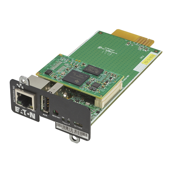
Front panel connectors and LED indicators 6 Information 6.1 Front panel connectors and LED indicators Name Description Network connector Ethernet port Network speed LED Flashing green sequences: • 1 flash — Port operating at 10Mbps • 2 flashes — Port operating at 100Mbps •... -
Page 92: Default Settings Parameters
Default settings parameters Warning LED Solid red — Network Module is in error state. Boot LEDs Solid green and flashing red — Network Module is starting boot sequence. Settings/UPS data Configuration port. connector Access to Network Module’s web interface through RNDIS (Emulated Network port). Access to the Network Module console through Serial (Emulated Serial port). -
Page 93: Network
Default settings parameters Minimum length — enabled (8) Minimum length — enable (6-32)/disable Password Minimum upper case — enabled (1) Minimum upper case — enable (0-32)/disable strength Minimum lower case — enabled (1) Minimum lower case — enable (0-32)/disable Minimum digit — enabled (1) Minimum digit — enable (0-32)/disable Special character — enabled (1) Special character — enable (0-32)/disable Password expires after — disabled Password expires after — disable/enable Account (1-99999) Main administrator password never expiration expires — disabled Main administrator password never expires — disable/enable Block account when invalid password is entered after — Block account when invalid password is disabled entered after — disable/enable (1-99) Main administrator account never Main administrator account never blocks —... -
Page 94: Snmp
Default settings parameters SNMP Default setting Possible parameters Enable — disabled Enable — disable/enable SNMP Port — 161 Port — x-xxx SNMP V1 — disabled SNMP V1 — disable/enable • Community #1 — public • Community #1 — 128 characters maximum Status — Inactive Status — Inactive/Active Access — Read only Access — Read only • Community #2 — private • Community #2 — 128 characters maximum Status — Inactive Status — Inactive/Active Access — Read/Write Access — Read/Write SNMP V3 — enabled SNMP V3 — disable/enable • User #1 — readonly •... -
Page 95: Email
Default settings parameters Email Default setting Possible parameters No email 5 configurations maximum Email sending Active — Active/Inactive configuration Configuration name — 128 characters maximum Email address — 128 characters maximum • Delegate email to Active — No/Yes Email addresses – List of emails Keep primary email address in copy – disable/enable Starting – Date and time Ending – Date and time • Notify on events Active — No/Yes On card events – Subscribe/Attach logs (Critical/Warning/Info) On devices events – Subscribe/Attach logs... -
Page 96: My Preferences
Default settings parameters My preferences Default setting Possible parameters Edit user: Edit user: Profile • Full name — Administrator • Full name — 128 characters maximum • Email — blank • Email — 128 characters maximum • Phone — blank • Phone — 64 characters maximum • Organization — blank • Organization — 128 characters maximum °C (Celsius) °C (Celsius)/°F (Fahrenheit) Temperature MM-DD-YYYY... - Page 97 Default settings parameters Dry contacts Enabled — No Enabled — No/Yes Alarm severity – Warning Alarm severity – Info/Warning/Critical Information – 97...
-
Page 98: Specifications/Technical Characteristics
Specifications/Technical characteristics 6.3 Specifications/Technical characteristics Physical characteristics Dimensions (wxdxh) 132 x 66 x 42 mm | 5.2 x 2.6 x 1.65 in Weight 70 g | 0.15 lb RoHS 100% compatible Storage Storage temperature -25°C to 70°C (14°F to 158°F) Ambient conditions Operating temperature 0°C to 70°C (32°F to 158°F) -
Page 99: List Of Events Codes
List of events codes Settings/UPS data USB RNDIS Apipa compatible | IP address: 169.254.0.1 | Subnet mask: connector 255.255.0.0 *xUPS MIB | Standard IETF UPS MIB (RFC 1628) 6.4 List of events codes To get access to the Alarm log codes or the System log codes for email subscription, see the Alarm log codes and System log codes sections. 6.5 Alarm log codes ... - Page 100 Alarm log codes Critical Rectifier short circuit Rectifier OK Reduce output load Critical DCDC converter failure DCDC converter OK Service required Critical Battery charger fault Battery charger OK Service required Critical Battery fuse fault Battery fuse OK Service required Critical Battery low Battery OK Critical...
-
Page 101: Warning
Alarm log codes Critical Inverter thermal No power overload Reduce output overload load Critical Inverter voltage too low Inverter voltage OK Service required Critical Inverter voltage too high Inverter voltage OK Service required 6.5.2 Warning Code Severity Active message Non active message Advice Warning On battery... -
Page 102: Info
Alarm log codes Warning Battery low voltage Battery OK Warning Battery voltage too high Battery voltage OK Warning Load not powered Load powered Warning Power overload No power overload Reduce output load Warning Overload alarm No overload Reduce output load 1032 Warning Protection: immediate... -
Page 103: With Settable Severity
Alarm log codes 1016 Info Protection: sequential Protection: sequential shutdown scheduled shutdown canceled 1017 Info Protection: sequential Protection: sequential shutdown in progress shutdown completed 1100 Info Schedule: shutdown Schedule: shutdown date reached initiated 1101 Info Schedule: restart date Schedule: restart reached initiated Info... -
Page 104: System Log Codes
System log codes 6.6 System log codes To retrieve System logs, navigate to Card>>>System logs section and press the Download System logs button. 6.6.1 Alert Code Severity Log message File 0801000 Alert User account - admin password reset to default logAccount.csv 6.6.2 Critical Code Severity Log message File 0E00400 Critical The [selfsign/PKI] signed certificate of the <service> logSystem.csv server is not valid 6.6.3 Error... -
Page 105: Notice
System log codes 6.6.5 Notice Code Severity Log message File 0300D00 Notice User action - sanitization launched logSystem.csv 0A00500 Notice Network module sanitized logUpdate.csv 0A00900 Notice Network module bootloader upgrade success <f/w: logUpdate.csv xx.yy.zzzz> 0A00B00 Notice Network module bootloader upgrade started <f/w: logUpdate.csv xx.yy.zzzz>... -
Page 106: Info
System log codes 6.6.6 Info Code Severity Log message File 0A00100 Info Network module upgrade success <f/w: xx.yy.zzzz> logUpdate.csv 0A00300 Info Network module upgrade started logUpdate.csv 0A00600 Info Network module file system integrity OK <f/w: logUpdate.csv xx.yy.zzzz> 0B00300 Info Time with NTP synchronized logSystem.csv 0B00600 Info... -
Page 107: Snmp Trap Oid
SNMP trap oid 6.7 SNMP trap oid 6.7.1 Eaton XupsMIB trap oid and message: Trap oid: Message .1.3.6.1.4.1.534.1.11.4.1.0.x .1.3.6.1.4.1.534.1.11.4.1.0.3 Battery discharging .1.3.6.1.4.1.534.1.11.4.1.0.4 Battery low .1.3.6.1.4.1.534.1.11.4.1.0.5 No more on battery .1.3.6.1.4.1.534.1.11.4.1.0.6 Battery OK .1.3.6.1.4.1.534.1.11.4.1.0.7 Power overload .1.3.6.1.4.1.534.1.11.4.1.0.8 Internal failure .1.3.6.1.4.1.534.1.11.4.1.0.10 Inverter internal failure .1.3.6.1.4.1.534.1.11.4.1.0.11 Bypass mode .1.3.6.1.4.1.534.1.11.4.1.0.12... -
Page 108: Cli
CLI .1.3.6.1.4.1.534.1.11.4.1.0.43 Sensor humidity is below/above critical threshold .1.3.6.1.4.1.534.1.11.4.1.0.48 Maintenance bypass 6.8 CLI CLI can be accessed through SSH. It is intended mainly for automated configuration of the network and time settings of the network card. It can also be used for troubleshooting and remote reboot/reset of the network interface in case the web user interface is not accessible. -
Page 109: Examples Of Usage
-4, --ipv4 <mode> Mode values: manual <network> <mask> <gateway> set custom Network address, Netmask and Gateway dhcp automatically set Network Address, Netmask and Gateway Examples of usage • Display Link status and MAC address netconf -L • Set Auto negotiation to Link netconf -L auto • Set custom hostname\n \ netconf -d hostname ups-00-00-00-00-00-00 •... -
Page 110: Examples Of Usage
6.9.1 Availability of Source Code The source code of open source components that are made available by their licensors may be obtained upon written express request by contacting network-m2-opensource@Eaton.com. Eaton reserves the right to charge minimal administrative costs, in compliance with the terms of the underlying open source licenses, when the situation requires. -
Page 111: Notice For Our Proprietary (I.e. Non-Open Source) Elements
Legal Information pages, available from the HTML user interface of the present product. 6.9.3 Notice for our proprietary (i.e. non-Open source) elements Copyright © 2017 Eaton. This firmware is confidential and licensed under Eaton Proprietary License (EPL or EULA). This firmware is not authorized to be used, duplicated, or disclosed to anyone without the prior written permission of Eaton. -
Page 112: Acronyms And Abbreviations
Acronyms and abbreviations 6.10 Acronyms and abbreviations AC: Alternating current. AVR: Automatic Voltage Regulation provides stable voltage to keep equipment running in the optimal range. CA: Certificate Authority CLI: Command Line Interface. Aim is to interact with the Network Module by using commands in the form of successive lines of text (command lines). CSR: Certificate Signing Request DC: Direct current. - Page 113 Acronyms and abbreviations SSH: Secure Shell is a cryptographic network protocol for operating network services securely over an unsecured network. TLS: Transport Layer Security (TLS) is cryptographic protocol that provide communications security over a computer network. TFTP: Trivial File Transfer Protocol (TFTP) is a simple lockstep File Transfer Protocol which allows a client to get a file from or put a file onto a remote host. UPS: An uninterruptible power supply is an electrical apparatus that provides emergency power to a load when the input power source or mains power fails. A UPS is typically used to protect hardware such as computers, data centers, telecommunication equipment or other electrical equipment where an unexpected power disruption could cause injuries, fatalities, serious business disruption or data loss.
- Page 114 Acronyms and abbreviations Information – 114...
-
Page 115: Troubleshooting
EMP detection fails at discovery stage 7 Troubleshooting 7.1 EMP detection fails at discovery stage 7.1.1 Symptoms In the Network Module, in Card>>>Sensors, EMPs are missing in the Sensor commissioning table. 1. The EMPs orange RJ45 LEDs are not blinking. 2. The EMPs green RJ45 LED (FROM DEVICE) is not ON. 7.1.2 Possible cause 1. -
Page 116: Possible Cause
IPP is not able to communicate with the Network module 7.3.2 Possible cause The IPP certificate is not yet valid for the Network Module. Certificates of IPP and the Network Module are not matching so that authentication and encryption of connections between the Network Module and the shutdown agents is not working. -
Page 117: Password Change In My Preferences Is Not Working
During the selected timeframe, new agent connections to the Network Module are automatically trusted and accepted. STEP 4: Action on the agent (IPP) while the time to accepts new agents is running on the Network Module Remove the Network module certificate file(s) *.0 that is (are) located in the folder Eaton \IntelligentPowerProtector\configs\tls. 7.4 Password change in My preferences is not working 7.4.1 Symptoms The password change shows "Invalid credentials" when I try to change my password in My preferences menu.
Need help?
Do you have a question about the Network-M2 and is the answer not in the manual?
Questions and answers