
Summary of Contents for Advanced Energy MDX II
- Page 1 MDX II ™ 5700262-R Advanced Energy Industries, Inc. 1625 Sharp Point Drive Fort Collins, CO 80525 USA 800.446.9167 technical.support@aei.com April 2002...
- Page 3 User Manual MDX II ™ 5700262-R...
- Page 4 All personnel who work with or who are exposed to this equipment must take precautions to protect themselves against serious or possibly fatal bodily injury. Advanced Energy Industries, Inc., (AE) provides information on its products and associated hazards, but it assumes no responsibility for the after-sale operation of the equipment or the safety practices of the owner or user.
-
Page 5: Table Of Contents
MDXII Power Supplies Table of Contents Chapter 1. Introduction ............1 Read This Section!. - Page 6 ® Advanced Energy Physical Specifications ..............1 Electrical Specifications .
- Page 7 MDXII Power Supplies Clicks ............... . . 17 Serial Port Timeout Value .
- Page 8 ® Advanced Energy Specifying Serial Port Timeout Value ..........15 Using the HALO Feature .
- Page 9 MDXII Power Supplies User Port Output Signals ............13 AE Customer Support .
- Page 10 ® Advanced Energy Start-up Procedure ..............17 Master/Slave Operation .
- Page 11 MDXII Power Supplies List of Figures Figure 2-1. MDXII unit functional block diagram ........5 Figure 2-2.
- Page 12 ® Advanced Energy Figure A-2. Passive panel of an MDXII 18P unit ........7 Figure A-3.
- Page 13 MDXII Power Supplies List of Tables Table 1-1. Electromagnetic Compatibility (EMC) ........4 Table 1-2.
- Page 14 ® Advanced Energy Table B-2. Output Power ............1 Table B-3.
-
Page 15: Chapter 1. Introduction
MDXII Power Supplies Chapter Chapter Introduction READ THIS SECTION! We know that some of you want to start the MDXII magnetron drive now and that you don't feel you have the time to read the entire manual. Below is a list of manual sub-sections you must read before getting started. - Page 16 ® Advanced Energy We include this symbol in Danger, Warning, and Caution boxes to identify specific levels of hazard seriousness. DANGER: This box identifies immediate hazards which will result in severe personal injury or death. WARNING: This box identifies hazards or unsafe practices which could result in severe personal injury or death.
- Page 17 MDXII Power Supplies • Earth ground • Warning (refer to manual) • CE label • Non-ionizing radiation 5700262-R Introduction...
-
Page 18: Safety
® Advanced Energy SAFETY Do not attempt to install or operate this equipment if you have not first acquired proper training. • Ensure that this unit is properly grounded. • Ensure that all cables are properly connected. • Verify that input line voltage and current capacity are within specifications before turning on the power supplies. -
Page 19: Standards
MDXII Power Supplies Standards If your MDXII unit bears the “CE” mark: • The device has been tested for and complies with the following Safety and EMC standard(s): – VDE 0160 – EN 50082-2 – EN 55011 (Class A, Group 2)(CISPR 11) Your MDXII unit must be installed and used only in compliance with the standards listed in addition to VDE 0113, EN 60204 (IEC 204), and applicable requirements. - Page 20 ® Advanced Energy Introduction 5700262-R...
-
Page 21: Chapter 2. Product Overview
Chapter Product Overview GENERAL DESCRIPTION ® The Advanced Energy MDXII dc magnetron drive is a sophisticated and intelligent dc power supply designed exclusively for use in vacuum environments. The MDXII drive provides the ultimate advantages in dc power by: • Setting a new standard for compactness, accuracy, reliability, and flexibility •... -
Page 22: Panels
® Advanced Energy Panels The following panels may be present in your MDXII unit’s configuration: • Active front panel - this panel is an integrated part of the MDXII unit. The panel has a display, switches, soft keys, and a MODIFY knob that you use to control the operation of your MDXII unit. -
Page 23: Interfaces
MDXII Power Supplies Interfaces The MDXII unit provides a broad array of operational features and settings, most of which you can control and/or monitor using one of three interfaces: • A control panel (active front panel or active remote panel) The control panel is an active interface that gives you direct access to all operating parameters and control functions through the use of switches, softkeys, and the MODIFY knob. -
Page 24: Unit Control Hierarchy
® Advanced Energy Unit Control Hierarchy The MDXII unit gives default operation control to one of the above three interfaces based on the following hierarchy: 1. Control panel (if your MDXII unit has an active front panel or an active remote panel) 2. -
Page 25: Output Regulation
MDXII Power Supplies Output Regulation You can use the MDXII unit as a power, current, or voltage source, depending on the method of output regulation you select using the REGULATION switch on the control panel. Because setpoint levels are stored in nonvolatile memory, you can use them to recover from input power interruptions and to ensure repeatability from run to run. -
Page 26: Figure 2-2. Switching Theory
® Advanced Energy Input Inverter Output Section Section Section Ripple Choke Filter Relays Output Output Rectifier DC Output Transformer Relays Bridges Input Input Rectifier Switching Bridges Transistors 1248 Figure 2-2. Switching theory Figure 2-3 on page 2-6 is a detail of the previous figure, showing the current flow through switching transistors. -
Page 27: Software Highlights
MDXII Power Supplies Output Measurement The output measurement section measures current and voltage and calculates power. These signals are typically scaled to 0 to 10 Vdc and sent to the logic, control, and remote interfaces. Logic Control The microprocessor in the logic control section uses operator-supplied parameters and setpoints to control the output. -
Page 28: Halo
® Advanced Energy HALO HALO (high accuracy at low output) is available on MDXII stand-alone units that do not feature the VHALO software option (for more about software options, see “Understanding the Optional Software Features” on page 2-19). HALO increases the accuracy of the User port scaling when the unit is operating in low output ranges. -
Page 29: Timers
MDXII Power Supplies Timers The software lets you program: • Ramp time - the amount of time the MDXII unit takes to reach a programmed output setpoint • Run time - the amount of time the MDXII unit is specified to run. When this time is reached, output shuts off. -
Page 30: Table 2-1. Hex-Conversion Table
® Advanced Energy 7. On the following pages find the table that corresponds with your unit’s software version. (To identify your unit’s software version, see “Identifying Software Versions” on page 2-9.) Write your conversion on the last row of the table (see example Table 2-3 on page 2-12). -
Page 31: Table 2-2. Example Software Options Table
MDXII Power Supplies Table 2-1. Hex-Conversion Table Binary 1101 1110 1111 Table 2-2. Example Software Options Table Option Definition Opt1 = Fast Run/Ramp Opt2 = ArcCheck Opt3 = 460 to 480 V Line Input Opt4 = 5 V Analog Input in User Port Opt 5 = unassigned Opt 6 = Varc Shutdown Enable Opt 7 = VHALO... -
Page 32: Table 2-3. Software Options 7001020 - Expanded Profibus Command Set/Fast User Port
® Advanced Energy Table 2-3. Software Options 7001020 - Expanded Profibus Command Set/Fast User Port Option Definition Opt1 = Fast Run/Ramp Opt2 = Arc-Check Opt3 = 460 to 480 V Line Input Opt4 = 5 V Analog Input in User Port... -
Page 33: Table 2-4. Software Options 7004000 - Standard Mdxii Unit
MDXII Power Supplies Table 2-4. Software Options 7004000 - Standard MDXII Unit Option Definition Opt1 = Fast Run/Ramp Opt2 = A.00 - 7004000B: Arc-Check 7004000D.00 -: ASCII serial port (Arc-Check always enabled) Opt3 = 460 to 480 V Line Input Opt4 = 5 V Analog Input in User Port Opt 5 = Unit Ready for Turn On Opt 6 = Varc Shutdown Enable... -
Page 34: Table 2-5. Software Options 7004002 - Mdxii Master/Slave Unit
® Advanced Energy Table 2-5. Software Options 7004002 - MDXII Master/Slave Unit Option Definition Opt1 = Fast Run/Ramp Opt2 = Arc-Check Opt3 = 460 to 480 V Line input Opt4 = 5 V Analog Input in User port Opt 5 = Unit Ready for Turn On... -
Page 35: Table 2-6. Software Options 7004025 - Mdxii Profibus/Fast User
MDXII Power Supplies Table 2-6. Software Options 7004025 - MDXII Profibus/Fast User Option Definition Opt1 = Fast Run/Ramp Opt2 = Arc-Check Opt3 = 460 to 480 V Line Input Opt4 = 5 V Analog Input in User Port Opt 5 = unassigned Opt 6 = Varc Shutdown Enable Opt 7 = Voltage HALO Opt8 = 18P Mode of Operation... -
Page 36: Table 2-7. Software Options 7004027 - Mdxii Auto Contactor
® Advanced Energy Table 2-7. Software Options 7004027 - MDXII Auto Contactor Option Definition Opt1 = Fast Run/Ramp Opt2 = Arc-Check Opt3 = 460 to 480 V Line Input Opt4 = 5 V Analog Input in User Port Opt 5 = Unit Ready for Turn On... -
Page 37: Table 2-8. Software Options 7002218 - Standard Mdxii (Universal Logic Card)
MDXII Power Supplies Table 2-8. Software Options 7002218 - Standard MDXII (Universal Logic Card) Option Definition Opt1 = Fast Run/Ramp Opt2 = Arc-Check Opt3 = 460 to 480 V Line Input Opt4 = 5 V Analog Input in User Port Opt 5 = Unit Ready for Turn On Opt 6 = Varc Shutdown Enable Opt 7 = Voltage HALO... -
Page 38: Table 2-9. Software Options 7002216 - Mdxii Ce Fast User Port (Universal Logic Card)
® Advanced Energy Table 2-9. Software Options 7002216 - MDXII CE Fast User Port (Universal Logic Card) Option Definition Opt1 = Fast Run/Ramp Opt2 = Arc-Check Opt3 = 460 to 480 V Line Input Opt4 = 5 V Analog Input in User Port... -
Page 39: Understanding The Optional Software Features
MDXII Power Supplies Understanding the Optional Software Features The electronically-stored optional software features configure your MDXII unit to specific parameters automatically each time you power on your unit. Software options are selected at the time a unit is ordered. Your unit has only those options ordered, not necessarily all those listed below. - Page 40 ® Advanced Energy 18kW Power If this option has been activated, the MDXII unit can deliver 18 kW if pin 8 (CLEAR.D) of the User port is active. The MDXII power supply can operate at 18 kW for a maximum time on of 10 s and a maximum duty cycle of 80%.
- Page 41 MDXII Power Supplies Full Power Maximum Peak Output Voltage Maximum Limit Average Tap Select Tap Select Output Voltage Limits Voltage Limits Voltage Enabled Not Enabled 1000 V 1050 V 1600 V 1250 V 1313 V 1600 V User Port ON/OFF If this option has not been activated, the MDXII unit operates Priority with the User port on/off signals taking priority in any control...
- Page 42 ® Advanced Energy 25 V Voltage Arc If this option has been activated at the same time as Varc Shutdown Enable, you can adjust the Varc trip level(s) from 25 to 400 V, rather than 50 to 400 V. For more information about trip levels, see “Arc Trip Levels”...
-
Page 43: Custom Options
MDXII Power Supplies CUSTOM OPTIONS This section describes the two custom software options in more depth and describes two orderable custom hardware sets. Custom Software 2 SETPOINT, 4 TARGET SOFTWARE Adds Target/Setpoint Functionality This 2 Setpoint/4 Target software version lets you use a single supply in two processes while maintaining a setpoint and two target counters for each process. -
Page 44: Auto-Contactor Software
® Advanced Energy AUTO-CONTACTOR SOFTWARE This auto-contactor software version includes a software change that allows the contactor to close automatically when the supply has no active faults. If a fault occurs, the contactor opens normally and closes again automatically once the fault is cleared. -
Page 45: Chapter 3. Specifications
MDXII Power Supplies Chapter Chapter Specifications PHYSICAL SPECIFICATIONS Table 3-1. MDXII 15k and 30K Physical Specifications Recommended Input Cable MDXII 15k model: 5-wire AWG 6, 600 V (not supplied with unit) MDXII 30k model: 5-wire AWG 6, 600 V Methods of Control Full or restricted access, local or remote control, programmed or manual operation Output Connector... -
Page 46: Electrical Specifications
® Advanced Energy ELECTRICAL SPECIFICATIONS Table 3-2. MDXII 15k and 30k Electrical Specifications Input Voltages (internally Either 380/400/415 V ac ± 10% or ∆ selected) 440/460/480 V ac ±10%, 50/60 Hz, three-phase Y or maximum ground leakage current less than 3.5mA. -
Page 47: Environmental Specifications
MDXII Power Supplies ENVIRONMENTAL SPECIFICATIONS Table 3-4. Climatic Specifications Temperature Relative Humidity Air Pressure Class 3K3 Class 3K2 Class 3K3 Operating (Note 1) (Note 2) 0°C to +40°C 20% to 80% 80 kPa to 106 kPa +32°F to +104°F +6 g/m to 23.5 g/m 800 mbar to 1060 mbar (approximately 2000 m... - Page 48 ® Advanced Energy Specifications 5700262-R...
-
Page 49: Chapter 4. Installation
Unpack and inspect your MDXII power supply carefully. Check for obvious physical damage. If no damage is apparent, proceed to make the connections. If you do see signs of shipping damage, contact Advanced Energy Industries, Inc. and the carrier immediately. Save the shipping container for submitting necessary claims to the carrier. -
Page 50: Spacing Requirements
® Advanced Energy Spacing Requirements • The clearance between either side of the MDXII unit and the enclosure must be 76 mm (3 in). • The clearance between the top of the MDXII unit and the top of the enclosure must be 25 mm (1 in). -
Page 51: Figure 4-2. Rear Clearance Requirements For Mdxii Units Stacked In A Cabinet
MDXII Power Supplies Figure 4-2. Rear clearance requirements for MDXII units stacked in a cabinet 5700262-R Installation... -
Page 52: Cooling Requirements
® Advanced Energy Cooling Requirements The MDXII unit is an air-cooled power supply, so ensuring that adequate ventilation is provided is important. For the MDXII unit to be sufficiently cooled, the cabinet must be set up to: • Bring in coolant air of the correct temperature (35°C maximum) •... -
Page 53: Cabinet Design
MDXII Power Supplies Cabinet Design You must install the MDXII unit in an interlock cabinet in accordance with IEC, EN, and national or local requirements. The following is a synopsis of the principles to follow when designing a cabinet containing a stack of MDXII power supplies. -
Page 54: Figure 4-4. Cooling Pattern For Several Units Enclosed In A Cabinet
® Advanced Energy Input air, Input air, front front Exhaust air directly from Exhaust air directly from the rear of cabinet the rear of cabinet 1251 1251 Figure 4-4. Cooling pattern for several units enclosed in a cabinet Installation 5700262-R... -
Page 55: Rear Panel Connections
MDXII Power Supplies REAR PANEL CONNECTIONS DANGER: RISK OF DEATH OR BODILY INJURY: disconnect all sources of input power and wait a few minutes before working on this unit or anything connected to it. Internal components may remain live for 1 min after the MDXII unit has been disconnected. Grounding On the MDX 15k, a potential equalization ground stud is located in the upper right-hand quadrant of the rear panel. - Page 56 ® Advanced Energy An “N” on the label plate on the rear of the unit indicates that the neutral is internally connected. You must connect your neutral wire to this N terminal. If the label plate shows no “N,” no neutral connection is required. A specific phase rotation is not required on any model.
-
Page 57: Figure 4-5. Connecting The Input
MDXII Power Supplies 9. Connect the shield to the earth ground stud on the back of the unit. Figure 4-5. Connecting the Input 5700262-R Installation... -
Page 58: Output Power Connection
® Advanced Energy Output Power Connection The standard output connector is a molded, pluggable connector with cable compression screws. Either type MV-90 cable or discrete high-voltage wires are required to make the output connection. The cables for the output connection are not included with the MDXII power supply. Use connecting wire that is consistent with your application and applicable requirements. -
Page 59: Negative Output
MDXII Power Supplies Two styles of output cabling satisfy both of the above optimal conditions: “triax” cabling and “twinax” cabling (see Figure 4-6 on page 4-11). Figure 4-6. Two styles of cables for optimal output connection Triax cable is much like coax cable, except that triax contains an additional shield that surrounds an inner shield and center conductor. -
Page 60: Figure 4-7. Connector Wired For Negative Output
® Advanced Energy to chamber anode unterminated to chamber wall outer shield Figure 4-7. Connector wired for negative output 4-12 Installation 5700262-R... -
Page 61: Positive Output
MDXII Power Supplies POSITIVE OUTPUT For special applications that require a positive output voltage (positive with respect to ground), follow these steps: 1. Connect the unit’s positive terminal on the output connector to the load. 2. Connect the negative terminal on the unit’s output connector to the load’s common or ground. -
Page 62: Figure 4-8. Connector Wired For Positive Output
® Advanced Energy to negative terminal of load to positive unterminated terminal of load outer shield Figure 4-8. Connector wired for positive output 4-14 Installation 5700262-R... -
Page 63: Floating Output
MDXII Power Supplies FLOATING OUTPUT You can configure the MDXII unit’s output such that neither the negative output terminal or the positive output terminal has a direct connection to ground (floating output). To connect for floating output, follow these steps: 1. -
Page 64: Other Connections
® Advanced Energy OTHER CONNECTIONS Connections for an active remote panel, User port, and serial port are explained in other chapters. • See page 6-1 to connect an active remote panel. • See page 9-1 to connect the User port. -
Page 65: Chapter 5. Operation Overview
MDXII Power Supplies Chapter Chapter Operation Overview This chapter provides an overview of the MDXII unit’s operational functions and settings to give you an understanding of their purpose and use before you perform the operations. Information on using these functions and settings is described in other parts of this manual, as follows: •... -
Page 66: Current
® Advanced Energy Current Select current regulation from the control panel by pressing the CURRENT switch. Through the serial port interface, use Command 3 to select current regulation. Through the User port interface, pin 5 (I REG.D) must be low and pin 6 (PREG.D) must be high. -
Page 67: Output Setpoint Level
MDXII Power Supplies You can program up to five different ramp/run combinations (steps) to run consecutively, which forms one recipe (see “Steps and Recipes” on page 5-4). Setting a zero run time for any step causes that step to be the last step. When the MDXII unit reaches a step specifying a zero run time, it ramps to the setpoint and runs continuously. -
Page 68: Allowable Setpoint Deviation
® Advanced Energy ALLOWABLE SETPOINT DEVIATION Allowable setpoint deviation lets you customize the MDXII unit's out-of-setpoint function. If you specify a non-zero value for the out-of-setpoint timer, you can set an allowable deviation of 1 to 99% for that setpoint; entering an out-of-setpoint value of zero disables this feature. -
Page 69: Arc Controls
® User port pins 1 and 20 tell an external device (such as the Advanced Energy cathode- switching box) which of eight targets the MDXII unit has been set to decrement. They reflect selections made from the control panel, host computer, or User port. -
Page 70: Arc Delay And Density
® Advanced Energy When the arc count limit is reached, the control panel displays either a flashing “Varc” or “Iarc” or the User port (if set at the factory) alerts you (see page 9-1). You cannot monitor arc count through the serial port. -
Page 71: Tap Settings
MDXII Power Supplies have some of the characteristics of arcs, which is confusing to some circuitry. Arc-Check was developed to deal with these arc-like process phenomena, eliminating short-inducing flakes in applications where keeping the chamber extremely clean is impractical. You can program this optional feature from the control panel or through the serial port. Arc-Check waits the amount of time you specify (50 ms to 5 s) and then attempts to extinguish the “arc”... -
Page 72: Selecting The Correct Tap
® Advanced Energy Table 5-1. Maximum Tap Setting Voltages and Currents (Continued) Max. Maximum Output Number Output Current Voltage MDXII 15k MDXII 30k tap 4 800 V 24.00 A 48.00 A tap 5 1000 V 18.75 A 37.50 A tap 6 1250 V 15.00 A... - Page 73 MDXII Power Supplies target when new 780 V target at end of target life (EOTL) 600 V Power Current -------------------- To calculate the operating currents, use Voltage 13.8kW ------------------ 17.7A current for new target 780V current at EOTL 13.8kW ------------------ 600V Now you have the voltage range and current range for the target over its useful life.
- Page 74 ® Advanced Energy target when new 780 V target at end of target life (EOTL) 550 V Power Current -------------------- To calculate the operating currents, use Voltage 13.8kW ------------------ 17.7A current for new target 780V 13.8kW ------------------ 25.1A current at EOTL 550V Now you have the voltage range and current range for the target over its useful life.
- Page 75 MDXII Power Supplies 1254 Shown are the voltage and current values plotted for the Example 1 target both when it is new and when it is near the end of its useful life (EOTL). The impedances at both target stages fall within the boundaries of tap 4. Figure 5-1.
-
Page 76: Figure 5-2. Impedances Plotted For The Example 1 Target
® Advanced Energy 1255 Shown are the impedances plotted for the Example 1 target both when it is new and when it is near the end of its useful life (EOTL). Figure 5-2. Impedances plotted for the example 1 target... -
Page 77: Figure 5-3. Voltage And Current Values For The Example 2 Target Out Of Range
MDXII Power Supplies 1256 Shown are the voltage and current values plotted for the Example 2 target both when it is new and when it is near the end of its useful life (EOTL). The EOTL current is out of the range of tap 4. Figure 5-3. -
Page 78: Figure 5-4. Impedances Plotted For The Example 2 Target
® Advanced Energy 1257 Shown are the impedances plotted for the Example 2 target both when it is new and when it is near the end of its useful life (EOTL). Figure 5-4. Impedances plotted for the example 2 target... - Page 79 MDXII Power Supplies 1258 Shown are the voltage and current values plotted for the Example 2 target both when it is new and when it is near the end of its useful life (EOTL). In this example, we switched to an MDXII unit capable of producing 30 kW, so both target stages fall within the boundaries of tap 4.
-
Page 80: Power Supply Enhancements
® Advanced Energy POWER SUPPLY ENHANCEMENTS Several configuration choices help increase the flexibility of the MDXII power supply. Lock The lock function provides security for your system. When the control panel is locked, only people who know the unlock code can get access to the menu and make changes. When locked, you cannot turn on the MDXII unit from the control panel, and all the settings are protected from unauthorized changes. -
Page 81: Clicks
MDXII Power Supplies You can change the program source and even set a different source for each of the three operating modes (host, local, analog). Thus it is possible to: • Set the program source to internal from the control panel or through the serial port interface, which gives control of the regulation mode, setpoints, and ramp/run sequences to the control panel or serial port) and •... -
Page 82: Transductor Calibration
® Advanced Energy Transductor Calibration The purpose of the transductor calibration function is to calibrate the transductor by zeroing the “Amps” reading. You can program this function from the control panel and through the serial port. FEATURES/OPTIONS ASCII If your MDXII unit has the ASCII host communications option enabled (through an active panel or a serial port), serial communications will use ASCII characters rather than binary values. -
Page 83: Halo
MDXII Power Supplies ASCII: Request from the host: ‘0’ ‘8’ ‘C’ ‘6’ ‘C’ ‘5’ Header Command Checksum (Optional) Acknowledge and data from the MDXII: ‘0’ ‘B’ ‘C’ ‘6’ ‘4’ ‘1’ ‘3’ ‘0’ ‘3’ ‘5’ ‘8’ ‘9’ Header Command Data - ‘A’ Data - ‘0’... -
Page 84: Vhalo
® Advanced Energy VHALO When the VHALO software option is active on your unit, you can invoke VHALO only through the User port when the MDXII unit is in tap 1 and User port pin 33 (HALO.D) is asserted. When these conditions are true, User port pin 23 (VOUT.A), pin 27 (LEVEL IN.A), and pin 31 (LEVEL OUT.A) are scaled 0 to 10 V, which represents 0 to 400 V. -
Page 85: Service Functions
MDXII Power Supplies SERVICE FUNCTIONS System Statistics The MDXII unit keeps track of some numbers that are important to AE Customer Support. These numbers identify bus faults, which are momentary power faults that can be used to help verify line-power problems. You can obtain the following system statistics from the control panel or through the serial port. -
Page 86: References To Operation Functions
® Advanced Energy REFERENCES TO OPERATION FUNCTIONS Table 5-1 on page 5-22 lists all the MDXII unit’s operation functions, including a reference back to a description of each function in this chapter and where (in other chapters) you can find out how to use each function from the applicable interface(s). - Page 87 MDXII Power Supplies Table 5-1. Operation Reference Table (Continued) What It Operation How To Use Serial Port User Control Commands Port Panel Pins AE Bus Profibus Steps and page 5-4 page 6-6 Recipes to page page 5-8 Command 20, Command 25, HALO page 5-19 page 7-28...
- Page 88 ® Advanced Energy Table 5-1. Operation Reference Table (Continued) What It Operation How To Use Serial Port User Control Commands Port Panel Pins AE Bus Profibus Arc Control Arc Count page 5-5 page 6-10 pin 21, page 9-12 Delay page 5-6...
- Page 89 MDXII Power Supplies Table 5-1. Operation Reference Table (Continued) What It Operation How To Use Serial Port User Control Commands Port Panel Pins AE Bus Profibus Features and Options ASCII page 5-18 page 6-16 Command 72, page 7-37 HALO page 5-19 page 6-15 pin 33, Command 32, page 7-35 to...
- Page 90 ® Advanced Energy Table 5-1. Operation Reference Table (Continued) What It Operation How To Use Serial Port User Control Commands Port Panel Pins AE Bus Profibus System Statistics Times input page 5-21 page 6-17 Command 201, page 7-55 power turned on...
-
Page 91: First-Time Operation
MDXII Power Supplies FIRST-TIME OPERATION This procedure assumes that a control panel has operational control (local control mode). 1. Ensure that the necessary external inputs are supplied (refer to signal descriptions beginning on page 9-7) or that the “cheater plug” is installed on the User port connector on the rear of the MDXII unit (see Figure 9-6 on page 9-5). - Page 92 ® Advanced Energy 5-28 Operation Overview 5700262-R...
-
Page 93: Chapter 6. Panel Connection, Controls And Indicators
To properly initialize the active remote panel, you must connect when the MDXII unit is ® off (no live power). This connector was designed for connecting an Advanced Energy ® active remote panel only. The communications format between Advanced Energy display panels and the MDXII unit is different than the serial port communications format. -
Page 94: Control Panel Interface
® Advanced Energy CAUTION: If the User port won't be used, you must leave the cheater plug attached to the MDXII unit. CONTROL PANEL INTERFACE Your MDXII unit may have either an active front panel, which is an integrated part of the unit, or an active remote panel, which is connected to the DISPLAY port on the rear panel of the unit. -
Page 95: Regulation Switches
MDXII Power Supplies Regulation Switches Use these switches to select the method of output regulation when the control panel has control. POWER Specifies that the method of output regulation is power VOLTAGE Specifies that the method of output regulation is voltage CURRENT Specifies that the method of output regulation is current Two-Line Display... -
Page 96: Figure 6-2. Control Panel First-Level Menu Functions
® Advanced Energy Use the MODIFY knob and the five unlabeled soft keys that are directly below the display to select parameters and modify values. To have full access to the menu, the MDXII unit must be in local control mode (the LOCAL LED will be lit). -
Page 97: Figure 6-3. Control Panel Menu Tree
MDXII Power Supplies CURRENT LIMITS POWER RAMP n TIMER RAMP/RUN NUMBER OF STEPS TIMERS SETPOINT n = OUT-OF-SETPOINT RUN n TIMER OUT-OF-SETPOINT TIMER ACTIVE TARGET TARGET LIFE REMAINING LIFE DELAY VARCS DENSITY IARCS ARC CHECK ACTIVE? ARC CHECK ARC CHECK HOLD-OFF VARCS COUNT IARCS... -
Page 98: Using Limits Functions
® Advanced Energy The next several pages contain step-by-step instructions on how to access and perform operational functions from the MDXII control panel menu. These instructions are organized by the first-level menu functions illustrated in Figure 6-2 on page 6-4. -
Page 99: Programming Output Setpoint Level
MDXII Power Supplies 8. Either set the RUN 1 time or press the ENTER soft key (see “Run Timer” on page 5-2). Pressing the ENTER soft key at the final timer value automatically returns you to the output display screen. Note: Press the MODIFY knob at any time to return to the output display screen;... -
Page 100: Setting Run Time
® Advanced Energy SETTING RUN TIME See “Run Timer” on page 5-2 for a description of this function. ⇒ ⇒ ⇒ TIMERS RAMP/RUN Number of steps run n timer 1. At the top-level menu, press the TIMERS soft key. 2. Press the RAMP/RUN soft key. -
Page 101: Setting Out-Of-Setpoint Time
MDXII Power Supplies SETTING OUT-OF-SETPOINT TIME See “Out-of-Setpoint Timer” on page 5-3 for a description of this function. ⇒ ⇒ TIMERS OUT-OF-SETPOINT Out of Setpt Timer 1. At the top-level menu, press the TIMERS soft key. 2. Press the OUT-OF-SETPOINT soft key. 3. -
Page 102: Setting The Target Life
® Advanced Energy SETTING THE TARGET LIFE ⇒ TARGET LIFE 1. At the top-level menu, press the TARGET soft key. 2. Press the LIFE soft key. 3. Specify a target number (1 through 8) with the MODIFY knob. 4. Press the SELECT soft key. -
Page 103: Setting Arc Trip Levels
MDXII Power Supplies ⇒ DENSITY To keep track of how many voltage or current arcs were detected in the previous second, follow these steps: 1. At the top-level menu, press the ARC soft key. 2. Press the DENSITY soft key. 3. -
Page 104: Using More Functions
® Advanced Energy Using More Functions SPECIFYING A TAP SETTING See “Selecting the Correct Tap” on page 5-8 for a description of this function. ⇒ MORE TAPSET Note: If you try to change taps when more than 50 V is present at the MDXII unit’s output, the message “Latent Output Voltage Exists”... - Page 105 MDXII Power Supplies To reset the lock code, follow these steps: 1. At the top-level menu, press the MORE soft key. 2. Press the CONFIG soft key. 3. Press the LOCK soft key. 4. Press the SET CODE soft key. 5.
-
Page 106: Specifying Analog Input Filtering
® Advanced Energy SPECIFYING ANALOG INPUT FILTERING See “Analog Input Filtering” on page 5-17 for a description of this function. ⇒ ⇒ MORE CONFIG FILTER 1. At the top-level menu, press the MORE soft key. 2. Press the CONFIG soft key. -
Page 107: Specifying Serial Port Timeout Value
MDXII Power Supplies SPECIFYING SERIAL PORT TIMEOUT VALUE See “Selecting the Correct Tap” on page 5-8 for a description of this function. ⇒ ⇒ MORE CONFIG HPTOV 1. At the top-level menu, press the MORE soft key. 2. Press the CONFIG soft key. 3. -
Page 108: Using The Ascii Feature
® Advanced Energy USING THE ASCII FEATURE See “ASCII” on page 5-18 for a description of this feature. ⇒ ⇒ MORE OPTIONS ASCII To enable ASCII host communications, follow these steps: 1. At the top-level menu, press the MORE soft key. -
Page 109: Returning Stored Parameters To Default State
MDXII Power Supplies RETURNING STORED PARAMETERS TO DEFAULT STATE See “Clear NOVRAM” on page 5-21. ⇒ ⇒ ⇒ MORE SERVICE MORE CLRNVF 1. At the top-level menu, press the MORE soft key. 2. Press the SERVICE soft key. 3. Press the MORE soft key. 4. - Page 110 ® Advanced Energy To see how many times an overtemperature fault occurred, follow these steps: 1. At the top-level menu, press the MORE soft key. 2. Press the SERVICE soft key. 3. Press the STATS soft key. 4. Press the EVENTS soft key.
-
Page 111: Panel Indicators
MDXII Power Supplies PANEL INDICATORS Control Panel LED and Fault Message Indicators Each switch on a control panel has a built-in LED that lights when you activate the switch. Lighted LEDs let you monitor: • Output power (start mode or stop mode) •... -
Page 112: Figure 6-4. Front View Of 15K Stand-Alone Unit With Active Front Panel
® Advanced Energy Figure 6-4. Front view of 15k stand-alone unit with active front panel 6-20 Panel Connection, Controls and Indicators 5700262-P... -
Page 113: Figure 6-5. Front View Of 15K Stand-Alone Unit With Passive Front Panel
MDXII Power Supplies Figure 6-5. Front view of 15k stand-alone unit with passive front panel 5700262-P Panel Connection, Controls and Indicators 6-21... -
Page 114: Figure 6-6. Rear View Of 15K Stand-Alone Unit
® Advanced Energy Figure 6-6. Rear view of 15k stand-alone unit 6-22 Panel Connection, Controls and Indicators 5700262-P... -
Page 115: Figure 6-7. Front View Of 30K Stand-Along (Or Master) Unit With Active Front Panel
MDXII Power Supplies Figure 6-7. Front view of 30k stand-along (or master) unit with active front panel 5700262-P Panel Connection, Controls and Indicators 6-23... -
Page 116: Figure 6-8. Front View Of 30K Unit With Passive Front Panel
® Advanced Energy Figure 6-8. Front view of 30k unit with passive front panel 6-24 Panel Connection, Controls and Indicators 5700262-P... -
Page 117: Figure 6-9. Rear View Of 30K Stand-Alone (Or Master) Unit (Ce Model Shown)
MDXII Power Supplies Figure 6-9. Rear view of 30k stand-alone (or master) unit (CE model shown) 5700262-P Panel Connection, Controls and Indicators 6-25... -
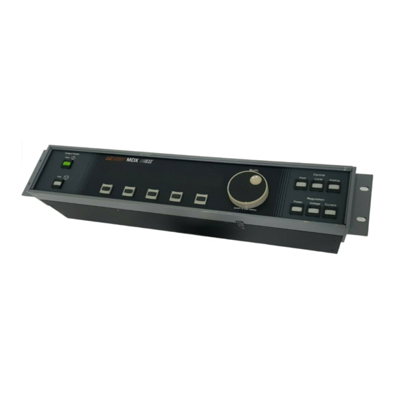
Page 118: Figure 6-10. Front View Of An Mdxii Active Remote Panel
® Advanced Energy Figure 6-10. Front view of an MDXII active remote panel 6-26 Panel Connection, Controls and Indicators 5700262-P... -
Page 119: Figure 6-11. Rear View Of An Mdxii Active Remote Panel
MDXII Power Supplies Figure 6-11. Rear view of an MDXII active remote panel 5700262-P Panel Connection, Controls and Indicators 6-27... - Page 120 ® Advanced Energy 6-28 Panel Connection, Controls and Indicators 5700262-P...
-
Page 121: Chapter 7. Serial Port Connection, Controls And Indicators
The serial port interface consists of a host computer attached to the rear panel of the MDXII unit through a 9-pin female, subminiature-D connector (see Figure 7-1 on page 7-2) next to an ™ eight-switch DIP. Advanced Energy recommends that you use shielded cables for connecting the serial port. -
Page 122: Pin Descriptions
® Advanced Energy MDXII units are shipped from the factory configured for either an AE Bus RS-232 or RS-485 protocol operation or a Profibus RS-485 protocol operation. “Configuration” on page 7-3 explains how an MDXII unit is configured for either protocol. -
Page 123: Configuration
MDXII Power Supplies Configuration AE BUS OR PROFIBUS OPERATION MDXII units are shipped from the factory configured for either an AE Bus RS-232 or RS-485 protocol operation or a Profibus RS-485 protocol operation. Refer to the following descriptions to connect for either an AE Bus or a Profibus serial port. DANGER: RISK OF DEATH OR BODILY INJURY: disconnect all sources of input power and wait a few minutes before working on this unit or anything connected to it. -
Page 124: Figure 7-3. Switches, Jumpers, And Connectors On The Logic Board
® Advanced Energy The jumpers are labeled P2, P3, P4, and P5. The red switch, labeled S1, is located just to the right of the jumpers. The ribbon cable, which connects the logic card at P6 or P9 to the back of the MDXII unit, is located in the upper right corner of the logic card. -
Page 125: Ae Bus Multidrop Operation
MDXII Power Supplies AE BUS MULTIDROP OPERATION When MDXII units are configured for RS-485 multidrop operation, the differential wire pair at each end of the network must be terminated with a set of terminating resistors. Each MDXII unit is shipped with terminating resistors that are installed but not jumpered on the logic board. If you are connecting an MDXII unit as an "end"... -
Page 126: Table 7-3. Setting Ae Bus Network Addresses
® Advanced Energy Use the first five mini-switches (A0 to A4) to specify the “address” of an MDXII unit, which a host computer must include in the message packet it sends. Each MDXII unit in a network must have a unique address. -
Page 127: Table 7-4. Setting Ae Bus Baud Rates
MDXII Power Supplies Table 7-3. Setting AE Bus Network Addresses (Continued) Address Position of min-switch down down down down down down down down down down down down down down down down down down down down down down down down down down down down... -
Page 128: Communications Protocol
® Advanced Energy COMMUNICATIONS PROTOCOL The AE Bus communications protocol uses pure binary data (nothing is coded into ASCII, for example), and is designed for multi-drop communications networks (networks that contain two or more nodes). The host computer is always the master unit. Slave units transmit only after receiving a message packet from the master, and then only to the master. -
Page 129: Figure 7-5. Representation Of A Message Packet
MDXII Power Supplies Figure 7-5 on page 7-9 shows the organization of these data fields in the AE Bus message packet. The subsequent paragraphs describe each data field. 7 6 5 4 3 2 1 0 7 6 5 4 3 2 1 0 7 6 5 4 3 2 1 0 7 6 5 4 3 2 1 0 7 6 5 4 3 7 6 5 4 3 2 1 0 7 6 5 4 3 2 1 0... - Page 130 ® Advanced Energy Data (Data Bytes) The Data field can contain from 0 to 255 bytes of binary data, which are interpreted in various ways, depending on the value that appears in the Command field. The Data field typically contains data or a CSR, depending on what was requested. Since some commands don't require accompanying data, this field is not always present.
-
Page 131: Figure 7-6. Ideal Communications Transaction
MDXII Power Supplies Figure 7-6. Ideal communications transaction First, the host computer sends a message packet to the MDXII unit. The packet contains one of the following: • A command that requests data or status information • A command and data that change a parameter setting •... -
Page 132: Figure 7-7. Example Communications Transaction
® Advanced Energy If the MDXII unit receives a request for data or status information, it gathers and sends the requested information. Otherwise, it evaluates the incoming command and sends a message packet that contains a 1-byte data value (CSR code) to the host (see Table 7-10 on page 7-57). -
Page 133: Profibus Interface
MDXII Power Supplies Profibus Interface ADDRESSES AND BAUD RATES A switch, labeled S1, is located on the rear of the MDXII unit. The S1 switch contains eight miniature switches (“mini-switches”). Figure 7-8. S1 switch on the MDXII rear panel Setting Profibus Network Addresses Use the S1 switch on the rear panel to set the unit’s address (see Figure 7-8 on page 7-13). -
Page 134: Communications Protocol
® Advanced Energy Setting Profibus Baud Rates The Profibus interface has an auto-baud detect feature, which will lock onto the baud rate the master (host computer) is trying to communicate with. These rates are in discrete steps from 9.6kbit up to 1.5Mbit. This interface will operate much like a modem or FAX machine in that at startup, there is a small delay while the interface traverses the different baud rates and then locks in. -
Page 135: Table 7-6. Configuration Of Profibus Upload Packet
MDXII Power Supplies Profibus Upload Packet During every Profibus data exchange, the unit supplies a 14-byte response to a download (“outbytes”) packet. Table 7-6 on page 7-15 shows this response or “upload packet.” These bytes are also known as “inbytes” at the Profibus master. Table 7-6. -
Page 136: Table 7-7. Definitions Of Profibus Upload Packet Status Bits
® Advanced Energy Table 7-7. Definitions of Profibus Upload Packet Status Bits Function Detail Byte 0 setpoint status 0 = out-of-setpoint 1 = setpoint okay OUTPUT.D status 0 = output is off 1 = output is on end of target life (EOTL) status... - Page 137 MDXII Power Supplies In the first status byte 0, bit 5 (the active toggle bit) indicates, in general, the status of the Profibus interface. After the unit has powered up, this bit’s continuous change indicates that the Profibus interface is ready. During operation, a cessation of this change indicates that a communication problem exists.
- Page 138 ® Advanced Energy Profibus Master-Specific Files Some PLCs use computer files called “type files” to compile their Profibus programs. Type files are device-specific and contain information on features found in that device. Thus a different type file should be defined for each Profibus device.
-
Page 139: Table 7-8. Example .Gsd File For An Mdxii Profibus
MDXII Power Supplies Table 7-8. Example .gsd File for an MDXII Profibus ;=============== ;GSD file for ;Product : Pinnacle and MDXII Profibus Interface ;Manufacturer: Advanced Energy Industries, Inc ;Status : Part Number: Revision: 2.0 ;=============== #Profibus_DP Vendor_Name = "Advanced Energy Industries"... -
Page 140: Terminating Profibus
® Advanced Energy TERMINATING PROFIBUS Profibus cables have termination resistors inside the cable connector itself. If the MDXII unit is the last node on the Profibus, switch these termination resistors “on” in the cable connector and ensure the termination resistors on the logic card are not jumpered. - Page 141 MDXII Power Supplies Table 7-9. AE Bus and Profibus Communications Commands (Continued) Command Used By Description Host Data ResponseData Bytes Bytes √ √ Sets dc output on; serial control must be selected (see Command 14). Read back this value with Command 161.
- Page 142 ® Advanced Energy Table 7-9. AE Bus and Profibus Communications Commands (Continued) Command Used By Description Host Data ResponseData Bytes Bytes √ √ Specifies the output setpoint setpoint level for whichever method of output regulation has been selected; accepts a value for a 15k unit (for example) of 0 to 1500 (15.00 kW, decimal...
- Page 143 MDXII Power Supplies Table 7-9. AE Bus and Profibus Communications Commands (Continued) Command Used By Description Host Data ResponseData Bytes Bytes √ √ Specifies how many volts Varc trip will constitute an arc (see level Command 31); accepts a value of 25 to 400 V (no implied decimal).
- Page 144 ® Advanced Energy Table 7-9. AE Bus and Profibus Communications Commands (Continued) Command Used By Description Host Data ResponseData Bytes Bytes √ √ Sets the life (in kilowatt- target life hours) of the target you specify as follows: AE Bus:...
- Page 145 MDXII Power Supplies Table 7-9. AE Bus and Profibus Communications Commands (Continued) Command Used By Description Host Data ResponseData Bytes Bytes √ √ Takes control of the MDXII control mode unit (if there is no control panel) or gives control to the User port;...
- Page 146 ® Advanced Energy Table 7-9. AE Bus and Profibus Communications Commands (Continued) Command Used By Description Host Data ResponseData Bytes Bytes √ √ Tells the MDXII unit program whether the source of source information for output regulation mode, setpoints, and ramp/run times is...
- Page 147 MDXII Power Supplies Table 7-9. AE Bus and Profibus Communications Commands (Continued) Command Used By Description Host Data ResponseData Bytes Bytes √ √ Specifies a factor by which filter level the analog signals LEVELIN.A, RAMPIN.A, voltage, and current readings from the internal supply will be filtered;...
- Page 148 ® Advanced Energy Table 7-9. AE Bus and Profibus Communications Commands (Continued) Command Used By Description Host Data ResponseData Bytes Bytes √ Programs one recipe of up to recipe steps, five steps tap, Byte 1 = number of target, steps in this recipe;...
- Page 149 MDXII Power Supplies Table 7-9. AE Bus and Profibus Communications Commands (Continued) Command Used By Description Host Data ResponseData Bytes Bytes √ Programs ramp times for the recipe: ramp recipe programmed with OR fast Command 20 ramp Byte 1 = the step number;...
- Page 150 ® Advanced Energy Table 7-9. AE Bus and Profibus Communications Commands (Continued) Command Used By Description Host Data ResponseData Bytes Bytes √ Programs run times for the recipe run or recipe programmed with fast run Command 20 Byte 1 = the step number;...
- Page 151 MDXII Power Supplies Table 7-9. AE Bus and Profibus Communications Commands (Continued) Command Used By Description Host Data ResponseData Bytes Bytes √ √ Tells the MDXII unit to logic crc calculate the logic software checksum; during the approximately 2 s it takes to calculate the checksum, the MDXII unit will not respond to front panel or serial port...
- Page 152 ® Advanced Energy Table 7-9. AE Bus and Profibus Communications Commands (Continued) Command Used By Description Host Data ResponseData Bytes Bytes √ Programs ramp times for the recipe: ramp recipe programmed with OR fast Command 20 ramp Byte 1 = the step number;...
- Page 153 MDXII Power Supplies Table 7-9. AE Bus and Profibus Communications Commands (Continued) Command Used By Description Host Data ResponseData Bytes Bytes √ Programs setpoints for the recipe: step, recipe programmed with regmode, Command 20 setpoint Byte 1: Bits 0-3 = the step number;...
- Page 154 ® Advanced Energy Table 7-9. AE Bus and Profibus Communications Commands (Continued) Command Used By Description Host Data ResponseData Bytes Bytes √ Programs run times for the recipe: run recipe programmed with OR fast run Command 20 Byte 1 = the step number;...
- Page 155 MDXII Power Supplies Table 7-9. AE Bus and Profibus Communications Commands (Continued) Command Used By Description Host Data ResponseData Bytes Bytes √ √ Tells the MDXII unit to turn HALO select on the HALO feature; accepts Boolean value of: 0 = turn halo off Non-zero value = turn halo on √...
- Page 156 ® Advanced Energy Table 7-9. AE Bus and Profibus Communications Commands (Continued) Command Used By Description Host Data ResponseData Bytes Bytes √ √ Command used in transductor transductor calibration; calibration accepts a value of 0 to 255 value Read back this value with Command 190.
- Page 157 MDXII Power Supplies Table 7-9. AE Bus and Profibus Communications Commands (Continued) Command Used By Description Host Data ResponseData Bytes Bytes √ Sets the Iarc or Varc Varc/Iarc counter; accepts a value of 0 count to 999 Bytes 1 and 2 = Varc count limit Bytes 3 and 4 = Iarc count limit...
- Page 158 ® Advanced Energy Table 7-9. AE Bus and Profibus Communications Commands (Continued) Command Used By Description Host Data ResponseData Bytes Bytes Note: Commands 128 through 209 request information from the MDXII unit. The values under “Response Data Bytes” (columns 7 and 8) reflect the number of response data bytes if the requesting command has executed successfully.
- Page 159 MDXII Power Supplies Table 7-9. AE Bus and Profibus Communications Commands (Continued) Command Used By Description Host Data ResponseData Bytes Bytes √ √ Requests the dual setpoint request dual recipe (set with Command recipe setpoint Bytes 1 and 2 = setpoint side A Byte 3 = regulation mode...
- Page 160 ® Advanced Energy Table 7-9. AE Bus and Profibus Communications Commands (Continued) Command Used By Description Host Data ResponseData Bytes Bytes √ √ Requests control mode (set request with Command 14) control mode √ √ Requests the number of the...
- Page 161 MDXII Power Supplies Table 7-9. AE Bus and Profibus Communications Commands (Continued) Command Used By Description Host Data ResponseData Bytes Bytes √ √ 2 bytes = mainframe request status flags mainframe 2 bytes = configurable status options 1 byte = error code returned from non- volatile memory check Error codes:...
- Page 162 ® Advanced Energy Table 7-9. AE Bus and Profibus Communications Commands (Continued) Command Used By Description Host Data ResponseData Bytes Bytes √ √ 20 = regulation mode request 21 = setpoint mainframe status = rmode/setpoint (continued) 24 = ten watt hours...
- Page 163 MDXII Power Supplies Table 7-9. AE Bus and Profibus Communications Commands (Continued) Command Used By Description Host Data ResponseData Bytes Bytes √ √ Requests status of most request recent output on sequence output on 0 = output on sequence status 5 = output on sequence aborted because output off has been requested...
- Page 164 ® Advanced Energy Table 7-9. AE Bus and Profibus Communications Commands (Continued) Command Used By Description Host Data ResponseData Bytes Bytes √ √ Requests report on process request status, including faults. process 1st status byte: status Bit 0 = Ramp is active...
- Page 165 MDXII Power Supplies Table 7-9. AE Bus and Profibus Communications Commands (Continued) Command Used By Description Host Data ResponseData Bytes Bytes √ √ Bit 6 = Vacuum request interlock open process Bit 7 = Auxiliary status interlock open (continued) 3rd status byte - fault flags* Bit 0 = Momentary power fluctuation Bit 1 = Soft-start failure...
- Page 166 ® Advanced Energy Table 7-9. AE Bus and Profibus Communications Commands (Continued) Command Used By Description Host Data ResponseData Bytes Bytes √ √ until 1) the condition is request resolved and 2) the process condition is reported to status the host computer.
- Page 167 MDXII Power Supplies Table 7-9. AE Bus and Profibus Communications Commands (Continued) Command Used By Description Host Data ResponseData Bytes Bytes √ √ Requests system request configuration status config status 1st status byte: Bit 0 = Varc shutdown: 0 = no, 1 = yes Bit 1 = ARC CHECK active: 0 = no, 1 = yes Bit 2 = C HOLD: 0 =...
- Page 168 ® Advanced Energy Table 7-9. AE Bus and Profibus Communications Commands (Continued) Command Used By Description Host Data ResponseData Bytes Bytes √ √ Requests output setpoint request level (set with Command 6) setpoint/ and whatever method of regulation output regulation has been...
- Page 169 MDXII Power Supplies Table 7-9. AE Bus and Profibus Communications Commands (Continued) Command Used By Description Host Data ResponseData Bytes Bytes √ Requests programmed limits request for output power, voltage, power, and current voltage, Bytes 1 and 2 = power current limit limits...
- Page 170 ® Advanced Energy Table 7-9. AE Bus and Profibus Communications Commands (Continued) Command Used By Description Host Data ResponseData Bytes Bytes √ √ Requests current level at request which the MDXII unit will current arc assume an arc exists and turn...
- Page 171 MDXII Power Supplies Table 7-9. AE Bus and Profibus Communications Commands (Continued) Command Used By Description Host Data ResponseData Bytes Bytes √ √ Requests how much time is request out- left until the output is turned of-setpoint off because it is out of time setpoint Byte 1 = minutes left...
- Page 172 ® Advanced Energy Table 7-9. AE Bus and Profibus Communications Commands (Continued) Command Used By Description Host Data ResponseData Bytes Bytes √ √ Requests the programmed 2 or request ramp time (set with programmed Command 21) for the ramp specified step...
- Page 173 MDXII Power Supplies Table 7-9. AE Bus and Profibus Communications Commands (Continued) Command Used By Description Host Data ResponseData Bytes Bytes √ √ Requests how long the request out- MDXII unit is programmed of-setpoint to produce output that is not interval equal to the programmed setpoint level before shutting...
- Page 174 ® Advanced Energy Table 7-9. AE Bus and Profibus Communications Commands (Continued) Command Used By Description Host Data ResponseData Bytes Bytes √ √ Requests the ramp time that request is specified through the User external port (external program ramp source) and therefore will be...
- Page 175 MDXII Power Supplies Table 7-9. AE Bus and Profibus Communications Commands (Continued) Command Used By Description Host Data ResponseData Bytes Bytes √ √ Requests the revision level request s/w of the mainframe software; revision returning packet will contain level— 3 ASCII characters: one mainframe letter, followed by a two- digit number...
- Page 176 ® Advanced Energy Table 7-9. AE Bus and Profibus Communications Commands (Continued) Command Used By Description Host Data ResponseData Bytes Bytes √ √ Requests total amount of request total energy (in kilowatt-hours) energy delivered by the MDXII unit output √...
-
Page 177: Serial Port Indicators
MDXII Power Supplies SERIAL PORT INDICATORS AE Bus Indicators COMMAND STATUS RESPONSE (CSR) CODES When you invoke a command through a serial port using an AE Bus protocol, a value is returned in response to the command. The meaning of each value is explained in Table 7-10 on page 7-57. -
Page 178: Profibus Indicators
® Advanced Energy Table 7-10. AE Bus Command-Status Response (CSR) Codes (Continued) Value Meaning Recipe is active Command not accepted because no such command exists Profibus Indicators PROFIBUS-SPECIFIC ERRORS In the event of a Profibus error, the unit turns output power off and displays the appropriate error message (see page 8-10). - Page 179 MDXII Power Supplies When you request the Profibus debug screen, the panel display shows two rows of hexadecimal numbers. To better understand this information, please examine the following example. In the example, the first four bytes in sequence (left to right) represent the last recorded download bytes (from the Profibus master).
- Page 180 ® Advanced Energy 7-60 Serial Port Connection, Controls and Indicators 5700262-R...
-
Page 181: Chapter 8. Troubleshooting And Customer Support
MDXII Power Supplies Chapter Chapter Troubleshooting and Customer Support BEFORE YOU CALL AE CUSTOMER SUPPORT If you believe you are experiencing a problem with your MDXII unit, first refer to the information in this section to help you troubleshoot problems. This section provides 1) troubleshooting checklists and 2) lists of messages or other indicators of problems with suggested actions to take. -
Page 182: Checks With The Unit Powered On
® Advanced Energy 3. Ensure that the unit is connected to its input power source (see “Input Power Connection” on page 4-7). 4. Ensure that input power meets specifications (see “Specifications” on page 3-1). 5. Ensure that no system-related circuit breakers are tripped. -
Page 183: Checks If The Output Does Not Turn On
MDXII Power Supplies CHECKS IF THE OUTPUT DOES NOT TURN ON If the output does not turn on, possibly a fault condition exists or an internal software configurable parameter has been changed. Do the following: 1. First check to see whether a fault message is displayed. If so, take the action listed in Table 9-2 on page 9-15. -
Page 184: Status Indicators
® Advanced Energy Table 8-1. General Fault Conditions Fault Condition Explanation Suggested Action Serial port will not commu- The address and baud rate Verify the address and baud nicate between the host computer rate switch selections on the and the MDXII unit is mis- rear of the unit (see informa- matched. -
Page 185: Table 8-2. Panel Leds And Fault Messages
MDXII Power Supplies Table 8-2. Panel LEDs and Fault Messages Problem Indicators Explanation Suggested Action Passive Control Panel Fault Panel LED On Message “A/D Conversion Fail- Hardware logic Cycle power to the unit. ure” board failure If the fault message persists, call AE Customer Support. - Page 186 ® Advanced Energy Table 8-2. Panel LEDs and Fault Messages (Continued) Problem Indicators Explanation Suggested Action Passive Control Panel Fault Panel LED On Message BUS LOW “Bus 1 Low” Internal MDXII bus Press the STOP switch to RIGHT 1 voltage input line is clear the fault message.
- Page 187 MDXII Power Supplies Table 8-2. Panel LEDs and Fault Messages (Continued) Problem Indicators Explanation Suggested Action Passive Control Panel Fault Panel LED On Message “Incorrect Tap The tap that was Press the STOP switch to Selected” selected when the clear the fault message. recipe you are trying Change the tap setting to run was...
- Page 188 ® Advanced Energy Table 8-2. Panel LEDs and Fault Messages (Continued) Problem Indicators Explanation Suggested Action Passive Control Panel Fault Panel LED On Message “Invalid Regulation An invalid method of Specify a valid method of Mode” output regulation has regulation from the User been selected from port.
- Page 189 MDXII Power Supplies Table 8-2. Panel LEDs and Fault Messages (Continued) Problem Indicators Explanation Suggested Action Passive Control Panel Fault Panel LED On Message SETPOINT “Out-of-setpoint” Output was turned Press the STOP switch to off because the clear the fault message. MDXII unit was not Increase the setpoint able to produce...
- Page 190 ® Advanced Energy Table 8-2. Panel LEDs and Fault Messages (Continued) Problem Indicators Explanation Suggested Action Passive Control Panel Fault Panel LED On Message “Profibus Master The Profibus master Have a Profibus master Released Slave” has stopped establish communication communicating with with the MDXII unit.
- Page 191 MDXII Power Supplies Table 8-2. Panel LEDs and Fault Messages (Continued) Problem Indicators Explanation Suggested Action Passive Control Panel Fault Panel LED On Message “Stuck Pushbutton” One (or more) Push each switch to control panel verify the error and/or to switches is stuck.
-
Page 192: Serial Port Command-Status Response (Csr) Codes
® Advanced Energy Table 8-2. Panel LEDs and Fault Messages (Continued) Problem Indicators Explanation Suggested Action Passive Control Panel Fault Panel LED On Message 7 SEQ Indicates maximum DISPLAY unit power (for example, “15” = 15.0kW) INPUT Indicates the input... -
Page 193: User Port Output Signals
MDXII Power Supplies Table 8-3. AE Bus Command-Status Response (CSR) Codes (Continued) Value Meaning Command not accepted because this feature is not available on your unit (see “Understanding the Optional Software Features” on page 2-19) Command not accepted because the control panel has priority Invalid regulation mode Invalid control mode (same as Value 1 above) Target life consumed... -
Page 194: Ae Customer Support
® Advanced Energy AE CUSTOMER SUPPORT Please contact one of the following offices if you have questions: Table 8-5. Customer Support Locations Office Telephone AE, World Headquarters Phone: 800.446.9167 1625 Sharp Point Drive Fax: 970.407.5981 Fort Collins, CO 80525 USA Email: technical.support@aei.com... -
Page 195: Returning Units For Repair
® To ensure years of dependable service, Advanced Energy products are thoroughly tested and designed to be among the most reliable and highest quality systems available worldwide. -
Page 196: Authorized Returns
® Advanced Energy Authorized Returns Before returning any product for repair and/or adjustment, call AE Customer Support and discuss the problem with them. Be prepared to give them the model number and serial number of the unit as well as the reason for the proposed return. This consultation call will allow Customer Support to determine if the unit must actually be returned for the problem to be corrected. -
Page 197: Chapter 9. User Port Connection, Controls And Indicators
All signal inputs in the User port have filtering to reject noise higher in frequency than 1 ms. ™ Advanced Energy recommends that you use shielded cables for connecting the User port. (The MDXII unit uses Schmidt triggers for all digital inputs to prevent false triggering.) When you connect the User port, you may want to take advantage of several different wiring options. -
Page 198: Figure 9-2. Wiring For Externally Monitoring The Output
® Advanced Energy LEVEL OUT.A V OUT.A P OUT.A I OUT.A KWH OUT.A OUT COM.A 1253 Figure 9-2. Wiring for externally monitoring the output User Port Connection, Controls and Indicators 5700262-R... -
Page 199: External Programming Of Ramp Timer And Setpoint
MDXII Power Supplies EXTERNAL PROGRAMMING OF RAMP TIMER AND SETPOINT Figure 9-3 on page 9-3 shows how to wire the input lines so you can specify output setpoint level and ramp time from an external source. You also need to specify method of output regulation, described on page 5-1, and read about pins 5 and 6 on page 9-9. -
Page 200: External On/Off Control For Dual Line Units
® Advanced Energy EXTERNAL ON/OFF CONTROL FOR DUAL LINE UNITS Some MDXII units are shipped with User port pins 7 and 14 configured so that the output on and off signals can be separately controlled (hence the term “dual-line”). Figure 9-5 on page 9-4 shows how to wire these units for dual-line or single-line on/off control. -
Page 201: Cheater Plug
MDXII Power Supplies CHEATER PLUG The “cheater plug” (see Figure 9-6 on page 9-5) that came attached to the User port connector lets you run the MDXII unit essentially right out of the box, without making any wiring adjustments. You can continue to use the cheater plug if you want to ignore (“cheat”) the interlock lines;... -
Page 202: User Port Grounding
® Advanced Energy User Port Grounding The User port features multiple ground pins. All of these pins are “single point connected” internally to analog, digital, and chassis ground on the MDXII logic card. The simplest ground connection system for these pins ensures a well-connected ground at the MDXII chassis. -
Page 203: Signal Pin Descriptions
These 0 to 15 V signals tell an external ® CTHSW 2.D output device (such as the Advanced Energy cathode-switching box) which of eight targets the MDXII unit has been set to decrement (as specified from either the control panel or pins 4, 34, and 35). - Page 204 ® Advanced Energy Table 9-1. User Port Signal Pins (Continued) Signal Return Name Signal Description Type OUTPUT.D digital (or UNIT READY, see note below). output When high, this 0 to 15 V signal indicates that the output is off and that the contactor is open, if contactor hold has not been selected.
- Page 205 MDXII Power Supplies Table 9-1. User Port Signal Pins (Continued) Signal Return Name Signal Description Type TARGET 0.D digital Use these signals to specify one of eight TARGET 2.D input possible targets. The MDXII TARGET 1.D microprocessor uses this information to keep track of the kilowatt usage for all eight targets.
- Page 206 ® Advanced Energy Table 9-1. User Port Signal Pins (Continued) Signal Return Name Signal Description Type RMT ON.D digital Use this signal to turn on output from input the user-remote interface. You must first select ANALOG from the control panel...
- Page 207 MDXII Power Supplies Table 9-1. User Port Signal Pins (Continued) Signal Return Name Signal Description Type RMT OFF.D digital Pull this signal high to override all input commands, force the MDXII unit to shut off output power, open the main contactor (unless contactor hold has been selected), and reset the unit after all fault conditions except interlock,...
- Page 208 ® Advanced Energy Table 9-1. User Port Signal Pins (Continued) Signal Return Name Signal Description Type 15 V Use this signal to supply 15 V dc; it will source a maximum of 100 mA. ILK COM.D digital This signal is a dedicated return to...
- Page 209 MDXII Power Supplies Table 9-1. User Port Signal Pins (Continued) Signal Return Name Signal Description Type I OUT.A analog This signal provides a fully buffered output signal, representing output current from your unit; maximum current depends on which tap is selected). Ω...
- Page 210 ® Advanced Energy Table 9-1. User Port Signal Pins (Continued) Signal Return Name Signal Description Type LEVEL OUT.A analog This signal provides a fully buffered output signal representing the MDXII unit's programmed setpoint level. This signal will source and sink 5 mA through a 2- Ω...
-
Page 211: Table 9-2. Standard User Port Analog Signal Scalings
MDXII Power Supplies Table 9-2. Standard User Port Analog Signal Scalings LEVEL IN.A V OUT.A I OUT.A P OUT.A LEVEL OUT.A Notes 2 & 3 MDXII 0 - 10 V 0 - 10 V 0 - 10 V 0 - 10 V Same scaling as Notes 1 &... - Page 212 ® Advanced Energy 9-16 User Port Connection, Controls and Indicators 5700262-R...
-
Page 213: Appendix A. Mdxii 18P Unit
MDXII Power Supplies Appendix Chapter MDXII 18P Unit This appendix describes specifications, operations, or features that are either unique to the MDXII 18P unit or are different than those described for the MDXII 15k or 30k units elsewhere in this manual. In addition, this appendix contains illustrations of the MDXII 18P panels. -
Page 214: Electrical Specifications
® Advanced Energy Electrical Specifications Table A-2. MDXII 18P Electrical Specifications Input Voltages (internally Either 380/400/415 V ac ± 10% or ∆ selected) 440/460/480 V ac ±10%, 50/60 Hz, three-phase Y or maximum ground leakage current less than 3.5mA. Input Current... -
Page 215: Environmental Specifications
MDXII Power Supplies Environmental Specifications Table A-4. MDXII 18P Climatic Specifications Temperature Relative Humidity Air Pressure Class 3K3 Class 3K2 Class 3K3 Operating (Note 1) (Note 2) 0°C to +40°C 20% to 80% 80 kPa to 106 kPa +32°F to +104°F +6 g/m to 23.5 g/m 800 mbar to 1060 mbar... -
Page 216: Fast User Port
® Advanced Energy Fast User Port The MDXII 18P unit supports a “Fast User Port,” which provides faster updates on critical information through the User port. Changes from the standard User port are as follows: • Pin 7 (RMT ON.D): this signal pin is interrupt-driven instead of polled. -
Page 217: Vhalo
MDXII Power Supplies Table A-6. MDXII 18P Maximum Tap Setting Voltages and Currents Max. Output Maximum Output Number Voltage Current MDXII 15k MDXII 18k tap 1 312 V to 400 V 48.00 A 48.00 A tap 2 400 V to 500 V 37.50 A 45.00 A tap 3... -
Page 218: 18P Unit Illustrations
® Advanced Energy 18P UNIT ILLUSTRATIONS Figure A-1. Active front panel of an MDXII 18P unit 5700262-R... -
Page 219: Figure A-2. Passive Panel Of An Mdxii 18P Unit
MDXII Power Supplies Figure A-2. Passive panel of an MDXII 18P unit 5700262-R... -
Page 220: Figure A-3. Rear View Of An Mdxii 18P Unit
® Advanced Energy Figure A-3. Rear view of an MDXII 18P unit 5700262-R... -
Page 221: Appendix B. Master/Slave
MDXII Power Supplies Appendix Chapter Master/Slave This appendix describes specifications, operations, or features that are either unique to the MDXII master/slave unit or are different than those described for the MDXII 15k or 30k units elsewhere in this manual. The master/slave system can deliver anywhere from 15kW (a single master unit) to 120kW ( a 30kW master and three 30kW slaves). -
Page 222: Table B-2. Output Power
® Advanced Energy Table B-2. Output Power System Configuration Number Number Power of 15 kW of 30 kW Master Slave 1 Slave 2 Slave 3 (kW) Units Units Table B-3. Output Display Accuracy (based on 30 kW master) Master Slave 1... -
Page 223: Operations
MDXII Power Supplies Table B-5. Output Parameters Max. Maximum Current for Each Tap Power Tap 1 Tap 2 Tap 3 Tap 4 Tap 5 Tap 6 (kW) 400 V 500 V 625 V 800 V 1000 V 1250 V 48.0 37.5 30.0 24.0... - Page 224 ® Advanced Energy Table B-6. Pin Descriptions Name Signal Type Description SL OFF.D output from the It is used with pin 22 (SL ON.D) to turn master unit, 0 the slave units on and off. to 15V SL OFF.D Status SL ON.D...
- Page 225 MDXII Power Supplies Table B-6. Pin Descriptions Name Signal Type Description SL1 ID.A input to the This 0 to 8 V input signal from slave 1 master unit, 0 informs the master what maximum power to 8 V level is available: 4 V+/- 1 V represents a 15 kW unit and 8 V+/- 1 V represents a 30 kW unit.
- Page 226 ® Advanced Energy Table B-6. Pin Descriptions Name Signal Type Description MSTR PWM output from the This 0 to 15 V output signal turns the ON.D master unit, 0 output power in each slave on and off. By to 15V...
- Page 227 MDXII Power Supplies Table B-6. Pin Descriptions Name Signal Type Description SL3 FAULT.D input to the This 0 to 15 V input signal from the slaves master unit, 0 reports a fault in slave 3. A slave fault can to 15 V be due to bus high, bus low, overtemp, interlock, or failure of the main contactor to close.
-
Page 228: Indicators
® Advanced Energy Indicators The following indicators appear on the front panel of your unit. Table B-7. LED Descriptions Description Lights if input power is on. Input Power Lights for 0.1 s if an arc occurs. Lights if the MDXII unit is not operating within setpoint. - Page 229 MDXII Power Supplies Table B-8. Fault Messages (Continued) Message Explanation/Response SL3 FAULT Slave unit 3 is reporting a fault (bus high, bus low, over- temperature, or loss of cable). Press the STANDBY switch to clear the message. SLAVE BUS ERROR The slave failed to report that it was ready (SL RDY.D, pin 16).
-
Page 230: Host/Mdxii Communications Commands
® Advanced Energy Host/MDXII Communications Commands Table B-9. Communications Commands Command Description and Comments Requests report on process status. Returning packet rpt process status contains four data bytes (8-bit value). see the illustration below and on the next page. Note: If the run is active bit and the fast run is active bit (bit... - Page 231 MDXII Power Supplies Table B-9. Communications Commands (Continued) Command Description and Comments Command 162 Fourth Status Byte--fault flags continued 0 = Bus 1 low 1 = Bus 2 low 2 = Slave 1 fault 3 = Slave 2 fault 4 = Slave 3 fault 5 = Unassigned interrupt 6 = Invalid reg.
-
Page 232: Figure B-1. Rear View Of A 15 Kw Slave
® Advanced Energy Figure B-1. Rear view of a 15 kW slave. (The Prior and Next connectors for the 30 kW unit are the same as for the 15 kW unit.) B-12 5700262-R... -
Page 233: Making Rear Panel Connections
MDXII Power Supplies Making Rear Panel Connections MDXII master/slave systems operates more reliably and is less sensitive to spurious noise if both the MDXII chassis and the system are grounded. The preferred method of chassis grounding is to daisy-chain a flat copper braid of AWG-10 equivalence between units. Use only one lead to connect the system ground block to the daisy-chained units. -
Page 234: Running As A Master/Slave System
® Advanced Energy Figure B-3. DIP switch block RUNNING AS A MASTER/SLAVE SYSTEM • Remove the top cover and safety shield from the card cage only. • Locate the DIP switch block on the upper right hand corner of the transductor board (the card farthest from the side of the unit). -
Page 235: Running As A Stand Alone Supply
MDXII Power Supplies RUNNING AS A STAND ALONE SUPPLY • Remove the slave. • Place the slave termination plug on the slave port on the master. • Remove the top cover and the safety shield from the card cage only. •... -
Page 236: Figure B-4. Interconnect Cable Connection
® Advanced Energy Figure B-4. Interconnect cable connection Note: The interconnect cable is connected to the master unit’s Slave port and the slave unit’s Prior port. Depending on how many slaves are in your system, either another interconnect cable or the termination plug will be connected to the Next port. -
Page 237: Start-Up Procedure
MDXII Power Supplies Start-up Procedure Be sure to turn on the circuit breaker at the rear of the slave units before you turn on the circuit breaker of the master unit. The INPUT POWER LED lights on each unit. Master/Slave Operation A master/slave system consists of one 30 kW master unit and from one to three slave units. -
Page 238: Target Controls
® Advanced Energy The output control signal (Slave pins 15 and 34) from the master unit determines the output for the system. Each slave is told what percentage of its maximum output to produce. For example, a 15 kW slave unit produces 7.5kW when commanded to produce 50%; a 30 kW slave produces 15 kW. -
Page 239: Tap Settings
MDXII Power Supplies Tap Settings The MDXII is equipped with six internal voltage taps so that six different output ranges can be selected for each master/slave system. Each MDXII leaves the factory set at tap 4, but you can easily select a different tap from any of the three interfaces. The following table indicates the maximum current that can be produced at each tap. - Page 240 ® Advanced Energy B-20 5700262-R...
- Page 241 MDXII Power Supplies Index 6, 10, 22 Numerics delay 6, 10 density 1600 V in tap 6 suppression 18kW power 6, 11, 22, 37 trip levels 18P unit ARC functions contactor closure style 18, 16, 37 ASCII feature electrical specifications authorized returns, warranty environmental specifications auto-contactor software...
- Page 242 MDXII Power Supplies connector wiring external monitoring of output data consistency, Profibus external on/off control debug menu, Profibus external programming of ramp time and Deko option setpoint 6, 10, 22 delay and density, arcs floating output disabling a recipe negative output disconnecting normal interlock connection 2, 3...
- Page 243 MDXII Power Supplies icons User port in user manual noise prevention 1 on unit wiring options 1 ideal communications transaction, serial port interfaces control panel identifying software versions remote indicators interlock string, monitor AE Bus command status response codes internal program source 57, 12 inverter section 7, 4...
- Page 244 MDXII Power Supplies MORE functions return parameters to default 17 multidrop configuration, AE Bus system statistics 21, 17 user input string 16 8, 7, 12, 22, 11 tap settings negative output connection 18P unit 4 noise prevention, User port selecting correct 8 normal interlock connection target controls seeing which is active 9...
- Page 245 MDXII Power Supplies VARC/IARC counters enabled in user serial port port User port VHALO Pinnacle-style mini-panel options, operational positive output connection 2 setpoint, 4 target power auto-contactor 18kW Deko maximum output limit setpoint.d output out-of-setpoint regulation 4, 25 allowable deviation power supply enhancements 17, 27 output...
- Page 246 MDXII Power Supplies HALO checks ramp time precautions run time standards serial port timeout value security of system tap settings seeing which target is active VHALO selecting menu functions on control panel rear clearance requirements selecting the correct tap rear panel connections selections, control panel menu grounding ARC functions...
- Page 247 MDXII Power Supplies user memo string port setpoint VHALO dual software versions, identifying external programming spacing requirements 7, 8, 9, 22 level rear clearance manual top and side clearance programming one or more specifications setpoint.d option electrical setting and resetting lock code environmental setting baud rates physical...
- Page 248 MDXII Power Supplies 8, 12, 22, 11 tap settings general fault conditions 18P unit output does not turn on 2, 7 maximum currents panel LEDs and fault messages ranges User port status signals recipe two-line display selecting correct 8, 4 target controls unit enable target life counter...
- Page 249 MDXII Power Supplies output current signal external output monitoring output power signal external programming output voltage signal floating output program HALO negative output program output level normal interlock connection select tap positive output set active target set output regulation set ramp time signal pin descriptions standard analog signal settings status signals...
Need help?
Do you have a question about the MDX II and is the answer not in the manual?
Questions and answers