Siemens SIPROTEC 5 Manual
Fault recorder, v7.50 and higher
Hide thumbs
Also See for SIPROTEC 5:
- Manual (272 pages) ,
- Operation manual (218 pages) ,
- Technical data manual (129 pages)
Table of Contents
Advertisement
Quick Links
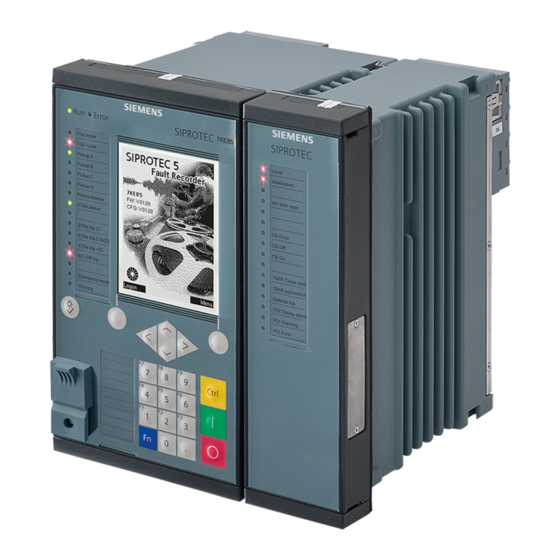
SIPROTEC 5
Fault Recorder
7KE85
V7.50 and higher
Manual
C53000-G5040-C018-5
Preface
Open Source Software
Table of Contents
Introduction
Basic Structure of the Function
System Functions
Applications
Power-System Data
Function-Group Types
Fault Recorder
Supervision Functions
Measured and Energy Values
Functional Tests
Technical Data
Appendix
Glossary
Index
1
2
3
4
5
6
7
8
9
10
11
A
Advertisement
Table of Contents


Need help?
Do you have a question about the SIPROTEC 5 and is the answer not in the manual?
Questions and answers