Sign In
Upload
Manuals
Brands
TOHATSU Manuals
Outboard Motor
BFT 250A
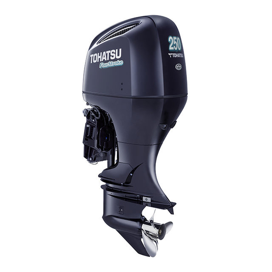
TOHATSU BFT 250A Outboard Motor Manuals
Manuals and User Guides for TOHATSU BFT 250A Outboard Motor. We have
4
TOHATSU BFT 250A Outboard Motor manuals available for free PDF download: Service Manual, Owner's Manual, Manual
TOHATSU BFT 250A Service Manual (639 pages)
Brand:
TOHATSU
| Category:
Outboard Motor
| Size: 18 MB
Table of Contents
Table of Contents
7
General Information
11
Specifications
12
Lower Unit
13
Service Information
17
Maintenance
18
Standard Torque Values
23
Special Tools
24
3. Maintenance
59
Maintenance Schedule
60
Tools
61
Change
62
Engine Oil Level Inspection/Oil
62
Engine Oil Filter Replacement
64
Gear Case Oil Change
65
Timing Belt Inspection
66
Alternator Belt Inspection
67
Adjustment
69
Throttle Linkage Inspection
69
Valve Clearance
73
Spark Plug Inspection
75
Gear Case
77
Inspection
77
Propeller and Cotter Pin
77
Lubrication
83
Fuel Filter (Low Pressure Side) Inspection/Replacement
85
Water Separator Inspection
85
Fuel Filter (High Pressure Side) Inspection/Replacement
87
Fuel Line Inspection
88
Replacement
88
Battery and Cable Connection
89
Crankcase Breather
89
Nuts, Bolts, Fasteners
89
Impeller Housing Inspection
90
Water Passage Cleaning
90
Water Pump Inspection
90
Adjustment
91
Emergency Stop Switch
91
Inspection
91
Power Trim/Tilt Inspection
91
Shift Control Cable Inspection
91
Troubleshooting
93
5. Fuel System
123
Tools
124
Service Precautions
125
System Location
131
Piping Connections
132
Circuit Diagram
133
Ecm Terminal Arrangement
135
Dtc Troubleshooting
137
Mil Troubleshooting
167
Fuel Pressure Relieving
188
Installation
191
Cleaning
194
Installation
194
Intake Manifold Removal
194
Fuel Injectors/Fuel Pressure Regulator
200
Fuel Pump (High Pressure Side)/Vapor Separator Removal/Installation
208
Air Vent Strainer/Air Vent Tube Removal
214
Water Separator/Water Level Sensor Removal/Installation/Cleaning
215
Exhaust Manifold Removal
217
Installation
217
Exhaust Manifold Anode Removal
219
Iat Sensor Removal/Installation
220
Installation
220
Map Sensor Removal/Installation
220
Emt Sensor Removal/Installation
221
Iac Valve Removal/Installation
221
Ho2S Removal/Installation
222
Installation
223
Vtec Solenoid Valve Removal
223
Ckp Sensor Removal/Installation
224
Fuel System
224
Iab Control Solenoid Valve Removal
224
Installation
224
Cmp Sensor Removal/Installation
225
Eop Switch (High Pressure Side) Removal
225
Installation
225
Eop Switch (Low Pressure Side) Removal
226
Installation
226
Knock Sensor Removal
226
Ebt Sensor Removal/Installation
227
Installation
227
Fuel Pump (High Pressure Side)/Fuel Filter Disassembly/Assembly
228
Assembly
231
Vapor Separator Disassembly
231
Fuel Pressure Measurement
232
Fuel Pressure Regulator
233
Inspection
233
Fuel Pump (Low Pressure Side)
234
Inspection
234
Fuel Pump (High Pressure Side)
235
Inspection
235
Vapor Separator Inspection
237
Fuel Injector Inspection
238
Throttle Body Inspection
239
Iab Control Solenoid Valve
240
Inspection
240
Eop Switch (High Pressure Side)
242
Inspection
242
Eop Switch (Low Pressure Side)
243
Inspection
243
Ebt/Emt Sensor Inspection
244
Ckp Sensor Inspection
245
Cmp Sensor Inspection
245
Water Level Sensor Inspection
246
Iac Valve Inspection
247
Inspection
247
Vtec Spool Solenoid Valve
247
Ho2S Inspection
248
Intake Manifold Stud Bolt
249
Replacement
249
6. Engine Cover/Cover Lock
251
Engine Cover/Cover Lock
251
Component Location
252
Front Separate Cover Removal
253
Installation
253
L./R. Engine under Cover Removal
253
Installation
256
Cover Locking Cable Removal
256
Installation
259
Engine Cover Bracket Removal
259
Installation
260
Power Tilt Switch Removal
260
Front Cover Bracket Removal
260
Damper Hook Removal
262
Installation
262
Side Cover Bracket Disassembly
262
Assembly
265
Damper Hook Disassembly
265
Damper Hook Adjustment
266
Under Cover Seal B
266
Replacement
266
7. Charging System
267
Charging System
267
System Location
268
System Diagram
268
Junction Box
268
Tools
269
Alternator Removal
271
Installation
271
Alternator Disassembly
272
Assembly
272
Alternator Inspection
281
Ignition System
283
9. Starting System
287
Starting System
288
System Diagram
288
System Location
288
Installation
291
Starter Motor Removal
291
Assembly
292
Installation
292
Neutral Switch Removal
292
Starter Motor Disassembly
292
Starter Motor Inspection
302
Neutral Switch Inspection
306
10. Other Electrical
307
Other Electrical
307
System Location
308
Installation
310
Electric Parts Case Removal
310
Installation
311
Ecm Removal/Installation
311
Ecm Bracket Removal
311
Installation
312
Power Tilt Relay/Power Tilt Relay Case Removal/Installation
312
Switch Panel Indicator Wire
314
Harnesses Removal
314
Installation
314
Relay Removal/Installation
316
Main/Starter Relay Inspection
317
Fuel Pump Relay Inspection
317
Fuse/Relay Junction Box
318
Inspection
318
Power Tilt Relay Inspection
320
Trim Angle Sensor Inspection
321
11. Cooling System
323
Cooling System
323
Component Location
324
Tools
325
Water Line Description
326
Thermostat Removal
327
Installation
327
Water Jacket Removal
328
Installation
328
Water Pump Removal
331
Installation
331
Cylinder Sleeve Water Jacket Anode Removal/Installation
337
Relief Valve Disassembly
339
Assembly
339
Flush Valve Disassembly
340
Assembly
340
Thermostat Inspection
341
12. Lubrication System
343
Lubrication System
343
Component Location
344
Lubrication System Diagram
345
Tools
346
Oil Filler Extension Removal
347
Installation
347
Oil Level Gauge Cover Removal
347
Removal/Installation
347
Oil Pump Removal/Installation
351
Assembly
353
Oil Pressure Test
354
Oil Pump Inspection
355
13. Engine Removal/Installation
357
Engine Removal/Installation
357
Component Location
358
Engine Removal
360
Tool
361
Cylinder Head
361
Engine Installation
362
14. Cylinder Head
369
Component Location
370
Tools
372
Timing Belt Drive/Driven Pulley Removal/Installation
374
Cylinder Block
382
Cylinder Head Cover Removal
387
Installation
387
Cylinder Head Removal
390
Installation
390
Cylinder Head Disassembly
393
Assembly
393
Assembly
396
Cylinder Compression Test
401
Cylinder Head Inspection
401
Valve Guide Replacement
410
Valve Seat Reconditioning
412
15. Cylinder Block
415
Component Location
416
Tools
417
Cylinder Block Anode Removal
418
Flywheel Removal/Installation
418
Installation
418
Flywheel Inspection
440
Bearing Selection
450
16. Gear Case (Standard Rotation)
455
Gear Case (Standard Rotation)
455
Component Location
456
Tools
474
Gear Case (Counter Rotation)
505
Propeller Removal
509
Installation
509
Mount
513
GEAR CASE/EXTENSION SEPARATOR (XXA Type) REMOVAL/INSTALLATION
516
INSTALLATION (XA and XXA Types)
516
Installation
529
Vertical Shaft/Removal
529
Installation
532
Assembly
534
Propeller Shaft Holder
534
Disassembly/Assembly
534
Vertical Shaft Disassembly
535
Assembly
535
Shim Selection
538
Backlash Inspection
544
Clutch Shifter Inspection
547
Propeller Shaft Inspection
548
Vertical Shaft Inspection
548
Vertical Shaft Bush Inspection
549
Gear Case Stud Bolt Replacement
549
Extension Separator Stud Bolt
550
REPLACEMENT (XXA Type)
550
Gear Case Needle Bearing
550
19. Trim/Tilt
563
Trim/Tilt
563
Atf Line Description
565
Swivel Case/Mount Frame Disassembly/Assembly
573
Power Trim/Tilt Disassembly
581
Air Bleeding
593
Power Tilt Motor Disassembly
598
Power Tilt Motor Inspection
603
Power Tilt Switch Inspection
605
Controls
607
Throttle Control Cable
612
Technical Features
621
Wiring Diagrams
625
Advertisement
Tohatsu BFT 250A Owner's Manual (128 pages)
Tohatsu BFT 250A Outboard Motor Owner's manual
Brand:
Tohatsu
| Category:
Outboard Motor
| Size: 6 MB
Table of Contents
Table of Contents
5
Outboard Motor Safety
9
Important Safety Information
9
Operator Responsibility
9
Carbon Monoxide Hazard
10
Safety Label Location
11
Controls and Features
12
Control and Feature Identification Codes
12
Component and Control Locations
13
Controls
18
Side-Mount Type Ignition Switch
18
Emergency Stop Switch Clip and Emergency Stop Switch
19
Gearshift/Throttle Control Lever
19
Fast Idle Lever
21
Panel-Mount Type Ignition Switch
21
Emergency Stop Switch Clip and Emergency Stop Switch
22
Gearshift/Throttle Control Lever
23
Fast Idle Button
24
Top-Mount Type
25
Ignition Switch
25
Emergency Stop Switch Clip and Emergency Stop Switch
25
Gearshift/Throttle Control Lever
26
Fast Idle Button
27
Common Controls
28
Power Trim/Tilt Switch
28
Power Tilt Switch
29
Manual Relief Valve
29
Tilt Lock Lever
29
Engine Cover Latch
30
Trim Tab
30
Instruments
30
Trim Meter (Optional Equipment)
30
Tachometer (Optional Equipment)
31
NMEA Interface Coupler
31
Indicators
32
Alternator (ACG) Indicator
32
Malfunction Indicator
32
Oil Pressure Indicator
33
Overheat Indicator
33
Cooling System Indicator
34
Other Features
34
Water Separator Buzzer
34
Rev Limiter
35
Anodes
35
Fuel Priming Bulb
35
Before Operation
36
Are You Ready to Get Underway
36
Is Your Outboard Motor Ready to Go
36
Maintenance Inspection
37
Operation
38
Safe Operating Precautions
38
Break-In Procedure
38
Fuel Priming
39
Infrequent or Occasional Use
39
Starting the Engine
40
Side-Mount Type
40
Panel-Mount Type
43
Top-Mount Type
45
Stopping the Engine
48
Emergency Engine Stopping
48
Normal Engine Stopping
49
Gearshift and Throttle Operation
50
Side-Mount Type
50
Panel-Mount Type
50
Top-Mount Type
50
Cruising
51
Steering
52
Shallow Water Operation
54
Mooring, Beaching, Launching
55
Multiple Outboard Motors
56
Servicing Your Outboard Motor
57
The Importance of Maintenance
57
Maintenance Safety
58
TOOL KIT and OWNER'S MANUAL
59
Spare Emergency Stop Switch Clip
59
Maintenance Schedule
60
Trim Tab Adjustment
62
Manual Relief Valve
63
Engine Cover Removal and Installation
63
Engine Oil Level Check
64
Engine Oil Change
66
Oil Filter Change
67
Engine Oil Recommendations
68
Lubrication Points
69
Spark Plug Service
70
Refueling
74
Fuel Recommendations
75
Fuel Filter Inspection and Replacement
75
Water Separator Inspection and Service
79
Anode Replacement
82
Propeller Replacement
83
Inspect after Operating
84
Cleaning and Flushing
85
Storage
87
Fuel
87
Engine Oil
89
Hoisting the Outboard Motor
90
Storage Precautions
90
Removal from Storage
91
Transporting
92
With Outboard Motor Installed on Boat
92
With Outboard Motor Removed from Boat
92
Taking Care of Unexpected Problems
93
Engine will Not Start
93
Hard Starting or Stalls after Starting
96
Engine Overheats
97
Fuses
98
Electric Starter will Not Operate
98
Battery will Not Charge
98
Fuse Replacement
98
Oil Pressure Indicator Turns off and Engine Speed Is Limited
101
Overheat Indicator Comes on and Engine Speed Is Limited
102
Water Separator Buzzer Sounds
103
Submerged Outboard Motor
104
Technical Information
106
Serial Number Locations
106
Battery
107
Emission Control System Information
108
Star Label
111
Specifications
113
Consumer Information
115
Emission Control System Warranty
115
Index
120
TOHATSU BFT 250A Owner's Manual (128 pages)
Brand:
TOHATSU
| Category:
Outboard Motor
| Size: 6 MB
Table of Contents
Table of Contents
7
1 Safety
9
Safety Information
9
2 Safety Label Locations
11
3 Component Identification
13
4 Controls and Features
18
Remote Control Lever
18
R1 Type
21
R2 Type
21
R3 Type
21
Neutral Release Lever
21
Engine Switch
21
Fast Idle Lever/Fast Idle Button
22
PGM-FI Indicator/Buzzer
23
ACG Indicator/Buzzer
23
Oil Pressure Indicator/Buzzer
24
Overheat Indicator/Buzzer
24
Water Separator Buzzer
24
Power Trim/Tilt Switch
25
Trim Meter (Optional Equipment)
26
Power Tilt Switch (Outboard Motor Pan)
26
Manual Relief Valve
27
Emergency Stop Switch
28
Emergency Stop Switch Lanyard/Clip
28
Spare Emergency Stop Switch Clip
29
Tilt Lock Lever
30
Trim Tab
30
Anode
30
Cooling Water Check Hole
31
Cooling Water Intake Port
31
Engine Cover Latch
31
Tachometer (Optional Equipment)
32
NMEA Interface Coupler
32
5 Installation
33
Transom Height
33
Location
34
Installation Height
34
Outboard Motor Installation
35
Outboard Motor Angle Inspection (Cruising)
36
Battery Connections
37
Remote Control Installation (Optional Equipment)
39
Remote Control Box Location
40
Remote Control Cable Length
40
Propeller Selection
41
Fuel Line Connection
41
6 Pre-Operation Checks
42
Engine Cover Removal/Installation
42
Engine Oil
43
Fuel
45
Gasoline Containing Alcohol
46
Propeller and Cotter Pin Inspection
47
Remote Control Lever Friction
48
Fuel Filter
48
Battery
49
Other Checks
50
7 Starting the Engine
51
Fuel Priming
51
R1 Type
51
R2, R3 Type
55
8 Operation
59
Break-In Procedure
59
Gear Shifting
60
R1 Type
60
R2 Type
61
R3 Type
62
Cruising
63
Trimming the Outboard Motor
65
Trim Meter
67
Tilting the Outboard Motor
68
Moorage
69
Power Tilt Switch
70
Manual Relief Valve
70
Trim Tab Adjustment
71
Engine Protection System
72
Engine Oil Pressure, Overheat, Water Separator, PGM-FI and ACG Warning Systems
72
Over-Rev Limiter
76
Anode
76
Shallow Water Operation
76
Multiple Outboard Motors
77
9 Stopping the Engine
78
Emergency Engine Stop
78
Normal Engine Stop
78
10 Transporting
80
Fuel Line Disconnection
80
Trailering
81
11 Cleaning and Flushing
82
12 Maintenance
83
Tool Kit and Spare Parts
84
Maintenance Schedule
85
Engine Oil
87
Spark Plugs
89
Standard Spark Plug
89
Optional Parts: Iridium Spark Plug
92
Lubrication
93
Fuel Filter
94
Water Separator
97
Emission Control System
100
Battery
101
Fuse
103
ACG Fuse
104
Propeller
105
Inspect after Operating
106
Submerged Outboard Motor
106
13 Storage
108
Fuel
108
Vapor Separator Draining
109
Battery Storage
110
Outboard Motor Position
111
Disposal
112
14 Disposal
113
15 Troubleshooting
113
16 Specifications
115
17 Ec Declaration of Conformity'' Content Outline
117
18 Index
122
Advertisement
TOHATSU BFT 250A Manual (43 pages)
Brand:
TOHATSU
| Category:
Outboard Motor
| Size: 8 MB
Table of Contents
Table of Contents
3
Introduction
4
Servicing
5
Important Safety Precautions
5
Service Rules
6
Symbols
6
Torque Values
7
Dimensional Drawings
8
Unpacking
9
Parts Package Inspection
12
Motor Installation
14
Cable/Electrical Connections
20
(Motor Side)
20
BATTERY (Not Included)
30
Propeller
31
Adjustment after Installation
36
Break-In Procedure
37
The Boat
38
Pre-Delivery Service Check List
39
Operation Check List
40
Wiring Diagrams
41
Advertisement
Related Products
Tohatsu BFT225A
Tohatsu BFT200A
TOHATSU BFT 2000A
TOHATSU BFT 200D
TOHATSU BFT 225D
TOHATSU BFT 250D
TOHATSU BFT 115A
TOHATSU BFT 150A
TOHATSU BFT75A K1
TOHATSU BFT90A K1
TOHATSU Categories
Outboard Motor
Water Pump
Engine
Monitor
Control Panel
More TOHATSU Manuals
Login
Sign In
OR
Sign in with Facebook
Sign in with Google
Upload manual
Upload from disk
Upload from URL