Sign In
Upload
Manuals
Brands
Keysight Technologies Manuals
Measuring Instruments
FieldFox N9952A
Keysight Technologies FieldFox N9952A Manuals
Manuals and User Guides for Keysight Technologies FieldFox N9952A. We have
3
Keysight Technologies FieldFox N9952A manuals available for free PDF download: User Manual, Service Manual, Configuration Manual
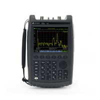
Keysight Technologies FieldFox N9952A User Manual (756 pages)
Brand:
Keysight Technologies
| Category:
Measuring Instruments
| Size: 10.73 MB
Table of Contents
Table of Contents
7
Overview
23
Models and Options
23
Accessories
24
Optional Accessories
24
Fieldfox Manuals, Software, and Supplemental Help
25
Conventions that Are Used in the Manual
25
Safety Notes
25
Preparing for Initial Use of Your New Fieldfox
27
Check the Shipment
27
Meeting Power Requirements for the AC/DC Adapter
27
Install the Lithium-Ion Battery
28
Battery Usage
28
Fieldfox ON/OFF Settings
29
Power Button LED Status
30
Fieldfox High Temperature Protection
30
How to Monitor the Internal Fieldfox Temperature
30
Temperature Control Mode
31
High-Temp Shutdown Warning (RTSA Mode Only)
33
Avoid Overpowering the Fieldfox
34
Take the Fieldfox Tour
35
Front Panel
35
Right Side Panel
38
Top Panel
38
Left Side Panel
40
Screen Tour
41
How to Enter Numeric Values
43
Multiplier Abbreviations
43
Connector Care
44
Cat (Cable and Antenna Test) Mode
45
CAT Mode Settings
47
How to Select CAT Mode
47
Measurement Selection
47
Quick Settings Table
48
Frequency Range
49
Scale Settings
49
Averaging
50
Smoothing
51
Single or Continuous Measure
51
Resolution (Number of Data Points)
52
Sweep Time
52
Output Power
53
Interference Rejection
53
Coupled Frequency
54
1-Port Cable Loss Measurements
55
How to Make a 1-Port Cable Loss Measurement
56
Return Loss Measurements
55
How to Measure Return Loss
55
2-Port Insertion Loss Measurements
57
How to Make Dtf Measurements
60
DTF (Distance to Fault) Measurements How to Make DTF Measurements
60
DTF Measurement Settings
62
DTF Measurement (Format)
62
DTF Settings Table
62
DTF Start and Stop Distance
63
Frequency Mode
63
Coupled Frequency
64
Cable (Correction) Specifications
65
Window Settings
68
About Alias Faults
69
Calculated DTF Values
69
DTF Units
69
TDR (Time Domain Reflectometry) - Option
71
Table of Contents
72
TDR Measurement Settings
74
TDR Measurement (Format)
74
TDR Settings Table
74
TDR Start and Stop Distance
75
TDR Sweep
75
Frequency Mode
76
Cable (Correction) Specifications
77
Window Settings
80
TDR Units
81
Calculated TDR Values
81
About Alias Faults
82
How to Prevent Undersampling
83
Na (Network Analyzer) Mode
85
NA Mode Settings
87
About S-Parameters
87
Mixed-Mode S-Parameters
88
Parameter Conversion
89
Receiver Measurements
90
Multi-Trace Configurations
91
Quick Settings
92
Calibration Settings
93
Format
94
Frequency Range
95
Scale Settings
95
Magnitude Offset
96
Electrical Delay
97
Phase Offset
97
Averaging
98
IF Bandwidth
99
Smoothing
99
Single or Continuous Measure
100
Resolution (Number of Data Points)
100
Sweep Time
101
Triggering
101
Output Power
103
System Impedance (Z0)
104
Port Extensions
104
Velocity Factor
105
Big Marker Display States (a and B)
106
Increase Dynamic Range
108
Time Domain - Option 010
109
Time Domain - Option 010
110
Overview
111
Chapter 6 , “NA (Network Analyzer) Mode”, on Page 85
112
Time Domain (Transform) Settings
112
Start/Stop (Frequency Range) and Points
112
Transform Settings Table
112
Set Frequency Lowpass
113
Start/Stop Time
113
Stimulus (Mode)
113
Distance Units
114
Transform Window
114
Window Layout
114
Line Loss and Velocity Factor
115
Data Chain
116
Trace Settings
117
Gate Enable
117
Transform Enable
117
Gating
118
Gating Type
119
How to Make Time Domain Gating Settings
119
Start, Stop, Center, and Span Gate Times
119
Calibration for Na, Cat, and VVM Modes
121
Chapter 8, "Calibration for NA, CAT, and VVM Modes
121
Calibration for NA, CAT, and VVM Modes
122
Definitions
122
Why and When to Calibrate
122
Calready
123
How to Perform a Calibration
123
Quickcal (N991Xa/2Xa/3Xa Only)
125
Mechanical Cal
127
Ecal
130
Simple Response Cals
132
Calibration Type
134
View Cal
134
Isolation Step
137
Waveguide Calibrations
137
Enhanced Response Optimization
139
Cal on ? - Questionable Accuracy
140
Compatible Mode Calibrations
140
Interpolation
140
Save the Calibration
140
Calready Properties
141
Test the Jumper Cable
142
Verify a Calibration
142
Verifying Calibration and Jumper Cable Integrity
142
Calibration Method Summary
143
SA (Spectrum Analyzer) Mode
145
Table of Contents
146
SA Mode Settings
148
How to Select SA Mode
148
Frequency Range
148
Radio Standard
150
Custom Radio Standards
150
Channel Selection
151
Reverse Swap
153
Scale and Units
153
External Gain
154
Attenuation Control
154
External Gain (SA Chapter) - "External Gain
154
Preamplifier Control (Opt 235)
155
Check for Compressed Measurements
156
Field Strength Measurements
156
Using the Antenna/Cable Editor
158
Source Tracking Offset and Offset Reversal
160
Tune & Listen (AM/FM)
161
Independent Source/Tracking Generator
163
Resolution Bandwidth (Res BW)
165
Video Bandwidth (Video BW)
166
Sweep Type
166
IF Output
167
Sweep Acquisition
169
Very Long Sweep Times
170
Zero Span Measurements
170
Triggering
172
FFT Gating (Opt 238)
175
Single / Continuous / Restart
177
Points
177
Trace Display States (SA Mode)
178
Average Type
179
Average Count
180
Alignments
180
Alignments (SA Chapter) - "Alignments
180
RF Burst Amplitude Alignment
186
Detection Method
188
Display Line
190
Display Lines (SA Chapter) -"Display Line
190
Noise Marker
191
Band/Interval Power Marker
191
Frequency Counter at Marker
192
Time Zero Fixed Marker
193
Audio Beep at Marker Power
193
Meas UNCAL Error
194
Old Data Indicator (*)
194
Channel Measurements
195
Radio Standards and Channel Measurements
195
Measurement Preset
195
Averaging
195
Traces
196
Channel Power (CHP)
196
How to Set up EMF Settings (Requires EMF (Option 358), GPS (Option 307), and SA Mode (Option 233-Mixed Analyzers))
206
EMF Features
207
EMF Setup Procedure
209
Spectrum Emission Mask (SEM) - (SA Mode Only)
218
How to Select Spectrum Emission Mask (SEM) Measurement
220
RTSA (Real-Time Spectrum Analyzer) Mode-Option 350 (CPU2 Only)
225
Table of Contents
226
RTSA Mode Settings
227
How to Select RTSA Mode
227
Frequency Range
227
Scale and Units
228
External Gain
229
Attenuation Control
229
Preamplifier Control (Opt 235)
230
Check for Compressed Measurements
231
Spectrum Selection
231
Resolution Bandwidth (Res BW)
234
Triggering
235
Single / Continuous / Restart / Time Per DIV
238
Acq Time
239
Points (Not User Settable)
239
Trace Display States
240
Detection Method
241
Average Count, Show Density, Blue, and Red Percentage Limits
242
Alignments
243
Display Line
243
Average Count
243
Spectrogram Display
245
Spectrogram Display (RTSA Option)
245
Common Settings for Spectrogram
246
Record/Playback (RTSA Option)
247
About Sessions
247
Fieldfox Setting Changes During Record and Playback
248
About State and User Tags
249
How to Record a Session
250
How to Playback a Session
251
Recording Configuration
252
Record Source
253
Playback Configuration
254
Manage Sessions
254
Record Playback Example (RTSA Mode Only)
255
IQ Analyzer (IQA) - Option 351 (CPU2 Only)
257
Display Lines (Sa Chapter) -"Display Line
258
About I/Q Analyzer (IQA) Measurements
260
I/Q Analyzer (IQA) Mode Settings
261
How to Make Measurements Using the I/Q Analyzer Mode
261
How to Capture I/Q Data to a File
262
How to Modify the I/Q Data Measurement Parameters
265
Adjusting the Bandwidth Settings
265
Changing between the Continuous and Single Captures and Adjusting the Trigger Settings
268
Adjusting the Measurement Setup Settings
270
Adjusting the Trace Settings
271
Adjusting the Frequency Settings
272
Adjusting the Scale and Amplitude Settings
273
Preamplifier Control (Opt 235)
275
Using Markers (IQA)
276
Noise Marker
276
Band/Interval Power Marker
277
Band Span Marker (Spectrum Only)
278
Interval Span Marker (Waveform Only)
278
Coupled Markers (Waveform Only)
278
Continuous Peak Search Marker
280
Alignments
281
Trace Display States (IQA Mode)
281
How to Display the Trace States
281
Other Features Available
283
Alignments (Sa Chapter) - "Alignments
286
Using OTA (Options 370 - LTE FDD and 377 - 5GTF)
287
About Over-The-Air (OTA) Measurements
288
LTE FDD Features (Option 370)
288
5GTF Features (Option 377)
292
How to Set up Over-The-Air (OTA) Mode Settings
294
OTA Setup Procedure
294
Optional: Using RTSA to Verify the Signal Quality
294
Optional: Using RTSA to Verify the Signal Quality
304
And Preamp Option 235)
304
- "Step 2: Select Trace Type" on Page 308
305
How to Define a Cell or Cell(S) and Use OTA
305
Step 2: Select Trace Type
308
Step 3. Modify Scale and the Display Color Bar Settings
309
Step 4: Enable Recording and Record Data Logging Results
310
Save 5: Save the Log Results
312
Step 6: Import and Play Back KML Files into 3Rd Party Software (Example: Google Earth with Animation Tool)
313
How to Set up EMF Settings (Requires EMF (Option 358))
315
EMF Features
315
EMF Setup Procedure
318
How to Use Data Logging (OTA Options 370 and 377)
322
Screen Annotation
322
Data Logging Procedure
323
To Change Recording Configuration Settings
323
How to Playback
324
Other Features Available
325
Troubleshooting
326
Glossary (OTA)
327
Using the Phased Array Antenna (Option 360)
331
About Phased Array Antenna Measurements
332
Phased Array Antenna Features (Option 360)
332
How to Set up Phased Array Antenna Settings
341
Option 360 Setup Procedure
341
- "Step 1. Connect Your Equipment" on Page
352
How to Define a Set up a Scan and Use Option 360
352
Step 1. Connect Your Equipment
352
Step 2. Set Fieldfox to Use Static IP with Your Ball Antenna
352
Step 3. Define the Measurement
353
Step 4: Select Polar Settings
355
Step 5. Modify Scale and Attenuator Settings
355
Step 6: Enable Recording and Record Data Logging Results
356
Step 7: Import and Play Back KML Files into 3Rd Party Software (Example: Google Earth with Animation Tool)
358
How to Record/Playback (Option 360)
359
Screen Annotation
359
G Rapid Prototype Phased Array Antenna - Option
360
How to Record
360
To Change Recording Configuration Settings
361
How to Playback
361
Other Features Available
363
Troubleshooting
364
USB Antennas - (Full Capability Requires EMF Option 358, and SA Mode (Option 233 Mixed Analyzers))
365
Using USB Antennas
368
About USB Antenna Measurements
369
USB Antenna Features
369
How to Set up a USB Antenna
371
USB Antenna Setup Procedure
371
Other Features Available
375
Troubleshooting
376
On-The-Box Mapping - Option 352 (Requires Spectrum Analyzer Mode (Option 233 on N991Xb), GPS (Option 307) and GPS Receiver (Option 307))
377
How to Install Node.js and Running the Fieldfox Mapping Software
382
Downloading and Using the Fieldfox Map Support Tool
384
Importing a .Zip File to the Fieldfox
388
How to Set up Mapping Settings
390
How to Set up Mapping When the Fieldfox Is on the LAN
390
Option 352 Indoor Maps Setup Procedure
392
Option 352 Outdoor Maps Setup Procedure
395
Setting up Data Logging
403
How to Record/Playback (Option 352)
405
Screen Annotation
405
How to Record
406
How to Playback
407
To Change Recording Configuration Settings
407
Other Features Available
409
Troubleshooting
410
Remote Server Mode (Requires CPU2 and SA Hardware/Sa Option 233) in this Chapter
415
Connecting Using Remote Server
416
Changing Frequency Converter Head Settings
417
89600 VSA Software Overview (Requires CPU2 and N991Xa/3X/A5X/A6Xa and SA Option 233)
418
Spectrogram and Waterfall Displays
422
Spectrogram Display (SA Option)
422
Common Settings for Waterfall and Spectrogram
424
Waterfall Display
425
Record/Playback (SA Option)
427
About Sessions
427
Fieldfox Setting Changes During Record and Playback
428
About State and User Tags
429
How to Record a Session
430
How to Playback a Session
431
Recording Configuration
431
Frequency Mask Trigger Configuration (SA Mode Only)
433
Record Source
434
Manage Sessions
435
Playback Configuration
435
Record Playback Example (SA Only)
436
Reflection Mode (SA Models) - Option
439
Reflection Mode Settings
442
How to Select Reflection Mode
442
Measurement Selection
442
Normalize
442
Built-In Power Meter Mode - Option
445
Built-In Power Meter Settings
447
Frequency/ Span / Step
447
How to Select Built-In Power Meter Mode
447
Attenuation
448
Power Meter (USB) Mode - Option
449
Supported Power Sensors
451
How to Connect the Power Sensor
451
USB Power Meter Settings
453
Average / Peak
453
How to Select Power Meter Mode
453
Zeroing
453
Frequency
454
Source Control
454
Display Units
456
Relative and Offset Power Measurements
456
Resolution
456
Averaging
457
Single or Continuous Measure
457
Limits
458
Step Detection Mode
458
21 Frequency Offset Using Power Sensor (FOPS) - Option
459
Overview
461
FOPS Settings
463
How to Select Power Meter (USB Sensor)
463
Measurement Selection
463
Sweep Type and Frequency
464
Power Sensor Settling
466
Sweep Settings
466
Amplitude Markers
467
Trace Math
467
Pulse Measurements Mode - Option
469
Supported Power Sensors
471
How to Connect the Power Sensor
471
Switching between Pulse Measurement Mode and Power Meter Mode
471
Pulse Measurement Settings
472
Frequency / Time
472
How to Select Pulse Measurement Mode
472
Measurement Selection
472
Zoom Window
473
Averaging
474
Scale
474
Single or Continuous Measure
475
Video Bandwidth
475
Resolution
476
Triggering
476
Marker Settings
479
Amplitude Markers
480
Marker Search
480
Auto Analysis
481
Grid
482
Pulse Top
482
Trace Memory
483
Overview
487
VVM Mode Settings
488
Display Resolution
488
Frequency Selection
488
How to Select VVM Mode
488
Measurement Selection
488
IF Bandwidth
489
Output Power
489
Averaging
490
Single or Continuous Measure
491
VVM Calibration
491
Zeroing
491
1-Port Cable Trimming Measurements
493
How to Make a 1-Port Cable Trimming Measurement
493
2-Port Transmission Measurements
495
How to Make a 2-Port Transmission Measurement
495
A/B and B/A Measurements
497
Erta (Extended Range Transmission Analysis) Mode - Option 209
499
Overview
500
Requirements and Limitations
501
Limitations
501
Requirements
501
Start Connection Wizard
502
On the Receiver Unit
502
Configure Measurement Settings
506
Select Measurement
506
Normalize
507
Source Tracking Offset and Offset Reversal
507
Improve Dynamic Range
508
Source Enable and Source Mode
508
AM/FM Metrics (SA Only and Option 355)
509
Overview of Measurement Types
509
Using AM/FM Metrics
509
How to Set up AM/FM Metrics
512
SINAD and THD Calculations
516
Interpreting AM/FM Metrics Error Messages
519
Test Tone Not Found
519
Channel Scanner (Option 312)
523
Using Channel Scanners
523
How to Set up Channel Scanner
524
How to Define a Channel and Use Channel Scanner
526
Field Strength Measurements
538
Using the Antenna/Cable Editor
544
Noise Figure Mode (Option 356 - CPU2 Only)
547
Using Noise Figure
550
Example: Typical Noise Figure Measurement Procedure
554
How to Define a Noise Figure Measurement
554
Overview of Softkey Menus
555
How to Use DUT Measurement Setups
562
Points
574
Single / Continuous / Restart
574
Alignments
575
Resolution Bandwidth (Res BW)
575
Calculating Noise Figure Measurement Uncertainty
576
Using ENR Tables
581
About ENR (*.Enr), Preamplifier (*.Amp), and DUT (*.Dut) Files
582
Using Markers (Noise Figure)
584
Calibration Wizard
585
When to Calibrate
585
About Auto-Integration
588
How to Use Auto-Integration
588
Auto-Integration Procedure
589
Other Features Available
594
Troubleshooting
595
28 Data Analysis Features
597
All about Markers
598
How to Create Markers
598
How to Move a Marker after It Is Created
598
About Delta Markers
599
Marker Table
600
Signal Track Marker (NF and SA Mode ONLY)
600
Coupled Markers (NA Mode)
601
Marker Colors
602
Marker Trace (CAT, NA, NF Modes)
602
Marker Trace (IQA and SA Mode)
602
Marker Format
603
Searching with Markers
604
What Is a 'Peak
609
Marker Functions
611
I/Q Analyzer (IQA) Marker Functions
612
SA Marker Functions
612
All about Limit Lines
613
How to Create Fixed Limit Lines
613
Limit Lines (Data Analysis Chapter) - "All about Limit Lines
613
Build from Trace
614
Relative Limit Lines
614
Limit Options
615
How to Save and Recall Limits
616
Display Line (I/Q, NF, and SA Modes Only)
617
All about Trace Math
618
How to Display Data and Memory Traces
618
How to Perform Trace Math
618
About Math Operations
619
All about Scale Settings
620
How to Use Scale Settings
620
Averaging (CAT, NA, Power Meter, Channel Scanner, and Pulse Measurement Modes Only)
621
Chapter 29 System Settings
624
Run/Hold
624
How to Perform a Single Sweep While in Hold
624
Preset
625
How to Preset the Fieldfox
625
User Preset
625
How to Recall User Preset
626
How to Set User Preset
626
Audio (Volume) Control
626
How to Set the Fieldfox Volume Control
627
Display (Settings)
627
Display Brightness
627
Display Colors
627
Title
628
Trace Width
628
Edit Keywords
629
Full Screen Mode
629
Utilities
630
How to View and Change Utilities Settings
630
Preferences
637
Quick Settings Table
637
Global Settings (Overview)
639
Save and Reset Preferences
639
Display
641
Audio
642
Date and Time
643
GPS - Distance Settings
643
How to Select CAT Distance Units
643
File Folders
644
How to Set File Folders
644
Alpha Numeric Editing
645
File Saving Naming Options
645
CAT (Distance Units)
645
Cat/Na
647
Discrete Colors Softkey Menu
649
Using the Discrete Colors Softkey Menu
649
System Configuration
649
Options (Licensing)
649
GNSS (GPS+) and GPS
650
Frequency Reference Source
654
Variable Voltage Source (Opt. 309)
656
Security Level
657
Date and Time, Format, and Time Zone Settings
658
LAN Settings
659
Fieldfox Package Installer
661
Power on
661
Serial Number Prefixes ≥5607)
661
Service Diagnostics
663
System Information
663
Using the Mini-USB Port to Send SCPI Commands and Queries
669
Mini-USB Connection to PC with IO Libraries
669
Chapter 31 31 File Management
671
Saving and Recalling Files
672
Save Files
672
Move (Copy) Files
676
Recall Files
676
Set File Type and Select Device
677
Manage Files
680
Manage Folders
682
Edit Keywords
683
Prefixes and Suffixes for Filenames
683
Press Printing
686
How to Print the Current Screen or a Saved File
686
32 Working with the Lithium-Ion Battery
687
Viewing the Battery Charge Status
687
Built-In Battery Gauge
688
Service Diagnostics-Battery Screen
688
Charging the Battery
689
Internal Charging with the AC/DC Adapter
689
Using the External Battery Charger (N9910X-872)
691
Battery Care
692
Maximizing Battery Life
692
Reconditioning Battery
692
Lithium-Ion Battery Disposal
693
33 Safety Considerations
695
For the Fieldfox
696
For the AC/DC Adapter
698
For the Battery
699
For the External Battery Charger (N9910X-872)
699
High Capacity Lithium Battery (N9910X-876)
699
Standard Capacity Battery (N9910X-870)
701
Battery Protective Functions
703
Battery Protective Functions (N9910X-876)
703
Battery Protective Functions (N9910X-870)
705
Batteries: Safe Handling and Disposal
706
Battery Transportation
706
Electrical Requirements
707
Electrostatic Discharge (ESD) Precautions
707
Environmental Requirements
707
Fieldfox Markings
708
Battery Markings
709
AC/DC Adapter Markings
711
Packaging Markings
711
Certification
712
Certification and Compliance Statements
712
Declaration of Conformity
712
Manufacturer's Declaration
712
Acoustic Statement (European Machinery Directive)
713
Emc
713
Safety
713
South Korean Class B EMC Declaration
713
A:.connector Care Review
715
B:.specifications/Data Sheet
717
C:.instrument Calibration
719
How Do I Get an Instrument Calibration
719
How Often Should Calibrate My Instrument
719
What Are My Choices of Instrument Calibration
720
D:.korean Battery Safety Translation
721
Advertisement
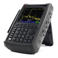
Keysight Technologies FieldFox N9952A Service Manual (179 pages)
Handheld Analyzers
Brand:
Keysight Technologies
| Category:
Measuring Instruments
| Size: 5.83 MB
Table of Contents
Table of Contents
5
1 Safety and Regulatory Information
9
Information in this Chapter
9
Safety Symbols
10
General Safety Considerations
10
Safety Earth Ground
10
Before Applying Power
11
Servicing
11
Electrostatic Discharge Protection
12
Regulatory Information
14
Instrument Markings
14
Battery Disposal
15
2 General Product Information
17
Information in this Chapter
17
Documentation Map
18
Maintenance
19
Physical Maintenance
19
Electrical Maintenance
19
Fieldfox Models
19
Fieldfox Options
20
Option Descriptions
22
Keysight Support, Services, and Assistance
27
Service and Support Options
27
Calibration Options
27
Contacting Keysight
28
Shipping Your Analyzer to Keysight for Service or Repair
28
3 Tests and Adjustments
29
Information in this Chapter
29
Before You Begin
30
Protect against Electrostatic Discharge (ESD)
30
Allow the Analyzer to Warm up
30
Review the Principles of Connector Care
30
Service Test Equipment
32
Before Returning an Instrument to a Customer
33
Operational Check
34
Required Equipment
34
Procedure
34
Performance Tests (Keysight N7841A Software Package)
36
Performance Verification Tests
37
Adjustments (Keysight N7841A Software Package)
38
Adjustments
38
4 Troubleshooting
39
Information in this Chapter
39
Protect against Electrostatic Discharge (ESD)
40
Assembly Replacement Sequence
40
Fieldfox High-Temperature Protection
41
How to Monitor the Internal Fieldfox Temperature
41
Temperature Control Mode
41
High-Temp Shut down
41
Getting Started with Troubleshooting
42
Check the Basics
42
Troubleshooting Organization
43
Power up Troubleshooting
44
Front Panel Group Troubleshooting
45
Checking Display Brightness and Sound
45
Checking the Front Panel Keys
45
USB and SD Card Slot Ports
46
Measurement Group Troubleshooting
47
Problems in NA Mode
47
Problems in SA Mode
49
5 Theory of Operation
53
Information in this Chapter
53
Analyzer System Operation
54
Functional Groups of the Analyzer
54
Front Panel Group
56
A3 Front Panel Interface Board
56
A2 LCD Assembly
57
Measurement Group
58
A4 RF Board
58
A5 System Board
66
A6 SOM Board
70
A7 Real Time Clock Board
71
Main Battery
71
Grounding and Power
72
Grounding
72
Voltages and Power Supplies
73
Power Control and Management
74
Battery Related Information
76
Operation in Modes
78
CAT, NA, and VVM Modes
80
SA and CPM Mode
80
Power Meter Mode
81
Temperature Related Information
82
User Calibration in CAT, NA, and VVM Modes
83
Factory Calibration (Calready)
83
Quickcal - N991Xa, N992Xa, N993Xa Only
84
Mechanical Calibration
84
Firmware Related Information
85
General Description
85
User Accessible Files
85
Operational Files
85
Erase User Data Utility
85
Error Log
86
Firmware Upgrades
86
LAN Interface
87
LAN Leds (N995Xa and N996Xa Only)
87
6 Replaceable Parts
89
Information in this Chapter
89
Ordering Information
90
Assembly Replacement Procedure
91
Replaceable Parts Listings
92
Entire Analyzer
92
Front Panel Group
93
Measurement Group
95
Case Group
100
Miscellaneous Parts
103
7 Repair and Replacement Procedures
105
Information in this Chapter
105
Personal Safety Warnings
106
Safety Earth Ground
106
Electrostatic Discharge (ESD) Protection
106
Assembly Replacement Sequence
107
Removal and Replacement Procedures
108
Removing and Replacing the Main Battery
109
Removing and Replacing the Case Group Parts
111
Removing and Replacing the Front Panel Group Assemblies
130
Removing and Replacing the Measurement Group Assemblies
136
Final Assembly Procedure
164
Post-Repair Procedures
165
Manual Checks and Procedures
166
Processor Upgrade Procedures
167
8 General Purpose Maintenance and Service Procedures
169
Information in this Chapter
169
Service Related User Operations
170
To View Currently Installed Options
170
To View the Current Firmware Revision, Etc
170
To View the Error Log
170
To View Temperature Readings
171
Erase User Data Utility
171
Options
172
To View Currently Installed Options
172
Re-Installing Options
172
Firmware Upgrades
174
To Check the Current Firmware Revision
174
Miscellaneous Service and Maintenance
174
Cleaning the Display
174
Battery Maintenance
174
Keysight Technologies FieldFox N9952A Configuration Manual (21 pages)
Handheld Analyzers 4/6.5/9/14/18/26.5/32/44/50 GHz
Brand:
Keysight Technologies
| Category:
Measuring Instruments
| Size: 2.52 MB
Table of Contents
Table of Contents
2
The Fieldfox Handheld Analyzer Family
3
Fieldfox RF and Microwave (Combination) Analyzers
4
Fieldfox RF and Microwave (Combination) Analyzer Faqs
5
Faqs - Applicable to All Fieldfox RF and Microwave Analyzers
8
Fieldfox Microwave Vector Network Analyzers
10
Fieldfox Microwave Vector Network Analyzer Faqs
11
Fieldfox Microwave Spectrum Analyzers
12
Fieldfox Spectrum Analyzer Faqs
13
Documentation
13
Upgrades
14
Calibration Kits
16
Accessories
18
Advertisement
Advertisement
Related Products
Keysight Technologies FieldFox N9950A
Keysight Technologies FieldFox N9951A
Keysight Technologies FieldFox N9950B
Keysight Technologies FieldFox N9951B
Keysight Technologies FieldFox N9952B
Keysight Technologies FieldFox N9953B
Keysight Technologies FieldFox N9912A
Keysight Technologies FieldFox N9923A
Keysight Technologies N9935C
Keysight Technologies FieldFox N9913A
Keysight Technologies Categories
Measuring Instruments
Test Equipment
Control Unit
Portable Generator
Power Supply
More Keysight Technologies Manuals
Login
Sign In
OR
Sign in with Facebook
Sign in with Google
Upload manual
Upload from disk
Upload from URL