Sign In
Upload
Manuals
Brands
Juniper Manuals
Network Router
XRE200 -
Juniper XRE200 - Manuals
Manuals and User Guides for Juniper XRE200 -. We have
3
Juniper XRE200 - manuals available for free PDF download: Hardware Manual, Datasheet
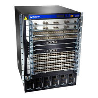
Juniper XRE200 - Hardware Manual (354 pages)
Junos OSfor EXSeries EthernetSwitches
Brand:
Juniper
| Category:
Switch
| Size: 3 MB
Table of Contents
Table of Contents
3
About the Documentation
15
Documentation and Release Notes
15
Supported Platforms
15
Using the Examples in this Manual
15
Merging a Full Example
16
Merging a Snippet
16
Documentation Conventions
17
About the Documentation
17
Table 1: Notice Icons
17
Table 2: Text and Syntax Conventions
17
Documentation Feedback
19
Requesting Technical Support
19
Self-Help Online Tools and Resources
19
Opening a Case with JTAC
20
Overview
21
Interfaces Overview
21
Chapter 1 Interfaces Overview
23
Interfaces Overview
23
EX Series Switches Interfaces Overview
23
Network Interfaces
23
Special Interfaces
24
Table 3: Network Interface Types and Purposes
24
Table 4: Special Interface Types and Purposes
24
Understanding Interface Naming Conventions on EX Series Switches
26
Physical Part of an Interface Name
26
Logical Part of an Interface Name
28
Wildcard Characters in Interface Names
28
Understanding Aggregated Ethernet Interfaces and LACP
28
Link Aggregation Group (LAG)
29
Table 5: Maximum Interfaces Per LAG and Maximum Lags Per Switch
29
Link Aggregation Control Protocol (LACP)
30
ECMP Traffic
31
Understanding the Hashing Algorithm
31
IP (Ipv4 and Ipv6)
32
Table 6: Ipv4 and Ipv6 Hashing Fields
33
Mpls
34
Table 7: MPLS Hashing Fields
34
MAC-In-MAC Packet Hashing
35
Layer 2 Header Hashing
35
Table 8: MAC-In-MAC Hashing Fields
35
Table 9: Layer 2 Header Hashing Fields
35
Understanding How Energy Efficient Ethernet Reduces Power Consumption on
36
Interfaces
36
Understanding Local Link Bias
36
Figure 1: Egress Traffic Flow with Local Link Bias
37
Figure 2: Egress Traffic Flow Without Local Link Bias
37
Understanding Layer 3 Subinterfaces
38
Understanding Unicast RPF
39
Unicast RPF for Switches Overview
39
Unicast RPF Implementation
40
Unicast RPF Packet Filtering
40
Bootstrap Protocol (BOOTP) and DHCP Requests
40
Default Route Handling
40
When to Enable Unicast RPF
40
When Not to Enable Unicast RPF
41
Figure 3: Symmetrically Routed Interfaces
41
Limitations of the Unicast RPF Implementation on EX3200, EX4200, and EX4300 Switches
42
Figure 4: Asymmetrically Routed Interfaces
42
Understanding IP Directed Broadcast for EX Series Switches
43
IP Directed Broadcast for EX Series Switches Overview
43
IP Directed Broadcast Implementation for EX Series Switches
43
When to Enable IP Directed Broadcast
44
When Not to Enable IP Directed Broadcast
44
Understanding Interface Ranges on EX Series Switches
44
802.1Q Vlans Overview
46
Configuration
49
Part 2 Configuration
49
Chapter 2 Configuration Tasks
51
Configuring Gigabit Ethernet Interfaces (CLI Procedure)
52
Configuring VLAN Options and Interface Mode
52
Configuring the Link Settings
53
Configuration Tasks
53
Table 10: Factory Default Configuration Link Settings for EX Series Switches
53
Configuring the IP Options
54
Configuring Gigabit Ethernet Interfaces (J-Web Procedure)
55
Table 11: Port Edit Options
57
Table 12: Recommended Cos Settings for Port Roles
60
Port Role Configuration with the J-Web Interface (with CLI References)
61
Table 13: Port Role Configuration Summary
61
Table 14: Recommended Cos Settings for Port Roles
64
Adding a Logical Unit Description to the Configuration
65
Disabling a Physical Interface
65
Example: Disabling a Physical Interface
66
Disabling a Logical Interface
67
Configuring Flow Control
67
Configuring the Interface Address
68
Configuring Interface Ipv4 Addresses
69
Operational Behavior of Interfaces When the same Ipv4 Address Is Assigned to Them
70
Configuring Interface Ipv6 Addresses
71
Configuring the Interface Bandwidth
72
Configuring the Media MTU
73
Media MTU Overview
74
How to Configure the Media MTU
75
Encapsulation Overhead by Encapsulation Type
76
Table 15: Encapsulation Overhead by Encapsulation Type
76
Media MTU Sizes by Interface Type for M5 and M7I Routers with CFEB, M10 and M10I Routers with CFEB, and M20 and M40 Routers
77
Media MTU Sizes by Interface Type for M40E Routers
77
Table 16: Media MTU Sizes by Interface Type for M5 and M7I Routers with CFEB, M10 and M10I Routers with CFEB, and M20 and M40 Routers
77
Table 17: Media MTU Sizes by Interface Type for M40E Routers
77
Media MTU Sizes by Interface Type for M160 Routers
79
Media MTU Sizes by Interface Type for M7I Routers with CFEB-E, M10I Routers with CFEB-E, and M320 and M120 Routers
79
Table 18: Media MTU Sizes by Interface Type for M160 Routers
79
Table 19: Media MTU Sizes by Interface Type for M7I Routers with CFEB-E, M10I Routers with CFEB-E, and M320 and M120 Routers
79
Media MTU Sizes by Interface Type for MX Series Routers
80
Table 20: Media MTU Sizes by Interface Type for MX Series Routers
80
Media MTU Sizes by Interface Type for T320 Routers
81
Media MTU Sizes by Interface Type for T640 Platforms
81
Table 21: Media MTU Sizes by Interface Type for T320 Routers
81
Table 22: Media MTU Sizes by Interface Type for T640 Platforms
81
Media MTU Sizes by Interface Type for J2300 Platforms
82
Media MTU Sizes by Interface Type for J4300 and J6300 Platforms
82
Table 23: Media MTU Sizes by Interface Type for J2300 Platforms
82
Table 24: Media MTU Sizes by Interface Type for J4300 and J6300
82
Media MTU Sizes by Interface Type for J4350 and J6350 Platforms
83
Table 25: Media MTU Sizes by Interface Type for J4350 and J6350
83
Media MTU Sizes by Interface Type for EX Series Switches and ACX Series Routers
85
Media MTU Sizes by Interface Type for PTX Series Packet Transport Routers
85
Setting the Protocol MTU
85
Table 26: Media MTU Sizes by Interface Type for EX Series Switches and ACX
85
Table 27: Media MTU Sizes by Interface Type for PTX Series Packet Transport
85
Interface Ranges
86
Configuring Interface Ranges
87
Expanding Interface Range Member and Member Range Statements
89
Configuration Inheritance for Member Interfaces
90
Member Interfaces Inheriting Configuration from Configuration Groups
91
Interfaces Inheriting Common Configuration
93
Configuring Inheritance Range Priorities
93
Configuration Expansion Where Interface Range Is Used
93
Configuring Accounting for the Physical Interface
94
Applying an Accounting Profile to the Physical Interface
95
Example: Applying an Accounting Profile to the Physical Interface
95
Configuring Accounting for the Logical Interface
96
Applying an Accounting Profile to the Logical Interface
96
Example: Applying an Accounting Profile to the Logical Interface
96
Configuring Ethernet Loopback Capability
97
Configuring Gratuitous ARP
98
Configuring Static ARP Table Entries
99
Example: Configuring Static ARP Table Entries
99
Disabling the Transmission of Redirect Messages on an Interface
100
Configuring Restricted and Unrestricted Proxy ARP
100
Enabling or Disabling SNMP Notifications on Logical Interfaces
101
Configuring Aggregated Ethernet Links (CLI Procedure)
102
Configuring Aggregated Ethernet Interfaces (J-Web Procedure)
103
Table 28: Aggregated Ethernet Interface Options
104
Table 29: VLAN Options
105
Table 30: IP Options
105
Configuring Aggregated Ethernet LACP (CLI Procedure)
106
Configuring LACP Link Protection of Aggregated Ethernet Interfaces
107
Procedure)
108
Configuring LACP Link Protection at the Global Level
108
Configuring LACP Link Protection at the Aggregated Interface Level
108
Configuring Aggregated Ethernet Link Protection
109
Configuring Link Protection for Aggregated Ethernet Interfaces
109
Configuring Primary and Backup Links for Link Aggregated Ethernet
109
Interfaces
109
Reverting Traffic to a Primary Link When Traffic Is Passing through a Backup Link
110
Disabling Link Protection for Aggregated Ethernet Interfaces
110
Configuring Aggregated Ethernet Link Speed
110
Configuring Aggregated Ethernet Minimum Links
112
Configuring Energy Efficient Ethernet on Interfaces (CLI Procedure)
113
Enabling EEE on an EEE-Capable Base-T Copper Ethernet Port
113
Disabling EEE on a Base-T Copper Ethernet Port
113
Configuring Local Link Bias (CLI Procedure)
114
Configuring the Fields in the Algorithm Used to Hash LAG Bundle and ECMP Traffic (CLI Procedure)
114
Configuring the Hashing Algorithm to Use Fields in the Layer 2 Header for Hashing
115
Hashing
115
Hashing
116
Configuring Tagged Aggregated Ethernet Interfaces
116
Configuring a Layer 3 Subinterface (CLI Procedure)
117
Configuring Unicast RPF (CLI Procedure)
117
Disabling Unicast RPF (CLI Procedure)
119
Configuring IP Directed Broadcast (CLI Procedure)
120
Tracing Operations of an Individual Router or Switch Interface
121
Tracing Operations of the Interface Process
121
Configuration Tasks
51
Chapter 3 Configuration Statements
123
[Edit Chassis] Configuration Statement Hierarchy on EX Series Switches
125
Supported Statements in the [Edit Chassis] Hierarchy Level
125
Level
126
Switches
127
Unsupported Subhierarchies in the [Edit Forwarding-Options] Hierarchy
127
Level
127
Table 31: Unsupported [Edit Forwarding-Options] Subhierarchies on EX Series
127
[Edit Interfaces] Configuration Statement Hierarchy on EX Series Switches
128
Supported Statements in the [Edit Interfaces Ae] Hierarchy Level
129
Unsupported Statements in the [Edit Interfaces Ae] Hierarchy Level
133
Table 32: Unsupported [Edit Interfaces Ae] Configuration Statements for EX
133
[Edit Interfaces Et] Configuration Statement Hierarchy on EX Series
134
Switches
134
Supported Statements in the [Edit Interfaces Et] Hierarchy Level
134
Unsupported Statements in the [Edit Interfaces Et] Hierarchy Level
138
Table 33: Unsupported [Edit Interfaces Et] Configuration Statements for EX
138
[Edit Interfaces Ge] Configuration Statement Hierarchy on EX Series
139
Switches
139
Supported Statements in the [Edit Interfaces Ge] Hierarchy Level
140
Unsupported Statements in the [Edit Interfaces Ge] Hierarchy Level
144
Table 34: Unsupported [Edit Interfaces Ge] Configuration Statements for EX
144
[Edit Interfaces Interface-Range] Configuration Statement Hierarchy on EX Series
145
Switches
145
Supported Statements in the [Edit Interfaces Interface-Range] Hierarchy
146
Level
146
Unsupported Statements in the [Edit Interfaces Interface-Range] Hierarchy
146
Table 35: Unsupported [Edit Interfaces Interface-Range] Configuration
149
Switches
154
Supported Statements in the [Edit Interfaces Irb] Hierarchy Level
154
Unsupported Statements in the [Edit Interfaces Irb] Hierarchy Level
157
[Edit Interfaces Lo] Configuration Statement Hierarchy on EX Series
157
Switches
157
Table 36: Unsupported [Edit Interfaces Irb] Configuration Statements for EX
157
Supported Statements in the [Edit Interfaces Lo] Hierarchy Level
158
Unsupported Statements in the [Edit Interfaces Lo] Hierarchy Level
160
[Edit Interfaces Me] Configuration Statement Hierarchy on EX Series
160
Switches
160
Table 37: Unsupported [Edit Interfaces Lo] Configuration Statements for EX
160
Supported Statements in the [Edit Interfaces Me] Hierarchy Level
161
Unsupported Statements in the [Edit Interfaces Me] Hierarchy Level
163
Table 38: Unsupported [Edit Interfaces Me] Configuration Statements for EX
163
[Edit Interfaces Vme] Configuration Statement Hierarchy on EX Series
164
Switches
164
Supported Statements in the [Edit Interfaces Vme] Hierarchy Level
164
Unsupported Statements in the [Edit Interfaces Vme] Hierarchy Level
167
[Edit Interfaces Xe] Configuration Statement Hierarchy on EX Series
167
Switches
167
Supported Statements in the [Edit Interfaces Xe] Hierarchy Level
167
Unsupported Statements in the [Edit Interfaces Xe] Hierarchy Level
171
Table 39: Unsupported [Edit Interfaces Xe] Configuration Statements for EX
171
Switches
172
Supported Statements in the [Edit Protocols Lacp] Hierarchy Level
173
Unsupported Statements in the [Edit Protocols Lacp] Hierarchy Level
173
Accounting-Profile
175
Address
176
Aggregated-Devices
178
Aggregated-Ether-Options
179
Arp (Interfaces)
180
Auto-Negotiation
181
Bandwidth (Interfaces)
183
Broadcast
184
Chassis
185
Description (Interfaces)
186
Device-Count
187
Disable (Interface)
188
Enhanced-Hash-Key
190
Ether-Options
192
Ethernet (Aggregated Devices)
193
Eui-64
193
Family
194
Table 40: Protocol Families and Supported Interface Types
198
Filter
200
Flow-Control
201
Force-Up
202
Gratuitous-Arp-Reply
202
Hash-Mode
203
Hold-Time (Physical Interface)
205
Ieee-802-3Az-Eee
206
Inet (Enhanced-Hash-Key)
207
Inet6 (Enhanced-Hash-Key)
209
Interface (Multichassis Protection)
210
Interface-Mode
211
Interface-Range
213
Lacp (Aggregated Ethernet)
215
Lacp (802.3Ad)
217
Layer2 (Enhanced-Hash-Key)
218
Link-Mode
220
Link-Protection
222
Link-Speed (Aggregated Ethernet)
223
Local-Bias
224
Loopback (Aggregated Ethernet, Fast Ethernet, and Gigabit Ethernet)
225
Member (Interface Ranges)
226
Member-Range
227
Members
228
Mtu
230
Native-Vlan-ID
233
No-Gratuitous-Arp-Request
234
No-Redirects
234
Periodic
235
Preferred
236
Primary (Address on Interface)
237
Proxy-Arp
238
Rpf-Check
239
Speed (Ethernet)
240
Traceoptions (Individual Interfaces)
241
Traceoptions (Interface Process)
243
Transmit-Interval (Liveness Detection)
244
Traps
245
Unit
246
Vlan (802.1Q Tagging)
247
Vlan-ID (VLAN Tagging and Layer 3 Subinterfaces)
248
Vlan-Tagging
249
Configuration Statements
123
Administration
251
Part 3 Administration
251
Chapter 4 Routine Monitoring
253
Verifying the Status of a LAG Interface
254
Verifying that EEE Is Saving Energy on Configured Ports
255
Verifying that LACP Is Configured Correctly and Bundle Members Are Exchanging LACP Protocol Packets
257
Verifying the LACP Setup
257
Verifying that LACP Packets Are Being Exchanged
257
Verifying that Layer 3 Subinterfaces Are Working
258
Verifying Unicast RPF Status
259
Verifying IP Directed Broadcast Status
261
Routine Monitoring
253
Monitoring Interface Status and Traffic
253
Chapter 5 Operational Commands
263
Monitor Interface
264
Table 41: Output Control Keys for the Monitor Interface Command
264
Table 42: Output Control Keys for the Monitor Interface Traffic Command
265
Table 43: Monitor Interface Output Fields
266
Request Diagnostics Tdr
272
Table 44: Request Diagnostics Tdr Output Fields
273
Show Diagnostics Tdr
274
Table 45: Show Diagnostics Tdr Output Fields
275
Show Forwarding-Options Enhanced-Hash-Key
279
Table 46: Show Forwarding-Options Enhanced-Hash-Key Output Fields
279
Show Interfaces Diagnostics Optics
282
Table 47: Show Interfaces Diagnostics Optics Output Fields
282
Show Interfaces Ge
296
Table 48: Show Interfaces Ge- Output Fields
297
Show Interfaces Irb
308
Table 49: Show Interfaces Irb Output Fields
308
Show Interfaces Me0
314
Table 50: Show Interfaces Me0 Output Fields
314
Show Interfaces Queue
321
Table 51: Show Interfaces Queue Output Fields
321
Show Interfaces Xe
327
Table 52: Show Interfaces Xe- Output Fields
328
Show Lacp Interfaces
341
Table 53: Show Lacp Interfaces Output Fields
342
Test Interface Restart-Auto-Negotiation
346
Operational Commands
263
Part 4 Troubleshooting
347
Troubleshooting
347
Chapter 6 Troubleshooting Procedures
349
Ipv6 Interface Traffic Statistics Are Not Supported
350
Troubleshooting Interface Configuration and Cable Faults
350
Interface Configuration or Connectivity Is Not Working
350
Troubleshooting Unicast RPF
351
Legitimate Packets Are Discarded
351
Diagnosing a Faulty Twisted-Pair Cable (CLI Procedure)
352
Troubleshooting Procedures
349
Troubleshooting an Aggregated Ethernet Interface
349
Show Interfaces Command Shows the LAG Is down
349
Logical Interface Statistics Do Not Reflect All Traffic
349
Advertisement
Juniper XRE200 - Hardware Manual (188 pages)
External Routing Engine
Brand:
Juniper
| Category:
Network Hardware
| Size: 3 MB
Table of Contents
Table of Contents
3
About the Documentation
9
Documentation and Release Notes
9
Using the Examples in this Manual
9
Merging a Full Example
10
Merging a Snippet
11
Documentation Conventions
11
Documentation Feedback
14
Requesting Technical Support
14
Self-Help Online Tools and Resources
15
Creating a Service Request with JTAC
15
Overview
16
XRE200 System Overview
17
XRE200 External Routing Engine Hardware Overview
17
Benefits of the XRE200 External Routing Engine
18
Software
18
Physical Specifications
19
Virtual Chassis Control Interface Modules
19
Hard Disk Drive Modules
20
Power Supplies
20
Fan Modules
20
XRE200 External Routing Engine Hardware Configurations
20
Chassis Physical Specifications for an XRE200 External Routing Engine
21
Field-Replaceable Units for an XRE200 External Routing Engine
22
XRE200 Chassis
23
Front Panel of an XRE200 External Routing Engine
24
Rear Panel of an XRE200 External Routing Engine
25
LCD Panel in an XRE200 External Routing Engine
25
LCD Panel Modes
26
LCD Panel Menus
27
Chassis Leds on an XRE200 External Routing Engine
30
Management Port Leds on an XRE200 External Routing Engine
31
Virtual Chassis Port Leds on an XRE200 External Routing Engine
32
XRE200 Cooling System
33
XRE200 Power System
35
AC Power Supply in an XRE200 External Routing Engine
35
AC Power Supply LED in XRE200 External Routing Engines
36
AC Power Specifications for XRE200 External Routing Engines
37
AC Power Cord Specifications for XRE200 External Routing Engines
37
DC Power Supply in an XRE200 External Routing Engine
38
DC Power Supply LED in XRE200 External Routing Engines
39
DC Power Specifications for an XRE200 External Routing Engine
40
DC Power Lug Specifications for an XRE200 External Routing Engine
41
XRE200 Modules
41
Virtual Chassis Control Interface (VCCI) Modules in an XRE200 External Routing Engine
42
Hard Disk Drive (HDD) Module in an XRE200 External Routing Engine
43
Hard Disk Drive Leds on an XRE200 External Routing Engine
44
Site Planning, Preparation, and Specifications
46
Site Preparation Checklist for an XRE200
47
XRE200 Site Guidelines and Requirements
49
Environmental Requirements and Specifications for EX Series Switches
49
General Site Guidelines
54
Site Electrical Wiring Guidelines
55
Rack Requirements
55
Cabinet Requirements
57
Clearance Requirements for Airflow and Hardware Maintenance for an XRE200 External Routing Engine
58
XRE200 Network Cable and Transceiver Planning
59
Pluggable Transceivers Supported on XRE200 External Routing Engines
59
Cables Connecting the XRE200 External Routing Engine to XRE200 External Routing Engines and EX8200 Switches
60
Cables Connecting the XRE200 External Routing Engine to Management Devices
61
XRE200 Management Cable Specifications and Pinouts
62
USB Port Specifications for an XRE200 External Routing Engine
62
Console Port Connector Pinout Information
63
RJ-45 Management Port Connector Pinout Information
63
Virtual Chassis Port Connector Pinout Information for RJ-45 Connections on an XRE200
64
External Routing Engine
64
Planning an EX8200 Virtual Chassis
65
Initial Installation and Configuration
67
Unpacking and Mounting the XRE200
68
Unpacking an XRE200 External Routing Engine
68
Register Products-Mandatory to Validate Slas
70
Installing and Connecting an XRE200 External Routing Engine
70
Mounting an XRE200 External Routing Engine on Two Posts in a Rack or Cabinet
71
Mounting an XRE200 External Routing Engine on Four Posts in a Rack or Cabinet
73
Connecting the XRE200 to Power
76
Powering on an XRE200 External Routing Engine
77
Interconnecting XRE200 External Routing Engines
78
Connecting AC Power to an XRE200 External Routing Engine
79
Connecting DC Power to an XRE200 External Routing Engine
80
Connecting the XRE200 to Management Devices
83
Connect a Device to a Network for Out-Of-Band Management
83
Connecting an EX8200 Switch to an XRE200 External Routing Engine
84
Connect a Device to a Management Console Using an RJ-45 Connector
86
Configuring an EX8200 Virtual Chassis (CLI Procedure)
87
Maintaining Components
91
Maintaining the XRE200 Cooling System
92
Removing a Fan Module from an XRE200 External Routing Engine
92
Installing a Fan Module in an XRE200 External Routing Engine
93
Maintaining the XRE200 Power System
94
Removing an AC or DC Power Supply from an XRE200 External Routing Engine
95
Installing an AC or DC Power Supply in an XRE200 External Routing Engine
96
Maintaining the XRE200 Modules
98
Installing and Removing XRE200 External Routing Engine Hardware Components
98
Removing a VCCI Module from an XRE200 External Routing Engine
99
Installing a VCCI Module in an XRE200 External Routing Engine
101
Removing an HDD Module from an XRE200 External Routing Engine
102
Installing an HDD Module in an XRE200 External Routing Engine
103
Maintain Transceivers
105
Remove a Transceiver
105
Remove a QSFP28 Transceiver
108
Install a Transceiver
110
Install a QSFP28 Transceiver
112
Removing an XRE200 from a Rack or Cabinet
114
Powering off an XRE200 External Routing Engine
115
Powering off an XRE200 External Routing Engine that Has CLI Access
115
Powering off an XRE200 External Routing Engine that Does Not Have CLI Access
117
Removing an XRE200 External Routing Engine from a Rack or Cabinet
118
Contacting Customer Support and Returning the Chassis or Components
120
Returning an XRE200 Chassis or Components
121
Returning an XRE200 External Routing Engine for Repair or Replacement
121
Locating the Serial Number on an XRE200 External Routing Engine or Component
122
Listing the External Routing Engine and Components Details with the CLI
122
Locating the Serial Number ID Label on an XRE200 External Routing Engine
125
Locating Serial Number ID Labels on FRU Components
126
Contact Customer Support to Obtain Return Material Authorization
128
Packing an XRE200 External Routing Engine or Component for Shipping
129
Packing an XRE200 External Routing Engine for Shipping
129
Safety and Compliance Information
131
General Safety Guidelines and Warnings
133
Definitions of Safety Warning Levels
134
Qualified Personnel Warning
137
Warning Statement for Norway and Sweden
138
Fire Safety Requirements
138
Fire Suppression
138
Fire Suppression Equipment
138
Installation Instructions Warning
140
Chassis and Component Lifting Guidelines
140
Ramp Warning
141
Rack-Mounting and Cabinet-Mounting Warnings
141
Grounded Equipment Warning
147
Radiation from Open Port Apertures Warning
148
Laser and LED Safety Guidelines and Warnings
149
General Laser Safety Guidelines
149
Class 1 Laser Product Warning
150
Class 1 LED Product Warning
151
Laser Beam Warning
152
Maintenance and Operational Safety Guidelines and Warnings
152
Battery Handling Warning
154
Jewelry Removal Warning
155
Lightning Activity Warning
157
Operating Temperature Warning
158
Product Disposal Warning
160
General Electrical Safety Guidelines and Warnings
161
Action to Take after an Electrical Accident
162
Prevention of Electrostatic Discharge Damage
163
AC Power Electrical Safety Guidelines
164
AC Power Disconnection Warning
166
DC Power Electrical Safety Guidelines
167
DC Power Disconnection Warning
168
DC Power Grounding Requirements and Warning
170
DC Power Wiring Sequence Warning
172
DC Power Wiring Terminations Warning
175
Multiple Power Supplies Disconnection Warning
178
TN Power Warning
179
Agency Approvals for EX Series Switches
179
Compliance Statements for EMC Requirements for EX Series Switches
180
Canada
181
Taiwan
182
European Community
182
Israel
182
Japan
182
Korea
183
United States
183
FCC Part 15 Statement
183
Nonregulatory Environmental Standards
184
Compliance Statements for Acoustic Noise for EX Series Switches
185
Statements of Volatility for Juniper Network Devices
185
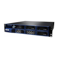
Juniper XRE200 - Datasheet (4 pages)
XRE200 Series EXTERNAL ROUTING ENGINE
Brand:
Juniper
| Category:
Network Router
| Size: 0 MB
Advertisement
Advertisement
Related Products
Juniper 6rd
Juniper ACX Series
Juniper ACX1000
Juniper ACX1100
Juniper ACX2000
Juniper ACX2100
Juniper ACX2200
Juniper ACX4000
Juniper ACX500
Juniper ACX5000
Juniper Categories
Network Router
Switch
Gateway
Software
Network Hardware
More Juniper Manuals
Login
Sign In
OR
Sign in with Facebook
Sign in with Google
Upload manual
Upload from disk
Upload from URL