Sign In
Upload
Manuals
Brands
Juniper Manuals
Network Router
ACX5000
Juniper ACX5000 Manuals
Manuals and User Guides for Juniper ACX5000. We have
1
Juniper ACX5000 manual available for free PDF download: Manual
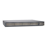
Juniper ACX5000 Manual (232 pages)
Universal Access Router
Brand:
Juniper
| Category:
Network Router
| Size: 4.84 MB
Table of Contents
Table of Contents
3
About the Documentation
15
Documentation and Release Notes
15
Documentation Conventions
15
Table 1: Notice Icons
16
Table 2: Text and Syntax Conventions
16
Documentation Feedback
17
About the Documentation
17
Requesting Technical Support
18
Self-Help Online Tools and Resources
18
Opening a Case with JTAC
18
Overview
21
System Overview and Architecture
21
Chassis Components and Descriptions
21
Cooling System Components and Descriptions
21
System Overview and Architecture
23
ACX5000 Universal Access Router Overview
23
ACX5048 Router
23
ACX5096 Router
24
Figure 1: ACX5048 Port Panel
24
Figure 2: ACX5096 Port Panel
24
ACX5000 Router Models
25
Field-Replaceable Units in an ACX5000 Router
25
System Overview and Architecture
25
Table 3: ACX5000 Router Model Numbers and Description
25
ACX5000 Universal Access Router Overview
25
Understanding Hardware Redundancy of an ACX5000 Router Components and Functionality
26
Table 4: Frus in ACX5000 Routers and Action Required before Removing
26
ACX5000 Routers Hardware and CLI Terminology Mapping
27
ACX5048 Router Hardware and CLI Terminology Mapping
27
Table 5: CLI Equivalents of Terms Used in Documentation for an ACX5048
27
ACX5096 Router Hardware and CLI Terminology Mapping
28
Figure 3: ACX5048 Interface Port Mapping
28
Table 6: CLI Equivalents of Terms Used in Documentation for an ACX5096
28
Figure 4: ACX5096 Interface Port Mapping
29
ACX5000 System Software Overview
30
Protocols and Applications Supported by the ACX Routers
30
Table 7: Protocols and Applications Supported by ACX Series Routers
30
Chassis Components and Descriptions
37
Management Panel of an ACX5000 Router
37
Figure 5: ACX5048, FRU End 1 U Product SKU
37
Them
37
Figure 6: ACX5096, FRU End 2 U Product SKU
38
Figure 7: Management Panel Components on ACX5048
38
Chassis Components and Descriptions
39
Figure 8: Management Panel Components on ACX5096
39
Port Panel of an ACX5048 Router
40
Port Panel of an ACX5096 Router
41
Router Ports
41
Figure 9: ACX5048 Router Port Panel
41
Figure 10: ACX5096 Router Port Panel
41
Channelizing Interfaces
42
Chassis Status Leds on an ACX5000 Router
43
Figure 11: Chassis Status Leds on an ACX5000 Routers
43
Management Port Leds on an ACX5000 Router
44
Table 8: Chassis Status Leds on an ACX5000 Router
44
Figure 12: Management Port Leds on an ACX5000 Router
45
Table 9: Management Port Leds on an ACX5000 Router
45
Access Port and Uplink Port Leds on an ACX5000 Router
46
Table 10: ACX5000 Access Port and Uplink LED Locations
47
Table 11: Network Port Leds on SFP+ Ports on an ACX5000 Router
47
Table 12: Network Port Leds on QSFP+ Ports on an ACX5000 Router
48
Fan Module LED on an ACX5000 Router
49
AC Power Supply Leds on an ACX5000 Router
49
Figure 13: Fan Module LED in an ACX5000 Router
49
Table 13: Fan Tray LED in an ACX5000 Router
49
Figure 14: AC Power Supply Leds on an ACX5000 Router
50
Table 14: AC Power Supply Leds on an ACX5000 Router
50
DC Power Supply Leds on an ACX5000 Router
51
Figure 15: DC Power Supply Faceplate on an ACX5000 Router
51
Table 15: DC Power Supply Leds on an ACX5000 Router
51
Cooling System Components and Descriptions
53
Cooling System and Airflow in an ACX5000 Router
53
Fan Modules
53
Figure 16: 1 U Fan Module Used in ACX5048
54
Figure 17: 2 U Fan Module Used in ACX5096
54
Cooling System Components and Descriptions
55
Figure 18: Air out Airflow through 1 U ACX5048 Chassis
55
Table 16: Fan Module in ACX5000 Routers
55
Fan Module Status
56
Figure 19: Air out Airflow through 2 U ACX5096 Chassis
56
Table 17: Fan Module LED
56
Power System Components and Descriptions
57
AC Power Supply for an ACX5000 Router
57
Figure 20: 1 U AC Power Supply in an ACX5048
58
Figure 21: 2 U AC Power Supply in an ACX5096
58
Figure 22: Power Supply Handle Detail
58
DC Power Supply for an ACX5000 Router
59
Power System Components and Descriptions
59
Table 18: Airflow Direction in an ACX5000 AC Power Supplies
59
Figure 23: DC Power Supply in ACX5048 Routers
60
Figure 24: DC Power Supply for an ACX5096
60
Power System Components and Descriptions
61
Figure 25: DC Power Supply Faceplate in ACX5000 Routers
61
Table 19: Airflow Direction in ACX5000 DC Power Supplies
61
Site Planning, Preparation, and Specifications
63
Preparation Overview
63
Port and Interface Specifications
63
Preparation Overview
65
Site Preparation Checklist for an ACX5000 Router
65
Table 20: Site Preparation Checklist
65
General Site Guidelines for an ACX Series Routers
66
Site Electrical Wiring Guidelines for an ACX Series Routers
67
Distance Limitations for Signaling
67
Radio Frequency Interference
67
Electromagnetic Compatibility
67
Preparation Overview
67
Environmental Requirements and Specifications for an ACX5000 Router
68
Table 21: ACX5000 Router Environmental Tolerances
68
Chassis Physical Specifications for an ACX5000 Router
69
Rack Requirements for an ACX5000 Router
69
Table 22: Physical Specifications for an ACX5000 Router Chassis
69
Cabinet Requirements for an ACX5000 Router
70
Table 23: Rack Requirements for an ACX5000 Router
70
Clearance Requirements for Airflow and Hardware Maintenance for an ACX5000
71
Router
71
Table 24: Cabinet Requirements for an ACX5000 Router
71
Figure 26: Clearance Requirements for Airflow and Hardware Maintenance for
72
Power Specifications and Requirements
73
AC Power Specifications for an ACX5000 Router
73
Table 25: AC Power Specifications for an ACX5000 Router
73
AC Power Cord Specifications for an ACX5000 Router
74
Table 26: AC Power Cord Specifications
74
DC Power Specifications for an ACX5000 Router
75
Power Specifications and Requirements
75
Table 27: DC Power Specifications for an ACX5000 Router
75
AC Power Cord Specifications for an ACX5000 Router
75
AC Power Supply for an ACX5000 Router
75
Port and Interface Specifications
77
USB Port Specifications for an ACX5000 Router
77
Console Port Connector Pinouts for an ACX5000 Router
78
Management Port Connector Pinouts for an ACX5000 Router
78
Table 28: Console Port Connector Pinouts for an ACX5000 Router
78
Interface Support for an ACX5000 Router
79
Table 29: RJ-45 Management Port Connector Pinouts for an ACX5000
79
Figure 27: Port Panel ACX5096
80
Figure 28: Port Panel ACX5048
80
Table 30: Supported Optical Transceivers for an ACX5000 Router
80
Table 31: Optics Being Qualified for ACX5048
81
Table 32: Supported DAC and DAC Breakout Cables for the ACX5000
81
Interface Specifications for SFP, SFP+, and QSFP+ Transceivers for an ACX5000 Router
82
Table 33: Copper Interface Support and Optical Interface Support for Gigabit Ethernet SFP Transceivers for ACX5000 Routers
83
Table 34: Optical Interface Support for 10-Gigabit Ethernet SFP+ Transceivers
86
Table 35: Interface Support for 40-Gigabit Ethernet QSFP+ Transceivers for
91
Interface Specifications for SFP+ DAC Cables for an ACX5000 Router
97
Table 36: Third-Party SFP+ DAC Cable Support
97
Table 37: SFP+ Passive Direct Attach Copper Cable Specifications
98
Table 38: SFP+ Active Direct Attach Copper Cable Specifications
100
Interface Specifications for QSFP+ DAC Breakout Cables for an ACX5000
102
Table 39: Third-Party QSFP+ DAC Breakout Cable Support
103
Table 40: QSFP+ DAC Passive Breakout Cable Specifications
103
Router
105
Table 41: QSFP+ Active DAC Breakout Cable Specifications
105
Interface Specifications for QSFP+ DAC Cables for an ACX5000 Router
106
Table 42: Third-Party QSFP+ DAC Cable Support
106
Table 43: Interface Specifications for Passive Copper QSFP+ DAC Cables
107
Table 44: Interface Specifications for Active Copper QSFP+ DAC Cables
109
Cable Specifications
111
Cable Specifications for QSFP+ and QSFP28 Transceivers
111
Table 45: QSFP+ MPO Cable Signals
111
Table 46: QSFP+ MPO Fiber-Optic Crossover Cable Pinouts
112
Cable Specifications for Console and Management Connections for an ACX5000
113
Router
113
Grounding Cable and Lug Specifications for an ACX5000 Router
113
Table 47: Cable Specifications for Console and Management Connections for
113
Understanding Fiber-Optic Cable Signal Loss, Attenuation, and Dispersion in an ACX5000 Router
114
Signal Loss in Multimode and Single-Mode Fiber-Optic Cables
114
Attenuation and Dispersion in Fiber-Optic Cable
115
Calculating Power Budget and Power Margin for Fiber-Optic Cables
115
Calculating Power Budget for Fiber-Optic Cable
116
Calculating Power Margin for Fiber-Optic Cable
116
Table 48: Estimated Values for Factors Causing Link Loss
116
Table
117
Initial Installation and Configuration
119
Unpacking the Router
121
Unpacking an ACX5000 Router
121
Table
121
Table 49: Inventory of Components Supplied with an ACX5000 Router
122
Installing the Router
123
Installing and Connecting an ACX5000 Router
123
Mounting an ACX5000 Router in a Rack or Cabinet
124
Before You Begin Rack Installation
124
Four Post Procedure
126
Figure 29: Attaching Mounting Rails to the ACX5048 Router
126
Figure 30: Attaching Mounting Rails to the ACX5096 Router
126
Figure 31: Attach 1 U Router to Rack
127
Figure 32: Slide Mounting Rail Onto the ACX5096 Rear Mounting Blade
127
Two Post Procedure
128
Figure 33: Slide Mounting Blades into 1 U Mounting Rail
128
Figure 34: Attaching a Two-Post Mounting Bracket to ACX5096 Router
128
Connecting the Router to Power
131
Connecting Earth Ground to an ACX5000 Router
132
Figure 35: Connecting a Grounding Cable to a 1 U ACX5048
133
Figure 36: Connecting a Grounding Cable to the 2 U ACX5096
133
Connecting AC Power to an ACX5000 Router
134
Figure 37: Connecting an AC Power Cord to an AC Power Supply in a 1 U
135
Figure 38: Connecting an AC Power Cord to an AC Power Supply in a 2 U
135
Connecting DC Power to an ACX5000 Router
136
Figure 39: DC Power Supply Faceplate for a ACX5000 Router
139
Figure 40: Securing Ring Lugs to the Terminals on the ACX5000 DC Power
139
Connecting the Router to the Network
141
Connecting an ACX5000 Router to a Management Console
141
Figure 41: Connecting the ACX Router to a Management Console through a Console Server
141
Connecting an ACX5000 Router to a Network for Out-Of-Band
142
Management
142
Figure 42: Connecting the ACX Router Directly to a Management Console
142
Figure 43: Connecting a ACX5000 Router to a Network for Out-Of-Band
143
Performing Initial Configuration
145
Configuring an ACX5000 Router
145
Installing, Maintaining, and Replacing Components
147
Removing the Router
149
Powering off an ACX5000 Router
149
Removing an ACX5000 Router from a Rack or Cabinet
151
Replacing Cooling System Component
153
Installing a Fan Module in an ACX5000 Router
153
Removing a Fan Module from an ACX5000 Router
154
Figure 44: Installing a Fan Module in a 1 U ACX5048
154
Figure 45: Installing a Fan Module in a 2 U ACX5096
154
Figure 46: Removing a Fan Module from a 1 U ACX5048
155
Figure 47: Removing a Fan Module from a 2 U ACX5096
155
Replacing Power Supply
157
Installing a Power Supply in an ACX5000 Router
157
Removing a Power Supply from an ACX5000 Router
158
Figure 48: Installing Power Supply in an ACX5048
158
Figure 49: Installing Power Supply in an ACX5096
158
Figure 50: Removing Power Supply from an ACX5048
160
Figure 51: Removing Power Supply from an ACX5096
160
Replacing Transceiver
161
Removing a Transceiver from an ACX5000 Router
161
Installing a Transceiver in an ACX5000 Router
162
Figure 52: Installing an SFP Transceiver
164
Figure 53: Installing a QSFP+ Transceiver-Vertical Orientation
164
Figure 54: Installing a QSFP+ Transceiver-Horizontal Orientation
164
Maintaining and Replacing Fiber-Optic Cable
165
Disconnecting a Fiber-Optic Cable from an ACX5000 Router
165
Connecting a Fiber-Optic Cable to an ACX5000 Router
166
Maintaining Fiber-Optic Cables in an ACX5000 Router
167
Contacting Customer Support and Returning the Chassis or Components
169
Contacting Customer Support
171
Locating Component Serial Numbers
173
Locating the Serial Number on an ACX5000 Router or Component
173
Listing the Chassis and Component Details Using the CLI
173
Locating the Chassis Serial Number ID Label on an ACX5000 Router
174
Locating the Serial Number ID Labels on FRU Components
175
Packing and Returning Components
177
Packing an ACX5000 Router or Component for Shipping
177
Packing an ACX5000 Router for Shipping
177
Packing an ACX5000 Router Components for Shipping
178
Returning an ACX5000 Router or Component for Repair or Replacement
178
Troubleshooting
181
Alarm Messages
183
Understanding the ACX5000 Router Alarms
183
Table 50: Alarm Terms and Definitions
183
ACX5000 Router Interface Alarm Messages
184
Safety and Compliance Information
185
General Safety Guidelines and Warnings
187
General Safety Guidelines for Juniper Networks Devices
187
Definition of Safety Warning Levels
188
General Safety Warnings for Juniper Networks Devices
190
Qualified Personnel Warning
190
Restricted Access Area Warning
190
Warning Statement for Norway and Sweden
192
Fire Safety Requirements
193
Fire Safety Requirements for Juniper Networks Devices
193
General Fire Safety Requirements
193
Fire Suppression
193
Fire Suppression Equipment
193
Radiation and Laser Warnings
195
Laser Safety Warnings for Juniper Networks Devices
195
Class 1 Laser Product Warning
195
Class 1 LED Product Warning
196
Laser Beam Warning
196
Radiation from Open Port Apertures Warning
197
Laser and LED Safety Guidelines and Warnings for the ACX Router
198
General Laser Safety Guidelines
198
Class 1M Laser Product Warning
198
Class 1M Laser Radiation Warning
199
Class 1 Laser Product Warning
199
Class 1 LED Product Warning
199
Laser Beam Warning
200
Unterminated Fiber-Optic Cable Warning
201
Installation and Maintenance Safety Information
203
Maintenance and Operational Safety Warnings for Juniper Networks Devices
203
Battery Handling Warning
203
Jewelry Removal Warning
204
Lightning Activity Warning
205
Operating Temperature Warning
206
Product Disposal Warning
207
Chassis Lifting Guidelines for an ACX5000 Router
208
Installation Safety Warnings for Juniper Networks Devices
208
Intra-Building Ports Warning
209
Installation Instructions Warning
209
Rack-Mounting Requirements and Warnings
209
Ramp Warning
213
Power and Electrical Safety Information
215
General Electrical Safety Warnings for Juniper Networks Devices
215
Grounded Equipment Warning
215
Grounding Requirements and Warning
216
Midplane Energy Hazard Warning
217
Multiple Power Supplies Disconnection Warning
217
Power Disconnection Warning
218
Preventing Electrostatic Discharge Damage to an ACX5000 Router
219
ACX5000 AC Power Electrical Safety Guidelines and Warnings
220
ACX5000 DC Power Electrical Safety Guidelines and Warnings
221
Agency Approvals and Compliance Statements
229
Agency Approvals for an ACX5000 Router
229
Compliance Statements for EMC Requirements for the ACX5000 Router
230
Canada
230
European Community
231
Israel
231
Japan
231
Korea
231
United States
232
Nonregulatory Environmental Standards
232
Advertisement
Advertisement
Related Products
Juniper ACX5048
Juniper ACX500
Juniper ACX5096
Juniper ACX5448
Juniper ACX5448-D
Juniper ACX5448-M
Juniper ACX5048-AC
Juniper ACX5048-DC
Juniper ACX5096-AC
Juniper ACX5096-DC
Juniper Categories
Network Router
Switch
Gateway
Software
Network Hardware
More Juniper Manuals
Login
Sign In
OR
Sign in with Facebook
Sign in with Google
Upload manual
Upload from disk
Upload from URL