Fujitsu ETERNUS AF250 S2 Manuals
Manuals and User Guides for Fujitsu ETERNUS AF250 S2. We have 8 Fujitsu ETERNUS AF250 S2 manuals available for free PDF download: Design Manual, Configuration Manual, Basic Operation Manual, Site Planning Manual, Safety Precautions
Advertisement
Fujitsu ETERNUS AF250 S2 Configuration Manual (171 pages)
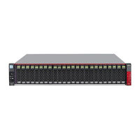
All-Flash Arrays Storage
Brand: Fujitsu
|
Category: Disk array system
|
Size: 6 MB
Table of Contents

Advertisement
Fujitsu ETERNUS AF250 S2 Configuration Manual (78 pages)
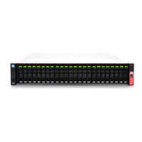
Hybrid Storage Systems / Disk Storage Systems / All-Flash Arrays, ETERNUS DX S4 Series, ETERNUS DX S3 Series. ETERNUS AF Series
Table of Contents
Fujitsu ETERNUS AF250 S2 Configuration Manual (75 pages)
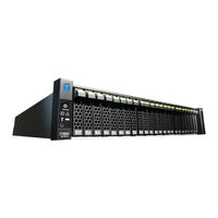
All-Flash Arrays, Hybrid Storage Systems, Disk Storage Systems, Power Synchronized Unit
Table of Contents


Fujitsu ETERNUS AF250 S2 Configuration Manual (18 pages)
Non-Stop Storage ETERNUS AF series and ETERNUS DX S4/S3 series
Table of Contents
Fujitsu ETERNUS AF250 S2 Safety Precautions (12 pages)
Hybrid Storage Systems, All-Flash Arrays, Power Synchronized Unit
Table of Contents
Advertisement