Sign In
Upload
Manuals
Brands
Danfoss Manuals
Media Converter
VLT 5000 FLUX
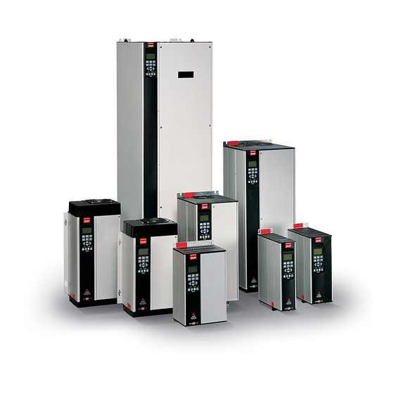
Danfoss VLT 5000 FLUX Frequency Converter Manuals
Manuals and User Guides for Danfoss VLT 5000 FLUX Frequency Converter. We have
6
Danfoss VLT 5000 FLUX Frequency Converter manuals available for free PDF download: Operating Instructions Manual, Service Manual
Danfoss VLT 5000 FLUX Operating Instructions Manual (159 pages)
Brand:
Danfoss
| Category:
DC Drives
| Size: 6 MB
Table of Contents
Table of Contents
1
Safety
3
How to Use this Manual
3
Software Version
3
Installation of Mechanical Brake
4
Safety Regulations
4
Use on Isolated Mains
4
Warning against Unintended Start
4
Abbreviations and Definitions
5
Frequency Converter
5
Introduction
5
Output
5
Switch NO/NC
5
Miscellaneous
6
Motor
6
References
6
Control Principle
8
Flux Vector Control Principle
8
Programmable Signal Outputs
8
Technology
8
Advanced Motor Protection
9
Advanced VLT Protection
9
Minor Interference on Mains
9
Reliable Galvanic Isolation
9
Key Diagram for VLT 5001–5027
10
Key Diagram for VLT 5122-5302 380-500V
11
Key Diagram for VLT 5032–5052 200–240 V
12
Key Diagram for VLT 5350-5500 380-500V
13
Mechanical Dimensions
14
Technical Data
14
Enclosure Type
17
Installation of VLT 5001-5302
17
Side by Side/Flange by Flange
17
Installation of VLT 5350-5500 380-500 V Compact
18
Ip 00 Vlt 5350 - 5500 380 - 500 V
18
Electrical Installation - Mains Supply
19
High Voltage Test
19
Motor Connection
19
Safety Earthing
19
Terminal Designation
19
Electrical Installation - Brake Resistor Temperature Switch
20
Electrical Installation - Loadsharing
20
Motor Shaft Direction
20
Tightening-Up Torques and Screw Sizes
21
Earth Leakage Current
22
Electrical Installation - 24 Volt External DC Supply
22
Electrical Installation - Relay Outputs
22
Extra Protection (RCD)
22
Compact IP 20/Nema 1
24
Compact IP 54
24
Electrical Installation, Power Cables
24
Installation of Control Cables
32
Terminal Designation
32
Connection of Encoder
33
Feedback System
33
Leds on Encoder Board
33
Bus Connection RS 232
35
Bus Termination
35
DIP Switches 1-4
35
Hardware Connection of the RS 232
35
2-Wire Start/Stop
36
Connection Examples
36
Pulse Start/Stop
36
Setup Change
36
Potentiometer Reference
37
Two-Wire Transmitter
37
Electrical Installation - EMC Precautions
38
Use of Emc-Correct Cables
40
Correct Earthing
41
Electrical Installation - Earthing of Control Cables
41
Wrong Earthing
41
Mains Supply Connected to Earth
42
Mains Supply Isolated from Earth
42
Position of RFI Switches
42
RFI Switch
42
Control Panel (LCP)
45
Leds
45
Display
45
Control Keys
45
Display Read-Out State
46
Display Mode
46
Local Control Keys
46
Display Mode - Selection of Read-Outstate
47
Structure for the Quick Menu Mode Versus the Menu Mode
47
Quick Setup Via Quick Menu
48
Menu Mode (Parameter Setting)
48
Changing Data
49
Changing a Text Value
49
Infinitely Variable Change of Numeric Data Value
49
Changing of Data Value, Step-By-Step
49
Initialisation to Factory Setting
50
Manual Initialisation
50
Local and Remote Control
51
Reference Handling
51
Handling of Single References
52
Handling of Multi-References
54
List of Handling of Multi-References
54
Programming of Stop at Torque Limit
55
Dynamic Brake Function(Brake Resistor)
56
Selection of Brake Resistor
56
Automatic Motor Adaptation, AMA
57
How to Perform an AMA
57
Limitations and Preconditions
57
Flying Start
58
Normal/High Overload Torque Control
59
Flying Start Is Active
59
Operation and Display
60
Changes During Operation
60
4-Setup:
60
Conversion Index
60
Programming
60
Active Setup
61
Language
61
Local Reference
61
Local/Remote Control
61
Copying of Setups
62
LCP Copy
62
Programming Setup
62
Display Line 2
63
Display Scaling Speed
63
Display Line 1.1
64
Display Line 1.2
64
Display Line 1.3
64
Local Operation Mode
64
Local Reset of Trip
65
Local Reversing
65
Local Stop
65
Lock for Data Change
65
Operating State at Power Up, Local Control
66
Quick Menu Setup
66
Userdefined Quick Menu
66
Load and Motor
67
Configuration
69
Motor Power
69
Torque Characteristics
69
Motor Current
70
Motor Frequency
70
Motor Voltage
70
Rated Motor Speed
70
Slip Compensation
71
Slip Compensation Time Constant
71
High Starting Torque
72
Start Delay (START DELAY)
72
Start Function (START FUNCTION)
72
DC Braking Current
73
DC Braking Time
73
DC Holding Current
73
Min. Speed for Activating Function at Stop
73
DC Brake Cut-In Speed
74
External Motor Fan
74
Motor Thermal Protection
74
Initial Current
75
Rotor Resistance
75
Start Speed
75
Stator Resistance
75
Iron Loss Resistance
76
Pole Number
76
Rotor Leakage Reactance
76
Stator Leakage Reactance
76
Functional Stop Delay, Par 163 - Flux
77
Mechanical Brake Initial Direction
77
Mechanical Brake Initial Torque
77
Mechanical Brake Release Delay
77
Minimum Intertia
77
References and Limits
79
Minimum Reference
80
Output Speed Range/Direction
80
Reference/Feedback Area
80
Maximum Reference
81
Ramp Type
81
Ramp-Down Time 1
81
Ramp-Up Time 1
81
Jog Ramp Time
82
Quick Stop Ramp-Down Time
82
Ramp-Down Time 2
82
Ramp-Up Time 2
82
Reference Function
83
Catch Up/Slow down Value
84
Torque Limit for Motor Mode
84
Torque Limit for Generating Operation
85
Warning: High Current
85
Warning: Low Current
85
Low Speed Current
86
Phase Loss Monitor
86
Warning: High Speed
86
Warning: Low Speed
86
Acceleration Jerk
87
Deceleration Jerk 1
87
Model Shift Speed
87
Introduction
88
Digital Input Functions
89
Analog Inputs
92
Terminal 53, Analog Input Voltage
93
Terminal 53, Min. Scaling
93
Terminal 54, Analog Input Voltage
93
Terminal 54, Min. Scaling
93
Function after Time out
94
Terminal 60, Max. Scaling
94
Terminal 60, Min. Scaling
94
Time out
94
Analog Outputs
95
Terminal 42 Output
95
Terminal 45, Output
95
Digital and Relay Outputs
96
Relay 01, off Delay
98
Relay 01, on Delay
98
Relay 01, Output
98
Relay 04, Output
98
Encoder Direction
99
Encoder Monitoring
99
Terminal 46, Digital Output
99
Terminal 46, Output, Pulse Scaling
99
Terminal 26, Digital Output
100
Terminal 26, Output, Pulse Scaling
100
Terminal 42, Output Maximum Scaling
100
Terminal 42, Output Minimum Scaling
100
KTY Sensor Type
101
Max Tracking Error
101
Special Functions
102
Brake Function/Overvoltage Control
103
Brake Power Limit, Kw
103
Brake Resistor, Ohm
103
Power Monitoring
103
Brake Check
104
Reset Function (RESET MODE)
104
Automatic Restart Time
105
Mains Failure, Par 407 - Flux
105
Trip Delay Torque
105
Flying Start
106
Speed Filt. Time
106
Speed PID Integral Time
106
Speed PID Proportional Gain
106
AEO Cos Phi
107
Inductance LC-Filter
107
LC-Filter Connected
107
Mains Voltage at Mains Fault
107
Adaptive Gain Max. Speed
108
Adaptive Gain Min. Speed
108
Adaptive Gain Scale
108
Serial Communication
109
Address
110
Coasting
110
DC-Brake
110
Quick-Stop
110
Bus Jog 1
111
Bus Jog 2
111
Reversing
111
Telegram Profile
111
Bus Time Interval Function
112
Digital Input, Parameter 528
113
Frequency, Parameter 518
113
Motor Current, Parameter 520
113
Torque, Parameter 521
113
Alarm Word, Parameter 538
114
Brake Power/Sec., Parameter 536
114
Heat Sink Temperature, Parameter 537
114
VLT Control Word, Parameter 539
114
Technical Functions
115
Hours Run, Parameter 601
116
Kwh Counter, Parameter 602:
116
Fault Log: Error Code
117
Fault Log: Time
117
Fault Log: Value
117
Reset of Kwh Counter
117
Operation Mode
118
Flash Test
119
Trouble-Shooting
120
Miscellaneous
120
Status Messages
121
Catch-Up (REM. CATCH UP)
121
Output Speed High (REM. SPEED HIGH)
121
Output Speed High (LOCAL SPEED HIGH)
121
Ramp Operation (REM. RAMPING)
122
Ramp Operation (LOCAL RAMPING)
122
Ramp Operation (MIXED RAMPING)
122
Running, Remote Control (REM. RUN OK)
122
Overvoltage Control
123
Automatic Motor Adaptation
123
List of Warnings and Alarms
124
Warnings
125
Alarm Messages
125
Undervoltage (DC LINK UNDERVOLT)
126
Brake Resistor Fault
127
Brake Resistor Power 100%
127
Brake Transistor Fault
127
Heat Sink Temperature too High
127
Motor Phase U Missing
128
Motor Phase V Missing
128
Out of Speed Range
128
Mains Failure (MAINS FAILURE)
128
Encoder Loss (ENCODER FAULT)
129
Tracking Fault
129
Appendix
131
Parameter Survey
131
General Technical Data
138
External 24 Volt DC Supply
141
Cable Lengths, Cross-Sections and Connectors
141
VLT 5000 Series Protection
142
Electrical Data
143
Bookstyle and Compact, Mains Supply
143
Compact, Mains Supply 3 X 200 - 240 V
144
Fuses
153
Non UL Compliance
154
Index
155
Advertisement
Danfoss VLT 5000 FLUX Service Manual (158 pages)
Brand:
Danfoss
| Category:
DC Drives
| Size: 11 MB
Table of Contents
Table of Contents
3
Introduction
9
Purpose
9
Vlt Product Overview
9
For Your Safety
9
Electrostatic Discharge (Esd)
9
Tools Required
11
Additional Tools Recommended for Testing
11
Exploded View D1 Frame Size
12
Exploded View D2 Frame Size
13
Exploded View E Frame Size
14
Section 1 Operator Interface and Drive Control
21
Introduction
21
Normal Display
21
Status Display
22
Factory Default Display Settings
22
Warnings and Alarms
26
Alarms
26
Warnings
26
Service Functions
26
Fault Message Table
27
Drive Inputs and Outputs
28
Input Signals
28
Output Signals
28
Control Terminals
29
Control Terminal Functions
29
Grounding Shielded Cables
31
Section 2 Internal Drive Operation
33
General
33
Description of Operation
33
Logic Section
33
Logic to Power Interface
34
Power Section
35
Sequence of Operation
36
Rectifier Section
36
Intermediate Section
38
Inverter Section
40
Brake Option
42
Cooling Fans
43
Load Sharing
43
Specific Card Connections
43
Section 3 Troubleshooting
45
Troubleshooting Tips
45
Exterior Fault Troubleshooting
45
Fault Symptom Troubleshooting
45
Visual Inspection
46
3 Fault Symptoms
47
Display
47
No Display
47
Intermittent Display
47
Display (Line 2) Flashing
47
WRONG or WRONG LCP Displayed
47
Motor
48
Motor will Not Run
48
Incorrect Motor Operation
49
Warning and Alarm Messages
50
After Repair Tests
57
Section 4 Drive and Motor Applications
59
Torque Limit, Current Limit, and Unstable Motor Operation
59
Overvoltage Trips
60
Mains Phase Loss Trips
60
Control Logic Problems
61
Programming Problems
61
Motor/Load Problems
61
Internal Drive Problems
62
Overtemperature Faults
62
Current Sensor Faults
62
Signal and Power Wiring Considerations for Drive Electromagnetic Compatibility
63
Effects of EMI
63
Sources of EMI
63
EMI Propagation
64
Signal Conductor Currents
64
Preventative Measures
65
Proper EMC Installation
66
Section 5 Test Procedures
67
Introduction
67
Tools Required for Testing
67
Signal Test Board
67
Test Cable
67
5 Test Procedures
68
Static Test Procedures
68
Soft Charge and Rectifier Circuits Test: D-Frame Size
69
Soft Charge Card Fuses
69
Soft Charge Rectifier Test: D-Frame Size
71
Soft Charge Card Connectors
71
Soft Charge and Rectifier Circuits Test: E-Frame Sizes
72
Soft Charge Card Fuse Location
72
Soft Charge Rectifier Test: E-Frame Size
74
Inverter Section Tests
75
Brake IGBT Test
76
Intermediate Section Tests
76
Heatsink Temperature Sensor Test
76
Fan Continuity Tests: D-Frame Size
77
Fan Continuity Tests: E-Frame Sizes
78
Dynamic Test Procedures
79
No Display Test
80
Input Voltage Test
80
Basic Control Card Voltage Test
80
Switch Mode Power Supply (SMPS) Test
81
Zero DC Bus Voltage Test
81
DC under Voltage Test
82
Input Phase Imbalance Test
82
Input Waveform Test
83
Input SCR Test
85
Output Phase Imbalance Test
86
IGBT Gate Drive Signals Test
87
IGBT Switiching Test
90
Brake IGBT Test
90
Current Sensors Test
91
Fan Tests
92
Input Terminal Signal Tests
93
Control Card Test
94
Initial Start up or after Repair Drive Tests
95
Section 6 D-Frame Sizes Disassembly and Assembly Instructions
97
Electrostatic Discharge (Esd)
97
6 Instructions
97
Control Card Cassette
97
Interface Card
98
Power Card
98
Control Card/Power Card Mounting Plate
98
Interface Card, Power Card, and Mounting Plate
98
Gate Drive Card
99
Soft Charge Card
99
Soft Charge Card Assy
99
Capacitor Bank(S)
100
Upper Capacitor Bank D2 Units
100
Lower Capacitor Bank D2 Units
100
Single Capacitor Bank D1 Units
101
Soft Charge (SC) Resistors D2 Units
102
Soft Charge Resistor
102
Soft Charge (SC) Resistors D1 Units
103
D2 Soft Charge Resistor
103
D1 Soft Charge Resistor
104
Input Terminal Mounting Plate Assy
106
Scr/Diode Module D2 Units
107
D2 Scr/Diode Module
110
D1 Scr/Diode Module
110
Scr/Diode Module D1 Units
111
Current Sensor
114
Fan Assembly
115
Fanassembly
115
AC Input Terminals
117
IGBT Modules D2 Units
118
D2 IGBT Modules
118
IGBT Modules D1 Units
121
Section 7 E-Frame Sizes Disassembly and Assembly Instructions
123
Electrostatic Discharge (Esd)
123
7 Instructions
123
Control Card Cassette
123
Interface Card
124
Power Card
124
Control Card/Power Card Mounting Plate
124
Gate Drive Card
125
Soft Charge Card
125
Capacitor Banks
126
Upper Capacitor Bank
126
Lower Capacitor Bank
126
Upper and Lower Capacitor Bank Assemblies
126
Input Terminal Mounting Plate Assy Option
127
Soft Charge Resistor
128
SCR and Diode Modules
129
Current Sensor
132
Current Sensors
132
Fan Assembly
133
Fanassembly
133
AC Input, Motor, Load Sharing or Regen Terminals
134
Terminal Blocks
134
IGBT Modules
135
Section 8 Special Test Equipment
139
Test Equipment
139
Test Cable and SCR Shorting Plug (P/N 176F8439)
139
Test Cable and SCR Shorting Plug
139
Signal Test Board (P/N 176F8437)
140
Signal Test Board Pin Outs: Description and Voltage Levels
140
Signal Test Board
140
Danfoss VLT 5000 FLUX Operating Instructions Manual (88 pages)
Synchronizing Controller
Brand:
Danfoss
| Category:
Controller
| Size: 1 MB
Table of Contents
Operating Instructions
2
Table of Contents
2
Safety Regulations
4
Introduction
5
Function Description
5
Speed Synchronization
5
Position Synchronization (Angle Synchronization)
5
Marker Synchronization
5
Mechanical Brake Control
6
List of Illustrations
6
Tips and Tricks for Synchronization Tasks
6
Figure 1: Calculation Example
6
Hardware
8
VLT Control Card Terminals
8
Technical Data
8
Option Card Terminals
8
Supply Voltages
9
Encoder Monitor
10
Option Card Layout
11
Technical Data
13
Examples of Encoder Interface Connections
15
Figure 6: Master-Slave Connection
15
Figure 7: Virtual Master-Slave Connection
15
Description of Terminals
16
Description of Field Bus Interface
21
Data Layout
21
Description of Parameters
23
Initializing the Parameters
37
Speed Synchronization
38
Figure 8: Control Behaviour with Speed Synchronization
38
Figure 9: Mixing. Speed Synchronizing Control
38
Function Diagrams for Speed Synchronization
39
Figure 10: Syncstart with Speed Synchronization
39
Syncstart
39
Up/Down Factor
39
Figure 11: Up/Down Factor with Speed Synchronization
40
Figure 12: Hold Speed
41
Gear Changing
41
Hold Function
41
Changing the Gear Ratio with an Analogue Value
42
Figure 13: Changing the Gear Ratio in Speed Synchronization
42
Application Example - Admixture
43
Description of Terminals and Terminal Configuration
43
Figure 14: Wiring Diagram - Batch Control
43
Setting the Parameters
44
How to Check the Motor Connection
45
How to Test the Incremental Encoders
45
How to Optimize the Controller
46
How to Program Synchronization
48
Operation and Operating Functions
49
Figure 15: Control Behaviour with Position Synchronization
50
Figure 16: Embossing with Position Synchronization
50
Position Synchronization (Angle Synchronization)
50
Figure 17: Synchronizing to a Stationary Master
51
Figure 18: Synchronizing to a Running Master
51
Syncstart to a Running Master
51
Syncstart to a Stationary Master
51
Figure 19: Position Displacement
52
Position Displacement with a Running Master
52
Function Diagrams for Position Synchronization
51
Application Example - Embossing Patterns on Mould
53
Description of Terminals and Terminal Configuration
53
Figure 20: Wiring Diagram - Application Example
53
Setting the Parameters
54
How to Check the Motor Connection
55
Testing the Incremental Encoders
55
How to Optimise the Controller
55
How to Program Synchronization
57
Operation and Operating Functions
59
Figure 21: Control Behaviour with Marker Synchronization
60
Figure 22: Conveyor Belt with Marker Synchronization
60
Marker Synchronizing
60
Figure 23: Initial Start-Up with Marker Synchronization
61
Marker Correction During Operation
61
Syncstart to a Running Master after Power on
61
Function Diagrams for Marker Synchronization
61
Application Example - Packaging
62
Figure 24: Marker Correction During Operation
62
Terminals and Terminal Configuration
63
Figure 26: Wiring Diagram - Conveyor Belt Regulation
63
Setting the Parameters
64
How to Check the Motor Connection
65
How to Test the Incremental Encoders
65
How to Optimise the Controller
66
How to Program Synchronization
68
Operation and Operating Functions
70
Appendix
71
Messages and Error Reference
71
Table of Error Messages
71
Parameter Overview
73
Glossary of Key Terms
81
Figure 27: Incremental Encoder Signals
81
Figure 28: Derivation of Quad Counts
81
Figure 29: Synchronization Without Virtual Master
82
Figure 30: Addition of the Cycle Times
83
Figure 31: Synchronization with Virtual Master
83
Figure 32: no Addition of the Cycle Times
84
List of Illustrations
85
Index
86
Advertisement
Danfoss VLT 5000 FLUX Operating Instructions Manual (63 pages)
Brand:
Danfoss
| Category:
Media Converter
| Size: 1 MB
Table of Contents
Table of Contents
2
MG.90.G1.02 - VLT Is a Registered Danfoss Trademark
2
Introduction
4
About this Manual
4
Assumptions
5
Background Knowledge
5
Profibus DP
6
Baudrate
6
Profibus DP V1
6
The PROFIBUS Option Card
7
Master-Controlled Frequency Converters
7
Bus Topology
8
Features of DP (Distributed Periphery)
8
Rapid Cyclical Transmission with PPO Using DP
8
Profibus DP V1
9
Principle of Data Exchange by Profibus DP V0/DP V1
9
Cable Lengths and Number of Nodes
10
Physical Connection
12
Protective Measures for EMC
12
Cable Connection FCM 300
12
Connection of the Cable Screening
12
Earthing
12
Bus Connection
12
Diagram Bus Connection
13
The PROFIBUS Option Card
13
Leds
14
Address Switches
15
Frequency Converter Response Time Behaviour
17
Time Behaviour During System Update
17
PPO Description
18
Communication Connections
18
PPO Description (Overview)
18
PCA Interface
19
PCA Processing
19
Parameter Description
20
Spontaneous Messages
22
SYNC and FREEZE
23
Sync/Unsync
23
Freeze/Unfreeze
23
Control Word/Status Word
24
Control Word According to Profidriveprofile
24
Status Word According to Profidriveprofile
26
Control Word According to Fc Standard
28
Status Word According to Fc Standard
29
Bus Reference Value
30
Examples
31
Example 1: PCV Channel
31
Example 2: Process Data from the Frequency Converter
32
Stw
32
Example 3: Array Treatment
33
GSD File
35
DP V1 Identifications
35
Parameters
36
VLT Frequency Converter Parameters
36
Parameter Access
43
Read/Write on VLT Frequency Converters
43
Warning and Alarm Messages
44
Warnings and Alarm Messages
44
Spontaneous Messages
44
Additional Display Readings
44
Warn. 34
44
Warnings
44
Warning Word, Extended Status Word and Alarm Word
45
Station Address
47
Extended Diagnosis
48
Parameter List
49
Appendix
59
Glossar
59
Abbreviations Used
60
Operating Instructions
63
Danfoss VLT 5000 FLUX Operating Instructions Manual (51 pages)
Positioning Controller
Brand:
Danfoss
| Category:
Controller
| Size: 1 MB
Table of Contents
Table of Contents
2
Table of Contents
4
Safety Regulations
4
Introduction
5
Hardware
6
VLT Control Card Terminals
6
Technical Data
6
Option Card Terminals
6
Supply Voltages
7
Encoder Monitor
8
Option Card Layout
9
Technical Data
11
Description of the Electrical and Field Bus Interface
13
Electrical Interface VLT
13
Option Card MK3A
15
Option Card MK3C
16
Option Card MK3B (Secondary Position Feedback for Absolute Encoders When Using VLT 5000 Flux)
16
Option Card MK3D (Primary Position Feedback)
17
Field Bus Interface
18
Data Layout
18
Description of the Available Parameters
21
Special LCP Functions
21
Description of Parameters
22
An Application Example
36
Wiring Diagram
37
Basic Set-Up
37
Parameter Settings
39
Troubleshooting
42
Frequently Asked Questions
42
Appendix
45
Binary Selection of Reference Positions Using Digital Control
45
Binary Selection of Reference Positions Using Fieldbus Control
45
Glossary of Key Terms
47
Index
49
Danfoss VLT 5000 FLUX Operating Instructions Manual (38 pages)
DeviceNet
Brand:
Danfoss
| Category:
Controller
| Size: 0 MB
Table of Contents
Table of Contents
2
Introduction to Danfoss VLT Series and Devicenet
3
Product Overview
3
Product and Environment
3
Overall Function
3
Network
3
User Profile
3
Data Communication Interface
3
Initialization of VLT Frequency Converter Interface
3
Network Variable Handling
4
Error Handling
4
Overall Function
4
Technical Data
6
Identity Object
6
Message Router
6
General Information
6
Network Power Supply
6
Cable Lengths
7
Cable Specifications
7
Cable Cross Section
8
Connection of the Cable Screen
9
VLT 2800 Earth Connection
9
Devicenet Connection
9
User Interface
10
Understanding Module Configuration Switches
11
EMC Precautions
12
Setting the Devicenet Node Address
13
Switch Settings for Devicenet Node Addressing
13
Setting the Baud Rate
13
VLT Response Time
14
General Purpose Discrete I/O
14
I/O Assembly Instances
14
Fieldbus Profile
15
Control Word
15
Status Word
17
Control Word under VLT Standard
19
Status Word under VLT Standard
20
Control Word and Status Word under Instance 20/70
21
Programming
22
Quick Setup
22
Special Attention
22
Warning and Alarm Messages
27
Factory Settings
28
Advertisement
Related Products
Danfoss VLT 5000 Series
Danfoss VLT 5000 Profibus
Danfoss VLT 5000
Danfoss VLT 5000 Crane Series
Danfoss VLT 5152
Danfoss VLT 5102
Danfoss VLT 5202
Danfoss VLT 6006
Danfoss VLT 6400
Danfoss VLT 6000 series
Danfoss Categories
Controller
DC Drives
Thermostat
Control Unit
Air Compressor
More Danfoss Manuals
Login
Sign In
OR
Sign in with Facebook
Sign in with Google
Upload manual
Upload from disk
Upload from URL