Sign In
Upload
Manuals
Brands
DAIKIN Manuals
Air Conditioner
Super Multi NX FTXS50G2V1B
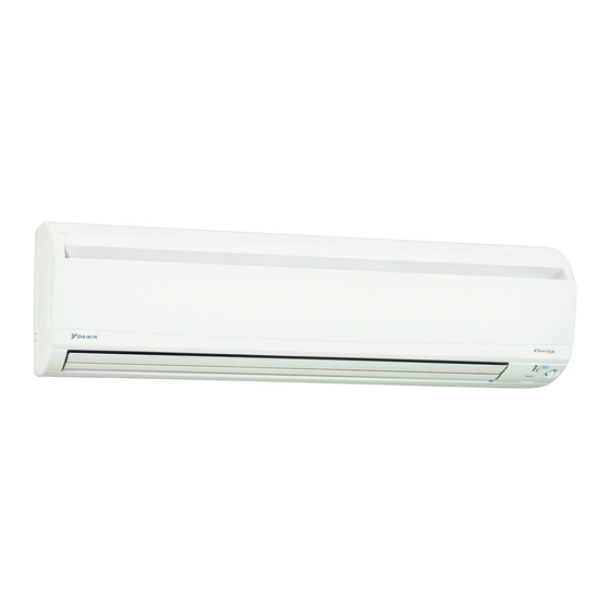
DAIKIN Super Multi NX FTXS50G2V1B Manuals
Manuals and User Guides for DAIKIN Super Multi NX FTXS50G2V1B. We have
10
DAIKIN Super Multi NX FTXS50G2V1B manuals available for free PDF download: Service Manual, Operation Manual, Technical Data Manual, Installation Manual
Daikin Super Multi NX FTXS50G2V1B Service Manual (501 pages)
E-Series, F-Series, G-Series
Brand:
Daikin
| Category:
Air Conditioner
| Size: 28.58 MB
Table of Contents
Table of Contents
4
Introduction
8
Safety Cautions
8
Used Icons
12
Part 1 List of Functions
13
Functions
14
Cooling Only - Indoor Unit
14
Cooling Only - Outdoor Unit
20
Heat Pump - Indoor Unit
21
Heat Pump - Outdoor Unit
28
Part 2 Specifications
29
Cooling Only - Indoor Unit
30
Cooling Only - Outdoor Unit
41
Heat Pump - Indoor Unit
43
Heat Pump - Outdoor Unit
57
Part 3 Printed Circuit Board Connector Wiring Diagram
61
Indoor Unit
62
Wall Mounted Type
62
Floor Standing Type
71
Floor / Ceiling Suspended Dual Type
73
Duct Connected Type
75
Ceiling Mounted Cassette Type
77
Ceiling Mounted Built-In Type
81
Ceiling Suspended Type
86
Remote Controller
88
Wired Remote Controller
88
Wireless Remote Controller
90
Outdoor Unit
92
Part 4 Function and Control
95
Function of Indoor Unit (RA Models)
96
Temperature Control
96
Frequency Principle
96
Operation Starting Control
98
Airflow Direction Control
99
Fan Speed Control for Indoor Units
101
Program Dry Operation
102
Automatic Operation
103
Thermostat Control
104
NIGHT SET Mode
106
ECONO Operation
107
HOME LEAVE Operation
108
2-Area INTELLIGENT EYE Operation
109
INTELLIGENT EYE Operation
111
Inverter POWERFUL Operation
112
Other Functions
114
Function of Indoor Unit (SA Models)
116
Drain Pump Control
116
Thermostat Sensor in Remote Controller
118
Freeze Prevention Control
120
Hot Start Control (in Heating Operation Only)
121
Function of Thermistor
122
Control Specification
124
Mode Hierarchy
124
Frequency Control
125
Controls at Mode Changing / Start-Up
128
Discharge Pipe Temperature Control
129
Input Current Control
130
Freeze-Up Protection Control
130
Heating Peak-Cut Control
131
Outdoor Fan Control
131
Liquid Compression Protection Function
132
Defrost Control
132
Low Hz High Pressure Limit
133
Electronic Expansion Valve Control
133
Pressure Equalizing Control
135
Malfunctions
138
Part 5 Operation Manual
140
System Configuration
141
RA Indoor Unit
142
FTXG, CTXG Series - ARC466A1
142
Name of Parts
144
Fan Operation
146
Operating Conditions
147
FTXS, FVXS Series - ARC452A1, A3
166
Names of Parts
172
Opening the Front Panel
173
ATXS, FLK(X)S, FDK(X)S Series - ARC433B67, B68, B69, B76
202
SA Indoor Unit - FFQ, FCQ, FDBQ, FBQ, FHQ Series
224
Brc1D528
224
Brc1E51A7
239
Operation Mode
242
Automatic Operation Mode
242
Program Dry
249
Key Lock
253
Airflow Direction
260
Ventilation Mode
264
Timer Settings
264
Schedule Timer
266
Holiday Setting
270
Convenient Functions
275
Contrast Adjustment
275
Clock Setting
278
Setting the Clock
278
Useful Information
283
Brc7E530W/531W, Brc7F532F/533F, Brc7Ea63W/66
284
Operation Range
287
Operation Procedure
288
Part 6 Service Diagnosis
296
Troubleshooting with LED
298
Indoor Unit
298
Outdoor Unit
300
Problem Symptoms and Measures
301
Service Check Function
302
RA Indoor Unit - F(C)TXG, FTXS, ATXS, FVXS, FLK(X)S, FDK(X)S Series
302
SA Indoor Unit - FFQ, FCQ, FDBQ, FBQ, FHQ Series
311
Code Indication on Remote Controller
318
RA Indoor Unit - F(C)TXG, FTXS, ATXS, FVXS, FLK(X)S
318
FDK(X)S Series
318
SA Indoor Unit - FFQ, FCQ, FDBQ, FBQ, FHQ Series
318
RA Indoor Unit - F(C)TXG, FTXS, ATXS, FVXS, FLK(X)S, FDK(X)S Series
318
Outdoor Unit
319
Troubleshooting for RA Indoor Unit - F(C)TXG, FTXS, ATXS, FVXS, FLK(X)S, FDK(X)S Series
320
Indoor Unit PCB Abnormality
320
Freeze-Up Protection Control or Heating Peak-Cut Control
321
Fan Motor or Related Abnormality
323
Thermistor or Related Abnormality (Indoor Unit)
326
Front Panel Open / Close Fault (FTXG and CTXG Series)
327
Signal Transmission Error (between Indoor Unit and Outdoor Unit)
328
Unspecified Voltage (between Indoor Unit and Outdoor Unit)
330
Troubleshooting for SA Indoor Unit - FFQ, FCQ, FDBQ, FBQ, FHQ Series
331
Indoor Unit PCB Abnormality
331
Drain Water Level System Abnormality
332
Fan Motor or Related Abnormality
334
Swing Motor Lock (FHQ Series)
336
Drain System Abnormality
337
Thermistor or Related Abnormality
338
Remote Controller Thermistor Abnormality
340
Signal Transmission Error
341
(Between Indoor Unit and Remote Controller)
341
Signal Transmission Error (between Indoor Unit and Remote Controller)
341
Signal Transmission Error
342
(Between MAIN Remote Controller and SUB Remote Controller)
342
Signal Transmission Error (between MAIN Remote Controller and SUB Remote Controller)
342
Field Setting Abnormality
343
Troubleshooting for Outdoor Unit
345
Anti-Icing Function
345
Outdoor Unit PCB Abnormality
347
OL Activation (Compressor Overload)
348
Compressor Lock
349
DC Fan Lock
350
Input Overcurrent Detection
351
Discharge Pipe Temperature Control
352
High Pressure Control in Cooling
353
Compressor Sensor System Abnormality
355
Position Sensor Abnormality
357
CT or Related Abnormality
359
Thermistor or Related Abnormality (Outdoor Unit)
361
Electrical Box Temperature Rise
363
Radiation Fin Temperature Rise
365
Output Overcurrent Detection
367
Refrigerant Shortage
369
Low-Voltage Detection or Over-Voltage Detection
371
Signal Transmission Error (on Outdoor Unit PCB)
372
Anti-Icing Function in Other Rooms / Unspecified Voltage (between Indoor and Outdoor Units)
373
Check
374
Thermistor Resistance Check
374
Fan Motor Connector Check
375
Hall IC Check
375
Power Supply Waveform Check
375
Electronic Expansion Valve Check
376
Four Way Valve Performance Check
377
Inverter Unit Refrigerant System Check
377
Inverter Checker" Check
378
Rotation Pulse Check on the Outdoor Unit PCB
379
Installation Condition Check
380
Discharge Pressure Check
380
Outdoor Fan System Check
381
Capacitor Voltage Check
381
Power Module Check
381
Part 7 Removal Procedure
382
Outdoor Unit - 50~75 Class
383
Removal of Outer Panels
383
Removal of Electrical Box
387
Removal of Pcbs
395
Removal of Outdoor Fan / Fan Motor
400
Removal of Sound Blankets
402
Removal of Coils / Thermistors
406
Removal of Distributor
409
Removal of Four Way Valve
410
Removal of Compressor
411
Outdoor Unit - 80/90 Class
413
Removal of Outer Panels
413
Removal of Electrical Box
429
Removal of Pcbs
435
Removal of Fan Motor
439
Removal of Coils / Thermistors
440
Removal of Sound Blankets
446
Removal of Compressor
449
Part 8 Trial Operation and Field Settings
450
Pump down Operation
451
Forced Operation
452
Wiring Error Check Function
453
Trial Operation
455
RA Indoor Unit - F(C)TXG, FTXS, ATXS, FVXS, FLK(X)S, FDK(X)S Series
455
SA Indoor Unit - FFQ, FCQ, FDBQ, FBQ, FHQ Series
457
Field Settings
459
RA Indoor Unit - F(C)TXG, FTXS, ATXS, FVXS, FLK(X)S, FDK(X)S Series
459
Jumper and Switch Settings
462
SA Indoor Unit - FFQ, FCQ, FDBQ, FBQ, FHQ Series
463
Outdoor Unit
471
Application of Silicon Grease to a Power Transistor and a Diode Bridge
474
Part 9 Appendix
475
Piping Diagrams
476
Indoor Unit
476
Outdoor Unit
482
Wiring Diagrams
487
Indoor Unit
487
Outdoor Unit
495
Advertisement
Daikin Super Multi NX FTXS50G2V1B Service Manual (341 pages)
Inverter Multi for 2 Rooms G-Series
Brand:
Daikin
| Category:
Air Conditioner
| Size: 19.3 MB
Table of Contents
Table of Contents
3
Introduction
7
Safety Cautions
7
Used Icons
11
Part 1 List of Functions
12
Functions
13
Cooling Only
13
Function and Control Part
15
Heat Pump
16
Part 2 Specifications
21
Specifications
22
Cooling Only - Indoor Unit
22
Cooling Only - Outdoor Unit
29
Heat Pump - Indoor Unit
31
Heat Pump - Outdoor Unit
40
Part 3 Printed Circuit Board Connector Wiring Diagram
42
Indoor Unit
43
Wall Mounted Type
43
Floor Standing Type
51
Floor / Ceiling Suspended Dual Type
53
Duct Connected Type
55
Ceiling Mounted Cassette Type
57
Remote Controller
59
Wired Remote Controller
59
Wireless Remote Controller
60
Outdoor Unit
61
2Mk(X)S40/50Gv1B, 2Mk(X)S40/50G2V1B
61
Part 4 Function and Control
63
Function of Indoor Unit (RA Models)
64
Temperature Control
64
Frequency Principle
64
Operation Starting Control
66
Airflow Direction Control
67
Fan Speed Control for Indoor Units
69
Program Dry Operation
70
Automatic Operation
71
Thermostat Control
72
NIGHT SET Mode
74
ECONO Operation
75
HOME LEAVE Operation
76
2-Area INTELLIGENT EYE Operation
77
INTELLIGENT EYE Operation
79
Inverter POWERFUL Operation
80
Other Functions
82
Function of Indoor Unit (SA Models)
84
Drain Pump Control
84
Thermostat Sensor in Remote Controller
86
Freeze Prevention Control
88
Hot Start Control (in Heating Operation Only)
89
Function of Thermistor
90
Control Specification
92
Mode Hierarchy
92
Frequency Control
94
Controls at Mode Changing / Start-Up
97
Discharge Pipe Temperature Control
98
Compressor Protection Function
98
Input Current Control
99
Freeze-Up Protection Control
99
Heating Peak-Cut Control
100
Outdoor Fan Control
100
Liquid Compression Protection Function
101
Defrost Control
101
Electronic Expansion Valve Control
102
Malfunctions
106
Part 5 Operation Manual
109
System Configuration
110
RA Indoor Unit
111
FTXG-J, CTXG-J Series - ARC466A1
111
Fan Operation
115
Operating Conditions
116
FTXS, FVXS Series - ARC452A1, A3
133
Names of Parts
137
Opening the Front Panel
137
FTXG-E, CTXG-E, FLK(X)S, FDK(X)S Series
160
Arc433B41, B67, B68, B69, B76
160
FTXG-E, CTXG-E, FLK(X)S, FDK(X)S Series ARC433B41, B67, B68, B69, B76
160
Adjusting the Air Flow Direction
166
SA Indoor Unit - FFQ Series
179
Brc1D528
179
Brc7E530W/531W
194
Names and Functions
195
Operation Range
197
Operation Procedure
198
Part 6 Service Diagnosis
206
Troubleshooting with LED
208
Indoor Unit
208
Outdoor Unit
209
Problem Symptoms and Measures
210
Service Check Function
211
SA Indoor Unit - FFQ Series
220
RA Indoor Unit - F(C)TXG, FTXS, FVXS, FLK(X)S
224
FDK(X)S Series
224
Code Indication on Remote Controller
224
RA Indoor Unit - F(C)TXG, FTXS, FVXS, FLK(X)S, FDK(X)S Series
224
SA Indoor Unit - FFQ Series
224
Outdoor Unit
225
Troubleshooting for RA Indoor Unit - F(C)TXG, FTXS, FVXS, FLK(X)S, FDK(X)S Series
226
Indoor Unit PCB Abnormality
226
Freeze-Up Protection Control or Heating Peak-Cut Control
227
Fan Motor or Related Abnormality
229
Thermistor or Related Abnormality (Indoor Unit)
232
Front Panel Open / Close Fault (FTXG, CTXG)
233
Troubleshooting for SA Indoor Unit - FFQ Series
234
Indoor Unit PCB Abnormality
234
Drain Water Level System Abnormality
235
Fan Motor or Related Abnormality
237
Drain System Abnormality
238
Thermistor or Related Abnormality
239
Remote Controller Thermistor Abnormality
241
Signal Transmission Error
242
(Between Indoor Unit and Remote Controller)
242
Signal Transmission Error (between Indoor Unit and Remote Controller)
242
Signal Transmission Error
243
(Between MAIN Remote Controller and SUB Remote Controller)
243
Signal Transmission Error (between MAIN Remote Controller and SUB Remote Controller)
243
Field Setting Abnormality
244
Troubleshooting for Outdoor Unit
246
Anti-Icing Control for Indoor Unit
246
OL Activation (Compressor Overload)
248
Compressor Lock
249
DC Fan Lock
250
Input Overcurrent Detection
251
Discharge Pipe Temperature Control
252
High Pressure Control in Cooling
253
Compressor Sensor System Abnormality
254
Position Sensor Abnormality
255
DC Voltage / Current Sensor Abnormality
257
Thermistor or Related Abnormality (Outdoor Unit)
258
Electrical Box Temperature Rise
260
Radiation Fin Temperature Rise
261
Output Overcurrent Detection
263
Refrigerant Shortage
265
Low-Voltage Detection or Over-Voltage Detection
267
Outdoor Unit PCB Abnormality or Signal Transmission Error
268
Unspecified Voltage (between Indoor Unit and Outdoor Unit) / Anti-Icing Control in Other Room
271
Check
272
Thermistor Resistance Check
272
Fan Motor Connector Output Check
273
Hall IC Check
273
Power Supply Waveforms Check
273
Electronic Expansion Valve Check
274
Four Way Valve Performance Check
275
Inverter Unit Refrigerant System Check
276
Inverter Checker" Check
277
Rotating Pulse Input on the Outdoor Unit PCB Check
279
Installation Condition Check
280
Discharge Pressure Check
280
Outdoor Unit Fan System Check
281
Main Circuit Short Check
281
Power Module Check
282
Part 7 Removal Procedure
283
Outdoor Unit
284
Removal of Outer Panels
284
Removal of Electrical Box
286
Removal of PCB
291
Removal of Sound Blankets
296
Removal of Outdoor Fan / Fan Motor
298
Removal of Thermistors
301
Removal of Four Way Valve / Electronic Expansion Valves
303
Removal of Compressor
306
Part 8 Trial Operation and Field Settings
308
Pump down Operation
309
Forced Cooling Operation
310
Trial Operation
311
RA Indoor Unit - F(C)TXG, FTXS, FVXS, FLK(X)S
311
FDK(X)S Series
311
RA Indoor Unit - F(C)TXG, FTXS, FVXS, FLK(X)S, FDK(X)S Series
311
SA Indoor Unit - FFQ Series
313
Field Settings
314
RA Indoor Unit - F(C)TXG, FTXS, FVXS, FLK(X)S
314
FDK(X)S Series
314
Model Type Setting
314
RA Indoor Unit - F(C)TXG, FTXS, FVXS, FLK(X)S, FDK(X)S Series
314
When 2 Units Are Installed in 1 Room
314
Jumper and Switch Settings
317
SA Indoor Unit - FFQ Series
318
Outdoor Unit
325
Jumper Settings
325
Application of Silicon Grease to a Power Transistor and a Diode Bridge
326
Part 9 Appendix
327
Piping Diagrams
328
Indoor Unit
328
Outdoor Unit
332
Wiring Diagrams
334
Indoor Unit
334
Outdoor Unit
338
Daikin Super Multi NX FTXS50G2V1B Service Manual (316 pages)
G-Series
Brand:
Daikin
| Category:
Heat Pump
| Size: 10.53 MB
Table of Contents
Table of Contents
4
Introduction
8
Safety Cautions
8
Used Icons
12
Part 1 List of Functions
13
Functions
14
Cooling Only
14
Heat Pump
15
Part 2 Specifications
17
Specifications
18
Cooling Only
18
Specifications
19
Heat Pump
21
Part 3 Printed Circuit Board Connector Wiring Diagram
29
Printed Circuit Board Connector Wiring Diagram
30
Indoor Unit
30
Outdoor Unit
33
Part 4 Function and Control
41
Main Functions
42
Frequency Principle
42
Airflow Direction Control
44
Fan Speed Control for Indoor Units
45
Program Dry Operation
46
Automatic Operation
47
Thermostat Control
48
NIGHT SET Mode
49
ECONO Operation
50
2-Area INTELLIGENT EYE Operation
51
INTELLIGENT EYE Operation
53
Inverter POWERFUL Operation
54
Other Functions
55
Function of Thermistor
56
Control Specification
57
Mode Hierarchy
57
Frequency Control
58
Controls at Mode Changing / Start-Up
60
Discharge Pipe Temperature Control
62
Input Current Control
63
Freeze-Up Protection Control
65
Heating Peak-Cut Control
65
Outdoor Fan Control
66
Liquid Compression Protection Function
66
Defrost Control
67
Electronic Expansion Valve Control
68
Malfunctions
71
Forced Operation Mode
72
Standby Electricity Saving
72
Part 5 Operation Manual
73
System Configuration
74
Ftxs20/25/35/42/50G2V1B
75
Remote Control
75
Auto Dry Cool Heat Fan Operation
76
AUTO · DRY · COOL · HEAT · FAN Operation
76
Adjusting the Airflow Direction
78
COMFORT AIRFLOW and INTELLIGENT EYE Operation
80
POWERFUL Operation
83
OUTDOOR UNIT QUIET Operation
84
ECONO Operation
85
TIMER Operation
86
WEEKLY TIMER Operation
88
Atxs20/25/35/42/50G2V1B
93
Remote Control
93
Auto Dry Cool Heat Fan Operation
94
AUTO · DRY · COOL · HEAT · FAN Operation
94
Adjusting the Airflow Direction
96
COMFORT AIRFLOW Operation
98
INTELLIGENT EYE Operation
99
POWERFUL Operation
101
OUTDOOR UNIT QUIET Operation
102
ECONO Operation
103
TIMER Operation
104
Part 6 Service Diagnosis
106
Caution for Diagnosis
107
Troubleshooting with LED
107
Problem Symptoms and Measures
108
Service Check Function
109
ARC452 Series
109
ARC433 Series
112
Troubleshooting
115
Error Codes and Description
115
Indoor Unit PCB Abnormality
116
Freeze-Up Protection Control or Heating Peak-Cut Control
117
Fan Motor (DC Motor) or Related Abnormality
119
Thermistor or Related Abnormality (Indoor Unit)
121
Signal Transmission Error (between Indoor Unit and Outdoor Unit)
122
Unspecified Voltage (between Indoor Unit and Outdoor Unit)
123
Outdoor Unit PCB Abnormality
124
OL Activation (Compressor Overload)
126
Compressor Lock
127
DC Fan Lock
128
Input Overcurrent Detection
129
Four Way Valve Abnormality
130
Discharge Pipe Temperature Control
132
High Pressure Control in Cooling
134
Compressor System Sensor Abnormality
136
Position Sensor Abnormality
138
DC Voltage / Current Sensor Abnormality (20/25/35/42 Class)
141
CT or Related Abnormality (50 Class)
142
Thermistor or Related Abnormality (Outdoor Unit)
144
Electrical Box Temperature Rise
146
Radiation Fin Temperature Rise
148
Output Overcurrent Detection
150
Refrigerant Shortage
152
Low-Voltage Detection or Over-Voltage Detection
155
Signal Transmission Error on Outdoor Unit PCB
157
(50 Class Only)145
157
Signal Transmission Error on Outdoor Unit PCB (50 Class Only)
157
Check
158
How to Check
158
Four Way Valve Performance Check
159
Thermistor Resistance Check
160
Installation Condition Check
161
Discharge Pressure Check
161
Outdoor Fan System Check
162
Power Supply Waveforms Check
162
Capacitor Voltage Check
163
Power Module Check
163
Rotation Pulse Check on the Outdoor Unit Pcb
164
Main Circuit Short Check
165
Indoor Unit
167
Removal of Air Filter
167
Removal of Front Panel
169
Removal of Front Grille
171
Removal of Horizontal Blades / Vertical Blades
174
Removal of Electrical Box
177
Removal of PCB
180
Removal of Indoor Heat Exchanger
185
Removal of Swing Motors
188
Removal of Fan Motor
192
Outdoor Unit - RK(X)S20-35G2V1B, ARXS20-35G2V1B
195
Removal of Outer Panels / Fan Motor
195
Removal of Electrical Box
204
Removal of Thermistors
208
Removal of PCB
210
Removal of Reactor / Partition Plate
213
Removal of Sound Blanket
215
Removal of Four Way Valve
216
Removal of Compressor
219
Outdoor Unit - RK(X)S20-35G2V1B9
221
Removal of Outer Panels / Fan Motor
221
Outdoor Unit - RK(X)S20-35G2V1B9, ARXS20-35G3V1B
221
Removal of Electrical Box
230
Removal of PCB
233
Removal of Reactor / Partition Plate
241
Removal of Sound Blanket
243
Removal of Four Way Valve
245
Removal of Compressor
248
Outdoor Unit - RK(X)S42G2V1B, ARXS42G2V1B
250
Removal of Outer Panels
250
Removal of Electrical Box
252
Removal of PCB
257
Removal of Sound Blanket
262
Removal of Outdoor Fan / Fan Motor
264
Removal of Thermistors
267
Removal of Four Way Valve / Electronic Expansion Valve
268
Removal of Compressor
271
Outdoor Unit - RK(X)S50G2V1B, ARXS50G2V1B
274
Removal of Outer Panels
274
Removal of Outdoor Fan / Fan Motor
278
Removal of Electrical Box
282
Removal of PCB
287
Removal of Sound Blanket / Thermistors
290
Removal of Four Way Valve
292
Removal of Electronic Expansion Valve
293
Removal of Compressor
294
Trial Operation
298
Part 8 Trial Operation and Field Settings
298
Trial Operation
299
Field Settings
300
Field Settings
301
Model Type Setting
301
When 2 Units Are Installed in 1 Room
301
Standby Electricity Saving
302
Facility Setting Jumper and Switch (Cooling at Low Outdoor Temperature)
303
Jumper and Switch Settings
303
Jumper and Switch Settings
304
Application of Silicon Grease to a Power Transistor and a Diode Bridge
305
Part 9 Appendix
306
Piping Diagrams
307
Indoor Unit
307
Outdoor Unit
308
Outdoor Unit
311
Wiring Diagrams
312
Indoor Unit
312
Advertisement
Daikin Super Multi NX FTXS50G2V1B Service Manual (289 pages)
Inverter Multi for 2 Rooms
Brand:
Daikin
| Category:
Air Conditioner
| Size: 14.04 MB
Table of Contents
Table of Contents
3
Introduction
6
Safety Cautions
6
Used Icons
10
Part 1 List of Functions
11
List of Functions
12
Cooling Only Models
12
Heat Pump Models
17
Part 2 Specifications
24
Specifications
25
Indoor Units - Cooling Only
25
Duct Connected Type
27
Floor Standing Type
29
Ceiling Mounted Cassette Type
30
Outdoor Units - Cooling Only
31
Indoor Units - Heat Pump
33
Outdoor Units - Heat Pump
43
Part 3 Printed Circuit Board Connector Wiring Diagram
45
Printed Circuit Board Connector Wiring Diagram
46
Wall Mounted Type
46
Duct Connected Type
53
Floor / Ceiling Suspended Dual Type
55
Floor Standing Type
58
Ceiling Mounted Cassette Type (600×600)
60
Outdoor Units
63
Part 4 Function and Control
65
Main Functions
66
Temperature Control
66
Frequency Principle
66
Power-Airflow Flaps, Wide-Angle Louvers, Auto-Swing, COMFORT AIRFLOW Mode and 3-D Airflow
68
Operation Starting Control
70
Fan Speed Control for Indoor Units
71
Program Dry Function
73
Automatic Operation
74
Thermostat Control
75
Night Set Mode
76
ECONO Mode
77
Area Intelligent Eye (Ftxs)
78
Intelligent Eye (Atxs, Ftxg, Atxg, Ctxg)
80
HOME LEAVE Operation
82
Inverter POWERFUL Operation
83
Other Functions
84
Weekly Timer Operation
85
Function of Thermistor
86
Heat Pump Model
86
Cooling Only Model
88
Control Specification
89
Mode Hierarchy
89
Frequency Control
90
Controls at Mode Changing / Start-Up
93
Compressor Protection Function
94
Discharge Pipe Temperature Control
95
Input Current Control
95
Freeze-Up Protection Control
96
Heating Peak-Cut Control
96
Fan Control
97
Liquid Compression Protection Function 2
97
Defrost Control
98
Electronic Expansion Valve Control
99
Malfunctions
103
Additional Function
104
Part 5 Operation Manual
105
System Configuration
106
Operation Instructions
106
Instruction
107
ATXS, ATX, FTXG, CTXG, ATXG, FDK(X)S, FLK(X)S Series
107
Remote Controller
108
Adjusting the Airflow Direction
115
Adjusting the Air Flow Direction
119
Comfort Airflow Operation
123
Powerful Operation
124
Outdoor Unit Quiet Operation
125
Econo Operation
126
Intelligent Eye Operation
130
Timer Operation
134
To Use on Timer Operation
135
Note for Multi System
136
FTXS, FVXS Series
138
Comfort Airflow and Intelligent Eye Operation
147
Quiet Operation
151
FFQ Series
162
Safety Considerations
164
Installation Site
165
Operation Range
165
Switch and Display on the Remote Controller
166
Operation Procedure
166
Trouble Shooting
172
Part 6 Service Diagnosis
173
Caution for Diagnosis
174
Problem Symptoms and Measures
176
Service Check Function
177
ARC433 Series
177
ARC452 Series
180
Troubleshooting
183
Error Codes and Description
183
Indoor Unit PCB Abnormality
184
Freeze-Up Protection Control or High Pressure Control
185
Fan Motor or Related Abnormality
187
Thermistor or Related Abnormality (Indoor Unit)
191
Front Panel Open / Close Fault
192
Freeze-Up Protection Control
193
OL Activation (Compressor Overload)
195
Compressor Lock
196
DC Fan Lock
197
Input Overcurrent Detection
198
Discharge Pipe Temperature Control
200
High Pressure Control in Cooling
201
Compressor Sensor System Abnormality
203
Position Sensor Abnormality
204
DC Voltage / DC Current Sensor Abnormality
206
Thermistor or Related Abnormality (Outdoor Unit)
207
Electrical Box Temperature Rise
209
Radiation Fin Temperature Rise
211
Output Overcurrent Detection
213
Refrigerant Shortage
215
Over-Voltage Detection / Low-Voltage Detection
217
Anti-Icing Function in Other Rooms / Unspecified Voltage (between Indoor and Outdoor Units)
218
Outdoor Unit PCB Abnormality or Signal Transmission Circuit Abnormality
219
Check
222
How to Check
222
Electronic Expansion Valve Check
223
Four Way Valve Performance Check
224
Thermistor Resistance Check
225
Installation Condition Check
226
Discharge Pressure Check
227
Power Supply Waveforms Check
227
Power Transistor Check
228
Hall IC Check
231
Part 7 Removal Procedure
235
Outdoor Unit
236
Removal of the Panels and Plates
236
Removal of the Electrical Box
238
Removal of the PCB
243
Removal of the Sound Blanket
248
Removal of the Outdoor Fan / Fan Motor
250
Removal of the Thermistors
253
Removal of the Compressor
255
Removal of the Four Way Valve / Electronic Expansion Valve
257
Part 8 Trial Operation and Field Settings
259
Pump down Operation
260
Forced Cooling Operation Mode
261
Trial Operation
262
Indoor Unit - ATX, ATXS, ATXG, F(C)TXG, FTXS, FDK(X)S, FLK(X)S, FVXS Series
262
Indoor Unit - FFQ Series
264
Field Settings
265
RA Indoor Unit - ATX, ATXS, ATXG, F(C)TXG, FTXS, FDK(X)S, FLK(X)S, FVXS Series
265
Jumper and Switch Settings
268
Indoor Unit - FFQ Series
269
Outdoor Unit
272
Maximum Power Input Limitation Setting
273
Application of Silicon Grease to a Power Transistor and a Diode Bridge
274
Part 9 Appendix
275
Piping Diagrams
276
Indoor Units
276
Outdoor Units
280
Heat Pump
281
Wiring Diagrams
282
Indoor Units
282
Outdoor Units
287
Daikin Super Multi NX FTXS50G2V1B Operation Manual (38 pages)
DAIKIN ROOM AIR CONDITIONER
Brand:
Daikin
| Category:
Air Conditioner
| Size: 3.61 MB
Table of Contents
Operation Manual
1
Table of Contents
2
Safety Precautions
3
Installation Site
4
Electrical Work
4
Names of Parts
5
Outdoor Unit
6
Indoor Unit
6
Remote Controller
7
To Set the Batteries
8
Preparation before Operation
8
Operation
9
Operation
10
AUTO · DRY · COOL · HEAT · FAN Operation
11
To Change the Airflow Rate Setting
12
Adjusting the Airflow Direction
13
Comfort Airflow Operation
14
COMFORT AIRFLOW and INTELLIGENT EYE Operation
15
POWERFUL Operation
18
OUTDOOR UNIT QUIET Operation
19
ECONO Operation
20
TIMER Operation
21
To Combine on Timer and off Timer
22
WEEKLY TIMER Operation
23
Note for Multi System
28
Priority Room Setting
29
Care and Cleaning
30
Air Filter
31
Before a Long Idle Period
32
Trouble Shooting
33
Check Again
34
Call the Service Shop Immediately
35
Disposal Requirements
35
Important Information Regarding the Refrigerant Used
35
Fault Diagnosis
36
DAIKIN Super Multi NX FTXS50G2V1B Operation Manual (38 pages)
Inverter
Brand:
DAIKIN
| Category:
Air Conditioner
| Size: 3.51 MB
Table of Contents
Operation Manual
1
Table of Contents
2
Safety Precautions
3
Installation Site
4
Electrical Work
4
Names of Parts
5
Outdoor Unit
6
Indoor Unit
6
Remote Controller
7
To Set the Batteries
8
Preparation before Operation
8
To Set the Clock
9
AUTO · DRY · COOL · HEAT · FAN Operation
11
To Change the Airflow Rate Setting
12
Adjusting the Airflow Direction
13
Comfort Airflow Operation
14
COMFORT AIRFLOW and INTELLIGENT EYE Operation
15
POWERFUL Operation
18
OUTDOOR UNIT QUIET Operation
19
ECONO Operation
20
TIMER Operation
21
To Combine on Timer and off Timer
22
WEEKLY TIMER Operation
23
Note for Multi System
28
Care and Cleaning
30
Air Filter
31
Before a Long Idle Period
32
Trouble Shooting
33
Check Again
34
Call the Service Shop Immediately
35
Disposal Requirements
35
Important Information Regarding the Refrigerant Used
35
Fault Diagnosis
36
Daikin Super Multi NX FTXS50G2V1B Service Manual (40 pages)
REMOVAL PROCEDURE
Brand:
Daikin
| Category:
Heat Pump
| Size: 3.35 MB
Table of Contents
Table of Contents
3
Removal of Air Filters
4
Removal of Front Panel
6
Removal of Front Grille
7
Removal of Horizontal Blades / Vertical Blades
9
Removal of Electrical Box
13
Removal of Pcbs (Pattern 1)
16
Removal of Pcbs (Pattern 2)
22
Removal of Swing Motors (Pattern 1)
26
Removal of Swing Motors (Pattern 2)
30
Removal of Indoor Heat Exchanger
33
Removal of Fan Motor
36
Daikin Super Multi NX FTXS50G2V1B Installation Manual (17 pages)
Brand:
Daikin
| Category:
Air Conditioner
| Size: 2.62 MB
Table of Contents
Safety Precautions
3
Choosing an Installation Site
4
Indoor Unit
4
Wireless Remote Controller
4
Installation Tips
5
Removing and Installing Front Panel
5
Removing and Installing Front Grille
5
How to Set the Different Addresses
6
When Connecting to an HA System
6
Indoor Unit Installation Drawings
8
Indoor Unit Installation
9
Installing the Mounting Plate
9
Boring a Wall Hole and Installing Wall Embedded Pipe
10
Installing Indoor Unit
10
Drain Piping
12
Refrigerant Piping Work
13
Flaring the Pipe End
13
Pump down Operation
14
Trial Operation and Testing
15
Test Items
15
Daikin Super Multi NX FTXS50G2V1B Technical Data Manual (18 pages)
Indoor units FTXS-G Series
Brand:
Daikin
| Category:
Air Conditioner
| Size: 3.22 MB
Table of Contents
Technical Data
1
Table of Contents
3
1 Features
4
2 Specifications
5
Technical Specifications
5
Electrical Specifications
7
3 Dimensional Drawing & Centre of Gravity
8
Dimensional Drawing
8
Centre of Gravity
10
4 Piping Diagram
11
5 Wiring Diagram
13
6 Sound Data
14
Sound Pressure Spectrum
14
Daikin Super Multi NX FTXS50G2V1B Installation Manual (16 pages)
R410A Split Series
Brand:
Daikin
| Category:
Air Conditioner
| Size: 2.29 MB
Table of Contents
Safety Precautions
3
Choosing an Installation Site
4
Indoor Unit
4
Wireless Remote Controller
4
Installation Tips
5
How to Set the Different Addresses
6
Indoor Unit Installation Drawings
7
Indoor Unit Installation
8
Installing Indoor Unit
9
Left-Side, Left-Back, or Left Bottom Piping
10
Wall Embedded Piping
10
Drain Piping
11
Refrigerant Piping Work
12
Pump down Operation
13
Trial Operation and Testing
14
Advertisement
Related Products
Daikin FTXS50GVMA
Daikin FTXS50GVMV
Daikin FTXS50JVMA
Daikin FTXS50KVMA
Daikin FTXS50MVLT
Daikin FTXS50LVMA
Daikin FTXS50LVMN
Daikin FTXS50AXV1G
Daikin FTXS50KAVMN
Daikin FTXS50A
DAIKIN Categories
Air Conditioner
Heat Pump
Remote Control
Chiller
Fan
More DAIKIN Manuals
Login
Sign In
OR
Sign in with Facebook
Sign in with Google
Upload manual
Upload from disk
Upload from URL