Sign In
Upload
Manuals
Brands
Canon Manuals
Copier
imagePRESS 1135
Canon imagePRESS 1135 Manuals
Manuals and User Guides for Canon imagePRESS 1135. We have
2
Canon imagePRESS 1135 manuals available for free PDF download: Service Manual, Media Manual
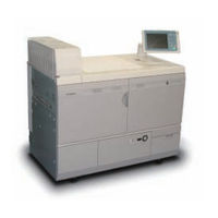
Canon imagePRESS 1135 Service Manual (1603 pages)
Brand:
Canon
| Category:
Printer
| Size: 59.88 MB
Table of Contents
4
Table of Contents
12
Safety Precautions
13
Laser Safety
13
Handling of Laser System
14
Turn Power Switch
14
Points to Note about Turning Off the Main Power Switch
15
Safety of Toner
15
About Toner
15
Toner On Clothing or Skin
15
Notes When Handling a Lithium Battery
15
Notes before It Works Serving
16
1 Product Overview
16
Product Lineup
17
Main Unit
17
Pickup and Delivery System Options
20
Image Scanning System Options
21
Function Extension System Option
23
Features
23
Product Features
23
Service Features
23
SITUATION Mode
24
Version Upgrade Workability Up
25
Use of New Connectors
26
Main Unit Specifications
27
Power Supply Specifications
28
Weight and Size
33
Productivity (Printing Speed)
34
Paper Types
42
External and Internal Views
42
External View
43
Sectional View
44
Operation
44
Power Supply Switches
45
Control Panel
46
Additional Function Mode (Mode for User Administrator)
49
2 Technology
49
Basic Configuration
50
Functional Configuration
52
Controller System
52
Overview
55
Controls
70
Service Operation
71
Laser Control System
71
Overview
73
Various Controls
78
Work of Service
79
Image Formation System
79
Overview
85
Various Types of Control
107
Servicing Work
112
Fixing System
112
Overview
116
Various Types of Control
129
Servicing Work
130
Pickup / Feed System
130
Overview
137
Pick-Up Area Control/Function
158
Pre-Registration Area Control/Function
163
Active Registration Area Control / Function
173
Pre-Fixing Feed Area
176
Buffer Delivery Area Control/Function
181
Duplexing Area Function/Control
183
Escape Area Control/Function
184
Servicing Work
188
Meap
188
Checking the Operating Environment
191
Setting Up the Network
192
Login to SMS
194
Setting the Method to Login to SMS
197
Checking Application List
198
Starting and Stopping a MEAP Application
199
Checking the Platform Information
200
MEAP Specifications
202
Checking the System Information of a MEAP Application with SMS
203
Printing the System Information of a MEAP Application
203
Reference (Application System Information)
204
Installing an Application
206
Adding a License File
207
Disabling a License File (Suspending a License)
209
Downloading/Removing an Invalidated License File
210
Reusable License
211
License for Forwarding
213
Uninstalling an Application
214
Login Service
220
Changing Login Services
221
Initializing the Password
221
Creating a Backup for MEAP Application Area, Formatting the Hard Disk, Restoring the MEAP Application Area with the Backup, Using the SST (Service Support Tool)
222
Replacing the Hard Disk Drive
223
MEAP Safe Mode
224
Setting HTTP Port for MEAP Application (Level 2)
226
Reference Material
228
Option for Exclusive Individual Measure
230
Em Controller-E1
230
Overview
231
Settings Procedures
235
Faq
237
Troubleshooting Guide
241
Service Cautions
242
3 Periodical Service
242
Periodical Service Item
265
4 Parts Replacement and Cleaning
265
List of Parts
266
List of External / Internal Cover
269
List of Main Unit
276
List of Clutch / Solenoid
278
List of Motor
286
Fan
293
List of Sensor
302
Heater / Other
306
Switch
308
Pcb
318
External Cover
318
Open the Front Left Cover and the Front Right Cover
318
Open Front Left Cover
319
Removing Rear Left Cover
319
Removing Rear Right Cover
320
Removing Rear Lower Cover
320
Pulling Out Waste Toner Case Unit
321
Opening Controller Box Unit
322
Main Unit
322
Removing Laser Scanner Unit
332
Removing Pre Exposure LED (1)
334
Removing Pre-Exposure LED (2)
335
Removing Process Unit Cover
336
Pulling Out Process Unit
342
Removing Supply Pipe Unit
347
Pulling Out ITB Unit
350
Removing Secondary Transfer Outer Unit
352
Removing Patch Sensor Unit
355
Removing Registration Unit
358
Removing Registration Front Guide Unit
360
Caution about the Disassembly of Fixing Assembly
361
Caution about the Thermistor/Thermo Switch
362
Open Fixing Upper Unit
364
Open Inner Delivery Unit
365
Removing Fixing Main Unit
367
Removing Fixing Pressure Unit
374
Removing Fixing Roller Unit
379
Installing the Fixing Heater
380
Removing Pressure Roller Unit
383
Installing the Pressure Heater
384
Pulling Out Fixing Feed Unit
385
Removing Feed Belt Unit
388
Removing Pickup Unit
389
Removing Delivery Outer Cover Unit
390
Removing Delivery Inner Cover Unit
392
Removing Delivery Guide Unit (Upper)
393
Removing Pressure Decurler 2
397
Pulling Out Buffer Delivery Unit
399
Removing Buffer Delivery Upper Unit
403
Removing Reversal Unit
405
Removing Control Panel Unit
407
Removing Hopper Unit
412
Pulling Out Paper Deck
413
Removing Paper Deck
416
Removing the Deck Lifter Motor Unit
419
Removing Air Pickup Heater
421
Periodic Replacing Parts, Durable Parts, Cleaning Parts
421
Removing Dustproof Glass
422
Removing Primary Charging Assembly
424
Points to Note When Installing the Primary Charging Assembly
425
Removing Primary Charging Wire (Right) Pad Holder
427
Removing Primary Charging Wire (Right) Slider
429
Replacing Primary Charging Wire (Right)
433
Removing Primary Charging Wire (Left) Pad Holder
435
Removing Primary Charging Wire (Left) Slider
437
Replacing Primary Charging Wire (Left)
441
Removing Pre-Primary Transfer Charging Assembly
442
Removing Pre-Primary Transfer Charging Wire Pad Holder
444
Removing Pre-Primary Transfer Charging Wire Slider
445
Replacing Pre-Primary Transfer Charging Wire
449
Removing Developing Assembly
452
Removing Developing Sleeve Unit
457
Cleaning Procedure During Developing Assembly Replacement
459
Removing Drum Cleaning Unit
462
Removing Drum Cleaning Blade
463
Installing the Drum Cleaning Blade
468
Caution When Handling Photosensitive Drum Unit
469
Removing Photosensitive Drum Unit
471
Operation After Replacing the Photosensitive Drum Unit
472
Cleaning Pre-Primary Transfer Exposure Unit and Cleaning Pre-Exposure Unit
474
Cleaning Procedure of Filters
478
Removing Primary Transfer Roller
481
Removing Secondary Transfer Inner Roller
483
Removing ITB
487
ITB Secondary Transfer Inlet Upper Guide
491
Removing ITB Cleaning Unit
495
Removing ITB Cleaning Blade
496
Installing the ITB Cleaning Blade
501
Cleaning Procedure During ITB Replacement
506
Cleaning Procedure of ITB Back Side
507
Cleaning Fixing Feed Unit (2 Hundred Thousand Sheet)
512
Cleaning Fixing Feed Unit (5 Hundred Thousand Sheet)
521
Cleaning Duplexing Unit
522
Removing Secondary Transfer Outer Roller
525
Cleaning Pre-Registration Unit (2 Hundred Thousand Sheet)
526
Cleaning Pre-Registration Unit (5 Hundred Thousand Sheet)
537
Removing Fixing Web Unit
538
Removing Fixing Web
542
Removing Fixing Web Roller
543
Removing Fixing Roller
543
Removing Fixing Roller Bearing
544
Removing Fixing Roller Insulating Bush
545
Removing Fixing Roller Main Thermistor
548
Removing Fixing Roller Sub Thermistor
549
Removing Fixing Roller Thermo Switch
549
Removing Pressure Roller
550
Removing Pressure Roller Bearing
550
Removing Pressure Roller Insulating Bush
551
Remove Pressure Roller Main Thermistor
554
Removing Pressure Roller Sub Thermistor
554
Removing Pressure Roller Thermo Switch
555
Removing Fixing Refresh Roller
558
Removing External Heat Roller Unit
559
Removing External Heat Cleaning Roller
560
Removing External Heat Roller (Upper), External Heat Insulating Bushing (Upper), and External Heat Bearing (Upper)
563
Removing External Heat Roller (Lower), External Heat Insulating Bushing (Lower) and External Heat Bearing (Lower)
566
Removing External Main Thermistor (Upper), External Heat Sub Thermistor (Upper), External Heat Main Thermistor (Lower) and External Heat Sub Thermistor (Lower)
570
Removing External Heat Roller Upper/Lower Thermo Switch
571
Removing Fixing Roller Separation Claw
572
Removing Pressure Roller Separation Claw Unit
574
Removing Pressure Roller Separation Claw
575
Cleaning Fixing Assembly
578
Cleaning Reverse Unit
580
Remove Delivery Decurler Belt Unit 1
582
Removing Delivery Decurler Belt 1
585
Remove Delivery Decurler Belt Unit 2
587
Removing Delivery Decurler Belt 2
590
Cleaning Buffer Delivery Unit (2 Hundred Thousand Sheet)
591
Cleaning Buffer Delivery Unit (5 Hundred Thousand Sheet)
596
Removing Duplex Decurler Belt Unit
598
Removing Duplexing Decurler Belt
601
Removing Deck Separation Pad (Right) / Deck Separation Pad (Left)
602
Removing Deck Pickup Solenoid
604
Cleaning Pickup Unit and Deck Unit
605
Removing the Paper Dust Cleaning Brush
611
Removing Fixing Ozone Filter
612
Removing Primary Charging Ozone Filter
613
Removing Fixing Toner Filter
614
Removing Primary Charging Toner Filter
615
Removing Developing Toner Filter
616
Pcb
616
Removing the Main Controller PCB 1 Unit
617
Removing Main Controller PCB 2
618
Removing DC Controller PCB
620
Removing Hard Disc
621
Removing Developing High-Voltage PCB
622
Removing the Pickup Feed Driver PCB
623
Removing Primary Transfer High-Voltage PCB
624
Removing Primary Pre-Transfer Charging High-Voltage PCB
625
Removing Primary Charging High-Voltage PCB
626
Removing Secondary Transfer High-Voltage PCB
627
Removing AC Driver PCB
628
Removing the Fixing AC Driver PCB
630
Removing 12V Power PCB Unit
632
Removing 24V Power PCB Unit
633
Removing 24V Power PCB
635
Removing 24V Power PCB1
637
Removing 24V Power PCB 2
638
Removing 24V Power PCB 3
639
Removing All-Night Power PCB
640
Removing Leakage Breaker Unit
641
Removing Leakage Breaker 15A
642
Removing Leakage Breaker 20A
643
Removing Registration Duplex Driver PCB
644
Removing Secondary Transfer Static Eliminator PCB
645
Removing the ITB Driver PCB
646
Removing Fixing High-Voltage PCB
647
Removing Fixing Main Driver PCB
648
Removing Potential Sensor PCB
649
Removing Developing Dirvere PCB
650
Removing Power Relay PCB
652
Removing the Deck Driver PCB
653
Data to Be Handled By SRAM
653
The Kind of Data to Handle
655
5 Adjustment
655
Overview
655
When Replacing Parts
657
Controller System
658
Laser Control System
658
Imaging System
660
Pickup / Feed System
663
External Auxiliary System
664
Major Adjustment
664
Primary Charging Assembly
665
Image Location Adjustment
668
6 Troubleshooting
668
Making Initial Checks
669
List of Initial Check Items
670
Test Print
670
Overview
670
Selecting Test Print TYPE
671
How to Check Test Print
672
Troubleshooting Items
672
List of Troubleshooting Items
673
Image Faults
673
Random Black Belt / Horizontal Lines (Halftone)
674
Splash On Characters (Coated Paper)
675
Dark Image (Edge On "13 X "19 Inch Paper)
676
Splash (Trailing Edge of Halftone)
677
Density Loss Due to Excessive Transfer (2Nd Side)
678
Mottled Image (2Nd-Side)
679
Unfocused Image (Margin)
680
Separation Claw Trace (Solid Image, 1St Side of 2-Sided Print)
681
Horizontal / Vertical Lines (Due to Refresh Roller)
682
Points to Note When Using the Pre-Printed Paper
685
Malfunction
685
Front Cover Distortion Correction
686
Front Cover Tilt Correction
687
Feeding Failure
687
Multiple Feeding
696
Remedy against 0112 Jam
700
Version Upgrade
700
Outline
704
Making Preparations
711
Formatting HDD
713
Downloading System Software
722
Uploading and Downloading Backup Data
725
Version Upgrade Using USB
733
Pickup Position Code
734
Outline
736
Pickup Size
736
Outline
737
Error Code
737
Error Code Details
895
Jam Code
895
Jam Type
895
Imagepress 1135+/1125+/1110
899
Color Image Reader-L1 (Reader + DADF)
900
POD Deck-C1 / Secondary POD Deck-C1
904
Multi Drawer Document Insertion Unit-A1
906
Professional Puncher-B1 / Professional Puncher
906
Integration Unit-A1
908
High Capacity Stacker-E1
910
Perfect Binder-C1
911
Paper Folding Unit-F1
913
Finisher-Ak1 / Saddle Finisher-Ak2
914
Booklet Trimmer-D1 / Two-Knife Booklet Trimmer-A1
916
Document Insertion Unit-F1
918
Side Paper Deck-Af1 (Multi Drawer)
919
Finisher-Ag1 / Saddle Finisher-Ag2
920
Alarm Code
920
Alarm Code Details
944
8 Service Mode
944
Overview
945
Points to Note When Using Service Mode
945
Service Mode Menu
946
Service Mode Item Explanations
947
I/O Information Enhancement
947
Display of Error Code/Alarm Code Description
948
COPIER > OPTION > BODY, Item Segmentation
948
Security Features
949
Switching Screen (Level 1 < - > 2)
950
Language Switch
950
Back-Up of Service Mode
951
The Data Output of the Service Data Print
955
Copier
955
DISPLAY (Status Display Mode)
1104
ADJUST (Adjustment Mode)
1155
FUNCTION (Operation / Inspection Mode)
1173
OPTION (Mechanical Specifications Setting Mode)
1266
TEST (Test Print Mode)
1269
Counter
1365
Feeder
1365
Display
1366
Adjust
1367
Function
1370
Sorter
1370
Adjust
1387
Function
1400
Board
1401
Situation Mode
1401
Troubleshooting
1409
Parts Replacement
1415
Major Adjustment
1418
9 Installation
1419
How to Check This Installation Procedure
1419
When Using the Contents (Parts Included in the Package)
1419
Symbols in the Illustration
1420
Order to Install Options
1420
Checking before Installation
1420
Checking Power Supply
1421
Checking Installation Environment
1421
Checking Installation Site
1421
Checking Installation Space
1423
Points to Note at Installation
1424
Unpacking
1426
Checking the Contents
1428
Installation
1428
Installing the Host Machine
1429
Before Installing the Host Machine
1430
Removing the Toner Blocking Material and the Package Material of Fixing Feed Unit
1437
Removing the Transportation Packing Member of the Process Unit --9-20
1440
Installing the Developing Assembly
1449
Removing the Transportation Packing Member of the ITB Unit
1452
Removing the Packing Member of the Waste Toner Container
1452
Removing the Packing Member of the Deck
1454
Installing the Cleaning Tool
1456
Preparing Connection of the Main Power Supply
1457
Initial Installation Service Mode 1
1459
Setting the Toner Container
1461
Attaching the Label
1462
Moving the Control Panel Arm
1464
Fixing the Top Board
1465
Setting Paper
1467
Setting Paper Size
1468
Initial Installation Service Mode 2
1469
Checking Image Margin
1470
Image Position Adjustment
1473
Checking Network Connection
1474
Troubleshooting of Network
1475
Other Installations
1476
Label Position
1479
Operation When Moving the Machine
1480
Card Reader-C1
1480
Point to Note about Installation
1480
Checking Contents
1482
Turning OFF Host Machine
1482
Installation Procedure
1491
Installation Procedure Used in the Imageware Accounting Manager (Will Be Called As Iwam) Environment
1492
Imagepress Printer Kit-A1
1492
Checking Contents
1492
Turning OFF Host Machine
1493
Installation Procedure
1494
Post-Installation Check
1494
To Obtain and Register License Key
1495
Cassete Heater-32
1495
Checking the Contents
1495
Check Items When Turning OFF the Main Power
1496
Installation Procedure (Connecting to Host Machine)
1503
Installation Procedure (Connecting to POD Deck / Secondary POD Deck)
1510
Reader Heater Kit-G1
1510
Checking Contents
1510
Turning Off Host Machine
1511
Installation Procedure
1516
Tab Feeding Attachment-E1
1516
Checking Contents
1517
Installation Procedure
1518
Ipsec Board-B1/B2
1518
Pre-Installation Check
1518
Checking Contents
1518
Turning OFF Host Machine
1519
Installation Procedure
1520
Post-Installation Check
1521
Voice Guidance Kit-E1
1521
Checking before Installation
1522
Checking Contents
1523
Turning OFF Host Machine
1523
Installation Procedure
1531
Checking After Installation
1532
When about to Use
1533
Expansion Bus-F1/F2
1533
Checking Contents
1533
Turning OFF Host Machine
1534
Installation Procedure
1536
System Upgrade RAM-B1
1536
Checking Contents
1536
Turning OFF Host Machine
1537
Installation Procedure
1538
Post-Installation Check
1539
Removable Hard Disk Kit-Aa1
1539
Points to Note about Installation
1540
Checking the Contents
1541
Power OFF of the Host Machine
1541
Installation Procedure
1555
Appendix
1555
Service Tools
1556
Special Tools
1559
Solvents and Oils
1560
General Circuit Diagram
1560
General Circuit Diagram (1/34)
1561
General Circuit Diagram (2/34)
1562
General Circuit Diagram (3/34)
1563
General Circuit Diagram (4/34)
1564
General Circuit Diagram (5/34)
1565
General Circuit Diagram (6/34)
1566
General Circuit Diagram (7/34)
1567
General Circuit Diagram (8/34)
1568
General Circuit Diagram (9/34)
1569
General Circuit Diagram (10/34)
1570
General Circuit Diagram (11/34)
1571
General Circuit Diagram (12/34)
1572
General Circuit Diagram (13/34)
1573
General Circuit Diagram (14/34)
1574
General Circuit Diagram (15/34)
1575
General Circuit Diagram (16/34)
1576
General Circuit Diagram (17/34)
1577
General Circuit Diagram (18/34)
1578
General Circuit Diagram (19/34)
1579
General Circuit Diagram (20/34)
1580
General Circuit Diagram (21/34)
1581
General Circuit Diagram (22/34)
1582
General Circuit Diagram (23/34)
1583
General Circuit Diagram (24/34)
1584
General Circuit Diagram (25/34)
1585
General Circuit Diagram (26/34)
1586
General Circuit Diagram (27/34)
1587
General Circuit Diagram (28/34)
1588
General Circuit Diagram (29/34)
1589
General Circuit Diagram (30/34)
1590
General Circuit Diagram (31/34)
1591
General Circuit Diagram (32/34)
1592
General Circuit Diagram (33/34)
1593
General Circuit Diagram (34/34)
1594
General Timing Chart
1594
General Timing Chart (1/2)
1595
General Timing Chart (2/2)
1596
Operator Maintenance
1596
Outline
1596
Operator Maintenance Mode
1598
Maintenance
1602
Backup Data
Advertisement
Canon imagePRESS 1135 Media Manual (2 pages)
B & W Copier
Brand:
Canon
| Category:
Copier
| Size: 0.14 MB
Share and save
Advertisement
Related Products
Canon CLC 1130
Canon CLC 1150
Canon CLC 1120
Canon 1160
Canon 1180
Canon 1140
Canon imagePRESS 1110
Canon imagePRESS 1125
Canon 1000S
Canon imageRUNNER 1435
Canon Categories
Printer
Digital Camera
All in One Printer
Camcorder
Scanner
More Canon Manuals
×
Login
Sign In
OR
Sign in with Facebook
Sign in with Google
×
Upload manual
Upload from disk
Upload from URL