Sign In
Upload
Manuals
Brands
BONFIGLIOLI Manuals
Inverter
ACTIVE Cube ACU 201-09
BONFIGLIOLI ACTIVE Cube ACU 201-09 Manuals
Manuals and User Guides for BONFIGLIOLI ACTIVE Cube ACU 201-09. We have
1
BONFIGLIOLI ACTIVE Cube ACU 201-09 manual available for free PDF download: Operating Instructions Manual
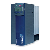
BONFIGLIOLI ACTIVE Cube ACU 201-09 Operating Instructions Manual (292 pages)
Frequency inverter 230 V / 400 V 0.25 kW ... 132 kW
Brand:
BONFIGLIOLI
| Category:
Inverter
| Size: 14 MB
Table of Contents
Table of Contents
3
1 General Information about the Documentation
10
Instruction Manuals
10
This Document
12
Warranty and Liability
12
Obligation
13
Copyright
13
Storage
13
2 General Safety Instructions and Information on Use
14
Terminology
14
Designated Use
15
Misuse
15
Explosion Protection
15
Residual Risks
16
Safety and Warning Signs at Frequency Inverter
16
Warning Information and Symbols Used in the User Manual
17
Hazard Classes
17
Hazard Symbols
17
Prohibition Signs
17
Personal Safety Equipment
18
Recycling
18
Grounding Symbol
18
ESD Symbol
18
Information Signs
18
Directives and Guidelines to be Adhered to by the Operator
19
Operator's General Plant Documentation
19
Operator's/Operating Staff's Responsibilities
19
Selection and Qualification of Staff
19
General Work Safety
19
Organizational Measures
20
General
20
Use in Combination with Third-Party Products
20
Transport and Storage
20
Handling and Installation
20
Electrical Connections
20
The Five Safety Rules
21
Safe Operation
21
Maintenance and Service/Troubleshooting
22
Final Decommissioning
22
Safety Instructions on Function „Safe Torque Off" (STO)
23
3 Scope of Supply
25
ACU 201 (up to 3.0 Kw) and 401 (up to 4.0 Kw)
25
ACU 201 (4.0 to 9.2 Kw) and 401 (5.5 to 15.0 Kw)
26
ACU 401 (18.5 to 30.0 Kw)
27
ACU 401 (37.0 to 65.0 Kw)
28
ACU 401 (75.0 to 132.0 Kw)
29
4 Technical Data
30
General Technical Data
30
Technical Data - Control Electronic Equipment
31
ACU 201 (0.25 to 1.1 Kw, 230 V)
32
ACU 201 (1.5 to 3.0 Kw, 230 V)
33
ACU 201 (4.0 to 9.2 Kw, 230 V)
34
ACU 401 (0.25 to 1.5 Kw, 400 V)
35
ACU 401 (1.85 to 4.0 Kw, 400 V)
36
ACU 401 (5.5 to 15.0 Kw, 400 V)
37
ACU 401 (18.5 to 30.0 Kw, 400 V)
38
ACU 401 (37.0 to 65.0 Kw, 400 V)
39
ACU 401 (75.0 to 132.0 Kw, 400 V)
40
Operation Diagrams
41
5 Mechanical Installation
42
ACU 201 (up to 3.0 Kw) and 401 (up to 4.0 KW)
43
ACU 201 (4.0 to 9.2 Kw) and 401 (5.5 to 15.0 Kw)
44
ACU 401 (18.5 to 30.0 Kw)
45
ACU 401 (37.0 to 65.0 Kw)
46
ACU 401 (75.0 to 132.0 Kw)
47
6 Electrical Installation
48
EMC Information
50
Block Diagram
52
Optional Components
53
Connection of Unit
54
Dimensioning of Conductor Cross-Section
54
Typical Cross-Sections
54
Mains Connection
56
Motor Connection
56
Length of Motor Cables, Without Filter
57
Motor Cable Length, with Output Filter Du/Dt
57
Motor Cable Length, with Sinus Filter
57
Group Drive
58
Speed Sensor Connection
58
Connection of a Brake Resistor
59
Connection of Types
60
ACU 201 (up to 3.0 Kw) and 401 (up to 4.0 Kw)
60
ACU 201 (4.0 to 9.2 Kw) and 401 (5.5 to 15.0 Kw)
62
ACU 401 (18.5 to 30.0 Kw)
64
ACU 401 (37.0 to 65.0 Kw)
66
ACU 401 (75.0 to 132.0 Kw)
68
Control Terminals
70
External DC 24 V Power Supply
72
Relay Output
72
Motor Thermo-Contact
73
Control Terminals - Connection Diagrams of Configurations
73
Configurations Overview
74
Configuration 110 - Sensorless Control
75
Configuration 111 - Sensorless Control with Technology Controller
75
Configuration 410 - Sensorless Field-Oriented Control
76
Configuration 411 - Sensorless Field-Oriented Control with Technology Controller
77
Configuration 430 - Sensorless FOC, Speed and Torque Controlled
78
Configuration 210 - Field-Oriented Control, Speed Controlled
79
Configuration 211 - Field-Oriented Control with Technology Controller
80
Configuration 230 - Field-Orientated Control, Speed and Torque Controlled
80
Configuration 510 - FOC of Synchronous Machine, Speed Controlled
81
Configuration 610 - Sensorless FOC of Synchronous Machine, Speed Controlled
83
Configuration 611 - Sensorless FOC of a Synchronous Machine with Technology Controller
84
Configuration 630 - Sensorless FOC of a Synchronous Machine, Speed and Torque Controlled
85
Installation Notes According to Ul508C
86
7 Control Unit KP500
87
Menu Structure
88
Main Menu
88
Actual Value Menu (VAL)
89
Parameter Menu (PARA)
90
Copy Menu (CPY)
91
Reading the Stored Information
91
Menu Structure
92
Selecting the Source
92
Selecting the Destination
93
Copy Operation
93
Error Messages
94
Reading Data from Control Unit
95
Activation
95
Data Transfer
96
Resetting to Normal Operation
97
Control Menu (CTRL)
97
Controlling the Motor Via the Control Unit
98
8 Commissioning of the Frequency Inverter
101
Switching on Mains Voltage
101
Setup Using the Control Unit
101
Configuration
102
Data Set
104
Motor Type
104
Machine Data
105
Plausibility Check
106
Parameter Identification
107
Status Messages During Commissioning (SS
108
Warnings During Commissioning (SA
108
Error Messages During Commissioning (SF
110
Application Data
111
Acceleration and Deceleration
111
Set Points at Multi-Functional Input
111
Quitting Commissioning
112
Selection of an Actual Value for Display
112
Check Direction of Rotation
113
Speed Sensor
114
Speed Sensor 1
115
Speed Sensor 2
115
Set-Up Via the Communication Interface
116
9 Inverter Data
118
Serial Number
118
Optional Modules
118
Inverter Software Version
118
Set Password
118
Control Level
119
User Name
119
Configuration
119
Language
122
Programming
122
10 Machine Data
123
Rated Motor Parameters
123
Further Motor Parameters
124
Stator Resistance
124
Leakage Coefficient
124
Magnetizing Current
125
Rated Slip Correction Factor
125
Voltage Constant
126
Stator Inductance
126
Peak Current
126
Change Sense of Rotation
127
Internal Values
127
Speed Sensor 1
128
Operation Mode Speed Sensor 1
128
Division Marks, Speed Sensor 1
130
Gear Factor Speed Sensor 1
131
Filter Time Constant Speed Sensor 1
131
Sensor Evaluation
132
11 System Data
133
Actual System Value
133
Volume Flow and Pressure
133
12 Operational Behavior
134
Starting Behavior
134
Starting Behavior of Sensorless Control System
134
Starting Current
136
Frequency Limit
136
Brake Release Time
136
Flux Formation
137
Stopping Behavior
138
Switch-Off Threshold
140
Holding Time
140
Direct Current Brake
140
Auto Start
141
Search Run
142
Positioning
144
Reference Positioning
144
Axle Positioning
147
13 Error and Warning Behavior
149
Overload Ixt
150
Temperature
150
Controller Status
151
IDC Compensation Limit
151
Frequency Switch-Off Limit
152
Motor Temperature
152
Phase Failure
153
Automatic Error Acknowledgment
153
14 Reference Values
154
Frequency Limits
154
Slip Frequency
154
Percentage Value Limits
154
Frequency Reference Channel
154
Block Diagram
156
Reference Percentage Channel
158
Block Diagram
159
Fixed Reference Values
161
Fixed Frequencies
161
JOG Frequency
162
Fixed Percentages
162
Frequency Ramps
163
Percentage Value Ramps
166
Block Frequencies
166
Motor Potentiometer
167
Motorpoti (MP)
168
Motorpoti (KP)
168
Controlling the Motor Via the Control Unit
169
PWM-/Repetition Frequency Input
170
15 Control Inputs and Outputs
172
Multi-Function Input MFI1
172
Analog Input MFI1A
172
Characteristic
172
Scaling
174
Tolerance Band and Hysteresis
174
Filter Time Constant
175
Error and Warning Behavior
176
Multi-Function Output MFO1
177
Analog Output MFO1A
177
Output Characteristic
178
Frequency Output MFO1F
179
Scaling
179
Digital Outputs
180
Digital Signal
183
Setting Frequency
184
Reference Value Reached
185
Flux Forming Finished
186
Brake Release
186
Current Limitation
186
External Fan
186
Warning Mask
187
Application Warning Mask
190
Digital Inputs
191
Start Command
196
3-Wire Control
196
Error Acknowledgment
197
Timer
197
Thermo Contact
197
N-/M Control Change-Over
197
Data Set Change-Over
198
Fixed Value Change-Over
199
Motor Potentiometer
199
Handshake Traverse Function
200
User Warning
200
External Error
200
Function Modules
201
Timer
201
Timer - Time Constant
202
Comparator
204
Function Table
205
Multiplexer/Demultiplexer
206
16 F-Characteristic
208
Dynamic Voltage Pre-Control
209
17 Control Functions
210
Intelligent Current Limits
210
Voltage Controller
211
Technology Controller
216
Functions of Sensorless Control
226
Slip Compensation
226
Current Limit Value Controller
226
Functions of Field-Orientated Control
227
Current Controller
227
Extended Current Controller
229
Torque Controller
229
Torque Reference
230
Upper and Lower Limit of the Frequency in Torque Control
230
Limit Value Sources
231
Switching over between Speed Control and Torque Control
231
Speed Controller
232
Limitation of Speed Controller
234
Limit Value Sources
235
Integral Time Speed Synchronization
236
Acceleration Pre-Control
236
Field Controller
237
Limitation of Field Controller
238
Modulation Controller
239
Limitation of Modulation Controller
239
18 Special Functions
240
Pulse Width Modulation
240
Fan
241
Bus Controller
241
Brake Chopper and Brake Resistance
243
Dimensioning of Brake Resistor
244
Motor Protection
245
Motor Protection Switch
245
Motor Protection by I2T- Monitoring
248
V-Belt Monitoring
250
Functions of Field-Orientated Control
251
Motor Chopper
251
Temperature Adjustment
252
Speed Sensor Monitoring
253
Traverse Function
254
Converter Profibus From/To Internal Notation
256
19 Actual Values
257
Actual Values of the Frequency Inverter
257
STO Status
259
Actual Values of the Machine
260
Actual Value Memory
261
Actual Values of the System
262
Actual System Value
262
Volume Flow and Pressure
263
20 Error Protocol
264
Error List
264
Error Messages
264
Error Environment
269
21 Operational and Error Diagnosis
271
Status Display
271
Status of Digital Signals
271
Controller Status
272
Warning Status and Warning Status Application
273
22 Parameter List
275
Actual Value Menu (VAL)
275
Parameter Menu (PARA)
278
Index
287
Functions of the Control Terminals (Table)
289
Advertisement
Advertisement
Related Products
BONFIGLIOLI ACTIVE Cube ACU 201-01
BONFIGLIOLI ACTIVE Cube ACU 201-03
BONFIGLIOLI ACTIVE Cube ACU 201-05
BONFIGLIOLI ACTIVE Cube ACU 201-07
BONFIGLIOLI ACTIVE Cube ACU 201-11
BONFIGLIOLI ACTIVE Cube ACU 201-13
BONFIGLIOLI ACTIVE Cube ACU 201-18
BONFIGLIOLI ACTIVE Cube ACU 201-19
BONFIGLIOLI ACTIVE Cube ACU 201-21
BONFIGLIOLI ACTIVE Cube ACU 201-22
BONFIGLIOLI Categories
DC Drives
Engine
Inverter
Industrial Equipment
Controller
More BONFIGLIOLI Manuals
Login
Sign In
OR
Sign in with Facebook
Sign in with Google
Upload manual
Upload from disk
Upload from URL