
Subscribe to Our Youtube Channel
Related Manuals for GeoVision GV-IP Speed


Summary of Contents for GeoVision GV-IP Speed
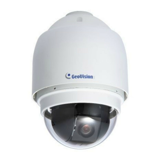
- Page 1 GV-IP Speed Dome User's Manual User's Manual Firmware V1.02 Firmware V1.02 Before attempting to connect or operate this product, ISDV102-A please read these instructions carefully and save this manual for future use.
- Page 2 GeoVision. Every effort has been made to ensure that the information in this manual is accurate. GeoVision, Inc. makes no expressed or implied warranty of any kind and assumes no responsibility for errors or omissions. No liability is assumed for incidental or consequential damages arising from the use of the information or products contained herein.
- Page 3 Preface Welcome to the GV-IP Speed Dome User’s Manual. There are two types of the GV-IP Speed Dome, Indoor and Outdoor. Each type also has a series of models designed to meet different needs: Application Model Firmware Version GV-SD010-18X Indoor...
-
Page 4: Table Of Contents
1.6 Communication Switch ................... 10 1.7 22-Pin Data Cable ....................11 1.8 Optional Accessories ....................13 Chapter 2 Installing the GV-IP Speed Dome ............16 2.1 Ceiling Mount......................17 2.1.1 Surface Mount (Indoor Use Only) ...............17 2.1.2 Flush Mount (Indoor Use Only)..............20 2.1.3 Straight Tube Mount (Indoor Type) .............23... - Page 5 3.2.3 Snapshot of a Live Video ................45 3.2.4 Video Recording ..................46 3.2.5 Wide Angle Dewarping ................46 3.2.6 Picture-in-Picture and Picture-and-Picture View.........47 3.2.7 Alarm Notification..................49 3.2.8 Video and Audio Configuration ..............50 3.2.9 Remote Configuration.................50 3.2.10 Camera Name Display................50 3.2.11 Image Enhancement .................51 3.2.12 PTZ Control ....................51 3.2.13 Visual PTZ ....................52 3.2.14 I/O Control ....................53...
- Page 6 8.1 Center V2 ......................123 8.2 VSM........................125 8.3 Dispatch Server ....................126 Chapter 9 Mobile Phone Connection..............127 9.1 PDA ........................129 9.1.1 Installing GV-GView V2................129 9.1.2 Activating the GV-GView Function............129 9.1.3 Connecting to GV-IP Speed Dome ............130 9.2 Windows Smartphone ..................131...
- Page 7 9.3.4 Quick Connection ..................135 9.4 3G Mobile Phone....................136 9.4.1 Activating the 3G Mobile Phone Function..........136 9.4.2 Connecting to the GV-IP Speed Dome .............136 9.5 Android Smartphone..................... 138 9.5.1 Connecting to GV-IP Speed Dome ............138 9.5.2 Accessing Live View .................140 9.6 iPhone, iPod Touch and iPad ................
-
Page 8: Regulatory Notices
Regulatory Notices FCC Notice This equipment has been tested and found to comply with the limits for a Class A digital device, pursuant to part 15 of the FCC Rules. These limits are designed to provide reasonable protection against harmful interference when the equipment is operated in a commercial environment. -
Page 9: Note For Connecting To Gv-System
Note for Connecting to GV-System The GV-IP Speed Dome is designed to work with and record on GV-System, a hybrid or digital video management system. Once the GV-IP Speed Dome is connected to the GV-System, the resolution set on the GV-System will override the resolution set on the GV-IP Speed Dome’s Web interface. -
Page 11: Chapter 1 Introduction
Introduction Chapter 1 Introduction 1.1 Overview To meet different needs, the GV-IP Speed Dome is offered in two types: indoor and outdoor. Through both web-based configurations, it is easy to configure and manage the GV-IP Speed Dome. The GV-IP Speed Dome provides variable pan/tilt speeds ranging from a fast patrol of 400°... -
Page 12: System Requirements
1.2 System Requirements To access GV-IP Speed Dome functions through Web browser, ensure your PC is in good network connection and use one of the following web browsers: • Microsoft Internet Explorer 7.x or later • Google Chrome • Mozilla Firefox •... -
Page 13: Packing List
Introduction 1.3 Packing List 1.3.1 GV-IP Speed Dome of Indoor Type Dome Body Hard Ceiling Mount and Decoration Ring Optical Cover Data Cable for Power Supply, Video, Audio and Alarm (Length: 1.3 m / 4.27 ft ) Power Adaptor GV-IP Speed Dome User’s Manual... -
Page 14: Gv-Ip Speed Dome Of Outdoor Type
1.3.2 GV-IP Speed Dome of Outdoor Type Dome Body with Outdoor Mount Kit (which is attached to the Dome) Optical Cover Data Cable for Power Supply, Video, Audio and Alarm (Length: 5 m / 16.4 ft ) Lubricant M3 Standard Screw (x 1), M3 Security Screw (x1),... -
Page 15: Functional Panel
1.4.1 GV-IP Speed Dome of Indoor Type Figure 1-1 No. Name Function Resets the GV-IP Speed Dome and keeps all Reset current configurations. Restores all the settings, except PTZ settings, to Default the factory default values. For details see 6.3 Restoring to Factory Default Settings. -
Page 16: Gv-Ip Speed Dome Of Outdoor Type
1.4.2 GV-IP Speed Dome of Outdoor Type Figure 1-2 No. Name Function Reset Resets all configurations of GV-IP Speed Dome. Restores all the settings, except PTZ settings, to Default the factory default values. For details see 6.3 Restoring to Factory Default Settings. -
Page 17: Preparing For Outdoor-Type Dome Setup
Introduction 1.5 Preparing for Outdoor-Type Dome Setup The GV-IP Speed Dome of outdoor type is equipped with the sunshield housing. Follow the steps below to complete the housing installation. 1. Unpack the package and take out the GV-IP Speed Dome. - Page 18 3. Remove the protective cover and PE sheet. Figure 1-6 4. Lightly rub a thin layer of lubricant onto the waterproof rubber of the Dome cover before attaching the cover to the body. Figure 1-7 Note that the tiny protrusion on the cover must align with one of the four holes on the Dome body.
- Page 19 Introduction 5. Gently press down the Dome cover with two hands on the side of it. Figure 1-9 DO NOT press the cover as shown in the figure. This might damage the Dome. Figure 1-10 6. Screw the Dome cover and body together. Figure 1-11...
-
Page 20: Communication Switch
Communication Switch You can find the Communication Switch below in both indoor and outdoor types of GV-IP Speed Domes. Figure 1-12 SW 1 SW 2 Not Functional SW 3 SW 4 Default SW 5 Not Functional SW 6 SW5 is used to restore all the PTZ settings to original default values. Follow the steps below to restore default PTZ values: 1. -
Page 21: 22-Pin Data Cable
Introduction 1.7 22-Pin Data Cable With the 22-pin Data Cable, you can connect the power, microphone, speaker, TV monitor and I/O devices to the GV-IP Speed Dome. The Data Cable is illustrated as below. I/O Wires Audio Input 22-Pin Data Cable... - Page 22 Wire Definition for Power Input Connect the three wires of Power Adaptor to the 3-pin terminal block of power input, based on the following wire assignments. Figure 1-14 Wire Assignments for 220 V Power Adaptor Wires of 3-Pin Terminal Block Wires of Power Adaptor Blue Yellow...
-
Page 23: Optional Accessories
Introduction 1.8 Optional Accessories Optional accessories can be ordered separately depending on the application requirements. Contact your dealer for more information. Model Number Name Details 81-D7H03-ST1 Straight Tube Height: 250 mm / 9.8 in (25 cm) Diameter: 50 mm / 2 in Weight: 1 kg / 2.2 lb Supplied with rubber washer-8 x 1, pendent tube washer x 1, spring washer -8 x 1,... - Page 24 81-D7H05-CTB Corner Thin Box Dimensions (L x W x D): Mount 300 x 164 x 222 mm / 11.8 x 6.5 x 8.7 in Weight: 6.7 lb Supplied with washer x 4, M8-16 screw x 4, spring washer x 4 Power Box can be set inside the thin box.
- Page 25 Introduction 81-D7H06-HCM Hard Ceiling Mount Indoor use only (see Note later) Height: 21.4 mm / 0.84 in Diameter of the three holes: 4.5 mm / 0.17 in Diameter of the bracket: 158 mm / 6.22 in Supplied with Fixing Plate and Red Sticker 81-D7H06-TBC T-Bar Ceiling Mount Indoor use only...
-
Page 26: Chapter 2 Installing The Gv-Ip Speed Dome
Chapter 2 Installing the GV-IP Speed Dome With the proper accessories, GV-IP Speed Dome can adapt to environment requirements to be installed differently. The table below lists a variety of installation methods and the optional accessories you need to purchase for different installation methods. -
Page 27: Ceiling Mount
Installing the GV-IP Speed Dome 2.1 Ceiling Mount There are three ceiling mounting methods: Surface Mount, Flush Mount and Straight Tube Mount. The Surface Mount and Flush Mount are only for the GV-IP Speed Dome of Indoor Type. 2.1.1 Surface Mount (Indoor Use Only) Surface Mount is a standard installation method for the GV-IP Speed Dome of Indoor Type. - Page 28 Follow the steps: 1. Screw the Fixing Plate to the GV-IP Speed Dome. Figure 2-2 2. Remove the Decoration Ring from the Hard Ceiling Mount. Figure 2-3 3. Attach the Hard Ceiling Mount to the ceiling. Mark the locations where all three ceiling holes should be drilled.
- Page 29 Tighten the screw to fix the Dome body as shown in the picture below. Figure 2-6 8. Fix the Decoration Ring to the bracket. Figure 2-7 Note: Make sure the optical cover is removed before fixing the Decoration Ring to the bracket. 9. Place the optical cover back to the GV-IP Speed Dome.
-
Page 30: Flush Mount (Indoor Use Only)
2.1.2 Flush Mount (Indoor Use Only) With the optional T-Bar Ceiling Mount, the GV-IP Speed Dome of Indoor Type can be mounted into the ceiling, revealing a small part of the Dome body. Figure 2-8 Necessary items include: • GV-IP Speed Dome (Indoor Type) •... - Page 31 Installing the GV-IP Speed Dome 2. Attach the separated wing to the Dome body as shown in the picture below. Figure 2-10 3. Place the Red Sticker on the ceiling plate, and cut the circle part out of the ceiling.
- Page 32 8. Mount the Dome body to the bracket and rotate it clockwise. Figure 2-15 9. Tighten the screw to fix the GV-IP Speed Dome. Figure 2-16 10. Fix the Decoration Ring to the bracket and then put the optical cover back.
-
Page 33: Straight Tube Mount (Indoor Type)
Screws and screw anchors for fixing the Straight Tube onto the ceiling (not supplied) Follow the steps: 1. Ensure that the ceiling can support the weight of the GV-IP Speed Dome and Straight Tube. 2. Make a cable entry hole on the ceiling. - Page 34 7. Fix the plate onto the Dome back with the supplied small screw. Figure 2-19 8. Connect the cables to the GV-IP Speed Dome. 9. Mount the Dome to the Indoor Mount Kit. Ensure the Dome is completely fixed, and the thread holes on the Lock Screw Plate and Indoor Mount Kit are aligned.
-
Page 35: Straight Tube Mount (Outdoor Type)
Screws and screw anchors for fixing the Straight Tube onto the ceiling (not supplied) Follow the steps: 1. Ensure that the ceiling can support the weight of the GV-IP Speed Dome and Straight Tube. 2. Make a cable entry hole on the ceiling. - Page 36 Straight Tube with the supplied screws and washers. Then adjust the Waterproof Rubber to the joint. 7. Connect the cables to the GV-IP Speed Dome. 8. Join the Dome to the Outdoor Mount Kit with the supplied M5 screw and washers.
-
Page 37: Wall Mount
There are three wall mounting methods: Standard Pendent Mount, Mini Pendent Mount and Wall Box Mount. The three mounting methods are suitable for both indoor and outdoor installation. 2.2.1 Standard Pendent Mount With the optional Standard Pendent Mount, the GV-IP Speed Dome can be installed on the wall. Figure 2-22... - Page 38 Necessary items for the Dome of Indoor Type: • GV-IP Speed Dome (Indoor Type) • Data Cable (supplied) • Ethernet Cable • Indoor Mount Kit (optional) • Standard Pendent Mount (optional) • Waterproof Rubber (supplied with Indoor Mount Kit) •...
- Page 39 Installing the GV-IP Speed Dome 5. To prevent insects from the GV-IP Speed Dome, block the cable entry hole with the supplied sponge in two ways. See the pictures below. Figure 2-24-1 Figure 2-24-2 6. Run the cables through the Indoor/Outdoor Mount Kit, and join the Indoor/Outdoor Mount Kit to the Standard Pendent Mount with the supplied screws and washers.
-
Page 40: Mini Pendent Mount
Waterproof Rubber (supplied) • MS Standard/Security Screw (supplied) • Screws and screw anchors for fixing the Mini Pendent Mount on the wall (not supplied) 2.2.3 Wall Box Mount With the optional Wall Box Mount and Standard/Mini Pendent Mount, the GV-IP Speed... - Page 41 Installing the GV-IP Speed Dome Dome can be installed on the wall. Figure 2-26 Necessary items for the Dome of Indoor Type: • GV-IP Speed Dome (Indoor Type) • Data Cable (supplied) • Ethernet Cable • Indoor Mount Kit (optional) •...
- Page 42 Kit to the Standard/Mini Pendent Mount with the supplied screws and washers. Then adjust the Waterproof Rubber to the joint. 7. Connect the cables to the GV-IP Speed Dome. 8. Join the Dome to the Indoor/Outdoor Mount Kit with the supplied screw and washers.
-
Page 43: Corner Mount
There are two corner mounting methods: Corner Plate Mount and Corner Thin Box Mount. The two mounting methods are suitable for both indoor and outdoor installation. 2.3.1 Corner Plate Mount With the optional Corner Plate Mount and Standard/Mini Pendant Mount, the GV-IP Speed Dome can be mounted on the corner wall. Figure 2-27 Necessary items for the Dome of Indoor Type: •... - Page 44 Kit to the Standard/Mini Pendent Mount with the supplied screws and washers. Then adjust the Waterproof Rubber to the joint. 7. Connect the cables to the GV-IP Speed Dome. 8. Join the Dome to the Indoor/Outdoor Mount Kit with the supplied M5 screw and washers.
-
Page 45: Corner Thin Box Mount
Installing the GV-IP Speed Dome 2.3.2 Corner Thin Box Mount With the optional Corner Thin Box and Standard/Min Pendent Mount, the GV-IP Speed Dome can be mounted on the corner wall. Figure 2-28 Necessary items for the Dome of Indoor Type: •... - Page 46 Kit to the Standard/Mini Pendent Mount with the supplied screws and washers. Then adjust the Waterproof Rubber to the joint. 7. Connect the cables to the GV-IP Speed Dome. 8. Join the Dome to the Indoor/Outdoor Mount Kit with the supplied M5 screw and washers.
-
Page 47: Pole Mount
Installing the GV-IP Speed Dome 2.4 Pole Mount There are two pole mounting methods: Pole Thin Direct Mount and Pole Thin Box Mount. The two mounting methods are suitable for both indoor and outdoor installation. 2.4.1 Pole Thin Direct Mount With the optional Pole Thin Direct Mount and Standard/Mini Pendent Mount, the GV-IP Speed Dome can be installed on a pole. - Page 48 Kit to the Standard/Mini Pendent Mount with the supplied screws and washers. Then adjust the Waterproof Rubber to the joint. 7. Connect the cables to the GV-IP Speed Dome. 8. Join the Dome to the Indoor/Outdoor Mount Kit with the supplied M5 screw and washers.
-
Page 49: Pole Thin Box Mount
Installing the GV-IP Speed Dome 2.4.2 Pole Thin Box Mount With the optional Pole Thin Box Mount and Standard/Mini Pendent Mount, the GV-IP Speed Dome can be installed on a pole. Figure 2-30 Necessary items for the Dome of Indoor Type: •... - Page 50 Kit to the Standard/Mini Pendent Mount with the supplied screws and washers. Then adjust the Waterproof Rubber to the joint. 7. Connect the cables to the GV-IP Speed Dome. 8. Join the Dome to the Indoor/Outdoor Mount Kit with the supplied M5 screw and washers.
-
Page 51: Chapter 3 Accessing The Gv-Ip Speed Dome
Accessing the GV-IP Speed Dome Chapter 3 Accessing the GV-IP Speed Dome Two types of users are allowed to log in the GV-IP Speed Dome: Administrator and Guest. The Administrator has unrestricted access to all system configurations, while the Guest only has the access to live images and network status. -
Page 52: Functions Featured On The Main Page
3.2 Functions Featured on the Main Page This section introduces the features of the Live View window and Network Status on the main page. The two features are accessible by both Administrator and Guest. Main Page of Guest Mode ▼ Video and Motion ▼... - Page 53 Accessing the GV-IP Speed Dome No. Name Function Play Plays live video. Stop Stops playing video. Microphone Talks to the surveillance area from the local computer. Speaker Listens to the audio around the camera. Takes a snapshot of live video.
-
Page 54: The Control Panel Of The Live View Window
3.2.2 The Control Panel of the Live View Window To open the control panel of the Live View window, click the arrow button on top of the viewer. You can access the following functions by using the right and left arrow buttons on the control panel. -
Page 55: Snapshot Of A Live Video
Accessing the GV-IP Speed Dome [Information] Displays the version of the GV-IP Speed Dome, local time of the local computer, host time of the GV-IP Speed Dome, the number of users logging in to the GV-IP Speed Dome and the OCX registration path. -
Page 56: Video Recording
3.2.4 Video Recording You can record live video for a certain period of time to your local computer. 1. Click the File Save button (No. 6, Figure 3-3). The Save As dialog box appears. 2. Specify Save in, type the File name, and move the Time Period scroll bar to specify the time length of the video clip from 1 to 5 minutes. -
Page 57: Picture-In-Picture And Picture-And-Picture View
Accessing the GV-IP Speed Dome 3.2.6 Picture-in-Picture and Picture-and-Picture View The full screen mode provides two types of close-up views: Picture-in-Picture (PIP) and Picture-and Picture (PAP). The two views are useful to provide clear and detailed images of the surveillance area. - Page 58 Picture-and-Picture View With the Picture-and-Picture (PAP) view, you can create a split video effect with multiple close-up views on the image. A total of 7 close-up views can be defined. Figure 3-8 1. Right-click the live view and select PAP. A row of three inset windows appears at the bottom.
-
Page 59: Alarm Notification
Accessing the GV-IP Speed Dome 3.2.7 Alarm Notification After input triggers and motion detection, you can be alerted by a pop-up live video and view up to four captured images. Pop-up live video Captured images Figure 3-9 To configure this function, click the Show System Menu button (No. 11, Figure 3-3), and select Alarm Notify. -
Page 60: Video And Audio Configuration
3.2.8 Video and Audio Configuration You can enable the microphone and speaker for two-way audio communication and adjust the audio volume. To change audio configuration, click the Show System Menu button (No. 11, Figure 3-3), and select Video and Audio Configuration. Figure 3-11 3.2.9 Remote Configuration You can upgrade the device firmware over the networkt. -
Page 61: Image Enhancement
Accessing the GV-IP Speed Dome 3.2.11 Image Enhancement To enhance the image quality of live video, click the Show System Menu button (No. 11, Figure 3-3), and select Image Enhance. This dialog box appears. Figure 3-12 De-Interlace: Coverts the interlaced video into non-interlaced video. -
Page 62: Visual Ptz
3.2.13 Visual PTZ In additional to the PTZ Control Panel, you can display a visual PTZ Control Panel on the image. Figure 3-14 • To access this feature, click the PTZ Control button (No. 9, Figure 3-3) and select Visual PTZ. -
Page 63: I/O Control
Accessing the GV-IP Speed Dome 3.2.14 I/O Control The I/O Control window provides real-time graphic displays of camera and I/O status, and alarm events. Additionally, you can force output to be triggered. Figure 3-15 • To display the I/O control window, click the I/O Control button (No. 8, Figure 3-3). -
Page 64: Chapter 4 Ptz Control Panel
Chapter 4 PTZ Control Panel The PTZ Control Panel allows users to operate the focus, zoom and iris functions. Furthermore, the Administrator can use the PTZ Control Panel to adjust the image settings and plan dome movements, such as preset, cruise, auto pan and sequence. Calling Up the PTZ Control Panel: Click the PTZ Control button (No. - Page 65 PTZ OSD Control Panel Accessing the PTZ Settings Dialog Box: 1. Click Option (Figure 4-1) on the PTZ Control Panel and select Setup. The PTZ Settings dialog box appears. Figure 4-2 2. The PT Speed determines the speed at which PTZ will turn from left to right and tilt up and down.
-
Page 66: Preset Settings
3. To create more preset positions, repeat Steps 1 and 2, and select a different preset number. Using a Preset To move the GV-IP Speed Dome to a defined preset position, click Option (Figure 4-1) on the PTZ Control Panel, click Preset Go, and select a Preset number which has been previously set. -
Page 67: Auto Pan Mode Settings
PTZ OSD Control Panel 4.3 Auto Pan Mode Settings You can set the GV-IP Speed Dome to stay on a panning mode to survey the horizontal view. Up to 4 Auto Pan modes can be created. Setting Up an Auto Pan Mode 1. -
Page 68: Ptz Setting- Sequence Settings
4.4 PTZ Setting- Sequence Settings To automatically move the Dome based on a predefined route, create a Sequence by linking up a number of presets points. Up to 8 Sequences can be created. A minimum of 2 preset points must be selected for a Sequence route to work. Figure 4-3 Setting Up a Sequence Route 1. -
Page 69: Ptz Setting- Advanced
PTZ OSD Control Panel Starting and Stopping a Sequence Route To start the GV-IP Speed Dome on a Sequence route, click Option (Figure 4-1) on the PTZ Control Panel, click Auto and select a Go Sequence number which has been previously set. - Page 70 Sequence: When the Delay Time is up, the Dome will automatically perform the selected Sequence number. To configure a Sequence, see 4.4 PTZ Settings-Sequence Settings. Auto Pan: When the Delay Time is up, the Dome will automatically perform the selected Auto Pan number. To configure an Auto Pan, see 4.3 Auto Pan Mode Settings.
-
Page 71: Image Setting- White Balance
PTZ OSD Control Panel 4.6 Image Setting- White Balance The White Balance control offers different options to adjust the color ratios. On the models GV-SD010-18X, GV-SD010-36X, GV-SD010-S18X and GV-SD010-S36X, all of the following options are available. On the models GV-SD010-23X and GV-SD010-S23X, only Auto and Manual are available. -
Page 72: Image Setting- Auto Exposure
4.7 Image Setting- Auto Exposure Figure 4-6 Auto Exposure: Defines how Auto Exposure works. On the models GV-SD010-18X, GV-SD010-36X, GV-SD010-S18X and GV-SD010-S36X, you have options of Full Auto, Manual, Shutter Priority, Iris Priority and Bright Priority. On the models GV-SD010-23X and GV-SD010-S23X, you have options of Full Auto, AGC Priority, Shutter Priority and Iris Priority. - Page 73 PTZ OSD Control Panel Iris Priority: The Iris takes main control of exposure, and both AGC and Shutter function automatically with Iris. • On the models GV-SD010-18X, GV-SD010-36X, GV-SD010-S18X and GV-SD010-S36X, you can freely adjust Iris and Slow Shutter settings. •...
-
Page 74: Image Setting- Mask
Wide Dynamic Range (WDR): This option can simultaneously capture images in both bright and dark areas. This option is only available when Full Auto is selected for Auto Exposure. Note: Only on the models GV-SD010-23X and GV-SD010-S23X, the Backlight will be turned off automatically when WDR is enabled because WDR has better effects than Backlight compensation. - Page 75 PTZ OSD Control Panel Figure 4-7 1. Use the Mask drop-down list to select On. 2. Set the color of the Mask. The available color choices vary from model to model. 3. Select Set Mask. 4. Use the Index drop-down list to number the Mask. 5.
-
Page 76: Image Setting- Other
4.9 Image Setting- Other Figure 4-8 Exposure Compensation: Adjust the brightness for auto exposure. The selectable values are from 0 to 7. ICR: Turn IR Cut Filter Removal on or off. To automatically adjust ICR, see 4.7 Image Setting-Auto Exposure. Aperture: Adjust the enhancement of object edges. -
Page 77: System Configuration
Auto Calibration: There are one horizontal point and one vertical infrared rays check point in the GV-IP Speed Dome. During installation or maintenance, the Dome’s position may be moved. Therefore, the relative distance between the original set point and the check point will be changed. -
Page 78: Chapter 5 Configuration Menu
Chapter 5 Configuration Menu The Administrator can configure the GV-IP Speed Dome over the network. The configuration includes these categories: Video and Motion, Digital I/O and PTZ, Events and Alerts, Monitoring, Recording Schedule, Network and Management. Figure 5-1... - Page 79 Configuration Menu List of Menu Options Find the topic of interest by referring to the section number prefixed to each option. The available options vary among camera models. 5.1.1 Video Settings 5.1 Video and Motion 5.1.2 Motion Detection 5.2.1 Input / Output Settings 5.2 Digital I/O and PTZ 5.2.2 PTZ Settings 5.3.1 Email...
-
Page 80: Video & Motion
5.1 Video & Motion The GV-IP Speed Dome supports dual streams allowing you to set up two different codec and resolutions for a single video transmission. In a limited bandwidth network, such as mobile phone surveillance, the dual-stream function allow you to have the sub stream with lower resolution and codec for live view, and the main stream with highest resolution 704 x 480 and codec H.264 for recording at the same time. -
Page 81: Video Settings
Configuration Menu 5.1.1 Video Settings Figure 5-2... - Page 82 PAL 352 x 288 [Video Signal Type] Main streaming type: The GV-IP Speed Dome supports three types of codecs: H.264, MPEG4 and MJPEG for Streaming 1 and Streaming 2. Auto detect signal type on booting: Automatically detects the type of video input (NTSC or PAL).
- Page 83 The maximum number is 1 key frame for every 120 frames. [Speed Dome Self Check] This function allows you to perform a trail and calibration on the GV-IP Speed Dome. See the same function of Auto Calibration in 4.10 System Configuration.
-
Page 84: Motion Detection
5.1.2 Motion Detection Motion detection is used to generate an alarm whenever movement occurs in the video image. You can configure up to 8 areas with different sensitivity values for motion detection. Figure 5-3 1. The default sensitivity value is 2 for the whole area. To define a different sensitivity value, click Reset. -
Page 85: Digital I/O & Ptz
Send Video to Center V2: Select the camera to send the images to Center V2 when the input is triggered. Set PTZ camera to preset point: This option allows you to direct the GV-IP Speed Dome to a preset point upon input trigger. - Page 86 Duration to set preset after input off x seconds: Specify the amount of time the GV-IP Speed Dome stays in “Input on” preset point before moving to “Input off” preset point. Note: The input settings only function after you start Input monitoring manually or by schedule.
-
Page 87: Ptz Settings
Configuration Menu 5.2.2 PTZ Settings A PTZ configuration dialog box is provided for you to configure and control the GV-IP Speed Dome. For details, see Chapter 4 PTZ Control Panel. Figure 5-6 5.3 Events & Alerts For the events of motion detection or I/O trigger, the Administrator can set up two triggered actions: 1. -
Page 88: E-Mail
5.3.1 E-mail After a trigger event, the GV-IP Speed Dome can send an e-mail to a remote user containing a captured still image. Figure 5-7 [Enable] Select to enable the e-mail function. Sever URL/IP Address: Type the SMTP Server’s URL address or IP address. -
Page 89: Ftp
Configuration Menu 5.3.2 FTP You can also send the captured still image to a remote FTP server for alerts. Figure 5-8 [Upload to a FTP Server] Enable: Select to enable the FTP function. Server URL/IP Address: Type the URL address or IP address of the FTP Server. Server Port: Type the port number of the FTP Server. - Page 90 [Alarm Settings] Motion Detection: Once the motion is detected in the camera view, a still image will be sent to the FTP Server. Continuously send images upon trigger events (motion): A sequence of snapshot images are uploaded to the FTP Server when motion is detected in the camera view. Digital Input: Once the input is triggered, a still image will be sent to the FTP Server.
-
Page 91: Center V2
Configuration Menu 5.3.3 Center V2 After a motion or an I/O triggered event, the central monitoring station Center V2 can be notified by live videos and text alerts. Up to two Center V2 servers can be connected. For live monitoring through Center V2, you must already have a subscriber account on each of the Center V2 server. - Page 92 4. User Name: Type a valid user name to log in to Center V2. 5. Password: Type a valid password to log in to Center V2. 6. Click Apply. The Connection Status should display “Connected” and connected time. These options you can also find on this Center V2 settings page: Cease motion detection messages from: Stops notifying Center V2 of motion detection.
-
Page 93: Vsm
Configuration Menu 5.3.4 VSM After a motion or an I/O triggered event, the central monitoring station VSM can be notified by text alerts. Up to two VSM servers can be connected. For live monitoring through VSM, you must already have a subscriber account on each of the VSM server. Figure 5-10 To enable the VSM connection: 1. - Page 94 4. User Name: Type a valid user name to log into VSM. 5. Password: Type a valid password to log into VSM. 6. Click Apply. The Connection Status should display “Connected” and connected time. These options you can also find on this VSM setting page: Cease motion detection messages from: Stops notifying VSM of motion detection.
-
Page 95: Video Gateway / Recording Server
Configuration Menu 5.3.5 Video Gateway / Recording Server The GV-IP Speed Dome can be connected with up to two GV-Video Gateway / GV-Recording Server. To send the video images to the GV-Video Gateway or GV-Recording Server, you must already have an account on each of the Video Gateway / Recording Server with the user name and password specified below. - Page 96 To enable connection to Video Gateway / Recording Server: 1. Activate Link: Enable the monitoring through Video Gateway / Recording Server. 2. Host Name or IP Address: Type the host name or IP address of the Video Gateway / Recording Server. 3.
-
Page 97: Rtsp / 3Gpp
The number of ports for use is limited to 20. Max Connection: Set the maximum number of RTSP and 3GPP connections to the GV-IP Speed Dome. The maximum value is 10. Enable Audio: Enable audio streaming. For details on remote monitoring with mobile phones, see 9.4 3G Mobile Phone. -
Page 98: Monitoring
Input: Manually starts I/O monitoring. When the sensor input is triggered, its associated output will be activated for alerting, the GV-IP Speed Dome will be activated to send video to Center V2, and/or direct the GV-IP Speed Dome to a preset point. To configure the input and output settings, see 5.2.1 Input / Output Settings. -
Page 99: Recording Schedule
Configuration Menu 5.5 Recording Schedule The schedule is provided to activate I/O monitoring on specified time periods or on special days. 5.5.1 I/O Monitoring Settings You can set the I/O Monitoring Schedule Settings to enable I/O monitoring. Figure 5-14 Span 1-3: Set different time frames during the day to start I/O monitoring. Each day can be divided into 3 time frames, represented by Span 1 to Span 3. -
Page 100: Network
GV-IP Speed Dome to be connected to a TCP/IP network. 5.6.1 LAN According to your network environment, select among Static IP, DHCP and PPPoE. Figure 5-15 [LAN Configuration] The GV-IP Speed Dome supports the Wired Ethernet connection of 10/100 Mbps. - Page 101 DHCP server, or you have obtained a domain name from the DDNS service provider that always links to the unit’s changing IP address. Static IP address: Assign a static IP or fixed IP to the GV-IP Speed Dome. Type the GV-IP Speed Dome’s TCP/IP and DNS parameters in the “Configure connection parameters”...
-
Page 102: Advanced Tcp/Ip
5.6.2 Advanced TCP/IP This section introduces the advanced TCP/IP settings, including DDNS Server, HTTP port, streaming port and UPnP. Figure 5-16 [Dynamic DNS Server Settings]... - Page 103 2. Service Provider: Select the DDNS service provider you have registered with. 3. Host Name: Type the host name used to link to the GV-IP Speed Dome. For the users of GeoVision DDNS Server, it is unnecessary to fill the field because the system will detect the host name automatically.
- Page 104 To apply QoS to GV-IP Speed Dome, all network routers must support QoS and QoS must be enabled on these devices. To enable the QoS on GV-IP Speed Dome, enter a Differentiated Services Code Point (DSCP) value.
-
Page 105: Ip Filter
Configuration Menu 5.6.3 IP Filter The Administrator can set IP filtering to restrict access to the GV-IP Speed Dome. Figure 5-17 To enable the IP Filter function: 1. Enable IP Filtering: Enable the IP Filtering function. 2. Filtered IP: Type the IP address you want to restrict the access. -
Page 106: Snmp Settings
5.6.4 SNMP Settings The Simple Network Management Protocol (SNMP) allows you to monitor the status of the IP Speed Dome through SNMP network management software. Figure 5-18 1. Select Enable SNMPv1 SNMPv2c to enable the function. 2. To enable access to Read/Write community, type a community string. This will serve as a password to allow read and write access to the IP Speed Dome from the SNMP software. -
Page 107: Management
Configuration Menu 5.7 Management The Management section includes the settings of data and time, GPS Maps and user account. Also you can view the firmware version and execute certain system operations. 5.7.1 Date and Time Settings The date and time settings are used for date and time stamps on the image. Figure 5-18... - Page 108 [Date & Time on GV-IP Speed Dome] Displays the current date and time on the GV-IP Speed Dome. [Time Zone] Sets the time zone for local settings. Select Enable Daylight Saving Time to automatically adjust the GV-IP Speed Dome for daylight saving time. Type the Start Time and End Time to enable the daylight saving function.
-
Page 109: Gps Maps Settings
Configuration Menu 5.7.2 GPS Maps Settings The Maps Settings allows you to see the location of your GV-IP Speed Dome on Google maps, without the need of a GPS device. To see the location of your GV-IP Speed Dome on maps: 1. - Page 110 GV-IP Speed Dome. In the upper right corner you have options to view different map formats, such as Satellite and Hybrid. Figure 5-22 6. You can also display the coordinates of the GV-IP Speed Dome on live view. For details, see 3.2.7 Geographical Coordinates Display.
-
Page 111: User Account
Configuration Menu 5.7.3 User Account You can change the login name and password of Administrator, Guest and FTP Server User. • The default Administrator login name and password are admin. • The default Guest login name and password are guest. To allow a Guest user log in without entering the username and password, select Disable authentication for guest account. -
Page 112: Log Information
5.7.4 Log Information The log contains dump data that is used by service personnel for analyzing problems. Figure 5-24... -
Page 113: Tools
Configuration Menu 5.7.5 Tools This section allows you to execute certain system operations and view the firmware version. Figure 5-25... - Page 114 [Firmware Update] This field displays the firmware version of the GV-IP Speed Dome. [Camera Model Information] This field displays the model name of the GV-IP Speed Dome. [System Settings] Clicking the Load Default button will make the GV-IP Speed Dome restore factory default settings.
-
Page 115: Chapter 6 Advanced Applications
6.1 Upgrading System Firmware GeoVision will periodically release the updated firmware on the website. The new firmware can be simply loaded into the GV-IP Speed Dome by using the Web interface or the IP Device Utility included on the Software DVD. -
Page 116: Using The Web Interface
6.1.1 Using the Web Interface 1. In the Live View window, click the Show System Menu button (No. 11, Figure 3-3) and select Remote Config This dialog box appears. Figure 6-1 2. Click the Browser button to locate the firmware file (.img) saved at your local computer. 3. -
Page 117: Using The Ip Device Utility
2. Double-click the IP Device Utility icon created on your desktop. This dialog box appears. Figure 6-2 3. Click the Search button to locate the available GV-IP Speed Domes on the same LAN. Or click the New button and assign the IP address to locate a GV-IP Speed Dome on the Internet. - Page 118 6. Click the Browse button to locate the firmware file (.img) saved at your local computer. 7. If you like to upgrade all the GV-IP Speed Domes in the list, check Upgrade all devices. 8. Type Password, and click Upgrade to process the upgrade.
-
Page 119: Backing Up And Restoring Settings
6.2 Backing Up and Restoring Settings With the IP Device Utility included on the Software DVD, you can back up the configurations in the GV-IP Speed Dome, and restore the backup data to the current unit or import it to another unit. - Page 120 To restore the settings: 1. In Figure 6-3, click the Import Settings tab. This dialog box appears. Figure 6-6 2. Click the Browse button to locate the backup file (.dat). 3. Select Upgrade all devices to import the settings into the same type of device in the same LAN.
-
Page 121: Restoring To Factory Default Settings
There are two methods to perform this action. It is highly recommended to use the Load Camera Default button on the Web interface. For this see 4.10 System Configuration. If it does not work, use the Communication Switch on the GV-IP Speed Dome. For this see 1.5 Communication Switch. -
Page 122: Verifying Watermark
6.4 Verifying Watermark The watermark is an encrypted and digital signature embedded in the video stream during the compression stage, protecting the video from the moment of creation. Watermarking ensures that an image is not edited or damaged after it is recorded. To enable the watermark function, see [Watermark Setting], 5.1.1 Video Settings. -
Page 123: The Watermark Proof Window
Advanced Applications 6.4.3 The Watermark Proof Window Figure 6-7 The controls in the window: No. Name Description Open File Opens the recording. First Frame Goes to the first frame of the file. Play Plays the file. Previous Frame Goes to the previous frame of the file. Next Frame Goes to the next frame of the file. -
Page 124: Chapter 7 Dvr Configurations
1. The above maximum number of streams is based on the camera’s maximum resolution (704 x 480 / 704 x 576) and the codec H.264. 2. By default, GV-IP Speed Dome is in dual streams and will take up 2 streams when connected to GV-System. -
Page 125: Setting Up Ip Cameras
DVR Configurations 7.1 Setting Up IP Cameras To set up IP cameras on the GV-System, follow these steps: Note: The following instructions are based on V8.4 software and user interfaces. 1. On the main screen, click the Configure button, select General Setting, select Camera / Audio Install and click IP Camera Install. - Page 126 3. Type the IP address, username and password of the GV-IP Speed Dome. Modify the default HTTP port if necessary. 4. Select GeoVision from the Brand drop-down list and select GV-SD010 from the Device drop-down list. This dialog box appears.
- Page 127 7. The Status column now should display “Connected”. Click OK. Previewing Video and Setting Audio To preview video and activate audio recoding, highlight the desired GV-IP Speed Dome and select Preview & Audio Setting. This dialog box appears. Figure 7-6 [Preview selected camera] Drop-down List: Select the desired camera for live preview.
- Page 128 Round-the-Clock Audio: Enables round-the-clock audio recording. For this function to work, you also need to enable Rec Audio. Wave Out: Enable this option to listen to live audio from the GV-IP Speed Dome. Rec Audio: Enable this option to activate the audio recording.
-
Page 129: Remote Monitoring With Multi View
5. To create a host, click the New button. You need to create a group before creating a host. 6. Select GV-IP Camera from the Device drop-down list. Type the host name, IP address, user name and password of the GV-IP Speed Dome. Modify the default VSS port 10000 if necessary. - Page 130 Figure 7-7 7. Click Save to establish connection. For details on the Multi View functions, see “Multi View Viewer”, Chapter 8, DVR User’s Manual on the Surveillance System Software DVD.
-
Page 131: Remote Monitoring With E-Map
Creating an E-Map for the GV-IP Speed Dome With the E-Map Editor, you can create an E-Map for the GV-IP Speed Dome and I/O devices connected to the Dome. The E-Map Editor is available in the two applications: Main System and E-Map Server. - Page 132 Download page. Install the E-Map program before you can run it. 4. On the Remote E-Map window, click the Login button and select the GV-IP Speed Dome host to access its videos and I/O devices. The valid user name and password are required to log in the GV-IP Speed Dome.
-
Page 133: Chapter 8 Cms Configurations
Settings button, select System Configure, click the Network tab, and check Accept connections from GV-Compact DVR, Video Server & IP Cam. Keep the default port 5551 for the Port 2 option, or modify it to match the Center V2 port on the GV-IP Speed Dome. - Page 134 For example, the alarm is triggered for 5 minutes and you set 10 minutes, which means the total display time will be 15 minutes. For further information on how to mange the received video from the GV-IP Speed Dome, see GV-CMS Series User’s manual.
-
Page 135: Vsm
Connective Port field, keep the default value 5609 for the Port 2 option, or modify it to match the VSM port on the GV-IP Speed Dome. Figure 8-5 For further information on how to mange the received video from the GV-IP Speed Dome, see GV-CMS Series User’s manual. -
Page 136: Dispatch Server
To enable connecting to the GV-IP Speed Dome, click the Server Setting button on the toolbar, and enable Allow Video Server Login as Subscriber from Port. Keep the default port 5551, or modify it to match the Center V2 port on the GV-IP Speed Dome. -
Page 137: Chapter 9 Mobile Phone Connection
Chapter 9 Mobile Phone Connection Using a PDA, Smartphone or 3G-enabled mobile phone, you can receive live video streaming from the GV-IP Speed Dome. The charts below list the GV mobile applications supporting the GV-IP Speed Dome. Settings on GV-IP... - Page 138 Note: 1. For the 3G-enabled mobile phone, you can receive live video from the GV-IP Speed Dome without installing any GV mobile applications. 2. When users try to connect to the GV-IP Speed Dome via these mobile applications, they can only access the live view function. The remote playback, I/O control and PTZ control functions are not available.
-
Page 139: Pda
PDA. 9.1.2 Activating the GV-GView Function To allow remote access to the GV-IP Speed Dome, you must select 3GPPv7, MSView V2/V3 or SSView V3 and GView V2 Supported to be the connection type in the Connection Template field on the Video Settings page. See “Connection Template” in 5.1.1 Video Settings... -
Page 140: Connecting To Gv-Ip Speed Dome
9.1.3 Connecting to GV-IP Speed Dome Once GV-GView V2 is installed on your PDA, you can use it to monitor your GV-IP Speed Dome. Make sure your PDA has wireless LAN adapter properly in place with access to the Internet. -
Page 141: Windows Smartphone
Mobile Phone Connection 9.2 Windows Smartphone With the GV-MSView V2 / V3 application, you can monitor your GV-IP Speed Dome remotely through a Windows-based smartphone. For the supported operating system version, see Chart 1. 9.2.1 Installing GV-MSView V2 / V3 You can install GV-MSView V2 / V3 program from the following download link or from the Surveillance System Software DVD. -
Page 142: Connecting To Gv-Ip Speed Dome
9.2.3 Connecting to GV-IP Speed Dome The following operations may vary slightly for different modules. 1. Execute MSViewV2.exe or MSViewV3.exe on your smartphone. Figure 9-3 2. Click Type and then Live. Figure 9-4... - Page 143 Mobile Phone Connection 3. On the login screen, enter the IP address of your GV-IP Speed Dome, port value (default value is 10000), a username and a password. Then click Control and select Connect. Figure 9-5 4. Once the connection is established, the live image will appear. You can use the scroll key on your smartphone to navigate camera channels.
-
Page 144: Symbian Smartphone
9.3 Symbian Smartphone With the GV-SSView V3 application, it’s also possible to monitor your GV-IP Speed Dome remotely through a Symbian-based smartphone. For the supported operating system version, see Chart 1. Note: For the user of GV-System version 8.3.2, the GV-SSView V3 application does not support the connection to GV-IP Speed Dome. -
Page 145: Connecting To Gv-Ip Speed Dome
Figure 9-7 3. Enter the IP address of your GV-IP Speed Dome, port value (default value is 10000), a username and a password. Then click Options and select Connect. 4. Once the connection is established, the live image will appear. -
Page 146: Mobile Phone
Connection MSViewV2/V3, SSViewV3 and GViewV2 Support Template field on the Video Setting page, and then enable the 3GPP Server on GV-IP Speed Dome. See 5.1.1 Video Settings and 5.3.6 3GPP / RTSP for details. - Page 147 Mobile Phone Connection 3. Select the desired channel. Its live image will appear. Figure 9-11...
-
Page 148: Android Smartphone
9.5 Android Smartphone With GV-Eye V1.0.0 for Android, you can connect to GV-IP Speed Dome using Android version 2.2 – 4.0 to remotely watch live view and take snapshots. Download GV-Eye from Android Market and install the application. The GV-Eye icon will appear on the desktop. - Page 149 3. Tap the Add button and type the name, IP address, port number, user name and password of the GV-IP Speed Dome. Figure 9-14 4. You can press the Menu button on the mobile phone and tap the Setting button...
-
Page 150: Accessing Live View
9.5.2 Accessing Live View You can press the menu button to see or hide the connection information. Figure 9-15 The following function buttons are available: Icon Name Function Channel number This function is only supported by GV-Video Server and GV-Compact DVR. Snapshot Saves the current image in the mobile device Dual Stream... - Page 151 Mobile Phone Connection PTZ Control Enables the PTZ function. A message will appear. Tap OK if you want to be able to use touch panel to control the PTZ function in addition to using the PTZ control buttons on the bottom of the screen. •...
-
Page 152: Iphone, Ipod Touch And Ipad
9.6 iPhone, iPod Touch and iPad With GV-Eye / HD for iPhone, iPod Touch and iPad, you can connect to GV-IP Speed Dome to remotely watch live view, force output devices to be triggered and take snapshots. GV-Eye is designed for iPhone and iPod Touch, while GV-Eye HD is designed for iPad. -
Page 153: Connecting To Gv-Ip Speed Dome
GV-IP Speed Dome. 4. Tap the Save button. The GV-IP Speed Dome is now added to the IPCam list and will be available the next time you access GV-Eye. You can tap the Edit button and then select an IP speed dome to edit existing device login information. -
Page 154: Accessing Live View
9.6.2 Accessing Live View You can tap the information button at the top-right corner to see the connection information. Figure 9-19 The buttons below are available when the iPhone, iPod Touch or iPad is positioned vertically. Icon Name Function Screen division Displays up to four channels on the same page if the GV-IP device supports multiple channels. -
Page 155: Chapter 10 Optional Power Box
Optional Power Box Chapter 10 Optional Power Box The optional Power Box contains one AC 24V adapter and two terminal blocks for communication and power supply. With an IP66 case, the Power Box is ideal for outdoor installation environment. For operating in different installation environment, two types of power inputs are available: AC 100~115V and AC 220~230V. - Page 156 220V and 230V to meet your environment requirement. Note: One Power Box can only work with one GV-IP Speed Dome of either indoor or outdoor type. It is not allowed to connect multiple GV-IP Speed Domes to one Power Box.
-
Page 157: Installation
Optional Power Box 10.2 Installation 1. Screw the lid off the unit. 2. Remove the cushion in the Power Box. Figure 10-2 3. Refer to the pin assignment of Power Box mentioned earlier for connecting the commutation and power wires. 4. -
Page 158: Optional Power Box Specifications
10.3 Optional Power Box Specifications Electrical Power Source AC 100~115V / 220~230V at 50-60 Hz Input Current 1.0A Output Current AC 24V (max AC 29V), 3.0A max. Mechanical Environment Indoor / Outdoor Wall Mounting Option Bracket plate Dimensions 187 x 147 x 76 mm; 7.36 x 5.78 x 3 in (H x W x D) Mounting area (H x W) 187 x 147 mm;... -
Page 159: Gv-Ip Speed Dome Specifications
Specifications GV-IP Speed Dome Specifications Type Indoor Outdoor Model GV-SD010-18X GV-SD010-23X GV-SD010-36X GV-SD010-S18X GV-SD010-S23X GV-SD010-S36X Camera 1/4" 1/4" 1/4" 1/4" 1/4" 1/4" Image Sensor Exview CCD Progressive CCD Exview CCD Exview CCD Progressive CCD ExviewCCD Optical Zoom Digital Zoom NTSC... - Page 160 Type Indoor Outdoor Model GV-SD010-18X GV-SD010-23X GV-SD010-36X GV-SD010-S18X GV-SD010-S23X GV-SD010-S36X Operation Pan Travel 360° endless Tilt Travel -10° ~ 190° Manual Speed 0.5° ~ 90°/s Preset Preset Accuracy 0.225° Preset Speed 5° ~ 400°/s Sequence Auto Pan Cruise Proportional Pan & Tilt On / Off (Pan and tilt speed proportional to zoom ratio) Resume after Power Loss...
-
Page 161: Appendix
Appendix Appendix A. The CGI Command With GV-IP Speed Dome, you can obtain a snapshot of the live view or access the User Account Web interface simply by executing CGI commands. For a GV-IP Speed Dome with the following details: IP address: 192.168.2.11... - Page 162 B. Shutter Speed Unit: 1/second GV-SD010-18X Shutter GV-SD010-S18X GV-SD010-23X Value GV-SD010-36X GV-SD010-S23X GV-SD010-S36X NTSC NTSC PAL 10000 10000 6000 6000 4000 3500 3000 2500 2000 1750 1500 1250 1000 1000 30000 30000 10000 10000 4000 4000 2000 2000 1000 1000...
-
Page 163: Rtsp Protocol Support
Appendix C. RTSP Protocol Support The GV-IP Speed Dome supports RTSP protocol for both video and audio streaming. For RTSP command, enter: rtsp://<IP of the GV-IP Speed Dome:8554/<CH No.>.sdp For example, rtsp://192.168.3.111:8554/CH001.sdp Note: The RTSP streaming provides source video images of 352 x 240 / 352 x 288 only. -
Page 164: Settings For Internet Explorer 8
D. Settings for Internet Explorer 8 If you use Internet Explorer 8, it is required to complete the following setting. 1. Set the Security to Medium-high (default). 2. Enable Allow previously unused ActiveX controls to run without prompt. 3. Disable Only allow approved domains to use ActiveX without prompt.
Need help?
Do you have a question about the GV-IP Speed and is the answer not in the manual?
Questions and answers