
Subscribe to Our Youtube Channel
Related Manuals for GeoVision GV-IP Speed Dome


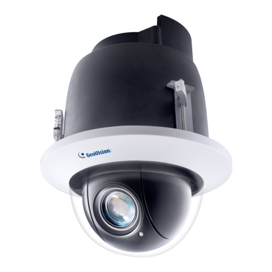
Summary of Contents for GeoVision GV-IP Speed Dome
- Page 1 Quick Start Guide GV-IP Speed Dome GV-QSD5730 GV-QSD5731-IR Before attempting to connect or operate this product, QSD-QG-A please read these instructions carefully and save this manual for future use.
- Page 2 GeoVision. Every effort has been made to ensure that the information in this manual is accurate. GeoVision, Inc. makes no expressed or implied warranty of any kind and assumes no responsibility for errors or omissions. No liability is assumed for incidental or consequential damages arising from the use of the information or products contained herein.
-
Page 3: Table Of Contents
Contents Note for Connecting to GV-VMS / DVR / NVR ..........ii Note for Recording..................... ii 1. Introduction ......................1 1.1 Packing List ....................1 1.2 Overview of GV-QSD5730 ................. 3 1.3 Overview of GV-QSD5731-IR ..............4 2. Installation ......................5 2.1 Installing GV-QSD5730 ................ -
Page 4: Note For Connecting To Gv-Vms / Dvr / Nvr
Note for Connecting to GV-VMS / DVR / NVR The GV-IP Speed Dome is designed to work with GV-VMS / DVR / NVR, a video management system. Note the following when the camera is connected to GV-VMS / DVR / NVR: Once the camera is connected to the GV-VMS / DVR / NVR, the resolution set on the GV-VMS / DVR / NVR will override the resolution set on the camera’s Web interface. -
Page 5: Introduction
Introduction 1. Introduction Welcome to the GV-IP Speed Dome Quick Start Guide. In the following sections, you will learn the basic installations and configurations. For a detailed user manual, see the GV-IP Speed Dome User’s Manual. 1.1 Packing List GV-QSD5730 ... - Page 6 GV-QSD5731-IR GV-QSD5731-IR 3-Pin Power Terminal Block M4 Screw with Rubber 14-Pin Alarm/Audio I/O Terminal Block Pendant cap Download Guide Warranty Card Note: It is required to purchase GV-Mount104-1 / 105-1 / 210-1 / 208-4 to mount GV-QSD5731-IR to a wall, ceiling or pole.
-
Page 7: Overview Of Gv-Qsd5730
Introduction 1.2 Overview of GV-QSD5730 Name Function Console Connector RJ-45 Port For network and PoE connection Power Connector AC 24V power connection For analog video output Audio/Alarm I/O Audio/Alarm I/O & RS-485 connection & RS-485 Connector* Press the button with a proper tool for at least 20 seconds Default Button to restore the system. -
Page 8: Overview Of Gv-Qsd5731-Ir
1.3 Overview of GV-QSD5731-IR Name Function RJ-45 Port For network and PoE connection Power Connector AC 24V power connection Press the button with a proper tool for at least 20 seconds Default Button to restore the system. Audio/Alarm I/O & Audio/Alarm I/O &... -
Page 9: Installation
Installation 2. Installation In the following sections, you will learn how to install GV-QSD5730 to the ceiling with standard packages and how to install GV-QSD5731-IR with optional GV-Mount accessories. 2.1 Installing GV-QSD5730 Required Items Tool for drilling a hole on the ceiling (user-prepared) ... - Page 10 Thread the Ethernet, power, and/or I/O cables through the ceiling opening. Connect the Ethernet, power, and/or I/O cables to the camera. Align and put the camera to the ceiling opening. Extend the ceiling clamps and clamp the camera to the ceiling by fastening the three screws clockwise.
-
Page 11: Installing Gv-Qsd5731-Ir
Installation 2.2 Installing GV-QSD5731-IR Required Items GV-Mount104-1 / GV-Mount105-1 / GV-Mount210-1 / GV-Mount208-4 (user-purchased) M4 Crosshead Screw Driver (user-prepared) SD card (user-prepared) Remove the cover of the SD card slot on the side of the camera. Insert the SD card and secure the cover. -
Page 12: Connecting The Camera
3. Connecting the Camera 3.1 Power Connection To power up the camera, choose one of the following options below. Connect the AC 24V power adaptor to the power connector of the camera and the power outlet. The pin definition of the power connector is as below: Definition AC 24V L (White;... -
Page 13: Audio / Alarm I/O & Rs-485 Connection
Connecting the Camera 3.2 Audio / Alarm I/O & RS-485 Connection Pin definition for I/O and RS-485 connection is as below: Definition Definition Definition Definition GND (Alarm Audio Out Alarm Out B1 Alarm In 4 I/O & RS-485) Alarm Out B2 Alarm In 3 Audio In (Audio I/O) -
Page 14: Accessing The Camera
4. Accessing the Camera 4.1 System Requirements Once installed, your camera is accessible over the network. Make sure your PC has good network connection, and meet the following requirements: Operating System Windows 7 or later Memory Minimum: 4 GB Recommended: 8 GB Minimum: Intel Core i5-2430M, 2.4 GHz Recommended: Intel Core i7-870, 2.93 GHz ... -
Page 15: Looking Up The Dynamic Ip Address
Accessing the Camera 4.2 Looking Up the Dynamic IP Address By default, when the camera is connected to LAN with a DHCP server, it is automatically assigned with a dynamic IP address. Follow the steps below to look up its IP address and set up a login password. -
Page 16: Configuring The Ip Address
5. Select Use fixed IP address. 6. Type the IP address, subnet mask, and default gateway address. Make sure that the IP address of the camera is unique in the network. 7. Click Save. Note: See details in 2.2.3 Network, GV-IP Speed Dome User’s Manual. -
Page 17: The Web Interface
The Web Interface 5. The Web Interface 5.1 Viewing Live View Video Once you log in the Web interface, you will see the live view as shown below. No. Name Function Adjust the camera’s zoom. Zoom Focus Adjust the camera’s focus. Iris Adjust the brightness of the image. - Page 18 10 Live View Pause Pause or restart video streaming. 11 Record Turn on or off video recording. 12 Manual Trigger Turn on or off the manual trigger. Note: See details in 2.1.1 Function Items on Home Page, GV-IP Speed Dome User’s Manual.
-
Page 19: Ptz Functions
Set privacy masks for an intended location. PTZ Setting Configure Flip / Speed by zoom / Auto Calibration / Set Pan Zero. RS485 Select the compatible protocol for connecting Joystick / Keyboard. Note: See details in 2.5 PTZ, GV-IP Speed Dome User’s Manual. -
Page 20: Upgrading System Firmware
6. Upgrading System Firmware GeoVision periodically releases the updated firmware on the website. To load the new firmware into the camera, follow the instructions below. 1. Select System from the top menu > Software Upgrade. This page appears. 2. In Step 1, click the Browse button to locate the firmware file saved at your local computer. -
Page 21: Restoring To Factory Default
1. Select System at the top > Factory Default. This page appears. 2. Select Full Restore, Partial Restore, or Reboot. Note: See details in 2.2.14 Factory Default, GV-IP Speed Dome User’s Manual. 7.2 Directly on the Camera 1. Press and hold the Default Button for about 20 seconds. For GV-QSD5730, see 1.2 Overview of GV-QSD5730;...
Need help?
Do you have a question about the GV-IP Speed Dome and is the answer not in the manual?
Questions and answers