
Related Manuals for GeoVision GV-SD010-18X


Summary of Contents for GeoVision GV-SD010-18X
- Page 1 GV-IP Speed Dome User's Manual Before attempting to connect or operate this product, please read these instructions carefully and save this manual for future use.
- Page 2 9F, No. 246, Sec. 1, Neihu Rd., Neihu District, Taipei, Taiwan Tel: +886-2-8797-8377 Fax: +886-2-8797-8335 http://www.geovision.com.tw Trademarks used in this manual: GeoVision, the GeoVision logo and GV series products are trademarks of GeoVision, Inc. Windows and Windows XP are registered trademarks of Microsoft Corporation. November 2009...
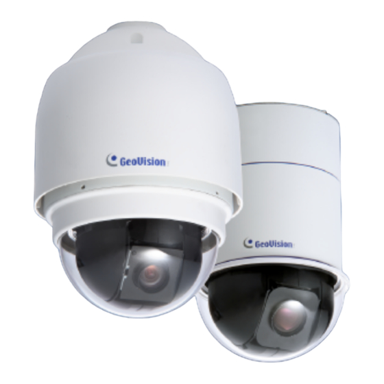
- Page 3 Welcome to the GV-IP Speed Dome User’s Manual. There are two types of the GV-IP Speed Dome, Indoor and Outdoor. Each type also has a series of models designed to meet different needs: Application Model Indoor GV-SD010-18X GV-SD010-23X GV-SD010-36X Outdoor GV-SD010-S18X GV-SD010-S23X GV-SD010-S36X This Manual provides an overview of the GV-IP Speed Dome and its accessories.
-
Page 4: Table Of Contents
Contents Regulatory Notices ....................v Chapter 1 Introduction................... 1 1.1 Overview........................1 1.2 Packing List ......................2 1.2.1 GV-IP Speed Dome of Indoor Type ..............2 1.2.2 GV-IP Speed Dome of Outdoor Type............3 1.3 Functional Panel....................... 4 1.3.1 GV-IP Speed Dome of Indoor Type ..............4 1.3.2 GV-IP Speed Dome of Outdoor Type............5 1.4 Preparing for Outdoor-Type Dome Setup .............. - Page 5 3.2.5 Picture-in-Picture and Picture-and-Picture View.........43 3.2.6 Alarm Notification..................46 3.2.7 Video and Audio Configuration ..............47 3.2.8 Remote Configuration.................47 3.2.9 Camera Name Display................48 3.2.10 Image Enhancement.................48 3.2.11 PTZ Control....................49 3.2.12 Visual PTZ ....................50 3.2.13 I/O Control ....................51 3.2.14 Network Status..................51 Chapter 4 PTZ Control Panel ................52 4.1 Preset Settings .......................
- Page 6 5.6 Network ........................86 5.6.1 LAN......................86 5.6.2 Advanced TCP/IP ..................88 5.6.3 IP Filter .......................90 5.7 Management......................91 5.7.1 Date and Time Settings ................91 5.7.2 GPS Maps Settings ..................93 5.7.3 User Account ....................95 5.8.6 Log Information...................96 5.8.7 Tools ......................97 Chapter 6 Advanced Applications ..............98 6.1 Upgrading System Firmware ..................
- Page 7 9.4 3G Mobile Phone....................124 9.4.1 Activating the 3G Mobile Phone Function..........124 9.4.2 Connecting to the GV-IP Speed Dome .............124 Chapter 10 Optional Power Box................. 126 10.1 Power Box Overview ..................126 10.2 Installation ......................128 10.3 Optional Power Box Specifications..............129 GV-IP Speed Dome Specifications ..............
-
Page 8: Regulatory Notices
Regulatory Notices FCC Notice This equipment has been tested and found to comply with the limits for a Class A digital device, pursuant to part 15 of the FCC Rules. These limits are designed to provide reasonable protection against harmful interference when the equipment is operated in a commercial environment. -
Page 9: Chapter 1 Introduction
Introduction Chapter 1 Introduction 1.1 Overview To meet different needs, the GV-IP Speed Dome is offered in two types: indoor and outdoor. Through both web-based configurations, it is easy to configure and manage the GV-IP Speed Dome. The GV-IP Speed Dome provides variable pan/tilt speeds ranging from a fast patrol of 400° per second to a slow ramble of 5°... -
Page 10: Packing List
1.2 Packing List 1.2.1 GV-IP Speed Dome of Indoor Type Dome Body Hard Ceiling Mount and Decoration Ring Optical Cover Data Cable for Power Supply, Video, Audio and Alarm (Length: 1.3 m / 4.27 ft ) Power Adaptor GV-IP Speed Dome User’s Manual GV-IP Speed Dome Software DVD... -
Page 11: Gv-Ip Speed Dome Of Outdoor Type
Introduction 1.2.2 GV-IP Speed Dome of Outdoor Type Dome Body with Outdoor Mount Kit (which is attached to the Dome) Optical Cover Data Cable for Power Supply, Video, Audio and Alarm (Length: 5 m / 16.4 ft ) Lubricant M3 Standard Screw (x 1), M3 Security Screw (x1), M5 Standard Screw (x1), M5 Security Screw (x1) Security Torx Waterproof Rubber... -
Page 12: Functional Panel
1.3 Functional Panel 1.3.1 GV-IP Speed Dome of Indoor Type Figure 1-1 No. Name Function Resets the GV-IP Speed Dome and keeps all Reset current configurations. Restores all the settings, except PTZ settings, to Default the factory default values. For details see 7.3 Restoring to Factory Default Settings. -
Page 13: Gv-Ip Speed Dome Of Outdoor Type
Introduction 1.3.2 GV-IP Speed Dome of Outdoor Type Figure 1-2 No. Name Function Reset Resets all configurations of GV-IP Speed Dome. Restores all the settings, except PTZ settings, to Default the factory default values. For details see 7.3 Restoring to Factory Default Settings. 22-Pin Connector For details, see 1.6 22-Pin Data Cable. -
Page 14: Preparing For Outdoor-Type Dome Setup
1.4 Preparing for Outdoor-Type Dome Setup The GV-IP Speed Dome of outdoor type is equipped with the sunshield housing. Follow the steps below to complete the housing installation. 1. Unpack the package and take out the GV-IP Speed Dome. Figure 1-3 2. - Page 15 Introduction 3. Remove the protective cover and PE sheet. Figure 1-6 4. Lightly rub a thin layer of lubricant onto the waterproof rubber of the Dome cover before attaching the cover to the body. Figure 1-7 Note that the tiny protrusion on the cover must align with one of the four holes on the Dome body.
- Page 16 5. Gently press down the Dome cover with two hands on the side of it. Figure 1-9 DO NOT press the cover as shown in the figure. This might damage the Dome. Figure 1-10 6. Screw the Dome cover and body together. Figure 1-11...
-
Page 17: Communication Switch
Introduction Communication Switch You can find the Communication Switch below in both indoor and outdoor types of GV-IP Speed Domes. Figure 1-12 SW 1 SW 2 Not Functional SW 3 SW 4 SW 5 Default SW 6 Not Functional SW5 is used to restore all the PTZ settings to original default values. Follow the steps below to restore default PTZ values: 1. -
Page 18: 22-Pin Data Cable
1.6 22-Pin Data Cable With the 22-pin Data Cable, you can connect the power, microphone, speaker, TV monitor and I/O devices to the GV-IP Speed Dome. The Data Cable is illustrated as below. I/O Wires Audio Input 22-Pin Data Cable Speaker Output TV Output Power Input... - Page 19 Introduction Wire Definition for Power Input Connect the three wires of Power Adaptor to the 3-pin terminal block of power input, based on the following wire assignments. Figure 1-14 Wire Assignments for 220 V Power Adaptor Wires of 3-Pin Terminal Block Wires of Power Adaptor Blue Yellow...
-
Page 20: Optional Accessories
1.7 Optional Accessories Optional accessories can be ordered separately depending on the application requirements. Contact your dealer for more information. Model Number Name Details 81-D7H03-ST1 Straight Tube Height: 250 mm / 9.8 in (25 cm) Diameter: 50 mm / 2 in Weight: 1 kg / 2.2 lb Supplied with rubber washer-8 x 1, pendent tube washer x 1, spring washer -8 x 1,... - Page 21 Introduction 81-D7H05-CTB Corner Thin Box Dimensions (L x W x D): Mount 300 x 164 x 222 mm / 11.8 x 6.5 x 8.7 in Weight: 6.7 lb Supplied with washer x 4, M8-16 screw x 4, spring washer x 4 Power Box can be set inside the thin box.
- Page 22 81-D7H06-HCM Hard Ceiling Mount Indoor use only (see Note later) Height: 21.4 mm / 0.84 in Diameter of the three holes: 4.5 mm / 0.17 in Diameter of the bracket: 158 mm / 6.22 in Supplied with Fixing Plate and Red Sticker 81-D7H06-TBC T-Bar Ceiling Mount Indoor use only...
-
Page 23: Chapter 2 Installing The Gv-Ip Speed Dome
Installing the GV-IP Speed Dome Chapter 2 Installing the GV-IP Speed Dome With the proper accessories, GV-IP Speed Dome can adapt to environment requirements to be installed differently. The table below lists a variety of installation methods and the optional accessories you need to purchase for different installation methods. -
Page 24: Ceiling Mount
2.1 Ceiling Mount There are three ceiling mounting methods: Surface Mount, Flush Mount and Straight Tube Mount. The Surface Mount and Flush Mount are only for the GV-IP Speed Dome of Indoor Type. 2.1.1 Surface Mount (Indoor Use Only) Surface Mount is a standard installation method for the GV-IP Speed Dome of Indoor Type. Figure 2-1 Necessary Items include: •... - Page 25 Installing the GV-IP Speed Dome Follow the steps: 1. Screw the Fixing Plate to the GV-IP Speed Dome. Figure 2-2 2. Remove the Decoration Ring from the Hard Ceiling Mount. Figure 2-3 3. Attach the Hard Ceiling Mount to the ceiling. Mark the locations where all three ceiling holes should be drilled.
- Page 26 6. Run the Data and Ethernet cables through the center hole of the Hard Ceiling Mount and connect the cables to the GV-IP Speed Dome. Figure 2-5 7. Attach the Dome body to the Hard Ceiling Mount and rotate the Dome body clockwise. Tighten the screw to fix the Dome body as shown in the picture below.
-
Page 27: Flush Mount (Indoor Use Only)
Installing the GV-IP Speed Dome 2.1.2 Flush Mount (Indoor Use Only) With the optional T-Bar Ceiling Mount, the GV-IP Speed Dome of Indoor Type can be mounted into the ceiling, revealing a small part of the Dome body. Figure 2-8 Necessary items include: •... - Page 28 2. Attach the separated wing to the Dome body as shown in the picture below. Figure 2-10 3. Place the Red Sticker on the ceiling plate, and cut the circle part out of the ceiling. Figure 2-11 4. Put up the T-Bar Ceiling Mount into the ceiling opening. Figure 2-12 5.
- Page 29 Installing the GV-IP Speed Dome 7. Run the Data and Ethernet cables down through the center hole of the T-Bar and connect cables to the GV-IP Speed Dome. Figure 2-14 8. Mount the Dome body to the bracket and rotate it clockwise. Figure 2-15 9.
-
Page 30: Straight Tube Mount (Indoor Type)
2.1.3 Straight Tube Mount (Indoor Type) With the optional Straight Tube, the GV-IP Speed Dome of Indoor Type can be suspended from the ceiling. The Straight Tube is available in two different lengths: 250 mm and 500 mm. Figure 2-17 Necessary items include: •... - Page 31 Installing the GV-IP Speed Dome 4. Run the Data and Ethernet cables through the Straight Tube and the Indoor Mount Kit. Remember to block the cable entry hole with the supplied sponge to prevent insects from entering the tube. 5. Fix the Indoor Mount Kit to the Straight Tube with the supplied screws and washers. 6.
-
Page 32: Straight Tube Mount (Outdoor Type)
2.1.4 Straight Tube Mount (Outdoor Type) With the optional Straight Tube, the GV-IP Speed Dome of Outdoor Type can be suspended from the ceiling. The Straight Tube is available in two different lengths: 250 mm and 500 mm. Figure 2-21 Necessary items include: •... -
Page 33: Wall Mount
Installing the GV-IP Speed Dome 6. Run the cables through the Outdoor Mount Kit and join the Outdoor Mount Kit to the Straight Tube with the supplied screws and washers. Then adjust the Waterproof Rubber to the joint. 7. Connect the cables to the GV-IP Speed Dome. 8. - Page 34 Necessary items for the Dome of Indoor Type: • GV-IP Speed Dome (Indoor Type) • Data Cable (supplied) • Ethernet Cable • Indoor Mount Kit (optional) • Standard Pendent Mount (optional) • Waterproof Rubber (supplied with Indoor Mount Kit) • Screws and screw anchors for fixing the Standard Pendent Mount on the wall (not supplied) Necessary items for the Dome of Outdoor Type:...
- Page 35 Installing the GV-IP Speed Dome Follow the steps: 1. Make a cable entry hole on the wall to recess the Data and Ethernet cables. Otherwise, push up the cable entry board on the mounting plate of Standard Pendant Mount to place the cables as shown in the picture below.
-
Page 36: Mini Pendent Mount
2.2.2 Mini Pendent Mount The installation steps of the Mini Pendent Mount are the same as those of the Standard Pendent Mount. For details, see 2.2.1 Standard Pendent Mount. Figure 2-25 Necessary items for the Dome of Indoor Type: • GV-IP Speed Dome (Indoor Type) •... -
Page 37: Wall Box Mount
Installing the GV-IP Speed Dome 2.2.3 Wall Box Mount With the optional Wall Box Mount and Standard/Mini Pendent Mount, the GV-IP Speed Dome can be installed on the wall. Figure 2-26 Necessary items for the Dome of Indoor Type: • GV-IP Speed Dome (Indoor Type) •... - Page 38 Follow the steps: 1. Make a cable entry hole on the wall to recess the cables. 2. Fix the Wall Box Mount on the wall with proper screws and screw anchors. Then run the Data and Ethernet cables through the hole on the Wall Box Mount. 3.
-
Page 39: Corner Mount
Installing the GV-IP Speed Dome 2.3 Corner Mount There are two corner mounting methods: Corner Plate Mount and Corner Thin Box Mount. The two mounting methods are suitable for both indoor and outdoor installation. 2.3.1 Corner Plate Mount With the optional Corner Plate Mount and Standard/Mini Pendant Mount, the GV-IP Speed Dome can be mounted on the corner wall. - Page 40 Necessary items for the Dome of Outdoor Type: • GV-IP Speed Dome (Outdoor Type) • Data Cable (supplied) • Ethernet Cable • Standard/Mini Pendent Mount (optional) • Corner Plate Mount (optional) • Waterproof Rubber (supplied) • M5 Standard/Security Screw (supplied) •...
-
Page 41: Corner Thin Box Mount
Installing the GV-IP Speed Dome 2.3.2 Corner Thin Box Mount With the optional Corner Thin Box and Standard/Min Pendent Mount, the GV-IP Speed Dome can be mounted on the corner wall. Figure 2-28 Necessary items for the Dome of Indoor Type: •... - Page 42 Follow the steps: 1. Make a cable entry hole on the wall to recess the cables. 2. Fix the Corner Thin Box on the corner of the wall with proper screws and screw anchors. Then run the Data and Ethernet cables through the hole on the Corner Thin Box. 3.
-
Page 43: Pole Mount
Installing the GV-IP Speed Dome 2.4 Pole Mount There are two pole mounting methods: Pole Thin Direct Mount and Pole Thin Box Mount. The two mounting methods are suitable for both indoor and outdoor installation. 2.4.1 Pole Thin Direct Mount With the optional Pole Thin Direct Mount and Standard/Mini Pendent Mount, the GV-IP Speed Dome can be installed on a pole. - Page 44 Necessary items for the Dome of Outdoor Type: • GV-IP Speed Dome (Outdoor Type) • Outdoor Mount Kit (supplied) • Data Cable (supplied) • Ethernet Cable • Standard/Mini Pendent Mount (optional) • Pole Thin Direct Mount (optional) • Waterproof Rubber (supplied) •...
-
Page 45: Pole Thin Box Mount
Installing the GV-IP Speed Dome 2.4.2 Pole Thin Box Mount With the optional Pole Thin Box Mount and Standard/Mini Pendent Mount, the GV-IP Speed Dome can be installed on a pole. Figure 2-30 Necessary items for the Dome of Indoor Type: •... - Page 46 Necessary items for the Dome of Outdoor Type: • GV-IP Speed Dome (Indoor Type) • Data Cable (supplied) • Ethernet Cable • Standard/Mini Pendent Mount (optional) • Pole Thin Box Mount (optional) • Indoor Mount Kit (supplied) • Waterproof Rubber (supplied with Indoor Mount Kit) •...
-
Page 47: Chapter 3 Accessing The Gv-Ip Speed Dome
4. A video image, similar to the example in Figure 3-2, is now displayed in your browser. Note: To enable the updating of images in Microsoft Internet Explorer, you must set your browser to allow ActiveX Controls and perform a once-only installation of GeoVision’s ActiveX component onto your computer. -
Page 48: Functions Featured On The Main Page
3.2 Functions Featured on the Main Page This section introduces the features of the Live View window and Network Status on the main page. The two features are accessible by both Administrator and Guest. Main Page of Guest Mode ▼ Video and Motion ▼... - Page 49 Accessing the GV-IP Speed Dome No. Name Function Play Plays live video. Stop Stops playing video. Microphone Talks to the surveillance area from the local computer. Speaker Listens to the audio around the camera. Takes a snapshot of live video. Snapshot --- See 3.2.3 Snapshot of a Live Video.
-
Page 50: The Control Panel Of The Live View Window
3.2.2 The Control Panel of the Live View Window To open the control panel of the Live View window, click the arrow button on top of the viewer. You can access the following functions by using the right and left arrow buttons on the control panel. -
Page 51: Snapshot Of A Live Video
Accessing the GV-IP Speed Dome 3.2.3 Snapshot of a Live Video To take a snapshot of live video, follow these steps: 1. Click the Snapshot button (No. 5, Figure 3-3). The Save As dialog box appears. 2. Specify Save in, type the File name, and select JPEG or BMP as Save as Type. You may also choose whether to display the name and date stamps on the image. - Page 52 Picture-in-Picture View With the Picture-in-Picture (PIP) view, you can crop the video to get a close-up view or zoom in on the video. Navigation box Inset window Figure 3-5 1. Select PIP. An inset window appears. 2. Click the insert window. A navigation box appears. 3.
- Page 53 Accessing the GV-IP Speed Dome Picture-and-Picture View With the Picture-and-Picture (PAP) view, you can create a split video effect with multiple close-up views on the image. A total of 7 close-up views can be defined. Figure 3-6 1. Select PAP. A row of three inset windows appears at the bottom. 2.
-
Page 54: Alarm Notification
3.2.6 Alarm Notification After input triggers and motion detection, you can be alerted by a pop-up live video and view up to four captured images. Pop-up live video Captured images Figure 3-7 To configure this function, click the Show System Menu button (No. 11, Figure 3-3), and select Alarm Notify. -
Page 55: Video And Audio Configuration
Accessing the GV-IP Speed Dome 3.2.7 Video and Audio Configuration You can enable the microphone and speaker for two-way audio communication and adjust the audio volume. To change audio configuration, click the Show System Menu button (No. 11, Figure 3-3), and select Video and Audio Configuration. Figure 3-9 3.2.8 Remote Configuration You can view the connection status of the central monitoring stations and upgrade firmware... -
Page 56: Camera Name Display
3.2.9 Camera Name Display To display the camera name on the image, click the Show System Menu button (No. 11, Figure 3-3), and select Show Camera Name. 3.2.10 Image Enhancement To enhance the image quality of live video, click the Show System Menu button (No. 11, Figure 3-3), and select Image Enhance. -
Page 57: Ptz Control
Accessing the GV-IP Speed Dome 3.2.11 PTZ Control To open the PTZ Control Panel, click the PTZ Control button (No. 9, Figure 3-3) and select PTZ Control Panel. With the control panel, the Guest can carry out Pan, Tile, Zoom, Focus and Iris functions as well as pre-defined movements. -
Page 58: Visual Ptz
3.2.12 Visual PTZ In additional to the PTZ Control Panel, you can display a visual PTZ Control Panel on the image. Figure 3-12 • To access this feature, click the PTZ Control button (No. 9, Figure 3-3) and select Visual PTZ. -
Page 59: I/O Control
Accessing the GV-IP Speed Dome 3.2.13 I/O Control The I/O Control window provides real-time graphic displays of camera and I/O status, and alarm events. Additionally, you can force output to be triggered. Figure 3-13 • To display the I/O control window, click the I/O Control button (No. 8, Figure 3-3). •... -
Page 60: Chapter 4 Ptz Control Panel
Chapter 4 PTZ Control Panel The PTZ Control Panel allows users to operate the focus, zoom and iris functions. Furthermore, the Administrator can use the PTZ Control Panel to adjust the image settings and plan dome movements, such as preset, cruise, auto pan and sequence. Calling Up the PTZ Control Panel: Click the PTZ Control button (No. - Page 61 PTZ OSD Control Panel Accessing the PTZ Settings Dialog Box: 1. Click Option (Figure 4-1) on the PTZ Control Panel and select Setup. The PTZ Settings dialog box appears Figure 4-2 2. The PT Speed determines the speed at which PTZ will turn from left to right and tilt up and down.
-
Page 62: Preset Settings
4.1 Preset Settings Up to 64 presets can be set up. Setting Up a Preset 1. To set up a preset position, use the direction keys on the PTZ Control Panel to move the Dome to a desired position in Live View. 2. -
Page 63: Auto Pan Mode Settings
PTZ OSD Control Panel 4.3 Auto Pan Mode Settings You can set the GV-IP Speed Dome to stay on a panning mode to survey the horizontal view. Up to 4 Auto Pan modes can be created. Setting Up an Auto Pan Mode 1. -
Page 64: Ptz Setting- Sequence Settings
4.4 PTZ Setting- Sequence Settings To automatically move the Dome based on a predefined route, create a Sequence by linking up a number of presets points. Up to 8 Sequences can be created. A minimum of 2 preset points must be selected for a Sequence route to work. Figure 4-3 Setting Up a Sequence Route 1. -
Page 65: Ptz Setting- Advanced
PTZ OSD Control Panel Starting and Stopping a Sequence Route To start the GV-IP Speed Dome on a Sequence route, click Option (Figure 4-1) on the PTZ Control Panel, click Auto and select a Go Sequence number which has been previously set. To stop a Sequence route in action, click on a direction key, home key, zoom button or focus button on the PTZ Control Panel. - Page 66 Sequence: When the Delay Time is up, the Dome will automatically perform the selected Sequence number. To configure a Sequence, see 4.4 PTZ Settings-Sequence Settings. Auto Pan: When the Delay Time is up, the Dome will automatically perform the selected Auto Pan number. To configure an Auto Pan, see 4.3 Auto Pan Mode Settings.
-
Page 67: Image Setting- White Balance
PTZ OSD Control Panel 4.6 Image Setting- White Balance The White Balance control offers 5 ways to measure color ratios. Figure 4-5 Auto: The Dome automatically adjusts the color to be closest to the image you are viewing. Indoor: The preset White Balance value for indoor lighting. Outdoor: The preset White Balance value for outdoor lighting. -
Page 68: Image Setting- Auto Exposure
Manual: Users can adjust Slow Shutter, Shutter, G Gain and Iris values. • This option is only available on the models GV-SD010-18X, GV-SD010-36X, GV-SD010-S18X and GV-SD010-S36X. AGC Priority: The AGC takes main control of exposure, and both Shutter and Iris function automatically with AGC. - Page 69 Shutter Priority: The shutter speed takes main control of exposure, and both IRIS and AGC function automatically with shutter speed. • On the models GV-SD010-18X, GV-SD010-36X, GV-SD010-S18X and GV-SD010-S36X, you can freely adjust Slow Shutter and Shutter settings. • On the models GV-SD010-23X and GV-SD010-S23X, you can freely adjust Shutter and Backlight settings.
-
Page 70: Image Setting- Mask
Backlight: This option prevents the center object from being too dark in surroundings where excessive light is behind the object. • On the models GV-SD010-18X, GV-SD010-36X, GV-SD010-S18X and GV-SD010-S36X, this option is only available when Full Auto is selected for Auto Exposure. - Page 71 PTZ OSD Control Panel Figure 4-7 1. Use the Mask drop-down list to select On. 2. Set the color of the Mask. The available color choices vary from model to model. 3. Select Set Mask. 4. Use the Index drop-down list to number the Mask. 5.
-
Page 72: Image Setting- Other
Setting-Auto Exposure. Aperture: Adjust the enhancement of object edges. • On the models GV-SD010-18X, GV-SD010-36X, GV-SD010-S18X and GV-SD010-S36X, you can manually adjust the level from 0 to 15. • On the models GV-SD010-23X and GV-SD010-S23X, you can select either Auto mode or Manual mode. -
Page 73: System Configuration
PTZ OSD Control Panel 4.10 System Configuration Figure 4-9 Auto Calibration: There are one horizontal point and one vertical infrared rays check point in the GV-IP Speed Dome. During installation or maintenance, the Dome’s position may be moved. Therefore, the relative distance between the original set point and the check point will be changed. -
Page 74: Chapter 5 Configuration Menu
Chapter 5 Configuration Menu The Administrator can configure the GV-IP Speed Dome over the network. The configuration includes these categories: Video and Motion, Digital I/O and PTZ, Events and Alerts, Monitoring, Recording Schedule, Remote ViewLog, Network and Management. Figure 5-1... -
Page 75: Video & Motion
Configuration Menu 5.1 Video & Motion This section includes the video image settings and motion detection. 5.1.1 Video Settings Figure 5-2... - Page 76 [Name] Rename the camera. The camera name will appear on the Live View. To display the camera name, see 3.2.9 Camera Name Display. [Connection Template] Select the type of your network connection. Unless you select Customized, this option will automatically bring up the recommended video resolution, frame rate, bandwidth and GOP size.
- Page 77 Configuration Menu There are 4 options for selecting image resolutions. NTSC 720 x 576 720 x 480 720 x 480 De-interlaced 720 x 576 De-interlaced 360 x 240 360 x 288 176 x112 176 x 144 Several frame rates are available. Format Frame Rate 1, 2, 3, 5, 7.5, 10, 15, 30...
- Page 78 Pre-alarm recording time: Activates video recording before an event occurs. Set the recording time to 1 or 2 seconds. Post-alarm recording time: Activates video recording onto the connected iSCSI mass storage device after an event occurs. Set the recording time from 1 to 30 seconds. Split Interval: Sets the time length between each event file from 1 to 5 minutes.
-
Page 79: Motion Detection
Configuration Menu 5.1.2 Motion Detection Motion detection is used to generate an alarm whenever movement occurs in the video image. You can configure up to 8 areas with different sensitivity values for motion detection. Figure 5-3 1. The default sensitivity value is 2 for the whole area. To define a different sensitivity value, click Reset. -
Page 80: Digital I/O & Ptz
5.2 Digital I/O & PTZ 5.2.1 Input/Output Settings This section introduces how to configure the I/O devices connected to the GV-IP Speed Dome. 5.2.1.1 Input Setting The GV-IP Speed Dome can connect up to 4 input devices. Figure 5-4 Name: Edit the input name. Normal State: Set up the input state to trigger actions by selecting Open Circuit (N/O) or Grounded Circuit (N/C). - Page 81 Configuration Menu Duration to set preset after input off x seconds: Specify the amount of time the GV-IP Speed Dome stays in “Input on” preset point before moving to “Input off” preset point. Note: The input settings only function after you start Input monitoring manually or by schedule.
-
Page 82: Ptz Settings
5.2.2 PTZ Settings A PTZ configuration dialog box is provided for you to configure and control the GV-IP Speed Dome. For details, see Chapter 4 PTZ Control Panel. Figure 5-6 5.3 Events & Alerts For the events of motion detection or I/O trigger, the Administrator can set up the two trigger actions: 1. -
Page 83: E-Mail
Configuration Menu 5.3.1 E-mail After a trigger event, the GV-IP Speed Dome can send the e-mail to a remote user containing a captured still image. Figure 5-7 [Enable] Select to enable the e-mail function. Sever URL/IP Address: Type the SMTP Server’s URL address or IP address. Server Port: Type the SMTP Server’s port number. -
Page 84: Ftp
5.3.2 FTP You can also send the captured still image to a remote FTP server for alerts. Figure 5-8 [Upload to a FTP Server] Enable: Select to enable the FTP function. Server URL/IP Address: Type the URL address or IP address of the FTP Server. Server Port: Type the port number of the FTP Server. - Page 85 Configuration Menu [Alarm Settings] Motion Detection: Once the motion is detected in the camera view, a still image will be sent to the FTP Server. Continuously send images upon trigger events (motion): A sequence of snapshot images are uploaded to the FTP Server when motion is detected in the camera view. Digital Input: Once the input is triggered, a still image will be sent to the FTP Server.
-
Page 86: Center V2
5.3.3 Center V2 After a motion or an I/O triggered event, the central monitoring station Center V2 can get notified by live videos and text alerts. For the live monitoring through Center V2, you must already have a subscriber account on Center V2. Figure 5-9 To enable the Center V2 connection: 1. - Page 87 Configuration Menu These options you can also find on this Center V2 setting page: Cease motion detection messages from: Stops notifying Center V2 of motion detection. Cease input trigger messages from: Stops notifying Center V2 of input trigger from selected input(s). Enable schedule mode: Starts the monitoring through Center V2 based on the schedule you set in the Select Schedule Time section.
-
Page 88: Vsm
5.3.4 VSM After a motion or an I/O triggered event, the central monitoring station VSM can get notified by text alerts. For the live monitoring through VSM, you must already have a subscriber account on VSM. Figure 5-10 To enable the VSM connection: 1. - Page 89 Configuration Menu These options you can also find on this VSM setting page: Cease motion detection messages from: Stops notifying VSM of motion detection. Cease input trigger messages from: Stops notifying VSM of input trigger from selected input(s). Enable schedule mode: Starts the monitoring through VSM based on the schedule you set in the Select Schedule Time section.
-
Page 90: 3Gpp
5.3.5 3GPP The 3GPP Server enables video and audio streaming to your 3G-enabled mobile phone. Figure 5-11 Activate Link: Enable the 3GPP service. RTSP/TCP Port: Keep the default value 8554, or modify it if necessary. RTP/UDP Port: Keep the default range from 17300 to 17319, or modify it if necessary. The number of ports for use is limited to 20. -
Page 91: Monitoring
Configuration Menu 5.4 Monitoring You can start recording manually, by schedule or by input trigger. Figure 5-12 [Manual] Manually activates motion detection and I/O monitoring. Select one of the following options and then click the Start button. Select all: Manually starts motion detection and I/O monitoring as well. Camera: Manually starts motion detection. -
Page 92: Recording Schedule
5.5 Recording Schedule The schedule is provided to activate recording and I/O monitoring on a specific time each day. 5.5.1 Recording Schedule Settings You can set up different monitoring schedules for each camera. Figure 5-13 Span 1- Span 3: Set different time frame during the day to start motion detection. Each day can be divided into 3 time frames, represented by Span 1 to Span 3. -
Page 93: I/O Monitoring Settings
Configuration Menu 5.5.2 I/O Monitoring Settings You can set the schedule for I/O monitoring to start. Figure 5-14 Span 1-3: Set different time frames during the day to start I/O monitoring. Each day can be divided into 3 time frames, represented by Span 1 to Span 3. The time frame you specify is effective from Monday through Sunday. -
Page 94: Network
5.6 Network The Network section includes some basic but important network configurations that enable the GV-IP Speed Dome to be connected to a TCP/IP network. 5.6.1 LAN According to your network environment, select among Static IP, DHCP and PPPoE. Figure 5-15 [LAN Configuration] The GV-IP Speed Dome supports the Wired ethernet connection of 10/100 Mbps. - Page 95 Configuration Menu [LAN Configuration] Dynamic IP address: The network environment has a DHCP server. This option should only be enabled if you know which IP address the GV-IP Speed Dome will get from the DHCP server, or you have obtained a domain name from the DDNS service provider that always links to the unit’s changing IP address.
-
Page 96: Advanced Tcp/Ip
5.6.2 Advanced TCP/IP This section introduces the advanced TCP/IP settings, including DDNS Server, HTTP port, streaming port and UPnP. Figure 5-16 [Dynamic DNS Server Settings] DDNS (Dynamic Domain Name System) provides a convenient way of accessing the GV-IP Speed Dome when using a dynamic IP. DDNS assigns a domain name to the GV-IP Speed Dome, so that the Administrator does not need to go through the trouble of checking if the IP address assigned by DHCP Server or ISP (in xDSL connection) has changed. - Page 97 2. Service Provider: Select the DDNS service provider you have registered with. 3. Host Name: Type the host name used to link to the GV-IP Speed Dome. For the users of GeoVision DDNS Server, it is unnecessary to fill the field because the system will detect the host name automatically.
-
Page 98: Ip Filter
5.6.3 IP Filter The Administrator can set IP filtering to restrict access to the GV-IP Speed Dome. Figure 5-17 To enable the IP Filter function: 1. Enable IP Filtering: Enable the IP Filtering function. 2. Filtered IP: Type the IP address you want to restrict the access. 3. -
Page 99: Management
Configuration Menu 5.7 Management The Management section includes the settings of data and time, GPS Maps and user account. Also you can view the firmware version and execute certain system operations. 5.7.1 Date and Time Settings The date and time settings are used for date and time stamps on the image. Figure 5-18... - Page 100 [Date & Time on IP SpeedDome] Displays the current date and time on the GV-IP Speed Dome. [Time Zone] Sets the time zone for local settings. Select Enable Daylight Saving Time to automatically adjust the GV-IP Speed Dome for daylight saving time. Type the Start Time and End Time to enable the daylight saving function.
-
Page 101: Gps Maps Settings
Configuration Menu 5.7.2 GPS Maps Settings The Maps Settings allows you to see the location of your GV-IP Speed Dome on Google maps, without the need of a GPS device. To see the location of your GV-IP Speed Dome on maps: 1. - Page 102 4. Click Open. A warning message appears. Figure 5-21 5. Right-click the warning message and select Allow Blocked Content. The map will be displayed. The icon indicates the location of your GV-IP Speed Dome. In the upper right corner you have options to view different map formats, such as Satellite and Hybrid. Figure 5-22...
-
Page 103: User Account
Configuration Menu 5.7.3 User Account You can change the login name and password of Administrator, Guest and FTP Server User. • The default Administrator login name and password are admin. • The default Guest login name and password are guest. To allow a Guest user log in without entering name and password, select Disable authentication for guest account. -
Page 104: Log Information
5.8.6 Log Information The log contains dump data that is used by service personnel for analyzing problems. Figure 5-24... -
Page 105: Tools
Configuration Menu 5.8.7 Tools This section allows you to execute certain system operations and view the firmware version. Figure 5-25 [Host Settings] Enter a descriptive name for the GV-IP Speed Dome. [Firmware Update] This field displays the firmware version of the GV-IP Speed Dome. [Camera Model Information] This field displays the model name of the GV-IP Speed Dome. -
Page 106: Chapter 6 Advanced Applications
This chapter introduces more advanced applications. 6.1 Upgrading System Firmware GeoVision will periodically release the updated firmware on the website. The new firmware can be simply loaded into the GV-IP Speed Dome by using the Web interface or the IP Device Utility included on the Software DVD. -
Page 107: Using The Ip Device Utility
Advanced Applications Figure 6-1 2. Click the Browser button to locate the firmware file (.img) saved at your local computer. 3. Click the Firmware Upgrade button to process the upgrade. 6.1.2 Using the IP Device Utility The IP Device Utility provides a direct way to upgrade the firmware to multiple GV-IP Speed Domes. - Page 108 3. Click the Search button to locate the available GV-IP Speed Domes on the same LAN. Or click the New button and assign the IP address to locate a GV-IP Speed Dome on the Internet. Or highlight one GV-IP Speed Dome in the list and click the Delete button to remove it.
-
Page 109: Backing Up And Restoring Settings
Advanced Applications 5. Click the Firmware Upgrade tab. This dialog box appears. Figure 6-4 6. Click the Browse button to locate the firmware file (.img) saved at your local computer. 7. If you like to upgrade all the GV-IP Speed Domes in the list, check Upgrade all devices. 8. - Page 110 Figure 6-5 4. Click the Browse button to assign a file path. 5. Type Password, and click Export Settings to save the backup file. To restore the settings: 1. In Figure 6-3, click the Import Settings tab. This dialog box appears. Figure 6-6 2.
-
Page 111: Restoring To Factory Default Settings
Advanced Applications 6.3 Restoring to Factory Default Settings The settings of GV-IP Speed Dome are divided into two categories: PTZ settings and other settings. Therefore the operations of restoring the two setting categories to original default values are separate and different. To restore all settings, except PTZ settings, to default values: Use the Reset and Default buttons on the GV-IP Speed Dome to perform this action. -
Page 112: Chapter 7 Dvr Configurations
Chapter 7 DVR Configurations The GV-System provides hybrid solution, integrating the digital videos from GV-IP Speed Dome with other analog videos. For the digital videos, the GV-System provides the complete video management, such as video viewing, recording, playback, alert settings and almost every feature of the system. -
Page 113: Setting Up Ip Cameras
DVR Configurations 7.1 Setting Up IP Cameras To set up IP cameras on the GV-System, follow these steps: 1. On the main screen, click the Configure button, select General Setting, select Camera / Audio Install and click IP Camera Install. This dialog box appears. Figure 7-2 2. - Page 114 4. Type the IP address, username and password of the GV-IP Speed Dome. Modify the default HTTP port if necessary. Select GeoVision from the Brand drop-down list and select GeoVison IP Speed Dome from the Device drop-down list. This dialog box appears.
- Page 115 DVR Configurations Previewing Video and Setting Audio To preview video and activate audio recoding, highlight the desired GV-IP Speed Dome and select Preview & Audio Setting (Figure 7-6). This dialog box appears. Figure 7-7 [Preview selected camera] Drop-down List: Select the desired camera for live preview. Preview dual stream record channel: The option is only available when the dual stream is set, i.e.
- Page 116 Center V2, Control Center and WebCam. This function is useful when many remote servers access GV-System at one time. When the option is selected, it can reduce the system load on GV-System, and provide more frame rates and better image quality for each remote server. Note: It is highly recommended to enable this function on a LAN environment because it requires a lot of bandwidth.
-
Page 117: Remote Monitoring With Multi View
DVR Configurations 7.2 Remote Monitoring with Multi View You can use the Multi View to monitor the video and I/O devices connected from the GV-IP Speed Dome. Connecting to GV-IP Speed Dome The Multi View program is available in the GV-System applications, and also included on the Software DVD as an independent program. - Page 118 Figure 7-8 7. Click Save to establish connection. For details on the Multi View functions, see “Multi View MPEG 4 Encoder Viewer”, Chapter 8, User’s Manual on the Surveillance System Software DVD.
-
Page 119: Remote Monitoring With E-Map
DVR Configurations 7.3 Remote Monitoring with E-Map You can use the Remote E-Map to monitor the video and I/O devices connected from the GV-IP Speed Dome. Creating an E-Map for the GV-IP Speed Dome With the E-Map Editor, you can create an E-Map for the GV-IP Speed Dome and I/O devices connected to the Dome. - Page 120 Connecting to GV-IP Speed Dome Depending on where you save the created E-Map file (GV-System, E-Map Server or Control Center), the steps to open the Remote E-Map window for monitoring may vary slightly. The following is the connection example when you store the E-Map file in the GV-System. 1.
-
Page 121: Chapter 8 Cms Configurations
CMS Configurations Chapter 8 CMS Configurations This section introduces the related settings to enable connecting to the GV-IP Speed Dome in the central monitoring stations Center V2, VSM and Dispatch Server. 8.1 Center V2 The Center V2 can monitor the video and I/O devices connected from the GV-IP Speed Dome. - Page 122 To define how to display the received video on motion detection and input trigger from the GV-IP Speed Dome, click the Preference Setting button and select System Configure. This dialog box appears. Figure 8-3 Manual close channel: Closes the triggered camera view manually. Close the camera view when motion stopped: Closes the triggered camera view automatically when motion stops.
-
Page 123: Vsm
CMS Configurations 8.2 VSM The VSM can monitor the video and I/O devices connected from the GV-IP Speed Dome. TCP/ IP GV-IP Speed Dome Text Data GV-IP Speed Dome Figure 8-4 To set the appropriate port connecting to the GV-IP Speed Dome, click Configure on the window menu, and select System Configure to display this dialog box. -
Page 124: Dispatch Server
8.3 Dispatch Server The Dispatch Server can manage the video and I/O devices connected from the GV-IP Speed Dome, and distribute them to the Center V2. TCP/ IP GV-IP Speed Dome Center V2 Video Data Text Data Dispatch Server GV-IP Speed Dome Center V2 Figure 8-6 To enable connecting to the GV-IP Speed Dome, click the Server Setting button on... -
Page 125: Chapter 9 Mobile Phone Connection
Mobile Phone Connection Chapter 9 Mobile Phone Connection Using a PDA, Smartphone or 3G-enabled mobile phone, you can receive live video streaming from the GV-IP Speed Dome. The chart below lists the GV mobile applications supporting the GV-IP Speed Dome. Handheld Settings on OS Supported... -
Page 126: Pda
GView V2 should be installed on a PDA device with Microsoft Windows Mobile operating system. 1. Download and install Microsoft PDA Viewer V2 from http://www.geovision.com.tw/english/5_3.asp to the computer. 2. Follow the on-screen instructions to complete the installation. The default installation directory is C:\Microsoft PDA Viewer V2. -
Page 127: Connecting To Gv-Ip Speed Dome
Mobile Phone Connection 9.1.3 Connecting to GV-IP Speed Dome Once GView V2 is installed on your PDA, you can use it to monitor your GV-IP Speed Dome. Make sure your PDA has wireless LAN adapter properly in place with access to the Internet. 1. -
Page 128: Windows Smartphone
9.2.1 Installing MSView V2 / V3 1. Download and install Microsoft Smaprtphone Viewer V2 or Microsoft Smarphone Viewer V3 from http://www.geovision.com.tw/english/5_3.asp to the computer. 2. Follow the on-screen instructions to complete the installation. The default installation directory is C:\SmartPhone Viewer V2 or C:\SmartPhone Viewer V3. - Page 129 Mobile Phone Connection 2. Click Type and then Live. Figure 9-4 3. On the login screen, enter the IP address of your GV-IP Speed Dome, port value (default value is 10000), a username and a password. Then click Control and select Connect. Figure 9-5 4.
-
Page 130: Symbian Smartphone
To install SSView Version 3 for Nokia S60 2nd and 3rd Edition: 1. Download and install Symbian Smartphone Viewer V3 from http://www.geovision.com.tw/english/5_3.asp to the computer. 2. Follow the on-screen instructions to complete the installation. The default installation directory is C:\Symbain SmartPhone Viewer V3. -
Page 131: Activating The Ssview V3 Function
Mobile Phone Connection 9.3.2 Activating the SSView V3 Function To allow remote access to the GV-IP Speed Dome, you must select 3GPP, MSViewV2, SSViewV3 Supported to be the connection type in the Connection Template field on the Video Settings page. For details, see “Connection Template” in 5.1.1 Video Settings. 9.3.3 Connecting to GV-IP Speed Dome The following operations may vary slightly for different modules. -
Page 132: Quick Connection
9.3.4 Quick Connection The IP addresses of connected GV-IP Speed Domes can be stored for quick connection in the future. Press the [<] and [>] buttons on the mobile device to select the desired GV-IP Speed Dome for connection. 9.4 3G Mobile Phone Without installing any GV applications, you can use a 3G mobile phone to access GV-IP Speed Dome directly. - Page 133 Mobile Phone Connection 3. Select the desired channel. Its live image will appear. Figure 9-11...
-
Page 134: Chapter 10 Optional Power Box
Chapter 10 Optional Power Box The optional Power Box contains one AC 24V adapter and two terminal blocks for communication and power supply. With an IP66 case, the Power Box is ideal for outdoor installation environment. For operating in different installation environment, two types of power inputs are available: AC 100~115V and AC 220~230V. - Page 135 Optional Power Box 1 & 2: Commutation Signal Terminal Block 1 (J1) 2 (J6) Definition Definition Audio GND Audio GND Audio Out Audio Out Audio In Audio In Audio GND Audio GND ISOG Not Functional ISOG Not Functional VGND Video GND VGND Video GND VIDEO...
-
Page 136: Installation
10.2 Installation 1. Screw the lid off the unit. 2. Remove the cushion in the Power Box. Figure 10-2 3. Refer to the pin assignment of Power Box mentioned earlier for connecting the commutation and power wires. 4. Adjust the power supply switch to the appropriate voltage. 5. -
Page 137: Optional Power Box Specifications
Optional Power Box 10.3 Optional Power Box Specifications Electrical Power Source AC 100~115V / 220~230V @ 50-60 Hz Input Current 1.0A Output Current AC 24V (max AC 29V), 3.0A max. Mechanical Environment Indoor / Outdoor Wall Mounting Option Bracket plate Dimensions 187 x 147 x 76 mm (7.36 x 5.78 x 3 in) (H x W x D) -
Page 138: Gv-Ip Speed Dome Specifications
GV-IP Speed Dome Specifications Type Indoor Outdoor Model GV-SD010-18X GV-SD010-23X GV-SD010-36X GV-SD010-S18X GV-SD010-S23X GV-SD010-S36X Camera 1/4" 1/4" 1/4" 1/4" 1/4" 1/4" Image Sensor Exview CCD Progressive CCD Exview CCD Exview CCD Progressive CCD ExviewCCD Optical Zoom Digital Zoom NTSC 380k... -
Page 139: Specifications
Specifications Type Indoor Outdoor Model GV-SD010-18X GV-SD010-23X GV-SD010-36X GV-SD010-S18X GV-SD010-S23X GV-SD010-S36X Operation Pan Travel 360° endless Tilt Travel -10° ~ 190° Manual Speed 0.5° ~ 90°/s Preset Preset Accuracy 0.225° Preset Speed 5° ~ 400°/s Sequence Auto Pan Cruise Privacy Mask Proportional Pan &... -
Page 140: Appendix
Appendix Shutter Speed Unit: 1/second GV-SD010-18X GV-SD010-23X Shutter GV-SD010-S18X GV-SD010-S23X Value GV-SD010-36X GV-SD010-S36X NTSC NTSC PAL 10000 10000 6000 6000 4000 3500 3000 2500 2000 1750 1500 1250 1000 1000 30000 30000 10000 10000 4000 4000 2000 2000 1000 1000...
Need help?
Do you have a question about the GV-SD010-18X and is the answer not in the manual?
Questions and answers