
Subscribe to Our Youtube Channel
Related Manuals for GeoVision 86-PPTZ730-P01U


Summary of Contents for GeoVision 86-PPTZ730-P01U
- Page 1 Quick Start Guide GV-Panoramic PTZ Camera Before attempting to connect or operate this product, please read these instructions carefully and save this manual for future use. PPTZV10-QG-A...
- Page 2 GeoVision. Every effort has been made to ensure that the information in this manual is accurate. GeoVision, Inc. makes no expressed or implied warranty of any kind and assumes no responsibility for errors or omissions. No liability is assumed for incidental or consequential damages arising from the use of the information or products contained herein.
-
Page 3: Table Of Contents
Contents Note for Connecting to GV-VMS ............ii Note for Recording................iii Note for Installing Camera..............iv Optional Accessories................v 1. Introduction..................1 1.1 Packing List ......................2 1.2 Overview........................3 2. Installation..................4 3. Connecting the Camera ..............10 4. Accessing the GV-Fisheye Camera ..........12 4.1 Web Browser ......................12 4.2 Looking Up the Dynamic IP Address..............13 4.3 Configuring the IP Address..................15 5. -
Page 4: Note For Connecting To Gv-Vms
Note for Connecting to GV-VMS The GV-Panoramic PTZ IP Camera is designed to work with GV-VMS, a video management system. Note the following when the camera is connected to GV-VMS: 1. By default, the images are recorded to the memory card inserted in the GV- Panoramic PTZ IP Camera. -
Page 5: Note For Recording
Note for Recording 1. By default, the images are recorded to the memory cards inserted in the GV-PPTZ Camera. Make sure the Write recording data into local storage option (see 4.1.1 Video Settings, Chapter 4, GV-Panoramic PTZ Camera User’s Manual) is enabled. If this option is disabled, the camera will stop recording to the memory card while the live view is accessed through Web browsers or other applications. -
Page 6: Note For Installing Camera
Note for Installing Camera When installing GV-Panoramic PTZ IP Camera, be sure that: The camera is set up above the junction box to prevent water from entering the camera along the cables. Any PoE, power, audio and I/O cables are waterproofed using waterproof silicon rubber or the like. -
Page 7: Optional Accessories
Optional Accessories Optional devices can expand the capabilities and versatility of your camera. Contact your dealer for more information. Name Details The GV-PA901 is a Power over Ethernet (PoE) adapter GV-PA901 designed to provide power to the IP device through a single Power over Ethernet (PoE) Ethernet cable to GV-PPTZ7300. -
Page 8: Introduction
Introduction 1. Introduction Welcome to the GV-Panoramic PTZ Camera Quick Start Guide. In the following sections, you will learn the basic installations and configurations of GV-Panoramic PTZ Camera. For a detailed user manual, see the GV-Panoramic PTZ Camera User’s Manual on the Software DVD. -
Page 9: Packing List
1.1 Packing List Panoramic PTZ Camera Data Cable Mounting Bracket Mounting Cap Tube 2 mm Hex Key 3 mm Hex Key 5 mm Hex Key Rubber ring RJ-45 Connector Desiccant Pack x 2 ... -
Page 10: Overview
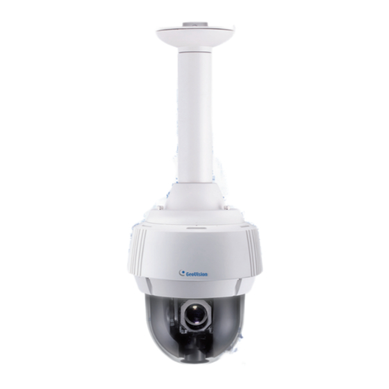
Introduction 1.2 Overview Name Function Flashes when the camera is powering on and loading default Status LED settings. Default Button Resets all configurations to default factory settings. Speed Dome SD Inserts a micro SD card (SD/SDHC, version 2.0, Class 10) to Card Slot store recording data from the speed dome. -
Page 11: Installation
2. Installation GV-Panoramic PTZ Camera can be mounted on the ceiling using the supplied Straight Tube Mount. Make sure the ceiling has enough strength to support the camera and the mount. Required items: • Screws for ceiling x 4 (Self-prepared) Optionally extend with: •... - Page 12 Installation 1. Insert the desiccants to the camera. Remove the camera cover using the 3 mm hex key. Insert your SD cards into the SD card slots for the fisheye camera and the speed dome. Insert one desiccant pack to the indicated place. IMPORTANT: Be sure the desiccant is concealed in the camera within 2 minutes of opening the desiccant pack.
- Page 13 2. Assemble the supplied mounting bracket, tube and mounting cap by rotating the parts together. 3. Make sure the tubes are properly screwed. Tighten the screws using the 2 mm hex key. 4. Connect the cables to the camera. At the back of the camera, remove the cap and use the 3 mm hex key to remove the mounting plate.
- Page 14 Installation Slide the cap and components through the Ethernet cable as shown below, and attach the supplied RJ-45 connector to the cable. Insert the Ethernet cable to the LAN port, move the cap and the components toward the LAN port, and secure the cap tightly. Slip the rubber ring on the data cable and then pass the pin connectors of the data cable through the mounting plate.
- Page 15 Fasten the data cable with the mounting plate and the rubber ring. Insert the pin connectors of the data cable to the indicated area. G. Secure the mounting plate with the 3 mm hex key. 5. Thread the cables through the tube. 6.
- Page 16 Installation Push the rivets into the holes on the mounting cap and rotate clockwise to lock the position. Rotate the camera onto the mounting cap and secure using the 5 mm hex key. 7. Secure the assembled camera to the ceiling with 4 self-prepared screws.
-
Page 17: Connecting The Camera
3. Connecting the Camera The GV-PPTZ7300 comes with a data cable that allows you to connect to the power adapter, microphone, speaker, and any I/O devices. Follow the steps below to connect the camera. Connect Power using one of the following methods: ... - Page 18 Connecting the Camera I/O Wire Definition No. Wire Definition Orange Alarm In 1 Yellow Alarm In 2 Green Alarm In 3 Blue Alarm In 4 Pink Ground Purple Alarm Out White Alarm Out_Open Gray Alarm Out_Close Connecting the GV-PA901 PoE Adapter Connect one end of an Ethernet cable to the LAN 10 / 100 Port on the GV-PA901 and the other end to a Hub / Router.
-
Page 19: Accessing The Gv-Fisheye Camera
4. Accessing GV-Panoramic PTZ Camera 4.1 Web Browser Once installed, your camera is accessible over the network. Make sure your PC has good network connection, and meet the following requirement. Windows 7 / 8 / 8.1 / 10 / Server 2008 R2 / Server 2012 R2 64-bit V15.10.1.0 with patch files or later versions GV-VMS... -
Page 20: Looking Up The Dynamic Ip Address
Accessing GV-Panoramic PTZ Camera 4.2 Looking Up the Dynamic IP Address By default, when GV-Panoramic PTZ camera is connected to LAN with a DHCP server, it is automatically assigned with a dynamic IP address. Follow the steps below to look up its IP address. - Page 21 4. The login page appears. 5. Type the default ID and password admin and click Apply to login.
-
Page 22: Configuring The Ip Address
Speed dome interface: 192.168.0.11 Follow the steps below to assign a new IP address for both the fisheye and speed dome interfaces to avoid IP conflict with other GeoVision devices. Note: The computer used to set the IP address must be under the same network with the camera. - Page 23 4. Type the default value admin again and click Apply 5. Select Static IP address. Type IP Address, Subnet Mask, Router/Gateway, Primary DNS and Secondary DNS in the Configure connection parameters section. 6. Click Apply. The integrated interface and fisheye interface are now accessible by entering the assigned IP address on the Web browser.
-
Page 24: The Integrated Web Interface
The Web Interface 5. The Integrated Web Interface Once you log in the Web interface, you will see the live views of both the fisheye and the speed dome. To access the individual Web interface of the fisheye camera and the speed dome, select GV-PPTZ7300-FE or GV-PPTZ7300-SD under Camera Setting. - Page 25 PIP Mode (Left / Right) Under the PIP Mode, the fisheye live view appears as an inset window inside the speed dome live view. You can select Left to place the fisheye inset window on the lower-left corner or select Right to place it on the lower-right corner. Camera Settings You can link to the individual Web interface of the fisheye camera and the speed dome camera.
-
Page 26: Fisheye View
The Web Interface 5.1 Fisheye View To enable the fisheye options, right-click the fisheye live view and select Geo Fisheye. Once enabled, you can click on the fisheye live view, and the camera will turn toward the selected location. Right-click the image again and select Fisheye Option to see the following options. ... - Page 27 Camera Position: This option is only available under 360 View. You can temporarily set the camera position to Ground instead of the default Ceiling if you want to test the camera view prior to installing the camera on the ceiling.
-
Page 28: Speed Dome View
The Web Interface 5.2 Speed Dome View No. Name Function 1 Play Plays the live video of the fisheye camera and the speed dome. 2 Stop Stops playing video from the fisheye camera and the speed dome. 3 Microphone Talks to the surveillance area from the local computer. 4 Speaker Listens to the audio around the camera. -
Page 29: Upgrading System Firmware
6. Upgrading System Firmware GeoVision periodically releases the updated firmware on the website. To load the new firmware into the GV-Panoramic PTZ Camera, follow the instructions below. Important: For GV-PPTZ7300, you need to go through the firmware update process twice: once for the fisheye camera and once for speed dome. -
Page 30: Restoring To Factory Default
The Web Interface 7. Restoring to Factory Default You can restore the camera to factory default settings using the Web interface or directly on the camera. 7.1 Using the Web Interface 1. In the left menu, select Management and select Tools. 2.
Need help?
Do you have a question about the 86-PPTZ730-P01U and is the answer not in the manual?
Questions and answers