
Related Manuals for GeoVision GV-IP LPR-DL


Summary of Contents for GeoVision GV-IP LPR-DL
- Page 1 GV-IP LPR-DL User's Manual GV-LPR2800-DL GV-LPR2811-DL Before attempting to connect or operate this product, please read these instructions carefully and save this manual for future use. IPLPR-DL-UM-A...
- Page 2 GeoVision. Every effort has been made to ensure that the information in this manual is accurate. GeoVision, Inc. makes no expressed or implied warranty of any kind and assumes no responsibility for errors or omissions. No liability is assumed for incidental or consequential damages arising from the use of the information or products contained herein.
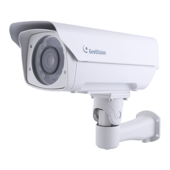
- Page 3 Preface Welcome to the GV-IP LPR Camera User’s Manual. GV-IP LPR Camera is an IP camera designed for instantaneous license plate recognition under various surveillance scenarios. This manual consists of the following models: Models GV-LPR2800-DL GV-LPR2811-DL...
-
Page 4: Table Of Contents
Contents Naming Definition..................... v Options ........................vi Note for Connecting to GV-DVR / NVR / VMS............viii Note for Installing Camera Outdoor ..............viii Note for Silica Gel Bags ..................viii Chapter 1 Introduction................... 1 1.1 System Requirements ....................1 1.2 Key Features ......................2 1.3 GV-LPR2800-DL.......................3 1.3.1 Packing List ....................3 1.3.2 Installing the Camera..................4 1.3.3 Overview &... - Page 5 2.12 Visual Automation ....................32 Chapter 3 Administrator Mode................33 3.1 System ........................35 3.1.1 General Settings..................35 3.1.2 Maintenance....................37 3.1.3 Security ...................... 38 3.1.4 Account Management.................39 3.1.5 V/A License Management................41 3.2 Network ........................42 3.2.1 Basic Settings..................... 42 3.2.2 SNMP......................
- Page 6 3.8.2 VSM (Vital Sign Monitor) ................81 3.8.2 GV-Video Gateway / GV-Recording Server ..........83 Chapter 4 Advanced Applications ..............85 4.1 Upgrading System Firmware .................. 85 4.1.1 Using the Web Interface ................86 4.1.2 Using the GV-IP Device Utility ..............87 4.2 Backing up and Restoring Settings .................
-
Page 7: Naming Definition
Naming Definition GeoVision Analog and Digital Video Recording Software. The GV-DVR / NVR also refers to Multicam System, GV-NVR GV-DVR / NVR system, GV-DVR system and GV-Hybrid DVR system at the same time. GeoVision Video Management System for IP cameras. -
Page 8: Options
Options Optional devices can expand the capabilities and versatility of your camera. Contact your dealer for more information. Device Description GV PA191 is an IEEE802.3af/at PoE adapter, with a maximum power GV-PA191 output of 19 W, that can be used to power GV-IP devices while providing (for LPR2811-DL) Internet connection via an Ethernet cable. -
Page 9: Note For Connecting To Gv-Dvr / Nvr / Vms
Note for Connecting to GV-DVR / NVR / VMS The GV-IP LPR-DL Camera is designed to work with and record on GV-DVR / NVR / VMS, a video management system. Once the camera is connected to a GV-DVR / NVR / VMS, the resolution set on the GV-DVR / NVR / VMS will override the resolution set on the camera’s Web interface. -
Page 10: Note For Installing Camera Outdoor
Note for Installing Camera Outdoor When installing the GV-IP LPR-DL Camera outdoor, mind the following: 1. Set the camera above the junction box to prevent water from entering the camera along the cables. 2. Waterproof the PoE, power and any other cables with waterproof silicon rubber or the like. -
Page 11: Chapter 1 Introduction
Introduction Chapter 1 Introduction 1.1 System Requirements To access the camera functions and settings through Web browser, ensure your PC is in good network connection and use one of the following Web browsers: Microsoft Internet Explorer 11.0 or later Google Chrome ... -
Page 12: Key Features
1.2 Key Features Built-in deep learning LPR processor for license plate recognition 1/2.8” progressive scan super low lux CMOS Min. illumination at 0.04 lux Triple streams from H.265, H.264 and MJPEG Up to 60 fps at 1920 x 1080 ... -
Page 13: Gv-Lpr2800-Dl
Introduction 1.3 GV-LPR2800-DL Ideal for parking lot and roadside installation, GV-LPR2800-DL is a 2 MP color network camera designed for recognition of non-reflective license plates on vehicles traveling at up to 100 km/h (62 mph). With its multiple high-power LEDs and intelligent IR, the camera is able to automatically adjust its shutter speed to the scene and capture clear license plate images for single- and/or dual-lane scenarios under low-light conditions. -
Page 14: Installing The Camera
1.3.2 Installing the Camera IMPORTANT: To produce quality image and to avoid software recognition errors, make sure you adhere to the guidelines as specified in GV-LPR2800-DL Camera Installation Guide. After you have read through the installation guides and chosen an installation site, follow the steps below to install the camera. - Page 15 Introduction 5. Connect the camera for power and network connection. See 1.5 Connecting the Camera. 6. Access the live view. See Chapter 2 Accessing the Camera. 7. Based on the live view, adjust the tilt and pan angle of the camera by loosening the screw as indicated with the supplied hex wrench.
- Page 16 9. Based on the live view, adjust the zoom and focus of the camera using the zoom and focus screws. 10. Before closing the camera’s lid, make sure to replace the original silica gel bag with a new one, which must be done every time you open the camera. Remove the silica gel bag attached to the interior of the lid and place a new one to the same position using the supplied adhesive tape.
-
Page 17: Overview & Wiring
Introduction 1.3.3 Overview & Wiring Internal Wiring No. Name Description Built-in IR Light Connects to the built-in IR lights. Wiring External IR Optionally disconnect the wiring from the built-in IR lights to connect Wiring Pin it to user-supplied external IR lights. L/R IR Intensity Adjusts the maximum intensity of the left and right built-in IR lights Zoom Screw... - Page 18 External Wiring Name Description External Audio-In Connects to a microphone. External Audio-Out Connects to a speaker. External Ethernet / Connects the camera to a network and PoE power PoE Connector supply via Ethernet. 2-Pin Terminal Block Optionally connect to a user-supplied power adapter. Must replace the original silica gel bag and attach a Silica Gel Bag new one to one of the locations indicated every time...
-
Page 19: Disconnecting Built-In Ir Lights And Connecting To External Ir Lights
Introduction 1.3.4 Disconnecting Built-in IR Lights and Connecting to External IR Lights Follow the steps below to connect to any user-supplied external IR lights in place of the camera’s built-in IR lights: 1. First, turn off the camera. 2. Disconnect Built-in IR Light Wiring (see No. 1, 1.3.3 Overview & Wiring). 3. -
Page 20: Gv-Lpr2811-Dl
1.4 GV-LPR2811-DL GV-LPR2811-DL is a 2 MP, 2.5x zoom color network camera designed for recognition of non-reflective license plates on vehicles traveling at up to 100 km/h (62 mph). With its motorized lens, and intelligent IR, the camera’s zoom and focus can be adjusted remotely and can also automatically adjust its shutter speed to the scene to capture clear license plate images for single- or dual-lane scenarios under low-light conditions. -
Page 21: Installing The Camera
Introduction 1.4.2 Installing the Camera IMPORTANT: To produce quality image and to avoid software recognition errors, make sure you adhere to the guidelines as specified in GV-LPR2811-DL Camera Installation Guide. After you have read through the installation guides and chosen an installation site, follow the steps below to install the camera. - Page 22 IMPORTANT: To avoid waterproofing failures, make sure of the following: 1. Do not open the camera cover under any circumstances. 2. The top of the camera must be facing upward for wall mount. 5. Connect the camera for power and network connection. See 1.5 Connecting the Camera. 6.
-
Page 23: Wire Definition
Introduction 1.4.3 Wire Definition The data cable provides connection for power, ground and network access. The wires are defined as below: Wire Definition RJ-45 Ethernet / PoE (IEEE 802.3af) 2-pin terminal block DC 12V Pink RCA Audio Input Green RCA Audio Output Blue DI 1... -
Page 24: Connecting The Camera
1.5 Connecting the Camera Use optional accessory GV-PA902BT or GV-PA191 PoE Adapter to respectively connect the GV-LPR2800-DL / GV-LPR2811-DL to power and network at the same time. The following procedures are exemplified using GV-LPR2800-DL and GV-PA902BT. 1. Insert one end of an Ethernet cable into PoE Out on the PoE Adapter. 2. -
Page 25: I/O Device Connection
Introduction 1.5.1 I/O Device Connection GV-IP LPR-DL camera supports two digital inputs and two digital outputs of dry contact. Note: When connecting to a gate or barrier, it is required to be connected to Output 1 only. Voltage Load Expansion (Optional) GV-LPR2800-DL / LPR2811-DL can only drive a maximum load of 200 mA 5 V DC / 320 mA 48 V DC. -
Page 26: Uhf Rfid Reader Connection
1.5.2 UHF RFID Reader Connection Users can connect GV-LPR2800-DL / GV-LPR2811-DL to GV-RU9003 UHF RFID Readers through its RS-485 interface for license plate recognition + RFID tag access management. When registered license plates are recognized, the GV-RU9003 reads the corresponding RFID tags to open a gate or barrier, and/or trigger an alarm output. -
Page 27: Chapter 2 Getting Started
Note: If your router does not support DHCP, the default IP address will be 192.168.0.10. In this case, it is strongly recommended to modify the IP address to avoid IP address conflict with other GeoVision IP devices within the same LAN. To change the IP address, see 2.2 Configuring the IP Address. -
Page 28: Changing The Ip Address
The login page appears. Upon first-time login, the user must create a Username and Password for the Administrator account. Type the Username and Password set and click Login. Note: To enable image updates, i.e. streaming live view, on Microsoft Internet Explorer, you must allow ActiveX Control and perform a one-time installation of the ActiveX component upon your first-time login. - Page 29 Getting Started 4. Select Static IP address or PPPoE from the Connection Type dropdown list. 5. Type the required network information and click Apply. IMPORTANT: 1. To set the camera to use a public dynamic IP address via PPPoE, you must first use the dynamic DNS Service to obtain a domain name linked to the camera’s changing IP address.
-
Page 30: Accessing Live View
2.3 Accessing Live View After logging into the camera, click Live to see the live video. Note: Certain features may not be available on non-IE browsers. Name Function Play Plays live video. Stop Stops playing video. Microphone Talks to the surveillance area from the local computer. Speaker Listens to the audio around the camera. -
Page 31: Saving Snapshots
Getting Started Name Function Brings up these functions: Alarm Notify, Video and Audio Configuration, Remote Config, Show Camera Name and Image Enhance. More Functions --- See 2.5 Alarm Notification, 2.6 Video and Audio Configuration, 2.7 Remote Configuration, 2.8 Camera Name Display and 2.9 Image Enhancement respectively. -
Page 32: Control Panel Of The Live View
2.3.3 Control Panel of the Live View To open the control panel of the Live View window, click Options > Camera Adjustment, select Advanced and click Settings to display/adjust one of the following: Information, Video, Audio, I/O Control, Alarm Notify, Camera Adjustment and Internal Temperature. Note: The Advanced functions within Camera Adjustment are only accessible on Internet Explorer. - Page 33 Getting Started [Camera Adjustment] Adjusts the image quality settings. Click Save to store the changes to the settings. Brightness: Adjusts the brightness of the image. Contrast: Adjusts the relative differences between one pixel to the next. Saturation: Adjusts the saturation of the image. ...
- Page 34 Maximum Video Gain: Changes the maximum gain level. D/N: Select Auto for automatically switching between day mode and night mode depending on the amount of light detected. Select Black and white to switch the camera to night mode. Select Color to switch the camera to day mode.
-
Page 35: Picuture-In-Picture And Picture-And-Picture View
Getting Started 2.4 Picture-in-Picture and Picture-and-Picture View The Live View window provides two types of close-up views: Picture-in-Picture (PIP) and Picture-and Picture (PAP). The two views are useful to provide clear and detailed images of the surveillance area. Picture-in-Picture View With the Picture-in-Picture (PIP) view, you can crop the video to get a close-up view or zoom in on the video. - Page 36 Picture-and-Picture View With the Picture-and-Picture (PAP) view, you can create a split video effect with multiple close-up views on the image. A total of 7 close-up views can be defined. 1. Right-click the live view and select PAP. A row of three inset windows appears at the bottom.
-
Page 37: Alarm Notification
Getting Started 2.5 Alarm Notification Users can be alerted by a pop-up live video and view up to four captured images upon motion detection and/or input trigger events. Pop-up live video Captured images To configure this function, click the More Functions button (No. 10, 2.3 Accessing Live View), and select Alarm Notify. -
Page 38: Video And Audio Configuration
2.6 Video and Audio Configuration You can enable the microphone and speaker for two-way audio communication and adjust the number of frames to keep for live view buffer. Click the More Functions button (No. 10, 2.3 Accessing Live View), and select Video and Audio Configuration. -
Page 39: Remote Configuration
Getting Started 2.7 Remote Configuration You can upgrade the device firmware over the network. Click the More Functions button (No. 10, 2.3 Accessing Live View), and select Remote Config. The Remote Config dialog box appears. [Firmware Upgrade] In this tab, you can upgrade the firmware of your camera over the network. -
Page 40: Digital Ptz
2.10 Digital PTZ Digital PTZ allows non-PTZ cameras to simulate PTZ movements on the live view. 1. Right-click on the live view and select Digital PTZ. 2. To zoom in / out, move the cursor to the control panel at the bottom-right corner and click the corresponding buttons. -
Page 41: I/O Control
Getting Started 2.11 I/O Control The I/O Control window displays the realtime status of the camera’s digital inputs and outputs. You can also manually trigger the outputs by double-clicking their icons. To display the I/O Control window, click the I/O Control button (No. 9, 2.3 Accessing Live View) and select I/O Control. -
Page 42: Visual Automation
2.12 Visual Automation The Visual Automation features allows you to change the current state of a connected electronic device by simply clicking on its image, e.g. turning the light ON. For this function to work, the necessary Visual Automation settings must be set, see 3.4.3 Visual Automation. To access this feature, click the I/O Control button (No. -
Page 43: Chapter 3 Administrator Mode
Administrator Mode Chapter 3 Administrator Mode The Administrator can access and configure the camera over the network through its Web interface, with settings including: System, Network, Video and Audio, Image, Events and Alerts, Storage, Monitoring and Back-end System. -
Page 44: General Settings
Corresponding Section for Configuration Menu Find the topic of interest by referring to the sections below. 3.1.1 General Settings 3.1.2 Maintenance 3.1 System 3.1.3 Security 3.1.4 Account Management 3.1.5 V/A License Management 3.2.1 Basic Settings 3.2.2 SNMP 3.2.3 FTP Settings 3.2.4 E-mail 3.2 Network 3.2.5 HTTPS... -
Page 45: System
Administrator Mode 3.1 System This section covers system settings of the camera, including General Settings, Maintenance, Security, Account Management and V/A License Management. 3.1.1 System Settings [Basic Information] This page displays the basic information of the camera and allows users to change the name of the device. - Page 46 Date and Time on IPCAM Displays the current date and time of the camera. Time Zone: Sets the time zone of the camera. Time Synchronization by: Select one of the following to synchronize the camera’s date and time by. Synchronize with Network Time Server (NTP): By default, the camera uses ...
-
Page 47: Maintenance
Administrator Mode 3.1.2 Maintenance [Maintenance] Load Default: Restores the camera back to factory default settings. Load Default (Except Network): Restores the camera, except for its network configurations, back to factory default settings. Reboot: Reboots the camera. Auto Reboot: Automatically reboots the camera at specified time for every specified number of days. -
Page 48: Security
3.1.3 Security [Connected Clients] Displays and manages all clients currently connected to the camera. [IP Filter Settings] The Administrator can set IP filtering to restrict or grant access to the camera for specific IP addresses. 1. To enable IP Filter, select Enable IP Filtering. 2. -
Page 49: Account Management
Administrator Mode 3.1.4 Account Management [Account Management] Click Edit next to either the Administrator or Guest account to change its login Username and Password. [Advanced Setting] Disable authentication for guest account: Select to restrict access to the camera by the Guest account. - Page 50 Minimum Password Strength: Select the required password strength for setting login passwords. Normal: Requires login passwords to be at least 6 characters in length and containing 3 of the following 4 types of characters: uppercase letters, lowercase letters, 0-9, and special characters (!^-_,+[]{}=).
-
Page 51: V/A License Management
Administrator Mode 3.1.5 V/A License Management The V/A License Management page displays the country and version of the recognition engine currently installed. The camera can only have the recognition engine of one country at any given time. Changing the Country of the Recognition Engine 1. -
Page 52: Network
3.2 Network This section covers all of the network settings of the camera, such as TCP/IP, DDNS, FTP, E-mail, HTTPS, SNMP, QoS, 802.1x, UPnP, RTSP and ONVIF. 3.2.1 Basic Settings The Basic Settings page includes the TCP/IP, IPv6, DDNS and Port settings of the camera. [TCP/IP] For assigning a static IP address for the camera, see 2.2 Changing the Static IP Address. - Page 53 2. Service Provider: Select the DDNS service provider you have registered with. 3. Host Name: Type the host name used to link to your camera. For the users of GeoVision DDNS Server, it is unnecessary to fill the field because the system will detect the host name automatically.
-
Page 54: Snmp
3.2.2 SNMP Simple Network Management Protocol (SNMP) allows users to monitor the status of the camera through SNMP software. To access, select Network > Advanced Settings. 1. Select Enable SNMPv1 SNMPv2c to enable the function. 2. To enable access to Read / Write Name, type a community string. This will serve as a password to allow read and write access to the camera from the SNMP software. -
Page 55: Ftp Settings
Administrator Mode 3.2.3 FTP Settings [Upload to FTP Server] Users can set the camera to send captured images to a remote FTP server upon alert events. Select Enable to set up the FTP function. Select Active Mode or Passive Mode, depending on the setting of your FTP server. Server URL/IP Address: Type the URL address or IP address of the FTP Server. - Page 56 Motion Detection: Select to automatically send a snapshot to the FTP Server upon motion detection. Select Continuously send images upon trigger events (Motion) to upload a series of snapshots to the FTP Server upon motion detection. Digital Input: Select to automatically send a snapshot to the FTP Server when a digital ...
-
Page 57: E-Mail
Administrator Mode [FTP Server] Sets the camera as an FTP server, and define a desired Username and Password to allow users to download its image files. The default username is ftpuser. To access the internal FTP server of the camera, type the IP address or the domain name of the camera on an Internet browser, e.g. - Page 58 2. Server URL/IP Address: Type the SMTP Server’s URL address or IP address. 3. Server Port: Type the SMTP Server’s port number or keep the default value 25. 4. From email address: Type the sender’s e-mail address. 5. Send to: Type the e-mail address(s) you want to send alerts to. 6.
-
Page 59: Https
Administrator Mode 3.2.5 HTTPS By enabling the Hypertext Transfer Protocol Secure (HTTPS) settings, you can access the camera through a secure protocol. [HTTPS Settings] By enabling the HTTPS settings, you can allow or require all users to access the camera through a secure protocol. The default HTTPS port is 443. [System Authentication] You can use the operating system’s built-in certificate or import a certificate verified by the SSL authority. - Page 60 3.2.6 802.1x 802.1x is an IEEE standard for port-based Network Access Control. It provides an authentication mechanism to devices wishing to attach to a LAN or WLAN. 1. Enable IEEE 802.1x. 2. Select the Authentication Type from the dropdown list for your IP devices. If you select PEAP, go to Step 3.
-
Page 61: Rtsp
Administrator Mode 3.2.7 RTSP The RTSP Server enables video and audio streaming to mobile devices. Activate Link: Enable the RTSP / 3GPP service. RTSP/TCP Port: Keep the default value 8554, or modify it if necessary. RTP/UDP Port: Keep the default range from 17300 to 17315, or modify it if necessary. The number of ports for use is limited to 16. -
Page 62: Qos, Upnp & Onvif
3.2.8 QoS, UPnP & ONVIF [QoS] The Quality of Service (QoS) is a bandwidth control mechanism that guarantees delay-sensitive data flows, such as voice and video streams, to achieve a certain amount of bandwidth in keeping the streaming smooth. To apply QoS to the camera, all network routers used must support and have QoS enabled. To enable the QoS on the camera, enter a Differentiated Services Code Point (DSCP) value. - Page 63 Administrator Mode [ONVIF] Enable ONVIF to allow connections to third-party video management systems. Enable HTTP Digest Authentication: The compatibility with HTTP Digest Authentication is required to access the camera by a 3 -party software through ONVIF. Enable WS-Security Authentication: Requires 3 -party software to type the login credentials of the cameras upon connecting.
-
Page 64: Video And Audio
3.3 Video and Audio The camera supports triple streams, Stream 1, 2 and 3, which allow 3 separate sets of codec and resolutions settings to be transmitted through a single video transmission. This triple-stream feature allows users to view and record live video differently under various network and surveillance scenarios. -
Page 65: Audio Settings
Administrator Mode [Bandwidth Management] VBR (Variable Bitrate): The quality of the video stream is kept as constant as possible at the cost of a varying bitrate. The bandwidth is much more efficiently used than a comparable CBR. Set the Image Quality to one of the following: Standard, Fair, Good, Great and Excellent. -
Page 66: Roi
3.3.3 ROI The ROI (Region of Interest) allows you to enhance the image clarity, high or low, for up to 5 defined regions by clicking and dragging on the image. 3.3.4 AES Encryption To access AES Encryption function, select Video and Audio > Advanced Settings. Enable to add AES Encryption to all images sent to the connected software for enhanced security, such as GV-DVR / NVR / VMS. -
Page 67: Image
Name of the associated digital input: Select to display one of or both Input 1 and 2. [Text Overlay Settings (OSD)] Displays the camera name, date, and/or time on the live view and recorded videos when viewing through GeoVision software and third-party software through ONVIF and RTSP. Camera Name: Type the camera name. - Page 68 Font Size: Select the font size using the dropdown list. Date: Displays the date. System Time: Displays the local time of the camera. Select a position for each of the information to be displayed on the video image, from ...
-
Page 69: Privacy Mask
Administrator Mode 3.4.2 Privacy Mask The Privacy Mask can block out sensitive areas to be viewed, in both live view and recorded videos. This feature is ideal for privacy protection on locations with private information, such as keyboard sequences (e.g. passwords), and any place you would like to keep inaccessible to view. -
Page 70: Visual Automation
3.4.3 Visual Automation This intuitive feature helps you automate any electronic device by triggering the connected output device. When set, you can change the current stage of the electronic device, e.g. light ON, by simply clicking on the image. 1. Select Enable and click-and-drag on an area on the image of the electronic device. This dialog box appears. -
Page 71: Events And Alerts
Administrator Mode 3.5 Events and Alerts This section covers the event and alert settings of the camera, including I/O Settings, Tampering Alarm and LPR Settings. 3.5.1 Input Settings [Digital Input 1/2] Before configuring, make sure the desired input device has been properly connected to the digital input of the camera, see 1.6.2 External Wiring. -
Page 72: Output Settings
3.5.2 Output Settings [Digital Output 1 – Normal State] Before configuring, make sure the desired output device, e.g. the required gate or barrier for access control, has been properly connected to Output 1 of the camera, see 1.6.2 External Wiring. Output Mode: Choose the output mode that mostly suits your scenario, from General, ... -
Page 73: I/O Schedule
Administrator Mode [Digital Output 2 – Normal State] Trigger Option: Select a trigger option from Control Built-in IR Light, Control External IR Light or As Configured by Digital Output Alerts. Control Built-in IR Light: Select to turn on/off the built-in IR light upon trigger. ... - Page 74 1. To configure the tampering alarm, select the Enable. 2. If you want the camera to ignore any movement or scene change in certain areas, click draw the areas to be ignored on the camera view. 3. Select the desired detection sensitivity by moving the slider. The higher the value, the more sensitive the camera is to scene changes.
-
Page 75: Lpr
Administrator Mode 3.5.5 LPR This section covers the LPR-related settings of the camera. 3.5.5.1 Recognition Result This function allows you to display the recognized plate number capture, along with the date and time of the recognition, and/or a desired text on the images of the recognition results. Overlay Text on Recognition Results: Includes a desired text or description on the ... - Page 76 3.5.5.2 LPR Detection Users can set the camera to perform LPR upon motion detection or input trigger. Up to 8 detection areas can be defined for motion detection and plate recognition. Detection Mode: Sets the detection for which LPR shall be activated. ...
- Page 77 Administrator Mode Parking (I/O) 2/3: This option is designed for parking areas. The recognition is activated by input triggers and records only the first vehicle entry, while ignoring others, within its detection and recognition range. Select which input(s) will trigger recognition, as mentioned in the 2.
- Page 78 Capture Frame Number in Each Triggered (1~5): Select the number of image frames, from 1 to 5, to be captured when the recognition is activated by input trigger. Repeat Recognition when Recognition Failed (0~3): Select the number of recognitions ...
- Page 79 Administrator Mode 3.5.5.3 GPS & RS-485 [GPS] Enable to type the longitude and latitude location of the device for its location to be displayed on the E-Map, using Google Maps, of the connected GV-ASManager. [RS-485 A/B] Users can enable to send or receive data through RS-485. Output Format: Select the desired recognition results from the dropdown list to export, ...
- Page 80 3.5.5.4 Inquire Recognized Database Users can enquire the history of a plate number from the database stored in the memory card. Note: Make sure you have inserted a memory card that contains the database of recognized license plate numbers. Type a license plate number in the Plate ID field. The entries are case-sensitive. Specify a start and end time by typing the year and using the dropdown lists.
- Page 81 Administrator Mode 3.5.5.5 Registry Database Users can automatically activate an output, for example, opening a gate when a captured license plate matches a registered license plate in the database based on the configurations set. You can create a standalone database on the camera or obtain the database from GV-ASManager, an access control and license plate recognition management software.
- Page 82 [Registry Database] Select Enable Registry Database. Select a type of database for Database Control to specify the source of database. AS Manager: Select to allow the vehicle database to be transmitted from GV-ASManager and saved onto the memory card. To set up the connection with the GV-ASManager for database download, see Chapter 8 GV-ASManager Connection.
- Page 83 Administrator Mode Like (One Character Mismatch): The detected license plate matches all except one character of a license plate in the database. The first and last characters of that license plate must be the same. Somewhat Like (Two Characters Mismatch): The detected license plate matches ...
- Page 84 3.5.5.6 Push Notification The Push Notification function allows users to send the captured license along with RFID tag data to a desired JSON server or Controllers via GV-FWC for license plate + RFID tag access management. Note: For sending the captured license data along with RFID tag numbers, the camera must be connected to a GV-RU9003, see 1.6.2.2 UHF RFID Reader Connection.
- Page 85 Administrator Mode 3.5.5.7 Recognizing Schedules Users can set a recognizing schedule for LPR to operate by. Select a method for license plate recognition from the dropdown list and define the recognition schedule for each. For details of setting schedules, see FTP Schedule, 3.2.3 FTP Settings.
-
Page 86: Storage
3.6 Storage 3.6.1 Storage Settings You can store the recognition results or images to the inserted memory card on the camera. The images are stored in JPEG compressed formats. [Local Database] Enable saving results on a memory Card: Enable this option to save the recognition ... -
Page 87: Disk Management
Administrator Mode Enable auto formatting when disk or partition is enabled to record: Select this option for the camera to automatically format the memory card when an error occurs during saving recognition results or images. 3.6.2 Disk Management The Disk Management page allows users to view the status of the memory card inserted, including the total and amount of space used, its Health Check Value and partition status, as well as remove or format the SD card. -
Page 88: Monitoring
Note: 1. To prevent data loss, it is recommended to click Remove to stop all reading/writing activities of the memory card prior to removing it from the camera. 2. If Enable Recycle is selected, the available space of the storage device must be higher than the space you specified at the Stop recording or recycle disk when free space of disk is smaller than x option. -
Page 89: Back-End System
Administrator Mode 3.8 Back-end System This section covers the GV-Software that can be directly connected by the camera through its Web interface, which includes GV-Center V2, GV-VSM and GV-Video Gateway / Recording Server. 3.8.1 Center V2 The central monitoring station Center V2 can be notified of LPR events by live videos and text alerts. - Page 90 2. Host Name or IP Address: Type the host name or IP address of Center V2. 3. Port Number: Match the port to Port 2 on Center V2. Or keep the default value 5551. For details, see 6.1 Center V2. 4.
-
Page 91: Vsm (Vital Sign Monitor)
Administrator Mode 3.8.2 VSM (Vital Sign Monitor) The central monitoring station VSM can be notified of a motion event by text alerts. Up to two Vital Sign Monitor servers can be connected. For live monitoring through VSM, you must already have a subscriber account on each of the VSM server. IMPORTANT: To notify the Vital Sign Monitor upon LPR events, be sure to set up LPR settings. - Page 92 4. User Name: Type a valid user name to log into VSM. 5. Password: Type a valid password to log into VSM. 6. Click Apply. The Connection Status should display “Connected” and connected time. 7. To establish connection to a second VSM, select 2 from the Connection dropdown list and repeat the above steps.
-
Page 93: Gv-Video Gateway / Gv-Recording Server
Administrator Mode 3.8.3 GV-Video Gateway / GV-Recording Server The GV-Video Gateway and GV-Recording Server are video streaming servers designed for large-scale video surveillance deployments. The GV-Video Gateway / GV-Recording Server (with recording capability) can receive up to 256 channels from various IP video devices, and distribute up to 600 channels to its clients. - Page 94 3. Port Number: Match the communication port specified on GV-Video Gateway / GV-Recording Server. Or keep the default value 50000. 4. User Name: Type a valid user name to log into GV-Video Gateway / GV-Recording Server. 5. Password: Type a valid password to log into GV-Video Gateway / GV-Recording Server. 6.
-
Page 95: Chapter 4 Advanced Applications
This chapter introduces more advanced applications. 4.1 Upgrading System Firmware GeoVision periodically updates the latest firmware to the company website. You can update your camera firmware, along with its recognition engine, through the Web interface or GV-IP Device Utility from the website. -
Page 96: Using The Web Interface
4.1.1 Using the Web Interface 1. In the Live View window, click More Functions (No. 10, 2.3 Accessing Live View) and select Remote Config. This dialog box appears. 2. Click the Browser button to locate the firmware and/or recognition engine files (.img) saved at your local computer. -
Page 97: Using The Gv-Ip Device Utility
Advanced Applications 4.1.2 Using the GV-IP Device Utility The GV-IP Device Utility provides a direct way to upgrade the firmware to multiple cameras. Note the computer used to upgrade firmware must be under the same network with the cameras. 1. Once downloaded, select GV IP Device Utility, and follow the onscreen instructions to install the program. - Page 98 4. Click on the IP address of the camera and select Configure. This dialog box appears. 5. Click the Firmware Upgrade tab. This dialog box appears. 5. Click the Browse button to locate the firmware and/or recognition engine files (.img) saved at your local computer.
-
Page 99: Backing Up And Restoring Settings
Advanced Applications 4.2 Backing Up and Restoring Settings With the GV-IP Device Utility, you can back up the configurations in the camera, and restore the backup data to the current unit or import it to another unit. To back up the settings 1. - Page 100 To restore the settings 1. Select the Import Settings tab. 2. Click the Browse button to locate the backup file (.dat). 3. Select Upgrade all devices to import the settings into the same type of device in the same LAN. To import password settings and/or network settings, select Password Settings and/or Network settings.
-
Page 101: Restoring To Factory Default Settings
Advanced Applications 4.3 Restoring to Factory Default Settings To restore the factory default settings, you can use the camera’s Web interface or operate directly on the camera. 4.3.1 Using the Web Interface Follow the steps below to restore the factory default settings through the camera’s Web interface. -
Page 102: Verifying Watermark
4.4 Verifying Watermark The watermark is an encrypted and digital signature embedded in the video stream during the compression stage, protecting the video from the moment of creation. Watermarking ensures that an image is not edited or damaged after it is recorded. To enable the watermark function, see Watermark Setting, 3.4.1 OSD &... -
Page 103: The Watermark Proof Window
Advanced Applications 4.4.3 The Watermark Proof Window The controls in the window: No. Name Description Open File Opens the recording. First Frame Goes to the first frame of the file. Play Plays the file. Previous Frame Goes to the previous frame of the file. Next Frame Goes to the next frame of the file. -
Page 104: Chapter 5 Dvr / Nvr / Vms Configurations
Chapter 5 DVR / NVR / VMS Configurations The GV-IP LPR Camera can deliver live view images, date and time or even recognized plate numbers to the GV-DVR / NVR /VMS for security surveillance. The following is the integration specifications: •... -
Page 105: Setting Up Ip Cameras On Gv-Dvr / Nvr
DVR / NVR / VMS Configurations 5.1 Setting up IP Cameras on GV-DVR / NVR Follow the steps below to manually connect your camera to GV-DVR / NVR. Note: The following instructions are based on V8.5.7.0 software and user interfaces. 1. - Page 106 3. Type the IP address, username and password of the camera. Modify the default HTTP port if necessary. 4. Select GeoVision from the Brand drop-down list and select your camera from the Device drop-down list. This dialog box appears. ◼...
- Page 107 DVR / NVR / VMS Configurations 6. Click the listed camera, select Display position and select a channel number to map the camera to a channel on the GV-DVR / NVR. 7. The Status column now should display “Connected”. Click OK. The dome view is displayed on the selected channel of GV-DVR / NVR.
-
Page 108: Customizing Camera Settings
◼ Frames to keep in live view buffer: Specifies the number of frames to keep in the live view buffer. ◼ Recording Codec Format: Specifies whether to record in standard or GeoVision type of JPEG, H.264 codec. ◼ Automatically Adjust DST: If enabled, the time on the camera’s Web interface will be synchronized with the time of the GV-DVR / NVR when DST period starts or ends on the GV-DVR / NVR. -
Page 109: Setting Up Ip Cameras On Gv-Vms
DVR / NVR / VMS Configurations 5.2 Setting up IP Cameras on GV-VMS Follow the steps below to manually connect your camera to GV-VMS. Note: The License Plate Recognition function is not supported on GV-VMS. The following instructions are based on V14.10 software and user interfaces. To access the IP Device Setup page, click Home , select Toolbar , click... - Page 110 5. In the dialog box, configure the options which may vary depending on camera brands. ◼ Dual Streams: The camera is set to dual streams by default. Select this option to apply the dual-streaming settings (lower resolution for live view and higher resolution for recording) if the camera supports dual streams.
-
Page 111: Remote Monitoring With E-Map
DVR / NVR / VMS Configurations 5.3 Remote Monitoring with E-Map You can use the Remote E-Map to monitor the camera. Creating an E-Map for the Camera With the E-Map Editor, you can create an E-Map for the camera. The E-Map Editor is available in the two applications: Main System and E-Map Server. - Page 112 Connecting to the Camera Depending on where you save the created E-Map file (GV-DVR / NVR / VMS, E-Map Server or Control Center), the steps to open the Remote E-Map window for monitoring may vary slightly. The following is the connection example when you store the E-Map file in the GV-DVR / NVR.
-
Page 113: Chapter 6 Cms Configurations
CMS Configurations Chapter 6 CMS Configurations This section introduces the related settings to enable connecting to the camera in the central monitoring stations Center V2 and VSM (Vital Sign Monitor) and Dispatch Server. 6.1 Center V2 The Center V2 can monitor the camera. TCP/ IP Video Data LPR Cameras... - Page 114 ◼ Manual close channel: Closes the triggered camera view manually. ◼ Close the camera view when motion stopped: Closes the triggered camera view automatically when motion stops. ◼ Post Motion: Specify the duration of the camera view remaining on the monitoring window after motion stops.
-
Page 115: Vital Sign Monitor
CMS Configurations 6.2 Vital Sign Monitor The Vital Sign Monitor can monitor the camera. TCP/ IP LPR Cameras Text Data Vital Sign Monitor ➢ To set the appropriate port connecting to the camera, click Configure on the window menu, and select System Configure to display this dialog box. In the Connective Port field, keep the default value 5609 for the Port 2 option, or modify it to match the VSM port on the camera. -
Page 116: Dispatch Server
6.3 Dispatch Server The Dispatch Server can manage the camera and distribute them to the Center V2. TCP/ IP Center V2 Video Data Text Data LPR Cameras Dispatch Server Center V2 ➢ To enable connecting to the camera, click the Server Setting button on the toolbar, and enable Allow GV IP devices to login as subscriber from Port. -
Page 117: Chapter 7 Smart Device Connection
Smart Device Connection Chapter 7 Smart Device Connection You can access the live view on your mobile devices using the mobile application GV-Eye. Android Smartphone, tablet, iPad, iPhone and iPod Touch are supported. For details on system requirements, installation and setup, visit our website:... -
Page 118: Chapter 8 Gv-Asmanager Connection
Chapter 8 GV-ASManager Connection GV-IP LPR-DL camera can recognize license plates detected in the video source, and send the LPR results to GV-ASManager. Access can be granted when the detected license plate numbers match the vehicles registered in GV-ASManager's database. Before setting up GV-IP LPR-DL camera on GV-ASManager, see 4.3.10 Registry Database to enable the... - Page 119 GV-ASManager Connection 2. On the right pane for LPR, click the Add button . This dialog box appears. 3. Type an ID number and Name for the LPR. 4. Use the drop-down list to select DSP-LPR. 5. Click OK. The LPR Setup page appears.
- Page 120 6. Assign the camera to a Data Group if needed or select No Groups to disable the data group function. You can then allow or forbid a user to read / write / execute the functions assigned under the data group. Refer to 8.1 Setting Up System User, Chapter 8 in GV-ASManager User Manual for more details.
-
Page 121: Appendix
Appendix Appendix A. The CGI Command You can obtain a snapshot of the live view or access the User Account Web interface simply by executing CGI commands. Follow the details below: IP address: 192.168.2.11 Username: admin Password: admin Desired Stream: 1 ⚫... -
Page 122: Settings For Internet Explorer 8 Or Later
B. Settings for Internet Explorer 8 or later If you use Internet Explorer 8 or later, it is required to complete the following setting. 1. Set the Security to Medium-high (default). 2. Enable Allow previously unused ActiveX controls to run without prompt. 3.
Need help?
Do you have a question about the GV-IP LPR-DL and is the answer not in the manual?
Questions and answers