GeoVision GV Series Quick Start Manual
Surround video ip camera
Hide thumbs
Also See for GV Series:
- User manual (143 pages) ,
- How-to manual (15 pages) ,
- Hardware installation manual (12 pages)

Related Manuals for GeoVision GV Series


Summary of Contents for GeoVision GV Series
- Page 1 Quick Start Guide GV-Surround Video IP Camera Before attempting to connect or operate this product, please read these instructions carefully and save this manual for future use. SV48000-QG-A...
- Page 2 GeoVision. Every effort has been made to ensure that the information in this manual is accurate. GeoVision, Inc. makes no expressed or implied warranty of any kind and assumes no responsibility for errors or omissions. No liability is assumed for incidental or consequential damages arising from the use of the information or products contained herein.
-
Page 3: Table Of Contents
Contents Note for Connecting to GV-VMS ............iii Note for Recording................iii Note for Installing Camera..............iv Note for Silica Gel Bags................iv Optional Accessories................v 1. Introduction..................1 1.1 Packing List ......................1 1.2 Overview.........................2 2. Installation..................3 3. Connecting the Camera ..............6 4. Accessing GV-SV48000..............8 4.1 Web Browser ......................8 4.2 Checking the Dynamic IP Address .................9 4.3 Configuring the IP Address...................10 5. -
Page 4: Note For Connecting To Gv-Vms
Note for Connecting to GV-VMS The GV-SV48000 is designed to work with GV-VMS, a video management system. Note the following when the camera is connected to GV-VMS: 1. By default, the images are recorded to the memory card inserted in GV-SV48000. 2. -
Page 5: Note For Installing Camera
Note for Installing Camera When installing GV-SV48000, be sure that: The camera is set up above the junction box to prevent water from entering the camera along the cables. Any PoE, power, audio and I/O cables are waterproofed using waterproof silicon rubber or the like. -
Page 6: Optional Accessories
Optional Accessories Optional devices can expand the capabilities and versatility of your camera. Contact our sales representatives for more information. Name Details The GV-PA901 is a Power over Ethernet (PoE) adapter GV-PA901 designed to provide power to the IP device through a single Power over Ethernet (PoE) Ethernet cable to the GV-SV48000 camera. -
Page 7: Introduction
1. Introduction Welcome to the GV-SV48000 Quick Start Guide. In the following sections, you will learn the basic installations and configurations of GV-SV48000. For the settings on the Web interface of GV-SV48000, see GV-IP Camera Firmware Manual. 1.1 Packing List •... -
Page 8: Overview
1.2 Overview Name Function Lens Receives image input. Infrared LED Flashes red upon successful load default. Push and hold to load default. See section 7.2 Directly on the Default button Camera. SD card slot Inserts a Micro SD card to store recording data. Silica Gel Bag Keeps the camera dry. -
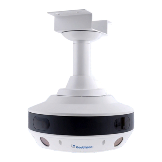
Page 9: Installation
2. Installation GV-SV48000 can be mounted on the ceiling using the supplied Straight Tube Mount: GV-Mount103-1. Make sure the ceiling has enough strength to support the camera and the mount. Required items: • Screws for ceiling x 4 (Self-prepared) • Micro SD card x 4 (Self-prepared) •... - Page 10 On the back of the camera, use a screwdriver to remove the 5 screws on the back plate and remove the plate. Insert a Micro SD card to each of the SD card slots. The labels correspond to the camera numbers labeled on the back of the camera.
- Page 11 Installation Rotate and secure the 3 rivets onto the back plate in the holes labeled with either a triangular or circular symbol. Circular Triangular Note: Secure all rivets in the holes with the same symbol. The arrow on the mounting cap will align with the corresponding triangular or circular symbol located between Camera Number SD_A and SD_D after Step 10.
-
Page 12: Connecting The Camera
3. Connecting the Camera The GV-SV48000 comes with a data cable that allows you to connect to the power adapter, microphone, speaker, and any I/O devices. Follow the steps below to connect the camera. Connect Power using one of the following methods: •... - Page 13 Connecitng the Camera Connecting the GV-PA901 PoE Adapter Connect one end of an Ethernet cable to the LAN 10 / 100 port on the GV-PA901 and the other end to a Hub / Router. Connect one end of an Ethernet cable to the PoE 10 / 100 port on the GV-PA901, and the other end to the GV-SV48000 camera.
-
Page 14: Accessing Gv-Sv48000
4. Accessing GV-SV48000 4.1 Web Browser Once installed, your camera is accessible over the network. Make sure your network connection is active, and the following requirements are met. 64-bit Windows 7 / 8 / 8.1 / 10 / Server 2008 R2 / Server 2012 R2 •... -
Page 15: Checking The Dynamic Ip Address
IP address. Follow the steps below to look up its IP address. Download and install the GV-IP Device Utility program from the GeoVision website. Note: The PC installed with GV-IP Device Utility must be under the same LAN as the camera you wish to configure. -
Page 16: Configuring The Ip Address
4.3 Configuring the IP Address Follow the steps below to configure the IP address for each of the 4 IP cameras in GV-SV48000 and avoid IP conflict with other GeoVision devices. 1. On the GV-IP Utility window, click the button to search for the IP devices connected in the same LAN. - Page 17 Accessing GV-SV48000 4. To assign a new IP address, click Network and select LAN. 5. Select Static IP address. Type IP Address, Subnet Mask, Router/Gateway, Primary DNS and Secondary DNS in the LAN Configuration section. 6. Click Apply. The camera is now accessible by entering the assigned IP address on the Web browser.
-
Page 18: The Integrated Web Interface
5. The Integrated Web Interface 5.1 Expansive Mode To access live view, log in the Web interface as described in Step 1 ~ 3, 4.3 Configuring the IP Address, click Live View and select Expansive Mode. This mode enables the display of all cameras on the same screen. -
Page 19: Camera Settings
The Integrated Web Interface 5.2 Camera Settings The cameras installed on GV-SV48000 must be accessed and configured individually under Camera Settings on the left menu of its Web interface. However, you can only access the following settings through GV-SV48000 (Main Config), and all changes made on the Main page will apply to all cameras: Monitoring Recording Schedule >... -
Page 20: Upgrading System Firmware
6. Upgrading System Firmware GeoVision periodically releases the updated firmware on GeoVision website. To load the new firmware into the GV-SV48000 Camera, follow the instructions below. 1. On the GV-IP Device Utility window, click on the IP address of your GV-SV48000 and select Configure to show the IP address belonging to each of the 4 IP cameras. -
Page 21: Restoring To Factory Default
7. Restoring to Factory Default If for any reason the camera is not responding correctly, you can reset it to its factory default setting by using the camera’s Web interface or by operating directly on the camera. 7.1 Using the Web Interface 1.
Need help?
Do you have a question about the GV Series and is the answer not in the manual?
Questions and answers