Table of Contents

Related Manuals for GeoVision GV-IP Series


Summary of Contents for GeoVision GV-IP Series
- Page 1 GV-IP Speed Dome User's Manual GV-SD2322-IR GV-SD2722-IR GV-SD3732-IR GV-SD4825-IR GV-SD4834-IR Before attempting to connect or operate this product, please read these instructions carefully and save this manual for future use. ISD-UM-D...
- Page 2 GeoVision. Every effort has been made to ensure that the information in this manual is accurate. GeoVision, Inc. makes no expressed or implied warranty of any kind and assumes no responsibility for errors or omissions. No liability is assumed for incidental or consequential damages arising from the use of the information or products contained herein.
- Page 3 Preface Welcome to the GV-IP Speed Dome User’s Manual. The features described in the manual vary among camera models and versions. Some features may not be available in your camera. This Manual is designed for the following models and firmware versions: Model Model Number Firmware Version...
-
Page 4: Table Of Contents
Contents Naming Definition ..............vi Note for Connecting to GV-VMS / DVR / NVR .......vi Note for Recording ..............vi Note for Installing Camera Outdoor ........vii Note for Face Detection ............viii Note for People Counting ............ix Chapter 1 Introduction ............1 1.1 Packing List ......................2 1.2 System Requirements .................... - Page 5 Chapter 4 Administrator Mode ...........31 4.1 Common .......................34 4.1.1 Navigation / Basic Info ................34 4.1.2 Local Settings ..................35 4.2 Network ........................37 4.2.1 Network ....................37 4.2.2 DNS ......................39 4.2.3 Port ......................39 4.2.4 Port Mapping ....................40 4.2.5 DDNS .......................41 4.2.6 E-mail .......................42 4.2.7 SNMP .......................44 4.2.8 802.1x .......................45 4.2.9 QoS ......................46...
- Page 6 4.6.6 Object Left Behind ..................76 4.6.7 Face Detection..................77 4.6.8 People Counting ..................79 4.6.9 Auto Tracking ...................81 4.6.10 Attribute Collection ..................83 4.6.11 Advanced Settings ..................83 4.7 Events........................86 4.7.1 Motion Detection ..................86 4.7.2 Tampering Alarm ..................88 4.7.3 Audio Detection ..................89 4.7.4 Alarm Input ....................90 4.7.5 Alarm Output ....................91 4.7.6 Capture .....................92 4.7.7 Temperature Alarm ...................92...
- Page 7 Chapter 6 Advanced Applications ........113 6.1 Upgrading System Firmware ................113 6.1.1 Using the Web Interface ................. 114 6.1.2 Using the GV-IP Device Utility ..............115 6.2 Restoring to Factory Default Settings ..............116 6.2.1 Using the Web Interface ................. 116 6.2.2 Directly on the Camera ................
-
Page 8: Naming Definition
Naming Definition GV-DVR / NVR GeoVision Analog and Digital Video Recording Software. The GV-DVR also refers to GV-Multicam System or GV-Hybrid DVR. GV-VMS GeoVision Video Management System for IP cameras. Note for Connecting to GV-VMS / DVR / NVR The GV-IP Speed Dome is designed to work with and record on GV-VMS / DVR / NVR, a video management system. -
Page 9: Note For Installing Camera Outdoor
Note for Installing Camera Outdoor When installing the camera outdoor, be sure that: The camera is set up above the junction box to prevent water from entering the camera along the cables. Any power, audio and I/O cables are waterproofed using waterproof silicon rubber or the like. -
Page 10: Note For Face Detection
Note for Face Detection To use the camera’s built-in face detection feature (see 4.6.7 Face Detection), not supported by GV-SD2322-IR, it is recommended to install the camera according to the criteria listed below: Surveillance Condition • The camera shall be installed at a site with uniform, sufficient lighting, where the face(s) to be detected are fully illuminated. -
Page 11: Note For People Counting
Note for People Counting To use the camera’s built-in people counting feature (see 4.6.8 People Counting), not supported by GV-SD2322-IR, it is recommended to install the camera according to the criteria listed below: Surveillance Condition • The camera shall be installed at a site with uniform, sufficient lighting, where the person(s) to be counted are fully illuminated. -
Page 12: Chapter 1 Introduction
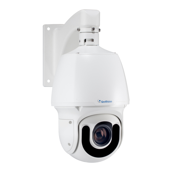
Introduction Chapter 1 Introduction GV-IP IR Speed Dome Series is an outdoor network PTZ camera that offers 22x / 25x / 33x optical zoom and unlimited digital zoom, capable of showing smooth live view with great details. This camera can simultaneously deliver three video streams in resolutions up to 1920 x 1080 at 30 fps (GV-SD2322-IR), 1920 x 1080 at 60 fps (GV-SD2722-IR), 2048 x 1536 at 30 fps and 1920 x 1080 at 60 fps (GV-SD3732-IR) or 2688 x 1520 at 30 fps (GV-SD4825-IR / GV-SD4834-IR). -
Page 13: Packing List
1.1 Packing List • • IR IP Speed Dome 24V AC Power Adapter (only for GV-SD2322- IR / SD2722-IR / SD3732-IR) • • M4 Hex Key Waterproof Rubber Set • Waterproof Guidelines • Download Guide... -
Page 14: System Requirements
Introduction 1.2 System Requirements Intel Core i5-4670, 3.40 GHz Memory DDR3 8 GB RAM On Board Graphics Intel HD Graphics 4600 (Versions of driver from year 2014 or later required) ⚫ Web Browsers Internet Explorer 11.0 or above ⚫ Google Chrome ⚫... -
Page 15: Optional Accessories
1.3 Optional Accessories Optional accessories can expand the capabilities and versatility of your GV-IP Speed Dome. Contact your dealer for more information. Model Number Name Details GV-Mount104 Straight Tube Kit Dimensions: 219 x 125 x 332 mm (8.6” x 4.9” x 13.1”) Weight: 1.8 kg (3.97 lb) Straight Tube and GV-Mount105... - Page 16 Introduction GV-Mount300-1 Convex Corner Dimensions: 238.6 x 395.2 x 210 mm Adapter Kit (9.4’’ x 15.5” x 8.2”) Weight: 4.27 kg (9.41 lb) GV-Mount310-1 Concave Corner Dimensions: 111.2 x 369.9 x 210 mm Adapter Kit (4.37’’ x 14.5” x 8.2”) Weight: 2.96 kg (6.53 lb) GV-Mount400-1 Pole Mount Bracket...
-
Page 17: Physical Description
1.4 Physical Description GV-SD2322-IR / SD2722-IR / SD3732-IR GV-SD4825-IR GV-SD4834-IR Figure 1-1 Name Function Resets all configurations to default factory settings. See Default Button 6.2 Restoring to Factory Default Settings. Micro SD Card Slot Inserts a micro SD card to store recording data. -
Page 18: Accessory Installation (Wall Pendant Mount)
Introduction 1.5 Accessory Installation (Wall Pendant Mount) You can separately purchase optional mounting accessories to mount your GV-IP Speed Dome on a wall, ceiling or pole. Make sure the wall is strong enough to support the camera and the mount. Required Items •... - Page 19 Insert the micro SD card into the slot, and secure the back cover of the camera. For GV-SD2322-IR / SD2722-IR / SD3732-IR Figure 1-5 For GV-SD4825-IR For GV-SD4834-IR Figure 1-6 Figure 1-7 Note: Be sure to format the memory card on the camera’s Web interface. See 4.8 Storage for details.
- Page 20 Introduction Place the pendant tube on the wall, and mark the position of the screw holes. Figure 1-8 Drill holes on the wall, and secure the pendant tube to the wall with 4 self-prepared screws. Attach the safety lock of the camera to the pendant tube. Figure 1-9 Thread the data cable through the pendant tube.
- Page 21 Attach the camera to the pendant tube, rotate the camera until it is locked into position, and secure the indicated screws. Figure 1-11 Insert the pendant mount screws and tighten with the supplied M4 hex key. Figure 1-12 Thread the Ethernet cable through the waterproof rubber set as shown below. Figure 1-13 Note: The size of RJ-45 connector must be within 14 mm to go through the waterproof rubber set.
-
Page 22: Connecting The Camera
Introduction 1.6 Connecting the Camera The camera comes with a data cable that allows you to connect the camera to the power adapter, microphone, speaker, and I/O devices. Video Out (BNC) Audio In Alarm In Audio Out Alarm Out RS-485 (not available for GV-SD2322-IR) Ethernet Power (not applicable for GV-SD4825-IR) Power adapter (only applicable for GV-SD4825-IR) - Page 23 Wire Definition GV-SD2322-IR / SD2722-IR / SD3732-IR No. Wire Definition Brown Audio In Brown / White Green Audio Out Green / White Gray Alarm In 1 Purple Alarm In 2 Black Orange Alarm In - Orange / White Alarm Out + RS-485 –...
- Page 24 Introduction Power cable The power loss in watts on the cable for different lengths and different core diameters is listed below. Core Diameter (Unit: mm) Distance 0.80 1.00 1.25 2.00 (Unit: m) Power (Unit: W) Note: Data listed above is applicable to copper cables that use AC 24V / DC 24V power supply.
-
Page 25: Chapter 2 Accessing The Camera
Chapter 2 Accessing the Camera Once installed, the IP Speed Dome is accessible on a network. Follow these steps to configure the network settings and access your surveillance images. 2.1 Installing on a Network These instructions describe the basic connections to install the camera on the network. 1. -
Page 26: Checking The Dynamic Ip Address
Accessing the Camera 2.1.1 Checking the Dynamic IP Address Download and install the GV-IP Device Utility program from the company website. Note: The PC installed with GV-IP Device Utility must be under the same LAN as the camera you wish to configure. Multilingual Web interface is NOT supported by GV-SD2322-IR. -
Page 27: Assigning An Ip Address
2.1.2 Assigning an IP Address To assign a new static IP address, log in the Web interface to access the network setting page. Note: If your router does not support DHCP, the default IP address will be 192.168.0.10. In this case, it is highly recommended that you modify the IP address to avoid IP address conflict with other GV-IP devices on the same LAN. -
Page 28: Accessing Live View
Accessing the Camera 2.2 Accessing Live View After logging in to the speed dome, you will see the Home page as shown below: Figure 2-3... -
Page 29: The Live View Window
2.2.1 The Live View Window For GV-SD2322-IR Figure 2-4 No. Name Function Set the display ratio of the image. • Scale: display images by 16:9. Proportional • Stretch: display images by window size. • Original: display images in its original size. Select a live video stream: main stream, sub stream or third Live Stream stream. - Page 30 Accessing the Camera Adjust the microphone volume on the PC during audio Microphone communication between the PC and the camera. Snapshot Take a snapshot of the current image displayed on the PC. Local Recording Start or stop local recording. Audio Start or stop audio communication between the PC and...
- Page 31 For GV-SD2722-IR / SD3732-IR / SD4825-IR / SD4834-IR Figure 2-5 No. Name Function Image Open the image setting page. -- See 4.5.1 Image. Two-way Audio Start or stop two-way audio. Start or stop area focus. By activating this function, you can set the camera focus based on a defined area of the live view.
- Page 32 Accessing the Camera Start or stop face snapshot. By activating this function, the camera takes face snapshots, and Face Snapshot displays them on the right of the live view window. Before (only applicable to activating this function, you must enable Face Detection - See GV-SD4825-IR / 4.6.7 Face Detection.
-
Page 33: Chapter 3 Ptz Control Panel
Chapter 3 PTZ Control Panel In this chapter, you will be guided through the various functions of PTZ Control Panel. The PTZ Control Panel is accessed from the live view interface of the camera. 3.1 Assessing the PTZ Control Panel Figure 3-1 No. - Page 34 PTZ Control Panel Select a preset and the camera goes to the selected preset. Preset -- See 3.1.1 Setting Presets. Patrol Select a patrol route. -- See 3.1.2 Setting Patrol.
-
Page 35: Setting Presets
3.1.1 Setting Presets You can create and delete preset points by clicking Preset on the control panel of Live View. Adding a Preset 1. Select Preset (No.7, Figure 3-1) on the control panel, and adjust the dome view to the desired direction, zoom and focus. -
Page 36: Setting Patrol
PTZ Control Panel 3.1.2 Setting Patrol A patrol route is the track by which the camera follows when moving from a preset to the next. The length of time that the camera stays at each preset is configurable. Multiple patrol routes are allowed for the camera. - Page 37 Note: 1. It is recommended that the first action type is Go to Preset. 2. If Keep Rotating is selected, the camera will rotate at the set speed and zoom in the set direction or position for a certain amount of time. Recording a Patrol Route You can record the dome movements of the camera as a patrol route.
- Page 38 PTZ Control Panel Starting a Patrol Route After you have added a patrol route, you can start patrolling by clicking on the control panel. Figure 3-8...
- Page 39 Editing a Patrol Route On the control panel, click to modify the ID, name and dome movement of an existing patrol route. Figure 3-9 Delete a Patrol Route On the control panel, click for a patrol route and confirm the delete. Figure 3-10...
- Page 40 PTZ Control Panel Making a Patrol Plan You can set up the camera to perform different patrol routes at different time periods throughout the week by making a patrol plan. 1. On the control panel, click the Patrol Plan button to set the correct patrol time and route.
-
Page 41: Setting Home Position
3.2 Setting Home Position The PTZ camera will return to home position if no operation is made within a specified period. 1. On the Setup page, select PTZ in the left menu and select Home Position to access the settings. Figure 3-12 2. -
Page 42: Chapter 4 Administrator Mode
Administrator Mode Chapter 4 Administrator Mode The Administrator can access and configure GV-IP Speed Domes through the network. Click Setup at the top of the Web interface to access the following nine configuration tabs: Common, Network, Video & Audio, PTZ, Image, Intelligent, Events, Storage, Security and System. - Page 43 List of Options See the table below for the settings available on the Web interface. Find the topic of interest by referring to the section number prefixed to each option. The configuration tabs and settings may vary with different models. IMPORTANT: The available functions may vary among camera models and firmware versions.
- Page 44 Administrator Mode 4.6.1 Smart Settings 4.6.2 Cross Line 4.6.3 Enter / Leave Area 4.6.4 Intrusion 4.6.5 Object Removed 4.6 Intelligent 4.6.6 Object Left Behind 4.6.7 Face Detection 4.6.8 People Counting 4.6.9 Auto Tracking 4.6.10 Attribute Collection 4.6.11 Advanced Settings 4.7.1 Motion Detection 4.7.2 Tampering Alarm 4.7.3 Audio Detection 4.7.4 Alarm Input...
-
Page 45: Common
4.1 Common Under the Common tab, the Administrator can find the general settings for the camera, as well as shortcuts to the following setting pages. ◼ TCP/IP / Ethernet: See 4.2.1 Network for details. ◼ Time: See 4.10.1 Time for details. ◼... -
Page 46: Local Settings
Administrator Mode 4.1.2 Local Settings You can set local parameters for your PCs. Figure 4-3 [Intelligent Mark] ◼ Untriggered Target: Displays the detection lines / areas defined by Smart Settings on Live View. You must set up Smart Settings first for this function to work, see 4.6 Intelligent. - Page 47 [Video] ◼ Processing Mode (for GV-SD2722-IR / SD3732-IR) Real Time Prior / Real Time Priority: Select this if the network is in good condition. Fluent Prior / Fluency Priority: Select this if you want short time lag for live video. ...
-
Page 48: Network
Administrator Mode 4.2 Network The network section allows you to configure the network settings, modify ports, configure FTP server, and set up e-mail for notification. 4.2.1 Network Figure 4-4 ◼ IP Obtain Mode / Obtain IP Address: Select Static IP, PPPoE or DHCP according to your network environment. - Page 49 Static IP address: Assign a static IP or fixed IP to the camera. Type the camera’s IP address, Subnet Mask, Router/Gateway, Preferred DNS server and Alternate DNS server. Parameters Default IP address 192.168.0.10 Subnet Mask 255.255.255.0 Router/Gateway 192.168.0.1 Preferred DNS server 8.8.8.8 Alternate DNS server 8.8.4.4...
-
Page 50: Dns
Administrator Mode 4.2.2 DNS Type the camera’s Preferred DNS Server and Alternate DNS Server. For GV-SD2322-IR, you can find the same setting in TCP / IP of the left menu. Figure 4-5 4.2.3 Port You can modify the default HTTP port, HTTPS port and RTSP port if necessary. Figure 4-6... -
Page 51: Port Mapping
4.2.4 Port Mapping Note this function is NOT applicable to GV-SD2322-IR. This function can automatically forward and open certain ports on your router, allowing connection to your camera from the Internet. Figure 4-7 1. Enable Port Mapping, and select Mapping Type. 2. -
Page 52: Ddns
DHCP Server or ISP (in xDSL connection) has changed. Before enabling the DDNS function, the Administrator should apply for a Host Name from the DDNS service provider’s website. There are 2 providers listed in the camera: GeoVision GVDIP, GeoVision DDNS Server and DynDNS.org. -
Page 53: E-Mail
4. In the Geovision DDNS Server page, type a desired Hostname and Password. Re-type Password and type the verification letters shown in the image. Click Send. 5. In the Web interface of your camera, type Username. The username is the hostname registered in DDNS Server. - Page 54 Administrator Mode [Sender] 1. Type the Name and Address of the sender. 2. Type the SMTP Server. 3. Type the SMTP Port number. 4. To send the e-mail through TLS / SSL encryption, enable TLS / SSL. 5. Enable Attach Image to include 3 instant snapshots as attachment in the e-mail according to the Snapshot Interval (s) specified.
-
Page 55: Snmp
4.2.7 SNMP Note this function is NOT applicable to GV-SD2322-IR. Users can transfer the configurations of the device through SNMP protocol to communicate with and/or integrate it into a central server. Figure 4-12 ◼ SNMP Type: Select the type of SNMP desired, between SNMPv3 and SNMPv2. ◼... - Page 56 Administrator Mode 4.2.8 802.1x Note this function is NOT applicable to GV-SD2322-IR. IEEE 802.1x is an IEEE standard for port-based Network Access Control. It provides an authentication mechanism to devices connecting to a LAN or WLAN. Figure 4-13 1. Enable IEEE 802.1x. 2.
-
Page 57: Qos
4.2.9 QoS Note this function is NOT applicable to GV-SD2322-IR. QoS is the prioritization of network traffic used to ensure resource reservation under abundant data flow. Figure 4-14 ◼ Audio & Video: Optionally modify the priority of value of Audio & Video. The higher the value, the higher the priority. -
Page 58: Video & Audio
Administrator Mode 4.3 Video & Audio This section allows you to configure the three video streams, as well as audio settings. 4.3.1 Video You can set video parameters that your camera supports and view the current status of BNC output. You may also enable the sub-stream and third stream as needed. Figure 4-15 The following options are available for the main, sub and third streams. - Page 59 ◼ Bit Rate: ◼ CBR: The camera transmits data at a constant data rate by varying the quality of the stream ◼ VBR: The quality of the video stream is kept as constant as possible at the cost of a varying bitrate.
-
Page 60: Audio
Administrator Mode 4.3.2 Audio You can configure the audio settings of the camera. Figure 4-16 The following options are available. ◼ Audio Input: Select ON to enable audio input.\ ◼ Input Gain: Set the audio signal amplification for sampling. The greater the gain, the greater amplification ◼... -
Page 61: Snapshot
4.3.3 Snapshot This function is NOT applicable to GV-SD2322-IR. Using the Snapshot function, when an alarm is triggered, the camera will automatically upload the captured snapshots to the FTP server or send snapshots to the specified e-mail address. Note: If Upload Images is selected in Figure 4-66, 4.8.3 FTP, the captured snapshots will only be sent to the FTP server. -
Page 62: Roi
Administrator Mode 4.3.4 ROI When Region of Interest (ROI) is enabled, the system ensures image quality for ROI first if the bit rate is insufficient. Note this function is NOT applicable to GV-SD2322-IR. Figure 4-18 Click to enable and add ROI. Click and drag on the image to specify an area. -
Page 63: Media Stream
4.3.5 Media Stream Note this function is NOT applicable to GV-SD2322-IR. Media Stream By configuring media stream, you can set the camera to transmit code streams by UDP or TCP protocol to a specified IP address and port number. The settings can be saved and take effect after the camera is restarted. - Page 64 Administrator Mode RTSP Multicast Address After an RTSP multicast address is configured, the third-party player can request the RTSP multicast media stream from the camera through the RTP protocol. Figure 4-20 1. Type the Multicast Address (224.0.0.0 to 239.255.255.255) and Port number (0 to 65535).
-
Page 65: Ptz
4.4 PTZ 4.4.1 Basic Settings Note this function is NOT applicable to GV-SD2322-IR. Basic settings allows you to configure basic PTZ settings related to the camera’s preset, memory card, timeout, and more. Figure 4-21 4.4.2 Home Position You can set the camera to return to home position if no operation is made within a specified period. -
Page 66: Ptz Limit
Administrator Mode 4.4.3 PTZ Limit Users can set PTZ limitations to prevent the camera from hitting obstacles such as walls. Note this function is NOT applicable to GV-SD2322-IR. Figure 4-22 1. Click Start PTZ Limit to enable the function. 2. Adjust the dome view in such a way that it reaches the PTZ limit you want to set. 3. -
Page 67: Remote Control
4.4.4 Remote Control Note this function is NOT applicable to GV-SD2322-IR. You can connect a third-party PTZ remote control program to your GV-IP Speed Dome once this function is enabled. Figure 4-23 1. Specify the Listener Port to which the third-party PTZ remote control program connects. 2. -
Page 68: Patrol
Administrator Mode 4.4.5 Patrol Note this function is NOT applicable to GV-SD2322-IR. You can set the camera to take a snapshot and upload the image to the FTP server when the camera goes to the preset during the patrol route. Figure 4-24 1. -
Page 69: Orientation
4.4.6 Orientation Note this function is only applicable to GV-SD4825-IR / 4834-IR. You can manually set a north direction or home position for the camera. Figure 4-25 [Orientation] ◼ Set as north: After the camera is positioned to a specific direction, the position will be set as the north direction. -
Page 70: Image
Administrator Mode 4.5 Image This section introduces the Image Settings, On-screen Display, Privacy Mask, and Quick Focus. 4.5.1 Image This page allows you to adjust image settings such as brightness, exposure, IR illumination and white balance. Figure 4-26 [Scene] ◼ Current: Indicates the scene that is being used. - Page 71 Figure 4-27 [Image Enhancement] ◼ Brightness: Adjust the degree of brightness of the image. ◼ Saturation: Adjust the amount of a hue contained in a color. ◼ Contrast: Set the degree of difference between the blackest pixel and the whitest pixel. ◼...
- Page 72 Administrator Mode Figure 4-28 [Exposure] ◼ Exposure Mode: Select the correct exposure mode to achieve the desired exposure effect. The default setting is Outdoor with a frequency of 50 Hz. ◼ Shutter (s): The length of time that allows light to enter the lens. You can set a shutter speed when Exposure Mode is set to Manual (Custom) or Shutter Priority.
- Page 73 ◼ Slow Shutter: Improve image brightness in low light conditions. For GV-SD2322-IR, you can only set this parameter when Exposure Mode is not set to Shutter Priority and when Image Stabilizer is disabled. ◼ Slowest Shutter: Set the slowest shutter speed that the camera can use during exposure.
- Page 74 Administrator Mode Figure 4-29 [Smart Illumination] ◼ Smart Illumination: Select Enable to adjust the IR illumination settings. ◼ Control Mode: Global Mode: (The function is only applicable to GV-SD2322-IR.) Adjust IR illumination and exposure to achieve balanced image effects. Some areas might be overexposed if you select this option.
- Page 75 Figure 4-30 [Focus] ◼ Focus Mode: Auto Focus: Focuses automatically according to the current light condition. Manual Focus: Manually adjust camera focus as required. One-Click Focus: The camera is triggered to focus once when rotating, zooming or going to a preset.
- Page 76 Administrator Mode Figure 4-31 [White Balance] ◼ White Balance: Adjust the red or blue offset of the image. Auto: Adjust the red and blue offset automatically according to the light condition (the color tends to be blue). Outdoor: (The function is NOT applicable to GV-SD2322-IR). It is recommended for outdoor scenes with a wide range of color temperature variation.
-
Page 77: Osd
4.5.2 OSD On Screen Display (OSD) is the text displayed on the screen with video images and may include time and other customized contents. For GV-SD2322-IR Figure 4-33 1. Click under Position to select an Area #, and then click Overlay OSD Content to select the content to display on screen. - Page 78 Administrator Mode 3. Under Display Style, customize the text style and date/time format. 4. Under Orientation, use the Direction drop-down list to select a direction, turn the camera toward the corresponding direction, and click Demarcate. After you have set the position and OSD content, the symbol appears in the Status column, which means that the OSD is set successfully.
-
Page 79: Privacy Mask
4.5.3 Privacy Mask On certain occasions, you may need to set a mask area to block out parts of the camera image to protect privacy, for example, the keyboard of an ATM machine. When PTZ changes its position or zooms, the Privacy Mask will be adjusted accordingly to protect the area all along. -
Page 80: Quick Focus
Administrator Mode 4.5.4 Quick Focus Note this function is only applicable to GV-SD4825-IR / SD4834-IR. Quick Focus allows you to calibrate your lens with demarcate lines within a specified area. Figure 4-37... -
Page 81: Intelligent
4.6 Intelligent Note this function is NOT applicable to GV-SD2322-IR. The Intelligent functions allow the camera to track moving people and/or object in a predefined area and trigger alarms, such as when the person trespasses a detection threshold, or attempts to breach into a detection zone set. Enabling the Auto Tracking function causes other Intelligent functions to be disabled and vice versa. -
Page 82: Cross Line
Administrator Mode 4.6.2 Cross Line Cross line detection generates an alarm when an object moves past the detection threshold in the direction you defined. Up to 4 detection lines can be added. Note that when adding multiple detection lines, make sure they do NOT intersect as it may affect the detection results. - Page 83 Select Upload to FTP and/or Send E-mail under Trigger Actions to automatically upload snapshots to the specified FTP server and/or send snapshots to the specified e-mail address upon the video analytic events. Select A -> 1 to trigger an output device after alarm output is triggered by a motion detection alarm, temperature alarm or input alarm.
-
Page 84: Enter / Leave Area
Administrator Mode 4.6.3 Enter / Leave Area Enter Area detection detects objects that enter a specified area, while Leave Area detection detects objects that leave a specified area. Alarms are triggered when such an event is detected. Note this function is only applicable to GV-SD4825-IR / SD4834-IR. Figure 4-41 1. -
Page 85: Intrusion
4.6.4 Intrusion With Intrusion Detection, an alarm is generated when an object enters the boundaries of the detection area. Up to 4 detection areas can be added. Note that it is recommended NOT to overlap the detection areas when adding multiple detection areas. Select the checkbox next to Intrusion to enable and click to configure. -
Page 86: Object Removed
Administrator Mode Filter Type: Set the type and size of the object to trigger the detection. 4. For Trigger Actions and Plan, follow Step 5 ~ 6, 4.6.2 Cross Line. 4.6.5 Object Removed Object Removed can generate an alarm when an object is removed from the specified area. Up to 4 detection areas can be added. -
Page 87: Object Left Behind
4.6.6 Object Left Behind With Object Left Behind, an alarm can be generated when an object which remained in the detection area for the specified period of time, leaves the specified region. Up to 4 detection areas can be added. Note that it is recommended NOT to overlap the detection areas when adding multiple detection areas. -
Page 88: Face Detection
Administrator Mode 4.6.7 Face Detection The Face Detection function can detect for and capture faces to be sent to an FTP server. Select the checkbox next to Face to enable and click to configure. Figure 4-45 Once enabled, define the detection area, either by selecting Specified Area and drawing a desired area on the image, or select Full Screen to set the entire image as detection area. - Page 89 Min. Pupillary Distance (px): Click Draw and draw in the live view window. Counting: To count the number of people entering / exiting in the detection area, enable this function. To display the counting results in the live view window, select People Counting in OSD settings.
-
Page 90: People Counting
Administrator Mode 4.6.8 People Counting The People Counting function can count the number of person(s) entering and leaving the vicinity, which is useful at an entrance/exit setting. Select the checkbox next to People Counting to enable and click to configure. For GV-SD2722-IR / SD3732-IR Figure 4-46 1. - Page 91 For GV-SD4825-IR / SD4834-IR Figure 4-47 1. Once enabled, draw a detection line and define the entrance direction. Select the entrance direction from the Enter drop-down list. 2. Select the desired Counting Type, from Total, People Entered or People Left. When any of the People Present Alarms is enabled, this function will not be available.
-
Page 92: Auto Tracking
Administrator Mode 4.6.9 Auto Tracking Auto Tracking allows you to track moving objects for as long as 300 seconds. There are certain limitations that cause ineffective tracking: • Number of the targets: The camera can only track one person at a time. When more than one people walks into the detection area, only the first person entering the scene is tracked. - Page 93 For GV-SD4825-IR / SD4834-IR Figure 4-49 1. Enable Auto Tracking. 2. Set Tracking Object, Filter Type, Max. Size, and Min. Size. 3. Click Tracking for other setting options, see 4.6.11 Advanced Settings for details.
-
Page 94: Attribute Collection
Administrator Mode 4.6.10 Attribute Collection Note this function is only applicable to GV-SD4825-IR / 4834-IR. Attribute Collection allows you to define the face attributes for the camera to collect, including gender, age range, glasses or mask. Figure 4-50 Note: To display the attributes on the live view window, make sure to enable Display Attributes in Local Parameters. - Page 95 Note: Make sure to turn off Face Detection before setting Photo Parameters. Detection Parameters For GV-SD2722-IR / SD3732-IR Figure 4-52 ◼ Detection Mode: Choose between Normal Mode, which detects for moving targets continuously, and Filter Repeat Motion Mode, which ignores repeated motions. For GV-SD4825-IR / SD4834-IR Figure 4-53 ◼...
- Page 96 Administrator Mode Tracking Note this function is only applicable to GV-SD4825-IR / 4834-IR. Figure 4-54 ◼ Continuously Track: Enable this function for round-the-clock tracking. ◼ Tracking Timeout(s): Type the amount of time for the camera to keep tracking moving objects. ◼...
-
Page 97: Events
4.7 Events You can set the camera to generate an alarm upon motion detection, temperature alarm, audio alarm, and input trigger. 4.7.1 Motion Detection Motion detection is used to generate an alarm whenever movement occurs in the specified area. Figure 4-55 1. - Page 98 Administrator Mode ◼ Clear alarm: After an alarm is triggered, ⚫ If the same alarm is not triggered within the set time, the alarm will be cleared and the same alarm can be reported again. ⚫ If the same alarm is triggered within the set time, the alarm will not be cleared until the suppress alarm time expires.
-
Page 99: Tampering Alarm
4.7.2 Tampering Alarm Note this function is only applicable to GV-SD2722-IR / 3732-IR. Tampering alarm is used to detect when the camera is being physically tampered with. An alarm can be generated when the camera is moved, covered up, or out of focus. Figure 4-56 1. -
Page 100: Audio Detection
Administrator Mode 4.7.3 Audio Detection The camera can detect for abnormal audio volume. When the rise or fall of volume exceeds the set limit, or when the input volume reaches the threshold, the camera reports an alarm and triggers the set actions. Make sure an audio input device is correctly connected to the camera and audio input is enabled. -
Page 101: Alarm Input
4.7.4 Alarm Input The camera can receive alarm information from an input device. Figure 4-58 1. Select Alarm Input 1 or Alarm Input 2 from the drop-down list. 2. Type an Alarm Name, and set an alarm ID. 3. Select Normally Open / N.O or Normally Closed / N.C according to the type of the alarm input device. -
Page 102: Alarm Output
Administrator Mode 4.7.5 Alarm Output After alarm output is triggered by a motion detection alarm, temperature alarm or input alarm, the camera can trigger an output device. Figure 4-59 Type and Alarm Name for the output device. Set the status to Normally Open (default setting). Set the alarm duration. -
Page 103: Capture
4.7.6 Capture Note this function is only for GV-SD2322-IR. Using the Capture function, when an alarm is triggered, the camera will automatically upload the captured snapshots to the FTP server or send snapshots to the specified email address. For more detailed instructions, refer to 4.3.3 Snapshot under Video & Audio. 4.7.7 Temperature Alarm Note this function is only for GV-SD2322-IR. -
Page 104: Storage
Administrator Mode 4.8 Storage This section allows you to configure memory card settings and download recorded videos. 4.8.1 Storage After inserting a memory card, you need to reboot the camera and refresh the Web interface. You can configure the storage settings on the Storage page. [Storage] Figure 4-62 ◼... - Page 105 ◼ Storage Policy: Choose the Storage Policy from the three options. Manual and Alarm Recording: Manually start recording and upon input-triggered events. Scheduled and Alarm Recording: Start recording by schedule and upon input- triggered events. Alarm Recording Only: Start recording upon input-triggered events. Note: The file size of more than 500 MB is required to create one recording file.
-
Page 106: Recording Download
Administrator Mode 4.8.2 Recording Download You can search and download the recorded videos stored in the memory card. Select a time period to search for video, and click Search. The search results are shown. Figure 4-65 To download the videos, select the files and click Download. To open the folder for storing recordings, click Open. -
Page 107: Ftp
4.8.3 FTP After the configuration of FTP, you will be able to upload snapshots from the camera to the specified FTP server. General Figure 4-66 1. Type the Server IP address. 2. Change the Port No. of the FTP server if needed. 3. - Page 108 Administrator Mode Note: 1. To upload snapshots, make sure to enable Snapshot in Video & Audio. For more detailed instructions, refer to 4.3.3 Snapshot. 2. If Overwrite Storage is not selected and the storage is full, snapshots can no longer be taken.
- Page 109 Video Note this function is only applicable to GV-SD4825-IR / SD4834-IR. This function is used to store recordings shot for smart functions such as face detection. Figure 4-68 For functions under Server Parameters, refer to Step 1~3, Intelligent above for details. Under Save To Root Directory, select a directory in which to save the recordings, or select Custom to name a storage folder on the FTP server.
-
Page 110: Backing Up Storage
Administrator Mode 4.8.4 Backing Up Storage Note this function is only applicable to Internet Explorer browsers. In the Photo setting, you can back up the existing videos and snapshots to your local PC. Figure 4-69 1. Select Photo at the top of the Web interface and click Refresh. 2. -
Page 111: Security
4.9 Security Note these functions are NOT for GV-SD2322-IR. This section allows you to create user accounts and set the network security settings. 4.9.1 User There are two types of accounts: Administrator and Common User. ◼ Administrator: The default name of the administrator is admin, which cannot be modified. - Page 112 Administrator Mode HTTPS You can enable the Hypertext Transfer Protocol Secure (HTTPS) settings to access the camera through a secure protocol. Click Enable and click Save. Figure 4-71 RTSP Authentication RTSP (Real Time Streaming Protocol) is an application layer protocol for transmitting audio and video.
- Page 113 IP Address Filtering You can allow or deny the access from the specified IP address to your camera. Figure 4-74 1. Enable IP Address Filtering. 2. Choose a Filtering Mode: Allow Access / Whitelist or Deny Access. 3. Click + to add an IP address. 4.
- Page 114 Administrator Mode For GV-SD4825-IR / SD4834-IR Illegal Login Lock By enabling Illegal Login Lock, the camera will apply a 5-minute account lockout duration after 5 failed login attempts. Figure 4-76...
-
Page 115: System
4.10 System This section allows you to create user accounts, set the camera time, and update the firmware. 4.10.1 Time You can use the following methods to adjust the system time of your camera. Figure 4-77 To manually set a time or synchronize with the computer time: Enable Time Sync (For GV-SD2322-IR Only) Select a Sync Mode. -
Page 116: Server
Administrator Mode Enable NTP. Type the IP address of the network time server next to NTP Server IP. Click Save. 4.10.2 Server Note this function is NOT applicable to GV-SD2322-IR. Server allows you to quickly access the FTP setting page. Click the FTP button to go to the FTP settings page and complete the storage settings. -
Page 117: Maintenance
4.10.4 Maintenance This section allows you to upgrade firmware, restart the camera, and backup/import camera configurations. Figure 4-80 [Firmware Upgrade / Software Upgrade]. For detailed instructions, refer to 6.1 Upgrading System Firmware and 6.1.1 Using the Web Interface. [Config Management] Export the current configurations of the camera and save them to the PC or an external storage medium. - Page 118 Administrator Mode [Focus] The device can adjust the speed of auto-focus according to the minimum focus distance. It is recommended that the minimum focus distance is set shorter than the distance between the objects and lens. For example, if the minimum focus distance is 3 m, then the objects within 3 m from lens will be out of focus.
-
Page 119: Ports And Device
4.10.5 Ports and Device Note this function is NOT applicable to GV-SD2322-IR. Use the RS485 serial port to transmit data to a third-party device. Figure 4-82 1. Select Trans-Channel / OSD / Local PTZ Control / Trans-Channel via ONVIF from the Port Mode drop-down list. -
Page 120: Log
Administrator Mode 4.10.6 Log Note this function is only applicable to GV-SD4825-IR / 4834-IR. Log allows you to inquire configurations made on the camera and export the information to the local PC. Figure 4-83 Set the start time and end time of the logs you want to query. Set the main log type, and click Query. -
Page 121: Chapter 5 Recording And Playback
Chapter 5 Recording and Playback The camera can record video and audio directly to the memory card. Note: See Note for Recording at the beginning of the manual. 5.1 Recording To configure the recording function, refer to the following sections •... -
Page 122: Playback From The Memory Card
Recording and Playback 5.2 Playback from the Memory Card You can play back the files recorded at the memory card of the camera from the Web interface. Click Playback at the top. This page appears. Figure 5-1 On the right, select a date and click Query (for GV-SD2322-IR / SD2722-IR / 3732-IR) or Search (for GV-SD4825-IR / SD4834-IR). - Page 123 Double-click a search result to play back the recorded file, or select the desired time on the Timeline at the bottom to play back the video from. You can also adjust the audio volume at the bottom-left corner if needed. Figure 5-3 The following functions are available: ◼...
-
Page 124: Chapter 6 Advanced Applications
Chapter 6 Advanced Applications This chapter introduces more advanced applications. 6.1 Upgrading System Firmware GeoVision periodically releases updated firmware on the company website. The new firmware can be loaded into the camera using the Web interface or the GV-IP Device Utility. -
Page 125: Using The Web Interface
6.1.1 Using the Web Interface Log into the Web interface and follow the steps below to update the firmware. 1. At the top, click Setup. In the left menu, select System and select Maintenance. This page appears. Figure 6-1 3. Click the Browse button to locate the firmware file (.zip) saved at your local computer. 4. -
Page 126: Using The Gv-Ip Device Utility
Advanced Applications 6.1.2 Using the GV-IP Device Utility You can upgrade the camera firmware using the GV-IP Device Utility. Note the computer used to upgrade firmware must be under the same network of the camera. 1. Download GV-IP Device Utility from the company website. Then follow the onscreen instructions to install the program. -
Page 127: Restoring To Factory Default Settings
6.2 Restoring to Factory Default Settings If for any reason the camera is not responding correctly, you can restore the camera back to its factory default settings using the Web interface or the Default Button on the camera. 6.2.1 Using the Web Interface To restore to default settings using the Web interface: 1. -
Page 128: Directly On The Camera
Advanced Applications 6.2.2 Directly on the Camera 1. Unscrew the back cover of the camera. For GV-SD2322-IR / SD2722-IR / For GV-SD4825-IR For GV-SD4834-IR SD3732-IR / SD4834-IR Figure 6-5 Figure 6-6 Figure 6-7 2. Press and hold the default button for about 30 seconds. For GV-SD2322-IR / SD2722-IR / SD3732-IR Figure 6-8... - Page 129 For GV-SD4825-IR For GV-SD4834-IR Figure 6-9 Figure 6-10 3. When the camera rotates twice, the process of loading default is completed and the camera robots automatically.
-
Page 130: Chapter 7 Vms / Dvr / Nvr Configurations
VMS / DVR / NVR Configurations Chapter 7 VMS / DVR / NVR Configurations The GV-VMS / DVR / NVR provides a complete video management solution, including video viewing, recording, playback, alert settings, and more. The integration specifications are listed below: •... -
Page 131: Setting Up Ip Cameras On Gv-Dvr / Nvr
7.1 Setting up IP Cameras on GV-DVR / NVR To set up the camera on the GV- DVR / NVR, follow these steps: On the main screen, click the Configure button, select System Configure, select Camera Install and click IP Camera Install. This dialog box appears. Figure 7-1 To automatically set up the camera, click Scan Camera to detect any camera on the LAN. - Page 132 VMS / DVR / NVR Configurations Click OK. This dialog box appears. Figure 7-3 Click OK. The camera is added to the connection list. Click the listed camera and select Display position to map the camera to a channel on the GV-DVR / NVR.
-
Page 133: Customizing The Basic Settings On Gv-Dvr / Nvr
7.1.1 Customizing the Basic Settings on GV-DVR / NVR After the camera is connected and assigned with a display position, you can configure the camera’s settings such as frame rate, codec type and resolution. Right-click the desired camera to see the following list of options: Figure 7-5 ◼... -
Page 134: Setting Up Ip Cameras On Gv-Vms
VMS / DVR / NVR Configurations 7.2 Setting Up IP Cameras on GV-VMS Follow the steps below to manually connect your camera to GV-VMS. 1. To access the IP Device Setup page, click Home , select Toolbar , click Configure and select Camera Install. - Page 135 4. Click OK. This dialog box appears. Figure 7-8 5. Click OK to add the camera to the list. 6. To connect the added camera, click the box besides the ID column. Upon successful connection, the Status icon shows green, with the video resolution and bit rate being displayed in the corresponding columns.
-
Page 136: Appendix
VMS / DVR / NVR Configurations Appendix A. RTSP Multicast Protocol Support The camera can support RTSP multicast protocol for both video and audio streaming. You can use the following RTSP multicast command to access the camera image: Stream 1: rtsp://<IP of the camera>/multicast/video1 Stream 2: rtsp://<IP of the camera>/multicast/video2 For example, rtsp://192.168.4.115/multicast/video1...
Need help?
Do you have a question about the GV-IP Series and is the answer not in the manual?
Questions and answers