Dell PowerEdge M420 Configuration Manual
Dell powerconnect m8024-k user's configuration guide
Hide thumbs
Also See for PowerEdge M420:
- Reference manual (1682 pages) ,
- Getting started manual (202 pages) ,
- Owner's manual (121 pages)

Related Manuals for Dell PowerEdge M420


Summary of Contents for Dell PowerEdge M420
- Page 1 Dell PowerConnect M6220, M6348, M8024, and M8024-k Switch User’s Configuration Guide Regulatory Models: PCM6220, PCM6348, PCM8024, and PCM8024-k...
-
Page 2: Notes And Cautions
Other trademarks and trade names may be used in this publication to refer to either the entities claiming the marks and names or their products. Dell Inc. disclaims any proprietary interest in trademarks and trade names other than its own. -
Page 3: Table Of Contents
Contents Introduction ..... . . About This Document ....Audience . - Page 4 Stacking Features (PCM6220 and PCM6348 Only) ..High Port Count ....Single IP Management ....Automatic Firmware Upgrade for New Stack Members .
- Page 5 Switching Features ....Flow Control Support (IEEE 802.3x) ..Head of Line Blocking Prevention .
- Page 6 Rapid Spanning Tree ....Multiple Spanning Tree ....Bridge Protocol Data Unit (BPDU) Guard .
- Page 7 Priority-based Flow Control (PFC) ..Internet Small Computer System Interface (iSCSI) Optimization ....Layer 2 Multicast Features .
- Page 8 Using Dell OpenManage Switch Administrator ..... About Dell OpenManage Switch Administrator ..Starting the Application ....
- Page 9 Recalling Commands from the History Buffer . . . Specifying Physical Ports ... . . Default Settings ....Setting the IP Address and Other Basic Network Information .
- Page 10 Configuring Static Network Information on the OOB Port ....Configuring Static Network Information on the Default VLAN ....Configuring and Viewing Additional Network Information .
- Page 11 Stack Port Summary ....Stack Port Counters ....Stack Port Diagnostics .
- Page 12 Default Management Security Values ..Controlling Management Access (Web) ..Access Profile ....Authentication Profiles .
- Page 13 Configuring HTTP and HTTPS Access ..Configuring DoS Information ... . Management Access Configuration Examples ..Configuring a Management Access List .
- Page 14 Log File ..... . Remote Log Server ....Email Alert Global Configuration .
- Page 15 Default General System Information ..Default Port Aggregator Configurations ..Configuring General System Settings (Web) ..System Information ....CLI Banner .
- Page 16 General System Settings Configuration Examples ......Configuring System and Banner Information . . . Configuring SNTP ....Configuring the Time Manually .
- Page 17 SNMP Configuration Examples ... . . Configuring SNMPv1 and SNMPv2 ..Configuring SNMPv3 ....13 Managing Images and Files .
- Page 18 14 Automatically Updating the Image and Configuration ... . Auto Configuration Overview ... . . What Is the DHCP Auto Configuration Process? .
- Page 19 sFlow Sampler Configuration ... . sFlow Poll Configuration ....Interface Statistics ....Etherlike Statistics .
- Page 20 ....How Does iSCSI Optimization Interact With Dell EqualLogic Arrays? ... What Occurs When iSCSI is Enabled or Disabled? .
- Page 21 Default Captive Portal Behavior and Settings ..Configuring the Captive Portal (Web) ..Captive Portal Global Configuration ..Captive Portal Configuration .
- Page 22 Default Port Values ....Configuring Port Characteristics (Web) ..Port Configuration ....Link Dependency Configuration .
- Page 23 Port Access Control Configuration ..Port Access Control History Log Summary ..Port Security ....Internal Authentication Server Users Configuration .
- Page 24 What Are the ACL Limitations? ..How Are ACLs Configured? ... . Configuring ACLs (Web) ....IP ACL Configuration .
- Page 25 ....VLAN Configuration Examples ... . . Configuring VLANs Using Dell OpenManage Administrator ... .
- Page 26 22 Configuring the Spanning Tree Protocol ......STP Overview ..... What Are Classic STP, Multiple STP, and Rapid STP? .
- Page 27 What is LLDP? ....What is LLDP-MED? ....Why are Device Discovery Protocols Needed? .
- Page 28 24 Configuring Port-Based Traffic Control ......Port-Based Traffic Control Overview ..What is Flow Control? .
- Page 29 25 Configuring L2 Multicast Features ..L2 Multicast Overview ....What Are the Multicast Bridging Features? ..What Is IP Multicast Traffic? .
- Page 30 Configuring L2 Multicast Features (CLI) ..Configuring Bridge Multicasting ..Configuring IGMP Snooping ... Configuring IGMP Snooping on VLANs .
- Page 31 Dot1ag L2 Ping ....Dot1ag L2 Traceroute ....Dot1ag L2 Traceroute Cache .
- Page 32 IPSG Interface Configuration ... IPSG Binding Configuration ... . IPSG Binding Summary ....DAI Global Configuration .
- Page 33 Configuring Link Aggregation (Web) ..LAG Configuration ....LACP Parameters ....LAG Membership .
- Page 34 30 Configuring Routing Interfaces ..Routing Interface Overview ....What Are VLAN Routing Interfaces? ..What Are Loopback Interfaces? .
- Page 35 Configuring the DHCP Server (Web) ... DHCP Server Network Properties ..Address Pool ....Address Pool Options .
- Page 36 Route Entry Configuration ... . . Configured Routes ....Route Preferences Configuration ..Configuring IP Routing Features (CLI) .
- Page 37 Configuring L2 and L3 Relay Features (CLI) ..Configuring L2 DHCP Relay ... . . Configuring L3 Relay (IP Helper) Settings ..Relay Agent Configuration Example .
- Page 38 Configuring OSPFv3 Features (Web) ..OSPFv3 Configuration ....OSPFv3 Area Configuration ... . OSPFv3 Stub Area Summary .
- Page 39 OSPF Configuration Examples 1003 ... . . Configuring an OSPF Border Router and Setting Interface Costs 1003 ....Configuring Stub and NSSA Areas for OSPF and OSPFv3 1005...
- Page 40 36 Configuring VRRP 1033 ....VRRP Overview 1033 ..... How Does VRRP Work? 1033 .
- Page 41 Configuring IPv6 Routing Features (Web) 1061 ..Global Configuration 1061 ....Interface Configuration 1062 ....Interface Summary 1063 .
- Page 42 DHCPv6 Pool Summary 1084 ....DHCPv6 Interface Configuration 1085 ..DHCPv6 Server Bindings Summary 1087 ..DHCPv6 Statistics 1088 .
- Page 43 Class Criteria 1102 ....Policy Configuration 1104 ....Policy Class Definition 1106 .
- Page 44 Interface Queue Configuration 1134 ..Interface Queue Drop Precedence Configuration 1135 ....Configuring CoS (CLI) 1137 .
- Page 45 What Is IGMP? 1153 ....What Is MLD? 1154 ....What Is PIM? 1155 .
- Page 46 MLD Routing Interface Source List Information 1182 ....MLD Traffic 1183 ....MLD Proxy Configuration 1184 .
- Page 47 Configuring and Viewing MLD Proxy 1214 ..Configuring and Viewing PIM-DM for IPv4 Multicast Routing 1215 ....Configuring and Viewing PIM-DM for IPv6 Multicast Routing 1216 .
- Page 48 Contents...
-
Page 49: Introduction
Introduction The Dell PowerConnect M6220, M6348, M8024, and M8024-k switches are Layer 3, blade switches that operate in the Dell PowerEdge M1000e system. The M1000e system can support up to 16 server blades and six PowerConnect M6220, M6348, M8024, and M8024-k blade switches. -
Page 50: About This Document
About This Document This guide describes how to configure, monitor, and maintain a Dell PowerConnect M6220, M6348, M8024, and M8024-k switch by using Web- based Dell OpenManage Switch Administrator utility or the command-line interface (CLI). Audience This guide is for network administrators in charge of managing one or more PowerConnect M6220, M6348, M8024, and M8024-k switches. -
Page 51: Additional Documentation
Additional Documentation The following documents for the PowerConnect M6220, M6348, M8024, and M8024-k switches are available at support.dell.com/manuals: Getting Started Guide— provides information about the switch models in • the series, including front and back panel features. It also describes the installation and initial configuration procedures. - Page 52 Introduction...
-
Page 53: Switch Features
Switch Features This section describes the switch user-configurable software features. NOTE: Before proceeding, read the release notes for this product. The release notes are part of the firmware download. The topics covered in this section include: • System Management • Link Aggregation Features Features &... -
Page 54: System Management Features
Multiple Management Options You can use any of the following methods to manage the switch: • Use a Web browser to access the Dell OpenManage Switch Administrator interface. The switch contains an embedded Web server that serves HTML pages. •... -
Page 55: Port Aggregator
Port Aggregator The Port Aggregator feature minimizes the administration required for managing the PowerConnect M6220/M6348/M8024/M8024-k switch. When the switch is operating in simple mode, the administrator can map internal ports to external ports without having to know anything about STP, VLANs, Link Aggregation or other L2/L3 protocols. -
Page 56: Integrated Dhcp Server
Integrated DHCP Server PowerConnect M6220, M6348, M8024, and M8024-k switches include an integrated DHCP server that can deliver host-specific configuration information to hosts on the network. The switch DHCP server allows you to configure IP address pools (scopes), and when a host’s DHCP client requests an address, the switch DHCP server automatically assigns the host an address from the pool. -
Page 57: File Management
File Management You can upload and download files such as configuration files and system images by using HTTP (web only), TFTP , Secure FTP (SFTP), or Secure Copy (SCP). Configuration file uploads from the switch to a server are a good way to back up the switch configuration. -
Page 58: Sflow
sFlow sFlow is the standard for monitoring high-speed switched and routed networks. sFlow technology is built into network equipment and gives complete visibility into network activity, enabling effective management and control of network resources. The PowerConnect M6220, M6348, M8024, and M8024-k switches support sFlow version 5. For information about configuring managing sFlow settings, see "Monitoring Switch Traffic"... -
Page 59: Stacking Features (Pcm6220 And Pcm6348 Only)
Stacking Features (PCM6220 and PCM6348 Only) NOTE: PowerConnect M6220 switches can be stacked only with other PowerConnect M6220 switches. PCM6220 and PCM6348 switches cannot be combined within the same stack. For information about creating and maintaining a stack of switches, see "Managing a Switch Stack"... -
Page 60: Master Failover With Transparent Transition
Master Failover with Transparent Transition Standby The stacking feature supports a or backup unit that assumes the Master unit role if the Master unit in the stack fails. As soon as a Master failure is detected in the stack, the Standby unit initializes the control plane and enables all other stack units with the current configuration. -
Page 61: Password-Protected Management Access
Password-Protected Management Access Access to the Web, CLI, and SNMP management interfaces is password protected, and there are no default users on the system. For information about configuring local user accounts, see "Controlling Management Access" on page 171. Strong Password Enforcement The Strong Password feature enforces a baseline password strength for all locally administered users. -
Page 62: Ssh/Ssl
SSH/SSL The switch supports Secure Shell (SSH) for secure, remote connections to the CLI and Secure Sockets Layer (SSL) to increase security when accessing the Web-based management interface. For information about configuring SSH and SSL settings, see "Controlling Management Access" on page 171. Inbound Telnet Control You can configure the switch to prevent new Telnet sessions from being established with the switch. -
Page 63: Dot1X Authentication (Ieee 802.1X)
Dot1x Authentication (IEEE 802.1X) Dot1x authentication enables the authentication of system users through a local internal server or an external server. Only authenticated and approved system users can transmit and receive data. Supplicants are authenticated using the Extensible Authentication Protocol (EAP). Also supported are PEAP , EAP-TTL, EAP-TTLS, and EAP-TLS. -
Page 64: Access Control Lists (Acl)
Access Control Lists (ACL) Access Control Lists (ACLs) ensure that only authorized users have access to specific resources while blocking off any unwarranted attempts to reach network resources. ACLs are used to provide traffic flow control, restrict contents of routing updates, decide which types of traffic are forwarded or blocked, and above all provide security for the network. -
Page 65: Dhcp Snooping
DHCP Snooping DHCP Snooping is a security feature that monitors DHCP messages between a DHCP client and DHCP server. It filters harmful DHCP messages and builds a bindings database of (MAC address, IP address, VLAN ID, port) tuples that are specified as authorized. DHCP snooping can be enabled globally and on specific VLANs. -
Page 66: Switching Features
For information about how to configure the AFS CLI Reference Guide feature, see the available at support.dell.com/manuals. Jumbo Frames Support Jumbo frames enable transporting data in fewer frames to ensure less overhead, lower processing time, and fewer interrupts. -
Page 67: Vlan-Aware Mac-Based Switching
VLAN-Aware MAC-based Switching Packets arriving from an unknown source address are sent to the CPU and added to the Hardware Table. Future packets addressed to or from this address are more efficiently forwarded. Back Pressure Support On half-duplex links, a receiver may prevent buffer overflows by occupying the link so that it is unavailable for additional traffic. -
Page 68: Port Mirroring
Port Mirroring Port mirroring monitors and mirrors network traffic by forwarding copies of incoming and outgoing packets from up to four source ports to a monitoring port. The switch also supports flow-based mirroring, which allows you to copy certain types of traffic to a single destination port. This provides flexibility— instead of mirroring all ingress or egress traffic on a port the switch can mirror a subset of that traffic. -
Page 69: Connectivity Fault Management (Ieee 802.1Ag)
Connectivity Fault Management (IEEE 802.1ag) NOTE: The Connectivity Fault Management feature is available only on the PowerConnect M6348. The Connectivity Fault Management (CFM) feature, also known as Dot1ag, supports Service Level Operations, Administration, and Management (OAM). CFM is the OAM Protocol provision for end-to-end service layer instance in carrier networks. -
Page 70: Virtual Local Area Network Supported Features
Virtual Local Area Network Supported Features For information about configuring VLAN features see "Configuring VLANs" on page 575. VLAN Support VLANs are collections of switching ports that comprise a single broadcast domain. Packets are classified as belonging to a VLAN based on either the VLAN tag or a combination of the ingress port and packet contents. -
Page 71: Garp And Gvrp Support
GARP and GVRP Support The switch supports the configuration of Generic Attribute Registration Protocol (GARP) timers GARP VLAN Registration Protocol (GVRP) relies on the services provided by GARP to provide IEEE 802.1Q-compliant VLAN pruning and dynamic VLAN creation on 802.1Q trunk ports. When GVRP is enabled, the switch registers and propagates VLAN membership on all ports that are part of the active spanning tree protocol topology. -
Page 72: Spanning Tree Protocol Features
Spanning Tree Protocol Features For information about configuring Spanning Tree Protocol features, see "Configuring the Spanning Tree Protocol" on page 633. Spanning Tree Protocol (STP) Spanning Tree Protocol (IEEE 802.1D) is a standard requirement of Layer 2 switches that allows bridges to automatically prevent and resolve L2 forwarding loops. -
Page 73: Bridge Protocol Data Unit (Bpdu) Guard
Bridge Protocol Data Unit (BPDU) Guard Spanning Tree BPDU Guard is used to disable the port in case a new device tries to enter the already existing topology of STP. Thus devices, which were originally not a part of STP, are not allowed to influence the STP topology. BPDU Filtering When spanning tree is disabled on a port, the BPDU Filtering feature allows BPDU packets received on that port to be dropped. -
Page 74: Routing Features
Routing Features Address Resolution Protocol (ARP) Table Management You can create static ARP entries and manage many settings for the dynamic ARP table, such as age time for entries, retries, and cache size. For information about managing the ARP table, see "Configuring IP Routing" on page 895. -
Page 75: Bootp/Dhcp Relay Agent
BOOTP/DHCP Relay Agent The switch BootP/DHCP Relay Agent feature relays BootP and DHCP messages between DHCP clients and DHCP servers that are located in different IP subnets. For information about configuring the BootP/DHCP Relay agent, see "Configuring L2 and L3 Relay Features" on page 919. IP Helper and UDP Relay The IP Helper and UDP Relay features provide the ability to relay various protocols to servers on a different subnet. -
Page 76: Virtual Router Redundancy Protocol (Vrrp)
Virtual Router Redundancy Protocol (VRRP) VRRP provides hosts with redundant routers in the network topology without any need for the hosts to reconfigure or know that there are multiple routers. If the primary (master) router fails, a secondary router assumes control and continues to use the virtual router IP (VRIP) address. -
Page 77: Ipv6 Routes
IPv6 Routes Because IPv4 and IPv6 can coexist on a network, the router on such a network needs to forward both traffic types. Given this coexistence, each switch maintains a separate routing table for IPv6 routes. The switch can forward IPv4 and IPv6 traffic over the same set of interfaces. -
Page 78: Quality Of Service (Qos) Features
Quality of Service (QoS) Features NOTE: Some features that can affect QoS, such as ACLs and Voice VLAN, are described in other sections within this chapter. Differentiated Services (DiffServ) The QoS Differentiated Services (DiffServ) feature allows traffic to be classified into streams and given certain QoS treatment in accordance with defined per-hop behaviors. -
Page 79: Priority-Based Flow Control (Pfc)
Priority-based Flow Control (PFC) NOTE: PFC is supported only on the PCM8024-k. The PCM6220, PCM6348, and PCM8024 switches do not support PFC. The Priority-based Flow Control feature allows the user to pause or inhibit transmission of individual priorities within a single physical link. By configuring PFC to pause a congested priority (priorities) independently, protocols that are highly loss sensitive can share the same link with traffic that has different loss tolerances. -
Page 80: Layer 2 Multicast Features
Layer 2 Multicast Features For information about configuring L2 multicast features, see "Configuring L2 Multicast Features" on page 713. MAC Multicast Support Multicast service is a limited broadcast service that allows one-to-many and many-to-many connections. In Layer 2 multicast services, a single frame addressed to a specific multicast address is received, and copies of the frame to be transmitted on each relevant port are created. -
Page 81: Multicast Vlan Registration
Multicast VLAN Registration NOTE: MVR is not supported on the PowerConnect M6220. The Multicast VLAN Registration (MVR) protocol, like IGMP Snooping, allows a Layer 2 switch to listen to IGMP frames and forward the multicast traffic only to the receivers that request it. Unlike IGMP Snooping, MVR allows the switch to listen across different VLANs. -
Page 82: Protocol Independent Multicast-Dense Mode
Protocol Independent Multicast—Dense Mode Protocol Independent Multicast (PIM) is a standard multicast routing protocol that provides scalable inter-domain multicast routing across the Internet, independent of the mechanisms provided by any particular unicast routing protocol. The Protocol Independent Multicast-Dense Mode (PIM- DM) protocol uses an existing Unicast routing table and a Join/Prune/Graft mechanism to build a tree. -
Page 83: Hardware Overview
Hardware Overview This section provides an overview of the switch hardware. The topics covered in this section include: • PowerConnect M6220, M6348, M8024, and M8024-k Front Panel • Console (RS-232) Port • Out-of-Band Management Port • LED Definitions PowerConnect M6220, M6348, M8024, and M8024-k Front Panel The images in this section show the front panels of the PowerConnect M6220, M6348, M8024, and M8024-k switches. - Page 84 Figure 3-1. PowerConnect M6220 Stacking Module or 10 Gb Module 10 Gb Module 10/100/100Base-T Auto-sensing Full-Duplex RJ-45 Ports Console Port • The switch automatically detects crossed and straight-through cables on RJ-45 ports. • The 10/100/100Base-T Auto-sensing RJ-45 ports support half- and full- duplex mode.
-
Page 85: Powerconnect M6348 Front Panel
PowerConnect M6348 Front Panel The PowerConnect M6348 front panel provides 16 10/100/1000Base-T ports. There are also 32 internal 1 gigabit ports that connect to each of the server blades. Figure 3-2. PowerConnect M6348 10/100/100Base-T Auto-sensing Full-Duplex RJ-45 Ports 10 Gb SFP+ Ports 10 Gb CX4 Ports Console Port Hardware Overview... -
Page 86: Powerconnect M8024 Front Panel
PowerConnect M8024 Front Panel The PowerConnect M8024 front panel supports up to eight 10-gigabit ports. It has two 10-gigabit bays that can support SFP+, CX-4, or 10GBase-T modules. The SFP+ Module supports four ports, the CX-4 module supports three ports, and the 10GBase-T module supports two ports. The modules can be used in any combination and are sold separately. -
Page 87: Powerconnect M8024-K Front Panel
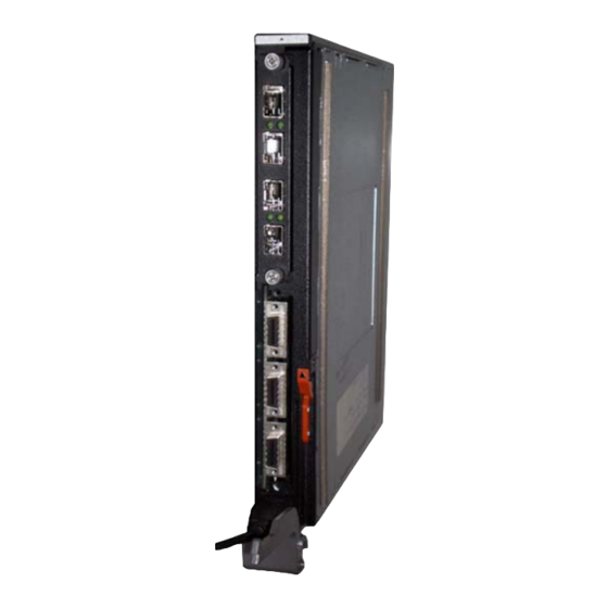
PowerConnect M8024-k Front Panel The PowerConnect M8024-k front panel includes four SFP+ ports an expansion slot for 10-Gigabit modules. The expansion slot can support SFP+, CX-4, or 10GBase-T modules. The SFP+ Module supports four ports, the CX-4 module supports three ports, and the 10GBase-T module supports two ports. -
Page 88: Console Redirect
CLI. Console Redirect The Dell M1000e Server Chassis includes a console redirect feature that allows you to manage each PCM6220, PCM6348, PCM8024, and PCM8024-k module from a single serial connection to the chassis. For more... -
Page 89: Led Definitions
LED Definitions This section describes the light emitting diodes (LEDs) on the front panel of the switch and on the optional modules that plug into the back panel. Port LEDs The integrated external 10/100/1000Base-T switch ports on the PowerConnect M6220 and M6348 switches include two LEDs. The integrated SFP+ switch ports on the PowerConnect M8024-k include one LED. - Page 90 SFP+ Port LEDs (PowerConnect M6348 and M8024-k) Each integrated SFP port on the PowerConnect M6348 switch includes two LEDs. Table 3-3 contains SFP port LED definitions for the PowerConnect M6348. Table 3-2. PowerConnect M6348 SFP+ Port LEDs Definitions Color/Activity Definition Green solid The port is linked.
-
Page 91: Module Leds
Module LEDs The 10GBase-T module has two or three LEDs per port, the SFP+ module has one LED per port, and the Stacking/10 GbE module does not have any LEDs. 10GBase-T Module LEDs Each 10GBase-T Module has three LEDs. Table 3-4 contains 10GBase-T port LED definitions for the PowerConnect M6220 and M8024. - Page 92 SFP+ Port LEDs Table 3-5 contains LED definitions for SFP+ port on the plug-in module available for PowerConnect M6220, M6348, M8024, and M8024-k switches. Table 3-5. SFP+ Port LEDs Definitions Color/Activity Definition LNK/ACT Green solid The port is linked. Green blinking The port is sending and/or receiving network traffic.
-
Page 93: System Leds
System LEDs The system LEDs for the PowerConnect M6220, M6348, M8024, and M8024-k switches are located on the right side of the front panel next to the console port. Figure 3-6. System LEDs System Status LED System Power LED Table 3-7 contains the status LED definitions for the PowerConnect M6220 and M6348 switches. - Page 94 Table 3-8 contains the status LED definitions for the PowerConnect M8024 and M8024-k switches. Table 3-8. PCM8024 and PCM8024-k Power and Status LED Definitions Color Definition Green Power is being supplied to the switch. The switch does not have power. Blue The switch is operating normally.
-
Page 95: Using Dell Openmanage Switch
Dell OpenManage Switch Administrator is a Web-based tool to help you manage and monitor a PowerConnect M6220/M6348/M8024/M8024-k switch. Table 4-1 lists the Web browsers that are compatible with Dell OpenManage Switch Administrator. The browsers have been tested on a PC running the Microsoft Windows operating system. -
Page 96: Starting The Application
Starting the Application To access the Dell OpenManage Switch Administrator and log on to the switch: 1 Open a web browser. 2 Enter the IP address of the switch in the address bar and press <Enter>. For information about assigning an IP address to a switch, see "Setting the IP Address and Other Basic Network Information"... -
Page 97: Understanding The Interface
5 The Dell OpenManage Switch Administrator home page displays. The home page is the Device Information page, which contains a graphical representation of the front panel of the switch. For more information about the home page, see "Device Information" on page 244. - Page 98 Save, Print, Refresh, Help Configuration and Status Options Command Button Using the Switch Administrator Buttons and Links Table 4-2 describes the buttons and links available from the Dell OpenManage Switch Administrator interface. Table 4-2. Button and Link Descriptions Button or Link Description...
-
Page 99: Defining Fields
Defining Fields User-defined fields can contain 1 159 characters, unless otherwise noted on – the Dell OpenManage Switch Administrator Web page. All characters may be used except for the following: • • •... -
Page 100: Understanding The Device View
Each port image is a hyperlink to the Port Configuration page for the specific port. Using Dell OpenManage Switch Administrator... -
Page 101: Using The Command-Line Interface
For more information about creating a serial connection, see the Getting Started Guide available at support.dell.com/manuals. 1 Connect the DB-9 connector of the supplied serial cable to a management station, and connect the USB type-A connector to the switch console port. -
Page 102: Telnet Connection
2 Start the terminal emulator, such as Microsoft HyperTerminal, and select the appropriate serial port (for example, COM 1) to connect to the console. 3 Configure the management station serial port with the following settings: • Data rate — 9600 baud. •... -
Page 103: Understanding Command Modes
Understanding Command Modes The CLI groups commands into modes according to the command function. Each of the command modes supports specific software commands. The commands in one mode are not available until you switch to that particular mode, with the exception of the User EXEC mode commands. You can execute the User EXEC mode commands in the Privileged EXEC mode. - Page 104 Table 5-1. Command Mode Overview Command Mode Access Method Command Prompt Exit or Access Previous Mode User EXEC The user is logout console> automatically in User EXEC mode unless the user is defined as a privileged user. Privileged EXEC From User Use the exit console# EXEC mode,...
-
Page 105: Entering Cli Commands
Entering CLI Commands The switch CLI uses several techniques to help you enter commands. Using the Question Mark to Get Help Enter a question mark (?) at the command prompt to display the commands available in the current mode. console(config-vlan)#? exit To exit from the mode. -
Page 106: Using Command Completion
You can also enter a question mark (?) after typing one or more characters of a word to list the available command or parameters that begin with the letters, as shown in the following example: console#show po? policy-map port ports Using Command Completion The CLI can complete partially entered commands when you press the <Tab>... -
Page 107: Understanding Error Messages
Understanding Error Messages If you enter a command and the system is unable to execute it, an error message appears. Table 5-2 describes the most common CLI error messages. Table 5-2. CLI Error Messages Message Text Description Indicates that you entered an incorrect or % Invalid input unavailable command. -
Page 108: Specifying Physical Ports
Table 5-3. History Buffer Navigation Keyword Source or Destination Up-arrow key Recalls commands in the history buffer, beginning with the most recent command. Repeats the key sequence to recall successively <Ctrl>+<P> older commands. Down-arrow key Returns to more recent commands in the history buffer after recalling commands with the up-arrow key. - Page 109 Unit, Slot, and Port Numbers The unit, slot, and port numbers are separated by forward slashes and follow the port type. For switches that do not support stacking (PCM8024 and PCM8024-k), the unit number is always 1. For stackable switches (PCM6220 and PCM6348), the unit number can be 1–12.
- Page 110 Using the Command-Line Interface...
-
Page 111: Default Settings
Default Settings This section describes the default settings for many of the software features on the PowerConnect M6220, M6348, M8024, and M8024-k switches. Table 6-1. Default Settings Feature Default IP address None Subnet mask None Default gateway None DHCP client Enabled on out-of-band (OOB) interface. - Page 112 Table 6-1. Default Settings (Continued) Feature Default SNMP logging Disabled Console logging Enabled (Severity level: debug and above) RAM logging Enabled (Severity level: debug and above) Persistent (FLASH) logging Disabled Enabled (No servers configured) SNMP Enabled (SNMPv1) SNMP Traps Enabled Auto Configuration Enabled Auto Save...
- Page 113 Table 6-1. Default Settings (Continued) Feature Default Protected Ports (Private VLAN Edge) None Flow Control Support (IEEE 802.3x) Enabled Head of Line Blocking Prevention Disabled Maximum Frame Size 1500 bytes Auto-MDI/MDIX Support Enabled Auto Negotiation Enabled Advertised Port Speed Maximum Capacity Broadcast Storm Control Disabled Port Mirroring...
- Page 114 Table 6-1. Default Settings (Continued) Feature Default STP Bridge Priority 32768 Multiple Spanning Tree Disabled Link Aggregation No LAGs configured LACP System Priority Routing Mode Disabled OSPF Admin Mode Enabled OSPF Router ID 0.0.0.0 IP Helper and UDP Relay Enabled Enabled VRRP Disabled...
-
Page 115: Setting The Ip Address And Other
Setting the IP Address and Other Basic Network Information This chapter describes how to configure basic network information for the switch, such as the IP address, subnet mask, and default gateway. The topics in this chapter include: • IP Address and Network Information Overview •... -
Page 116: Why Is Basic Network Information Needed
IP addresses. Default Domain Name Identifies your network, such as dell.com. If you enter a hostname and do not include the domain name information, the default domain name is automatically appended to the hostname. -
Page 117: How Is Basic Network Information Configured
You must use a console-port connection to perform the initial switch configuration. When you boot the switch for the first time and the configuration file is empty, the Dell Easy Setup Wizard starts. The Dell Easy Setup Wizard is a CLI-based tool to help you perform the initial switch configuration. - Page 118 Dell recommends that you use the OOB port for remote management. The following list highlights some advantages of using OOB management instead of in-band management: •...
-
Page 119: Default Network Information
Destination Unreachable, Fragmentation needed but DF set an ICMP notification, the switch will reduce the MSS. However, many firewalls block ICMP Destination Unreachable messages, which causes the destination to request the packet again until the connection times out. In order to resolve this issue, you can reduce the MSS setting to a more appropriate value on the local host or alternatively, you can set the MTU on the PowerConnect management port to a smaller value. -
Page 120: Configuring Basic Network Information (Web)
Configuring Basic Network Information (Web) This section provides information about the OpenManage Switch Administrator pages for configuring and monitoring basic network information on the PowerConnect M6220/M6348/M8024/M8024-k switch. For details about the fields on a page, click at the top of the page. Out-of-Band Interface Use the Out of Band Interface page to assign the Out of Band Interface IP address and subnet mask or to enable/disable the DHCP client for address... -
Page 121: Ip Interface Configuration (Default Vlan Ip Address)
IP Interface Configuration (Default VLAN IP Address) Use the IP Interface Configuration page to assign the Default VLAN IP address and Subnet Mask, the Default Gateway IP address, and to assign the boot protocol. To display the IP Interface Configuration page, click Routing → IP → IP Interface Configuration in the navigation panel. -
Page 122: Route Entry Configuration (Switch Default Gateway)
4 If you select Manual for the configuration method, specify the IP Address and Subnet Mask in the appropriate fields. 5 Click Apply. NOTE: You do not need to configure any additional fields on the page. For information about VLAN routing interfaces, see "Configuring Routing Interfaces" on page 855. - Page 123 Configuring a Default Gateway for the Switch: To configure the switch default gateway: 1 Open the Route Entry Configuration page. 2 From the Route Type field, select Default. Figure 7-4. Default Route Configuration (Default VLAN) 3 In the Next Hop IP Address field, enter the IP address of the default gateway.
-
Page 124: Domain Name Server
Domain Name Server Use the Domain Name Server page to configure the IP address of the DNS server. The switch uses the DNS server to translate hostnames into IP addresses. To display the Domain Name Server page, click System → IP Addressing → Domain Name Server in the navigation panel. -
Page 125: Default Domain Name
Default Domain Name Use the Default Domain Name page to configure the domain name the switch adds to a local (unqualified) hostname. To display the Default Domain Name page, click System → IP Addressing → Default Domain Name in the navigation panel. Figure 7-7. -
Page 126: Host Name Mapping
Host Name Mapping Use the Host Name Mapping page to assign an IP address to a static host name. The Host Name Mapping page provides one IP address per host. To display the Host Name Mapping page, click System → IP Addressing → Host Name Mapping. -
Page 127: Dynamic Host Name Mapping
The switch learns hosts dynamically by using the configured DNS server to resolve a hostname. For example, if you ping www.dell.com from the CLI, the switch uses the DNS server to lookup the IP address of dell.com and adds the entry to the Dynamic Host Name Mapping table. -
Page 128: Configuring Basic Network Information (Cli)
M6220/M6348/M8024/M8024-k switch. For more information about these PowerConnect M6220/M6348/M8024/M8024-k CLI commands, see the Reference Guide at support.dell.com/manuals. Enabling the DHCP Client on the OOB Port Beginning in Privileged EXEC mode, use the following commands to enable the DHCP client on the OOB port. -
Page 129: Managing Dhcp Leases
Managing DHCP Leases Beginning in Privileged EXEC mode, use the following commands to manage and troubleshoot DHCP leases on the switch. Command Purpose interface release dhcp Force the DHCPv4 client to release a leased address on the specified interface. interface renew dhcp Force the DHCP client to immediately renew an IPv4 address lease. -
Page 130: Configuring Static Network Information On The Oob Port
Configuring Static Network Information on the OOB Port Beginning in Privileged EXEC mode, use the following commands to configure a static IP address, subnet mask, and default gateway on the OOB port. Command Purpose configure Enter Global Configuration mode. interface out-of-band Enter Interface Configuration mode for the OOB port. -
Page 131: Configuring And Viewing Additional Network Information
Configuring and Viewing Additional Network Information Beginning in Privileged EXEC mode, use the following commands to configure a DNS server, the default domain name, and a static host name-to- address entry. Use the show commands to verify configured information and to view dynamic host name mappings. -
Page 132: Basic Network Information Configuration Example
Basic Network Information Configuration Example In this example, an administrator at a Dell office in California decides not to use the Dell Easy Setup Wizard to perform the initial switch configuration. The administrator configures a PowerConnect M6220/M6348/M8024/M8024-k switch to obtain its information from a DHCP server on the network and creates the administrative user with read/write access. - Page 133 Default Gateway....10.27.22.1 Protocol Current....DHCP Burned In MAC Address.... 001E.C9AA.AA08 5 View additional network information. console#show hosts Host name: Default domain: sunny.dell.com dell.com Name/address lookup is enabled Name servers (Preference order): 10.27.138.20, 10.27.138.21 Configured host name-to-address mapping: Host Addresses...
- Page 134 Setting Basic Network Information...
-
Page 135: Managing A Switch Stack
Managing a Switch Stack This chapter describes how to configure and manage a stack of switches. NOTE: Stacking is supported on the PowerConnect M6220 and PowerConnect M6348 switches. The PowerConnect M8024 and PowerConnect M8024-k switches do not support stacking. The topics covered in this chapter include: •... -
Page 136: Creating A Powerconnect M6220 Stack
The running configuration and application state is synchronized between the Master and Standby during the normal stacking operation. In a stack of three or more switches, Dell strongly recommends connecting the stack in a ring topology so that each switch is connected to two other switches. -
Page 137: Creating A Powerconnect M6348 Stack
Figure 8-1. Connecting a Stack of PowerConnect M6220 Switches M6220 Switches Stacking Cables The stack in Figure 8-1 has six M6220 switches connected through the stacking ports. The first stacking port on each switch is physically connected to the second stacking port on the next switch by using a stacking cable. The first stacking port on switch six is connected to the second stacking port on switch one. - Page 138 NOTE: The PowerConnect M6348 and M6220 can not be stacked together. 1 For each switch in the stack, connect one of the short stacking cables from stacking port one on the switch to stacking port two on the next switch. 2 If necessary, use a separately purchased, long (3 meter) stacking cable to connect the switches.
-
Page 139: Powerconnect 7000 Series And M6348 Stacking Compatibility
PowerConnect 7000 Series and M6348 Stacking Compatibility The stack can contain any combination of switch models in the PowerConnect 7000 Series as well as the PowerConnect M6348 switch, as long as all switches are running the same firmware version. For example, a single stack of six switches might include the following members: •... -
Page 140: Adding A Switch To The Stack
• If the Management Unit function is disabled, the unit remains a non- Management Unit. If the entire stack is powered OFF and ON again, the unit that was the Management Unit before the reboot will remain the Management Unit after the stack resumes operation. -
Page 141: Removing A Switch From The Stack
might trigger many other protocols. However, it is possible to intentionally pre-configure a unit. You can view the preconfigured/unassigned units by using the show switch CLI command. If a new switch is added to a stack of switches that are powered and running and already have an elected Management Unit, the newly added switch becomes a stack member rather than the Management Unit. -
Page 142: How Is The Firmware Updated On The Stack
How is the Firmware Updated on the Stack? When you add a new switch to a stack, the Stack Firmware Synchronization feature automatically synchronizes the firmware version with the version running on the stack master. The synchronization operation may result in either upgrade or downgrade of firmware on the mismatched stack member. - Page 143 management plane is application software running on the Management Unit that provides interfaces allowing a network administrator to configure the device. The Nonstop Forwarding (NSF) feature allows the forwarding plane of stack units to continue to forward packets while the control and management planes restart as a result of a power failure, hardware failure, or software fault on the stack Management Unit.
- Page 144 Checkpointing Switch applications (features) that build up a list of data such as neighbors or clients can significantly improve their restart behavior by remembering this data across a warm restart. This data can either be stored persistently, as DHCP server and DHCP snooping store their bindings database, or the Management Unit can checkpoint this data directly to the standby unit.
-
Page 145: Switch Stack Mac Addressing And Stack Design Considerations
Table 8-1. Applications that Checkpoint Data Application Checkpointed Data IGMP/MLD Snooping Multicast groups, list of router ports, last query data for each VLAN IPv6 NDP Neighbor cache entries iSCSI Connections LLDP List of interfaces with MED devices attached OSPFv2 Neighbors and designated routers OSPFv3 Neighbors and designated routers Route Table Manager... -
Page 146: Nsf Network Design Considerations
If you move the master unit of stack to a different place in the network, make sure you power down the whole stack before you redeploy the master unit so that the stack members do not continue to use the MAC address of the redeployed switch. -
Page 147: Default Stacking Values
Default Stacking Values Stacking is always enabled. NSF is enabled by default. You can disable NSF in order to redirect the CPU resources consumed by data checkpointing. Checkpointing only occurs when a backup unit is elected, so there is no need to disable the NSF feature on a standalone switch. -
Page 148: Managing And Monitoring The Stack (Web)
Managing and Monitoring the Stack (Web) This section provides information about the OpenManage Switch Administrator pages for configuring and monitoring stacking on a PowerConnect M6220 or PowerConnect M6348 switch. For details about the fields on a page, click at the top of the page. NOTE: The changes you make to the Stacking configuration pages take effect only after the device is reset. - Page 149 Changing the ID or Switch Type for a Stack Member To change the switch ID or type: 1 Open the Unit Configuration page. 2 Click Add to display the Add Unit page. Figure 8-4. Add Remote Log Server Settings 3 Specify the switch ID, and select the model number of the switch. 4 Click Apply.
-
Page 150: Stack Summary
Stack Summary Use the Stack Summary page to view a summary of switches participating in the stack. To display the Stack Summary page, click System → Stack Management → Stack Summary in the navigation panel. Figure 8-5. Stack Summary Managing a Switch Stack... -
Page 151: Stack Firmware Synchronization
Stack Firmware Synchronization Use the Stack Firmware Synchronization page to control whether the firmware image on a new stack member can be automatically upgraded or downgraded to match the firmware image of the stack master. To display the Stack Firmware Synchronization page, click System → Stack Management →... -
Page 152: Supported Switches
Supported Switches Use the Supported Switches page to view information regarding each type of supported switch for stacking, and information regarding the supported switches. To display the Supported Switches page, click System → Stack Management → Supported Switches in the navigation panel. Figure 8-7. -
Page 153: Stack Port Summary
Stack Port Summary Use the Stack Port Summary page to configure the stack-port mode and to view information about the stackable ports. This screen displays the unit, the stackable interface, the configured mode of the interface, the running mode as well as the link status and link speed of the stackable port. To display the Stack Port Summary page, click System →... -
Page 154: Stack Port Counters
Stack Port Counters Use the Stack Port Counters page to view the transmitted and received statistics, including data rate and error rate. To display the Stack Port Counters page, click System → Stack Management → Stack Point Counters in the navigation panel. Figure 8-9. -
Page 155: Nsf Summary
NSF Summary Use the NSF Summary page to change the administrative status of the NSF feature and to view NSF information. NOTE: The OSPF feature uses NSF to enable the hardware to continue forwarding IPv4 packets using OSPF routes while a backup unit takes over Management Unit responsibility. -
Page 156: Checkpoint Statistics
Checkpoint Statistics Use the Checkpoint Statistics page to view information about checkpoint messages generated by the master unit. To display the Checkpoint Statistics page, click System → Stack Management → Checkpoint Statistics in the navigation panel. Figure 8-11. Checkpoint Statistics Managing a Switch Stack... -
Page 157: Managing The Stack (Cli)
For more information PowerConnect M6220/M6348/M8024/M8024-k about these commands, see the CLI Reference Guide at support.dell.com/manuals. Configuring Stack Member and NSF Settings Beginning in Privileged EXEC mode, use the following commands to configure stacking and NSF settings. -
Page 158: Viewing And Clearing Stacking And Nsf Information
Command Purpose boot auto-copy-sw allow- Allow the firmware version on the newly added stack downgrade member to be downgraded if the firmware version on manager is older. exit Exit to Privileged EXEC mode. show auto-copy-sw View the Stack Firmware Synchronization settings for the stack. -
Page 159: Stacking And Nsf Usage Scenarios
Command Purpose show checkpoint View information about checkpoint messages generated by statistics the master unit. clear checkpoint Reset the checkpoint statistics counters to zero. statistics Stacking and NSF Usage Scenarios Only a few settings are available to control the stacking configuration, such as the designation of the standby unit or enabling/disabling NSF. -
Page 160: Basic Failover
Basic Failover In this example, the stack has four members that are connected through a daisy-chain, as Figure 8-12 shows. Figure 8-12. Basic Stack Failover When all four units are up and running, the show switch CLI command gives the following output: console#show switch Management Standby... - Page 161 At this point, if Unit 2 is powered off or rebooted due to an unexpected failure, show switch gives the following output: console#show switch Management Standby Preconfig Plugged- Switch Code Status Status Model ID in Model Status Version --- --------- ------- -------- ------------------- --------...
-
Page 162: Preconfiguring A Stack Member
Preconfiguring a Stack Member To preconfigure a stack member before connecting the physical unit to the stack, use the show support switchtype command to obtain the SID of the unit to be added. The example in this section demonstrates pre-configuring a PowerConnect 7048P switch on a stand-alone PowerConnect 7048R switch. - Page 163 3 Confirm the stack configuration. Some of the fields have been omitted from the following output due to space limitations. console#show switch SW Management Standby Preconfig Plugged-in Switch Code Status Status Model ID Model ID Status Version --- --------- ------- -------- --------- ---------- -------- Mgmt Sw PCT7048R PCT7048R...
-
Page 164: Nsf In The Data Center
NSF in the Data Center Figure 8-13 illustrates a data center scenario, where the stack of two PowerConnect switches acts as an access switch. The access switch is connected to two aggregation switches, AS1 and AS2. The stack has a link from two different units to each aggregation switch, with each pair of links grouped together in a LAG. -
Page 165: Nsf And Voip
NSF and VoIP Figure 8-14 shows how NSF maintains existing voice calls during a Management Unit failure. Assume the top unit is the Management Unit. When the Management Unit fails, the call from phone A is immediately disconnected. The call from phone B continues. On the uplink, the forwarding plane removes the failed LAG member and continues using the remaining LAG member. -
Page 166: Nsf And Dhcp Snooping
NSF and DHCP Snooping Figure 8-15 illustrates an L2 access switch running DHCP snooping. DHCP trusted snooping only accepts DHCP server messages on ports configured as ports. DHCP snooping listens to DHCP messages to build a bindings database that lists the IP address the DHCP server has assigned to each host. IP Source Guard (IPSG) uses the bindings database to filter data traffic in hardware based on source IP address and source MAC address. -
Page 167: Nsf And The Storage Access Network
If a host is in the middle of an exchange with the DHCP server when the failover occurs, the exchange is interrupted while the control plane restarts. When DHCP snooping is enabled, the hardware traps all DHCP packets to the CPU. The control plane drops these packets during the restart. The DHCP client and server retransmit their DHCP messages until the control plane has resumed operation and messages get through. - Page 168 Figure 8-16. NSF and a Storage Area Network Disc Array (iSCSI Targets) Servers (iSCSI Initiators) 10.1.1.2 10.1.1.3 10.1.1.1 10.1.1.10 10.1.1.11 When the Management Unit fails, session A drops. The initiator at 10.1.1.10 detects a link down on its primary NIC and attempts to reestablish the session on its backup NIC to a different IP address on the disk array.
-
Page 169: Nsf And Routed Access
NSF and Routed Access Figure 8-17 shows a stack of three units serving as an access router for a set of hosts. Two LAGs connect the stack to two aggregation routers. Each LAG is a member of a VLAN routing interface. The stack has OSPF and PIM adjacencies with each of the aggregation routers. - Page 170 JOIN messages upstream. The control plane updates the driver with checkpointed unicast routes. The forwarding plane reconciles L3 hardware tables. The OSPF graceful restart finishes, and the control plane deletes any stale unicast routes not relearned at this point. The forwarding plane reconciles L3 multicast hardware tables.
-
Page 171: Controlling Management Access
Controlling Management Access This chapter describes how to control access to the switch management interface through switch-based authentication or by using TACACS+ or RADIUS servers. It also includes information about controlling access through Telnet, SSH, HTTP, and HTTPs. The Denial of Service (DoS) protection feature is also described in this chapter. - Page 172 Table 9-1. Management Security Features Management Security Description Feature Management Access Contains rules to apply to one or more in-band ports, LAGs, Control List (ACL) or VLANs to limit management access by method (for example, Telnet or HTTP) and/or source IP address. NOTE: Management ACLs cannot be applied to the OOB port.
-
Page 173: What Are The Recommendations For Management Security
What Are the Recommendations for Management Security? Selecting the authentication policy for a network is very important. In large deployments, many administrators prefer to use a RADIUS or TACACS+ server because it allows the authentication policy to be applied system wide with little administrative effort. -
Page 174: How Does Tacacs+ Control Management Access
• Console—Authenticates access through the console port (CLI only). • Telnet—Authenticates users accessing the CLI by using a Telnet or SSH client. • Secure HTTP—Authenticates users accessing OpenManage Switch Administrator by using an HTTPS connection. • HTTP—Authenticates users accessing OpenManage Switch Administrator by using an HTTP connection. - Page 175 Figure 9-1. Basic TACACS+ Topology Backup TACACS+ Server PowerConnect Switch Primary TACACS+ Server Management Network Management Host You can configure the TACACS+ server list with one or more hosts defined via their network IP address. You can also assign each a priority to determine the order in which the TACACS+ client will contact them.
-
Page 176: How Does Radius Control Management Access
How Does RADIUS Control Management Access? Many networks use a RADIUS server to maintain a centralized user database that contains per-user authentication information. RADIUS servers provide a centralized authentication method for: • Telnet Access • Web Access • Console to Switch Access •... - Page 177 Figure 9-2. RADIUS Topology Backup RADIUS Server PowerConnect Switch Primary RADIUS Server Management Network Management Host The server can authenticate the user itself or make use of a back-end device to ascertain authenticity. In either case a response may or may not be forthcoming to the client.
-
Page 178: What Are Radius Server Groups
enable Auth-Type := Local, User-Password == "pass5678" Service-Type = Administrative-User The values for the Service-Type attribute are as follows: • NAS-Prompt-User indicates the user should be provided a command prompt on the switch, which is acting as the Network Access Server (NAS), from which nonprivileged commands can be executed. - Page 179 When multiple RADIUS servers are configured with different names, the servers are in different groups. The primary/secondary designation and priority applies to RADIUS servers only within the same group. Within a named group, the switch always attempts to contact the primary RADIUS server first.
-
Page 180: What Other Features Use Authentication
What Other Features Use Authentication? In addition to controlling access to the management interface, the switch can use RADIUS, IAS, or the local user database to provide port-based access control. Port-based access control specifies whether devices that are connected to the switch ports are allowed access to the network. The IEEE 802.1X feature (also known as Dot1X) and Captive Portal feature use RADIUS or the local user database to control network access. - Page 181 Table 9-2. Management Security Default Values (Continued) Management Security Default Feature Authentication The following three Authentication Profiles are configured Profiles by default: • defaultList—Method is NONE, which means no authentication is required. • networkList—Method is LOCAL, which means the user credentials are verified against the information in the local user database.
-
Page 182: Controlling Management Access (Web)
Controlling Management Access (Web) This section provides information about the OpenManage Switch Administrator pages for configuring and monitoring management security on a PowerConnect M6220/M6348/M8024/M8024-k switch. For details about the fields on a page, click at the top of the page. Access Profile Use the Access Profile page to define a profile and rules for accessing the switch. - Page 183 Adding and Configuring an Access Profile To configure an access profile: 1 Open the Access Profile page. 2 Click Add Profile to display the Add an Access Profile page. 3 Enter a name for the Access Profile. 4 Specify a rule for management access, and then click Apply. In Figure 9-4, the Access Profile name is mgmt_ACL, and access is permitted on VLAN 1 from any host in the 10.27.65.0/24 subnet.
- Page 184 Figure 9-5 shows the configuration of an additional rule that allows management access to a host in the 10.27.65.0/24 subnet that is connected to Port 1. The rule priority is 2. This rule might be necessary if Port 1 is not a member of VLAN 1.
- Page 185 Figure 9-6. View Access Profile Information 8 Click Access Profile to return to the main page for the feature. 9 To activate the profile, select the Set Active Access Profile option, and then click Apply. NOTE: The switch enforces the profile rules only if the profile is active. If an access profile is not activated, the device can be accessed by any host and on any interface.
-
Page 186: Authentication Profiles
Figure 9-7. Activate the Access Profile Authentication Profiles User authentication occurs locally and on an external server. Use the Authentication Profiles page to select the user authentication methods for the defaultList and networkList. These Authentication Profiles are created by default. To display the Authentication Profiles page, click System →... - Page 187 Figure 9-8. Authentication Profiles Adding and Configuring an Authentication Profile To configure an authentication profile: 1 Open the Authentication Profiles page. 2 Click Add to display the Add Authentication Profiles page. 3 Enter a name for the Authentication Profile. 4 Select the authentication methods to use for the profile. The order in which you select the methods is the order the switch will use to attempt to authentication the user.
- Page 188 Figure 9-9. Configure Authentication Profile 5 Click Apply. A profile is created. You can apply the newly created authentication profile to an access method by using the System → Management Security → Select Authentication page. For example, you can select myList as the login authentication for anyone who connects to the switch by using Telnet.
- Page 189 6 To view the existing Authentication Profiles and the order in which the login methods are used, click Show All. Figure 9-10. View Authentication Profile Table Controlling Management Access...
-
Page 190: Select Authentication
Select Authentication After authentication profiles are defined, you can apply them to management access methods. For example, console users can be authenticated by Authentication Profile List 1, while Telnet users are authenticated by Authentication Profile List 2. To display the Select Authentication page, click System → Management Security →... -
Page 191: Password Management
Password Management Password management provides increased network security and improved password control. Passwords for SSH, Telnet, HTTP , HTTPS, and SNMP access are assigned security features, including: • Defining minimum password lengths (the minimum password length is 8 when password length-checking is enabled) •... - Page 192 Figure 9-12. Password Management Adding Excluded Keywords To prevent keywords from being used in passwords: 1 Make sure Create is selected from the Password Exclude-keyword menu. 2 Specify the keyword to exclude. 3 Click Add Excluded Keyword. Controlling Management Access...
-
Page 193: Last Password Set Result
Last Password Set Result Use the Last Password Set Result page to view information about the most recently configured password for a user in the Local User Database. To display the Last Password Set Result page, click System → Management Security →... -
Page 194: User Login Configuration
User Login Configuration Use the User Login Configuration page to select the list to use to authenticate attempts to login to the switch by users configured in the Local User Database. Each user in the database can have a different list applied. To display the User Login Configuration page, click System →... -
Page 195: Local User Database
Local User Database Use the Local User Database page to define passwords, access rights for users and reactivate users whose accounts have been suspended. This page also contains fields to allow you to configure SNMPv3 settings for users in the local database. - Page 196 Adding a User to the Local Database To add local users: 1 Open the Local User Database page. 2 Click Add to display the Add a New User page. 3 Specify a login name, select the access level, and type/retype the password. Figure 9-16.
-
Page 197: Line Password
Line Password Use the Line Password page to define passwords that are used to access the CLI through the Console port, SSH, or Telnet. To display the Line Password page, click System → Management Security → Line Password in the navigation panel. Figure 9-17. -
Page 198: Tacacs+ Settings
TACACS+ Settings TACACS+ provides centralized security for validation of users accessing the switch, while still retaining consistency with RADIUS and other authentication processes. TACACS+ provides the following services: • Authentication — Provides authentication during login and through user names and user-defined passwords. •... - Page 199 Adding TACACS+ Host Information To add a TACACS+ host: 1 Open the TACACS+ Settings page. 2 Click Add to display the Add a TACACS+ Host page. 3 Specify a the hostname or IP address of the TACACS+ the switch will use to authenticate users.
-
Page 200: Radius Global Configuration
Figure 9-21. View Local User Database Entries RADIUS Global Configuration Use the RADIUS Global Configuration page to configure that affect all RADIUS servers that are configured on the switch. To display the RADIUS Global Configuration page, click System → Management Security → RADIUS Global Configuration in the navigation panel. -
Page 201: Radius Server Configuration
RADIUS Server Configuration From the RADIUS Server Configuration page, you can add a new RADIUS server, configure settings for a new or existing RADIUS server, and view RADIUS server status information. The RADIUS client on the switch supports up to 32 named authentication and accounting servers. To access the RADIUS Server Configuration page, click System →... - Page 202 4 Use the default RADIUS server name or enter up to 32 alphanumeric characters. Spaces, hyphens, and underscores are also permitted. You can use the same name for multiple RADIUS Authentication servers. RADIUS clients can use RADIUS servers with the same name as backups for each other.
-
Page 203: Radius Accounting Server Configuration
Figure 9-25. Viewing the RADIUS Server Table RADIUS Accounting Server Configuration From the RADIUS Accounting Server Configuration page, you can add a new RADIUS accounting server, configure settings for a new or existing RADIUS accounting server, and view RADIUS accounting server status information. - Page 204 Adding and Configuring RADIUS Accounting Server Information To add a RADIUS accounting server: 1 Open the RADIUS Accounting Server Configuration page. 2 Click Add to display the Add RADIUS Accounting Server page. 3 Specify the IP address of the RADIUS accounting server. 4 Use the default RADIUS server name or enter up to 32 alphanumeric characters.
-
Page 205: Radius Accounting Server Statistics
Figure 9-28. Viewing the RADIUS Accounting Server Table RADIUS Accounting Server Statistics Use the RADIUS Accounting Server Statistics page to view statistical information for each RADIUS accounting server configured on the system. To access the RADIUS Accounting Server Statistics page, click System → Management Security →... -
Page 206: Radius Server Statistics
RADIUS Server Statistics Use the RADIUS Server Statistics page to view statistical information for each RADIUS server configured on the system. To access the RADIUS Server Statistics page, click System → Management Security → RADIUS Server Statistics in the navigation panel. Figure 9-30. -
Page 207: Authorization Network Radius
Authorization Network RADIUS In some networks, the RADIUS server is responsible for assigning traffic to a particular VLAN. From the Authorization Network RADIUS page, you can enable the switch to accept VLAN assignment by the RADIUS server. For more information about VLANs and RADIUS-assigned VLANs, see "Dynamic VLAN Creation"... -
Page 208: Telnet Server
Telnet Server Use the Telnet Server page to enable or disable telnet service on the switch or to modify the telnet port. To display the Telnet Server page, click System → Management Security → Telnet Server. Figure 9-32. Telnet Server Controlling Management Access... -
Page 209: Denial Of Service
Denial of Service Denial of Service (DoS) refers to the exploitation of a variety of vulnerabilities which would interrupt the service of a host or make a network unstable. Use the Denial of Service page to configure settings to help prevent DoS attacks. -
Page 210: Secure Http Configuration
Secure HTTP Configuration Secure HTTP (HTTPS) increases the security of web-based management by encrypting communication between the administrative system and the switch. Use the Secure HTTP page to manage the HTTPS mode and certificate information that enables management of the switch through HTTPS. To display the Secure HTTP page, click System →... - Page 211 Importing and Requesting Certificates Use the following steps to import or request a certificate by using SSH. 1 From the Secure HTTP page, click SSH Request. Figure 9-35. Secure HTTP - SSH Request 2 Select the certificate number. 3 Complete the fields that are relevant to the certificate. 4 To import the certificate, click Certificate Import.
- Page 212 Viewing Certificate Information To view the certificate request or to view the generated certificate, click Show All. Figure 9-36. View Certificate Requests Controlling Management Access...
-
Page 213: Secure Shell Configuration
Secure Shell Configuration Secure Shell (SSH) is similar to Telnet but increases the security of CLI- based management by creating a secure channel for communication between the administrative system and the switch. Use the Secure Shell page to manage the SSH mode and other information that enables management of the switch through SSH. -
Page 214: Secure Public Key Configuration
Generate RSA Keys — Begin generating RSA host keys. Note that to • generate SSH key files, SSH must be administratively disabled and there must be no active SSH sessions. Generate DSA Key — Begin generating DSA host keys. Note that to •... - Page 215 Configuring a Public Key Use the following steps to configure a public key for SSH. 1 From the Secure Public Key page, click Add. Figure 9-39. Secure Public Key — Add 2 Specify the algorithm to use of the public-key cryptography, either DSA or RSA.
-
Page 216: Controlling Management Access (Cli)
For more information about PowerConnect M6220/M6348/M8024/M8024-k CLI these commands, see the Reference Guide at support.dell.com/manuals. Configuring a Management Access List NOTE: Management ACLs can be applied only to in-band ports and cannot be applied to the OOB port. - Page 217 Command Purpose permit ip-source Allow access to the management interface from hosts that address mask [mask meet the specified IP address value and other optional prefix-length interface- criteria. type interface-number interface-type interface-number • — A valid port, LAG, or service [service ] [priority VLAN interface, for example gi1/0/13, port-channel 3, or...
-
Page 218: Adding Users To The Local Database
Adding Users to the Local Database Beginning in Privileged EXEC mode, use the following commands to add users to the local user database. Command Purpose configure Enter Global Configuration mode. name username Add a new user to the local users database. password password [level... -
Page 219: Configuring And Applying Authentication Profiles
Configuring and Applying Authentication Profiles Beginning in Privileged EXEC mode, use the following commands to create an authentication list, configure the authentication methods for that list, and apply the list to an access method. Command Purpose configure Enter Global Configuration mode. aaa authentication login Configure the methods used to authenticate a user list-name... -
Page 220: Managing Passwords
Command Purpose line {console|ssh Enter Line configuration mode for the specified access |telnet} method. login authentication Specify the login authentication list to use for the line list-name {default| access. The list is applied to the current line mode (console, Telnet, or SSH). enable authentication Specify the enable authentication list to use for access to list-name... - Page 221 Command Purpose passwords lock-out Specify the number of times a user can enter an incorrect attempts password before being denied access to the management interface. NOTE: Password lockout applies only to local users. Users authenticated by RADIUS and TACACS+ are subject to the policies defined by the RADIUS or TACACS+ server.
-
Page 222: Configuring Radius Server Information
Command Purpose passwords strength Specify up to three keywords to exclude in a password. The word exclude-keyword password does not accept the keyword in any form (in between the string, case in-sensitive and reverse) as a substring. passwords strength- Verify the strength of a password during configuration. check exit Exit to Privileged EXEC mode. - Page 223 Command Purpose key-string key [ Set the authentication and encryption key for all RADIUS communications between the switch and the RADIUS server. NOTE: You can also use the radius-server key [ key-string command in Global Configuration mode to set the same authentication and encryption key for all configured RADIUS servers.
-
Page 224: Configuring Tacacs+ Server Information
Command Purpose show radius statistics View the RADIUS statistics for the switch. You can specify [[accounting | additional information to narrow the scope of the authentication] command output. ipaddress hostname • accounting | authentication — The type of server servername name (accounting or authentication). -
Page 225: Configuring Telnet And Ssh Access
Configuring Telnet and SSH Access Beginning in Privileged EXEC mode, use the following commands to specify Telnet and SSH server settings on the switch. Command Purpose configure Enter Global Configuration mode. ip telnet server disable Disable the Telnet service on the switch ip ssh server Allow access to the switch management interface by using SSH, which is disabled by default. -
Page 226: Configuring Http And Https Access
Command Purpose show crypto key pubkey- View SSH public keys stored on the switch. chain ssh [username username • — Specifies the remote SSH client username. username ] [fingerprint (Range: 1–48 characters) bubble-babble|hex] • bubble-babble — Fingerprints in Bubble Babble format. •... - Page 227 Command Purpose <CTRL + Z> Exit to Privileged EXEC mode. crypto certificate Generate and display a certificate request for HTTPS. This number request command takes you to Crypto Certificate Request mode. In this mode, you can use the following commands to specify certificate details: •...
-
Page 228: Configuring Dos Information
Command Purpose show crypto certificate View the SSL certificates of your switch. mycertificate show ip http server Display the HTTPS server configuration. secure status show ip http server Display the HTTP server configuration. status Configuring DoS Information Beginning in Privileged EXEC mode, use the following commands to specify settings to help prevent DoS attacks on the switch. - Page 229 Command Purpose size dos-control icmp [ Enable Maximum ICMP Packet Size Denial of Service size protections, where is the Maximum ICMP packet size. (Range: 0-16376). If ICMP Echo Request (PING) packets ingress having a size greater than the configured value, the packets are dropped.
-
Page 230: Management Access Configuration Examples
Management Access Configuration Examples This section contains the following examples: • Configuring a Management Access List • Configuring an Authentication Profile • Configuring the Primary and Secondary RADIUS Servers • Configuring Password Lockout Configuring a Management Access List The commands in this example create a management ACL that permits access to the switch through the in-band switch ports on VLAN 1 and on port 9 from hosts with an IP address in the 10.27.65.0 subnet. -
Page 231: Configuring The Primary And Secondary Radius Servers
The commands in this example configure primary and secondary RADIUS servers that the switch will use to authenticate access. The RADIUS servers belong to the same named server group (Dell-RADIUS) and use the same RADIUS secret (test1234). A third RADIUS server is configured as an accounting server, and RADIUS accounting is globally enabled. - Page 232 2 Configure the secondary RADIUS server. console(config)#radius-server host auth 10.27.65.104 console(Config-auth-radius)#name Dell-RADIUS console(Config-auth-radius)#key test1234 console(Config-auth-radius)#exit 3 Configure the RADIUS accounting server. console(config)#radius-server host acct 10.27.65.114 console(Config-acct-radius)#key test1234 console(Config-acct-radius)#name Dell-RADIUS- Accounting console(Config-acct-radius)#exit 4 Activate RADIUS accounting. console(config)#aaa accounting network default start-stop group radius console(config)#exit 5 View the configured RADIUS servers.
-
Page 233: Configuring An Authentication Profile
Configuring an Authentication Profile The commands in this example create a new authenticating profile that uses the RADIUS server configured in the previous example to authenticate users who attempt to access the switch management interface by using SSH or Telnet. If the RADIUS authentication is unsuccessful, the switch uses the local user database to attempt to authenticate the users. -
Page 234: Configuring Password Lockout
4 View the current authentication methods and profiles. console#show authentication methods Login Authentication Method Lists --------------------------------- defaultList none networkList local myList radius local Enable Authentication Method Lists ---------------------------------- enableList none Line Login Method List Enable Method List ------- ----------------- ------------------ Console defaultList enableList... - Page 235 The password lockout feature disables local access to the switch for a given user name if the user fails to supply the correct password within the configured number of attempts. Failed attempts to log on do not need to close together in time; consecutive login failures separated by extensive time periods can still cause a user to be locked out.
- Page 236 4 View information about the authentication profiles. By default, Console (serial) access uses the defaultList authentication. The defaultList does not require authentication, but the networkList requires authentication by verifying the user name and password against an entry in the local database.
- Page 237 The following screen text shows an example session that results in the lockout of local user abc User:abc Password:******** ! Enter invalid password User:abc Password:******** ! Enter invalid password User:abc Password:******** User: <188> FEB 04 19:44:52 10.27.22.46-1 USER_MGR[183162896]: user_mgr.c(1640) 695 %% User abc locked out on authentication failure ! Enter valid password User:abc...
- Page 238 Controlling Management Access...
-
Page 239: Monitoring And Logging System
Monitoring and Logging System Information This chapter provides information about the features you use to monitor the switch, including logging, cable tests, and email alerting. The topics covered in this chapter include: • System Monitoring Overview • Default Log Settings •... -
Page 240: Why Is System Information Needed
Why Is System Information Needed? The information the switch provides can help you troubleshoot issues that might be affecting system performance. The cable diagnostics test help you troubleshoot problems with the physical connections to the switch. Auditing access to the switch and the activities an administrator performed while managing the switch can help provide security and accountability. -
Page 241: What Are The Severity Levels
What Are the Severity Levels? For each local or remote log file, you can specify the severity of the messages to log. Each severity level is identified by a name and a number. Table 10-1 provides information about the severity levels. Table 10-1. -
Page 242: What Is The Log Message Format
The first part of the log message up to the first left bracket is fixed by the Syslog standard (RFC 3164). The second part up to the two percent signs is standardized for all Dell PowerConnect logs. The variable text of the log message follows. The log message is limited to 96 bytes. -
Page 243: What Factors Should Be Considered When Configuring Logging
Message — Contains the text of the log message. What Factors Should Be Considered When Configuring Logging? Dell recommends that network administrators deploy a syslog server in their network and configure all switches to log messages to the syslog server. -
Page 244: Monitoring System Information And Configuring Logging (Web)
Device Information The Device Information page displays after you successfully log on to the switch by using the Dell OpenManage Switch Administrator. This page is a virtual representation of the switch front panel. Use the Device Information page to view information about the port status, system status, and the switch stack. - Page 245 Figure 10-2. Stack View For more information about the device view features, see "Understanding the Device View" on page 100. Monitoring and Logging System Information...
-
Page 246: System Health
System Health Use the Health page to view status information about the switch power and ventilation sources. To display the Health page, click System → General → Health in the navigation panel. Figure 10-3. Health Monitoring and Logging System Information... -
Page 247: System Resources
System Resources Use the System Resources page to view information about memory usage and task utilization. To display the System Resources page, click System → General → System Resources in the navigation panel. Figure 10-4. System Resources Monitoring and Logging System Information... -
Page 248: Integrated Cable Test For Copper Cables
Integrated Cable Test for Copper Cables Use the Integrated Cable Test for Copper Cables page to perform tests on copper cables. Cable testing provides information about where errors occurred in the cable, the last time a cable test was performed, and the type of cable error which occurred. -
Page 249: Optical Transceiver Diagnostics
To view a summary of all integrated cable tests performed, click the Show All link. Figure 10-6. Integrated Cable Test Summary Optical Transceiver Diagnostics Use the Optical Transceiver Diagnostics page to perform tests on Fiber Optic cables. To display the Optical Transceiver Diagnostics page, click System → Diagnostics →... - Page 250 Figure 10-7. Optical Transceiver Diagnostics To view a summary of all optical transceiver diagnostics tests performed, click the Show All link. Figure 10-8. Optical Transceiver Diagnostics Summary Monitoring and Logging System Information...
-
Page 251: Log Global Settings
Log Global Settings Use the Global Settings page to enable logging globally, to enable other types of logging. You can also specify the severity of messages that are logged to the console, RAM log, and flash-based log file. The Severity table lists log messages from the highest severity (Emergency) to the lowest (Debug). -
Page 252: Ram Log
RAM Log Use the RAM Log page to view information about specific RAM (cache) log entries, including the time the log was entered, the log severity, and a description of the log. To display the RAM Log, click System → Logs → RAM Log in the navigation panel. -
Page 253: Log File
Log File The Log File contains information about specific log entries, including the time the log was entered, the log severity, and a description of the log. To display the Log File, click System → Logs → Log File in the navigation panel. - Page 254 Figure 10-12. Remote Log Server Adding a New Remote Log Server To add a log server: 1 Open the Remote Log Server page. 2 Click Add to display the Add Remote Log Server page. 3 Specify the IP address or hostname of the remote server. 4 Define the UDP Port and Description fields.
- Page 255 Figure 10-13. Add Remote Log Server 5 Select the severity of the messages to send to the remote server. NOTE: When you select a severity level, all higher severity levels are automatically selected. 6 Click Apply. Click the Show All link to view or remove remote log servers configured on the system.
-
Page 256: Email Alert Global Configuration
Figure 10-14. Show All Log Servers Email Alert Global Configuration Use the Email Alert Global Configuration page to enable the email alerting feature and configure global settings so that system log messages can be sent to from the switch to one or more email accounts. To display the Email Alert Global Configuration page, click System →... -
Page 257: Email Alert Mail Server Configuration
Email Alert Mail Server Configuration Use the Email Alert Mail Server Configuration page to configure information about the mail server the switch uses for sending email alert messages. To display the Email Alert Mail Server Configuration page, click System → Email Alerts →... - Page 258 Figure 10-17. Add Mail Server 4 Click Apply. 5 If desired, click Configuration to return to the Email Alert Mail Server Configuration page to specify port and security settings for the mail server. Click the Show All link to view or remove mail servers configured on the switch.
-
Page 259: Email Alert Subject Configuration
Email Alert Subject Configuration Use the Email Alert Subject Configuration page to configure the subject line for email alerts that are sent by the switch. You can customize the subject for the message severity and entry status. To display the Email Alert Subject Configuration page, click System → Email Alerts →... -
Page 260: Email Alert To Address Configuration
Email Alert To Address Configuration Use the Email Alert To Address Configuration page to specify where the email alerts are sent. You can configure multiple recipients and associate different message severity levels with different recipient addresses. To display the Email Alert To Address Configuration page, click System → Email Alerts →... -
Page 261: Email Alert Statistics
Figure 10-22. View Email Alert To Address Configuration Email Alert Statistics Use the Email Alert Statistics page to view the number of emails that were successfully and unsuccessfully sent, and when emails were sent. To display the Email Alert Statistics page, click System → Email Alerts → Email Alert Statistics in the navigation panel. -
Page 262: Monitoring System Information And Configuring Logging (Cli)
PowerConnect M6220/M6348/M8024/M8024-k switch. For more information about these PowerConnect M6220/M6348/M8024/M8024-k CLI commands, see the Reference Guide at support.dell.com/manuals. Viewing System Information Beginning in Privileged EXEC mode, use the following commands to view system health and resource information. Command... -
Page 263: Configuring Local Logging
Command Purpose test copper-port tdr Perform the Time Domain Reflectometry (TDR) test to interface diagnose the quality and characteristics of a copper cable attached to the specified port. CAUTION: Issuing the test copper-port tdr command will bring the interface down. The interface is specified in unit/slot/port format. - Page 264 Command Purpose logging Enable logging to the specified file. Optionally, you can {buffered|console| file} define a logging discriminator to help filter log messages severity and set the severity of the messages to log. • buffered — Enables logging to the RAM file (cache). If the switch resets, the buffered logs are cleared.
-
Page 265: Configuring Remote Logging
Configuring Remote Logging Beginning in Privileged EXEC mode, use the following commands to define a remote server to which the switch sends log messages. Command Purpose configure Enter Global Configuration mode. ip-address logging { Define a remote log server and enter the configuration hostname mode for the specified log server. -
Page 266: Configuring Mail Server Settings
Configuring Mail Server Settings Beginning in Privileged EXEC mode, use the following commands to configure information about the mail server (SMTP host) on the network that will initially receive the email alerts from the switch and relay them to the correct recipient. Command Purpose configure... -
Page 267: Configuring Email Alerts For Log Messages
Configuring Email Alerts for Log Messages Beginning in Privileged EXEC mode, use the following commands to configure email alerts so that log messages are sent to the specified address. Command Purpose configure Enter Global Configuration mode. severity logging email [ ] Enable email alerting and determine which non-critical log severity messages should be emailed. - Page 268 Command Purpose logging email test Send a test email to the configured recipient to verify that message-type {urgent | the feature is properly configured. non-urgent | both} body message-body CTRL + Z Exit to Privileged EXEC mode. show logging email View the configured settings for email alerts.
-
Page 269: Logging Configuration Examples
Logging Configuration Examples This section contains the following examples: • Configuring Local and Remote Logging • Configuring Email Alerting Configuring Local and Remote Logging This example shows how to enable switch auditing and CLI command logging. Log messages with a severity level of Notification (level 5) and above are sent to the RAM (buffered) log. - Page 270 4 Verify the remote log server configuration. console#show syslog-servers IP Address/Hostname Port Severity Description ------------------------- ------ -------------- ---------- 192.168.2.10 debugging Syslog Server 5 Verify the local logging configuration and view the log messages stored in the buffer (RAM log). console#show logging Logging is enabled Console Logging: level debugging.
-
Page 271: Configuring Email Alerting
Configuring Email Alerting The commands in this example define the SMTP server to use for sending email alerts. The mail server does not require authentication and uses the standard TCP port for SMTP, port 25, which are the default values. Only Emergency messages (severity level 0) will be sent immediately as individual emails, and messages with a severity of alert, critical, and error (levels 1-3) will be sent in a single email every 120 minutes. - Page 272 5 Specify the address where email alerts should be sent. console(config)#logging email message-type both to-addr administrator@dell.com 6 Specify the text that will appear in the email alert Subject line. console(config)#logging email message-type urgent subject "LOG MESSAGES - EMERGENCY"...
- Page 273 Email Alert Non Urgent Severity Level..3 Email Alert Trap Severity Level....6 Email Alert Notification Period....120 min Email Alert To Address Table: For Msg Type......1 Address1......administrator@dell.com For Msg Type......2 Address1......administrator@dell.com Email Alert Subject Table For Msg Type 1, subject is....LOG MESSAGES - EMERGENCY For Msg Type 2, subject is....LOG MESSAGE...
- Page 274 Monitoring and Logging System Information...
-
Page 275: Managing General System Settings
Managing General System Settings This chapter describes how to set system information, such as the hostname, and time settings, and how to select the Switch Database Management (SDM) template to use on the switch. This chapter also describes how to view expansion slot information as well as how to configure the operational mode and Port Aggregator feature. -
Page 276: Why Does System Information Need To Be Configured
Table 11-1. System Information Feature Description SDM Template Determines the maximum resources a switch or router can use for various features. For more information, see "What Are SDM Templates?" on page 280 The switch can obtain the time from a Simple Network Time Protocol (SNTP) server, or you can set the time manually. -
Page 277: What Is Simple Mode
The Banner can provide information about the switch status. For example, if multiple users connect to the switch, the message of the day (MOTD) banner might alert everyone who connects to the switch about a scheduled switch image upgrade. What is Simple Mode? The PowerConnect M6220, M6348, M8024, and M8024-k switches support a simple operational mode to allow auto configuration of complex network setting. - Page 278 • Simple mode allows the user to create Aggregation Groups where internal ports and external ports can be configured in a separate broadcast domain. • Security-related configurations: dot1x, RADIUS, TACACS+ are allowed when the switch is operating in Simple Mode. •...
-
Page 279: What Is The Port Aggregator Feature
• Dot1x • SNMP • • General System Information (Read-Only) • HTTP Server • Port Aggregator (Available only in Simple mode) NOTE: The default username (root) and password (calvin) is not available in Simple mode. A user with privilege level of 15 must be configured to access the switch management interface from a remote connection. -
Page 280: What Is The Lag Dependency Feature In Port Aggregator Mode
and M8024-k switches, eight ports is the maximum number. No member port, either internal or external, can participate in more than one Aggregator Group. What Is the LAG Dependency Feature in Port Aggregator Mode? LAG (port-channel) dependency allows you to set the minimum number of uplinks to be active for the aggregator group. -
Page 281: Why Is The System Time Needed
Table 11-3. SDM Template Parameters and Values (Continued) Parameter Dual IPv4/IPv6 IPv4 Only IPv4 Data Center IPv6 Neighbor Discovery 2560 Protocol (NDP) entries IPv6 unicast routes 4096 ECMP next hops IPv4 multicast routes 1536 2048 2048 IPv6 multicast routes SDM Template Configuration Guidelines When you configure the switch to use an SDM template that is not currently in use, you must reload the switch for the configuration to take effect. -
Page 282: What Configuration Is Required For Plug-In Modules
Time sources are established by Stratums. Stratums define the accuracy of the reference clock. The higher the stratum (where zero is the highest), the more accurate the clock. The switch is at a stratum that is one lower than its time source. -
Page 283: Default General System Information
Default General System Information By default, no system information or time information is configured, and the SNTP client is disabled. The default SDM Template applied to the switch is the Dual IPv4-IPv6 template. Simple mode is disabled by default on the PowerConnect M6220, M6348, and M8024 switches. - Page 284 Table 11-4. PCM6220 Default Port Aggregator Group Mapping (Stack with Two Members) Aggregator Member Internal Ports Member Uplink (External) Group Ports Group 1 Gi1/0/1, Gi1/0/2, Gi1/0/3, Gi1/0/4, Gi1/0/5, Gi1/0/17, Gi1/0/18, Gi1/0/6, Gi1/0/7, Gi1/0/8, Gi1/0/9, Gi1/0/19, Gi1/0/20 Gi1/0/10, Gi1/0/11, Gi1/0/12, Gi1/0/13, Gi1/0/14, Gi1/0/15, Gi1/0/16 Group 2 Gi2/0/1, Gi2/0/2, Gi2/0/3, Gi2/0/4, Gi2/0/5,...
- Page 285 Table 11-6. PCM8024 and PCM8024-k Default Port Aggregator Group Mapping Aggregator Member Internal Ports Member Uplink (External) Group Ports Group 1 Te1/0/1, Te1/0/2, Te1/0/3, Te1/0/4, Te1/0/5, Te1/0/17, Te1/0/18, Te1/0/6, Te1/0/7, Te1/0/8, Te1/0/9, Te1/0/19, Te1/0/20 Te1/0/10, Te1/0/11, Te1/0/12, Te1/0/13, Te1/0/21, Te1/0/22, Te1/0/14, Te1/0/15, Te1/0/16 Te1/0/23, Te1/0/24 For the PCM6220 and PCM6348 switches, the same default configuration is...
-
Page 286: Configuring General System Settings (Web)
Configuring General System Settings (Web) This section provides information about the OpenManage Switch Administrator pages for configuring and monitoring general system settings on the PowerConnect M6220/M6348/M8024/M8024-k switch. For details about the fields on a page, click at the top of the page. System Information Use the System Information page to configure the system name, contact name, location, and asset tag. - Page 287 Initiating a Telnet Session from the Web Interface NOTE: The Telnet client feature does not work with Microsoft Windows Internet Explorer 7 and later versions. Initiating this feature from any browser running on a Linux operating system is not supported. To launch a Telnet session: 1 From the System →...
- Page 288 Figure 11-3. Select Telnet Client The selected Telnet client launches and connects to the switch CLI. Figure 11-4. Telnet Session Managing General System Settings...
-
Page 289: Cli Banner
CLI Banner Use the CLI Banner page to configure a message for the switch to display when a user connects to the switch by using the CLI. You can configure different banners for various CLI modes and access methods. To display the CLI Banner page, click System → General → CLI Banner in the navigation panel. -
Page 290: Sdm Template Preference
SDM Template Preference Use the SDM Template Preference page to view information about template resource settings and to select the template that the switch uses. If you select a new SDM template for the switch to use, you must reboot the switch before the template is applied. -
Page 291: Operational Mode Configuration
Operational Mode Configuration Use the Operational Mode Configuration page to enable Simple mode or return the switch to normal mode. Only users with the highest privilege level can change the operating mode. To display the Operational Mode Configuration page, click System → Operational Mode →... - Page 292 Figure 11-8. Operational Mode Configuration 4 Click Apply. The switch loads the Simple mode configuration file, and you are automatically logged off the system. To log on to the switch, you must enter a username and password in the logon screen. When the switch is operating in Simple mode, many of the pages available in normal mode are not available, and the navigation panel displays only the features that are available in Simple mode.
-
Page 293: Port Aggregator Global Configuration
Port Aggregator Global Configuration Use the Global Configuration page to configure LAG failover settings for all port aggregator groups. To display the Global Configuration page, click Switching → Port Aggregator → Global Configuration in the tree view. Figure 11-10. Port Aggregator Global Configuration Managing General System Settings... -
Page 294: Port Aggregator Port Configuration
Port Aggregator Port Configuration Use the Port Configuration page to view and configure information about the port members and LAG roles for the aggregator groups. By default, all ports are in aggregator group 1. To display the Port Configuration page, click Switching → Port Aggregator →... - Page 295 Figure 11-12. Port Aggregator Port Configuration Summary 3 To modify the port assignment, click any Modify link to access the Port Configuration page. 4 If the system supports stacking, select the stack member to configure from the Unit field. 5 Enter the Port Aggregator Group ID in the Group ID field for the ports to add to a group.
-
Page 296: Port Aggregator Group Configuration
Port Aggregator Group Configuration Use the Group Configuration page to view and configure information about the port aggregator group settings for each aggregator group. To display the Group Configuration page, click Switching → Port Aggregator → Group Configuration in the tree view. Figure 11-13. - Page 297 Figure 11-14. Port Aggregator Group Configuration Summary 3 To modify the settings for an aggregator group, click the Modify link associated with the group to access the Group Configuration page for the group. Managing General System Settings...
-
Page 298: Port Aggregator Internal Port Vlan Configuration
Port Aggregator Internal Port VLAN Configuration Use the Internal Port VLAN Configuration page to configure VLAN settings for the internal ports. To display the Internal Port VLAN Configuration page, click Switching → Port Aggregator → Internal Port VLAN Configuration in the tree view. Figure 11-15. - Page 299 Figure 11-16. Port Aggregator Group Configuration Summary 3 To view the VLAN settings for a different group, select the group from the Group ID menu. Managing General System Settings...
-
Page 300: Port Aggregator Port Channel Summary
Port Aggregator Port Channel Summary Use the Port Channel Summary page to view information about the LAG members and LAG status for each group. To display the Port Channel Summary page, click Switching → Port Aggregator → Port Channel Summary in the tree view. Figure 11-17. -
Page 301: Group Vlan Mac Summary
Group VLAN MAC Summary Use the Group VLAN MAC Summary page to view the MAC address table entries for each Port Aggregator group. To display the Group VLAN MAC Summary page, click Switching → Port Aggregator → Group VLAN MAC Summary in the tree view. Figure 11-18. -
Page 302: Clock
Clock If you do not obtain the system time from an SNTP server, you can manually set the date and time on the switch on the Clock page. The Clock page also displays information about the time settings configured on the switch. To display the Clock page, click System →... -
Page 303: Sntp Global Settings
SNTP Global Settings Use the SNTP Global Settings page to enable or disable the SNTP client, configure whether and how often the client sends SNTP requests, and determine whether the switch can receive SNTP broadcasts. To display the SNTP Global Settings page, click System → Time Synchronization →... -
Page 304: Sntp Authentication
SNTP Authentication Use the SNTP Authentication page to enable or disable SNTP authentication, to modify the authentication key for a selected encryption key ID, to designate the selected authentication key as a trusted key, and to remove the selected encryption key ID. NOTE: The SNTP server must be configured with the same authentication information to allow time synchronization to take place between the two devices. - Page 305 Figure 11-22. Add Authentication Key 3 Enter a numerical encryption key ID and an authentication key in the appropriate fields. 4 If the key is to be used to authenticate a unicast SNTP server, select the Trusted Key check box. If the check box is clear, the key is untrusted and cannot be used for authentication.
-
Page 306: Sntp Server
Figure 11-23. Authentication Key Table SNTP Server Use the SNTP Server page to view and modify information about SNTP servers, and to add new SNTP servers that the switch can use for time synchronization. The switch can accept time information from both IPv4 and IPv6 SNTP servers. - Page 307 Figure 11-24. SNTP Servers Defining a New SNTP Server To add an SNTP server: 1 Open the SNTP Servers page. 2 Click Add. The Add SNTP Server page displays. Managing General System Settings...
- Page 308 Figure 11-25. Add SNTP Server 3 In the SNTP Server field, enter the IP address or host name for the new SNTP server. 4 Specify whether the information entered in the SNTP Server field is an IPv4 address, IPv6 address, or a hostname (DNS). 5 If you require authentication between the SNTP client on the switch and the SNTP server, select the Encryption Key ID check box, and then select the key ID to use.
- Page 309 Figure 11-26. SNTP Servers Table Managing General System Settings...
-
Page 310: Summer Time Configuration
Summer Time Configuration Use the Summer Time Configuration page to configure summer time (daylight saving time) settings. To display the Summer Time Configuration page, click System → Time Synchronization → Summer Time Configuration in the navigation panel. Figure 11-27. Summer Time Configuration NOTE: The fields on the Summer Time Configuration page change when you select or clear the Recurring check box. -
Page 311: Time Zone Configuration
Time Zone Configuration Use the Time Zone Configuration to configure time zone information, including the amount time the local time is offset from UTC and the acronym that represents the local time zone. To display the Time Zone Configuration page, click System → Time Synchronization →... -
Page 312: Slot Summary
Slot Summary Use the Slot Summary page to view information about the expansion slot status. To display the Slot Summary page, click Switching → Slots → Summary in the navigation panel. Figure 11-29. Slot Summary Managing General System Settings... -
Page 313: Supported Cards
Supported Cards Use the Supported Cards page to view information about the supported plug-in modules for the switch. To display the Supported Cards page, click Switching → Slots → Supported Cards in the navigation panel. Figure 11-30. Supported Cards Managing General System Settings... -
Page 314: Configuring System Settings (Cli)
PowerConnect M6220/M6348/M8024/M8024-k switch. For more information about these PowerConnect M6220/M6348/M8024/M8024-k CLI commands, see the Reference Guide at support.dell.com/manuals. Configuring System Information Beginning in Privileged EXEC mode, use the following commands to configure system information. Command... -
Page 315: Configuring The Banner
Configuring the Banner Beginning in Privileged EXEC mode, use the following commands to configure the MOTD, login, or User EXEC banner. The switch supports the following banner messages: • MOTD—Displays when a user connects to the switch. • Login—Displays after the MOTD banner and before the login prompt. •... -
Page 316: Managing The Sdm Template
Managing the SDM Template Beginning in Privileged EXEC mode, use the following commands to set the SDM template preference and to view information about the available SDM templates. Command Purpose configure Enter Global Configuration mode. sdm prefer {dual-ipv4- Select the SDM template to apply to the switch after the and-ipv6 default| ipv4- next boot. - Page 317 Command Purpose interface add interface Add member Ethernet ports to the Aggregator Group. intf-list interface • –Specify the Ethernet interface type, for example GigabitEthernet or TenGigabitEthernet. intf-list • — List of Ethernet interfaces to add. Separate nonconsecutive ports with a comma and no spaces. Use a hyphen to designate a range of ports.
-
Page 318: Configuring Sntp Authentication And An Sntp Server
Configuring SNTP Authentication and an SNTP Server Beginning in Privileged EXEC mode, use the following commands to require the SNTP client to use authentication when communicating with the SNTP server. The commands also show how to configure an SNTP server. Requiring authentication is optional. - Page 319 Command Purpose ip_address sntp server { Define the SNTP server. hostname } [priority ip_address • —The IP address (or host name) of the SNTP priority key_id ] [key server to poll. The IP address can be an IPv4 or IPv6 address.
-
Page 320: Setting The System Time And Date Manually
Setting the System Time and Date Manually Beginning in Privileged EXEC mode, use the following commands to configure the time and date, time zone, and summer time settings. Command Purpose mm/dd/yyyy clock set { Configure the time and date. You can enter the time first hh:mm:ss and then the date, or the date and then the time. -
Page 321: Viewing Slot Information
Command Purpose clock summer-time Use this command if the summer time does not start and date month date { end every year according to a recurring pattern. You can month date year enter the month and then the date, or the date and then the hh:mm date month month. -
Page 322: General System Settings Configuration Examples
3 Configure the message that displays when a user connects to the switch. PCM6348(config)#banner motd "This switch connects users in cubicles C121-C139." PCM6348(config)#exit 4 View system information to verify the configuration. PCM6348#show system System Description: Dell Ethernet Switch Managing General System Settings... - Page 323 System Up Time: 0 days, 19h:36m:36s System Contact: Jane Doe System Name: PCM6348 System Location: RTP100 Burned In MAC Address: 001E.C9AA.AA07 System Object ID: 1.3.6.1.4.1.674.10895.3035 System Model ID: PCM6348 Machine Type: PowerConnect M6348 Temperature Sensors: Unit Description Temperature Status (Celsius) ---- ----------- -----------...
-
Page 324: Configuring Sntp
Figure 11-31. Verify MOTD Configuring SNTP The commands in this example configure the switch to poll an SNTP server to synchronize the time. Additionally, the SNTP sessions between the client and server must be authenticated. To configure the switch: 1 Configure the authentication information. The SNTP server must be configured with the same authentication key and ID. - Page 325 3 Verify the configuration. console#show sntp configuration Polling interval: 512 seconds MD5 Authentication keys: 23456465 Authentication is required for synchronization. Trusted keys: 23456465 Unicast clients: Enable Unicast servers: Server Polling Priority ------------ ----------- --------- -------- 192.168.10.30 23456465 Enabled 4 View the SNTP status on the switch. console#show sntp status Client Mode: Unicast...
-
Page 326: Configuring The Time Manually
Configuring the Time Manually The commands in this example manually set the system time and date. The time zone is set to Eastern Standard Time (EST), which has an offset of -5 hours. Summer time is enabled and uses the preconfigured United States settings. -
Page 327: Configuring Snmp
Configuring SNMP The topics covered in this chapter include: • SNMP Overview • Default SNMP Values • Configuring SNMP (Web) • Configuring SNMP (CLI) • SNMP Configuration Examples SNMP Overview Simple Network Management Protocol (SNMP) provides a method for managing network devices. The PowerConnect M6220, M6348, M8024, and M8024-k switches support SNMP version 1, SNMP version 2, and SNMP version 3. -
Page 328: What Are Snmp Traps
The SNMP agent maintains a list of variables that are used to manage the switch. The variables are defined in the MIB. The MIB presents the variables controlled by the agent. The SNMP agent defines the MIB specification format, as well as the format used to access the information over the network. Access rights to the SNMP agent are controlled by access strings. -
Page 329: Why Is Snmp Needed
Why Is SNMP Needed? Some network administrators prefer to use SNMP as the switch management interface. Settings that you view and configure by using the Web-based Dell OpenManage Switch Administrator and the CLI are also available by using SNMP . - Page 330 Table 12-1. SNMP Defaults Parameter Default Value QoS traps Enabled Multicast traps Disabled Captive Portal traps Disabled OSPF traps Disabled Table 12-2 describes the two views that are defined by default. Table 12-2. SNMP Default Views View Name OID Subtree View Type Default Included...
-
Page 331: Configuring Snmp (Web)
Configuring SNMP (Web) This section provides information about the OpenManage Switch Administrator pages for configuring and monitoring the SNMP agent on a PowerConnect M6220/M6348/M8024/M8024-k switch. For details about the fields on a page, click at the top of the page. NOTE: For some features, the control to enable or disable traps is available from a configuration page for that feature and not from the Trap Manager pages that... -
Page 332: Snmp View Settings
SNMP View Settings Use the SNMP View Settings page to create views that define which features of the device are accessible and which are blocked. You can create a view that includes or excludes OIDs corresponding to interfaces. To display the View Settings page, click System → SNMP → View Settings in the navigation panel. - Page 333 Figure 12-3. Add View 3 Specify a name for the view and a valid SNMP OID string. 4 Select the view type. 5 Click Apply. The SNMP view is added, and the device is updated. Click Show All to view information about configured SNMP Views. Configuring SNMP...
-
Page 334: Access Control Group
Access Control Group Use the Access Control Group page to view information for creating SNMP groups, and to assign SNMP access privileges. Groups allow network managers to assign access rights to specific device features or features aspects. To display the Access Control Group page, click System → SNMP → Access Control in the navigation panel. -
Page 335: Snmpv3 User Security Model (Usm)
Figure 12-5. Add Access Control Group 3 Specify a name for the group. 4 Select a security model and level 5 Define the context prefix and the operation. 6 Click Apply to update the switch. Click Show All to view information about existing access control configurations. - Page 336 Figure 12-6. SNMPv3 User Security Model Adding Local SNMPv3 Users to a USM To add local users: 1 Open the User Security Model page. 2 Click Add Local User. The Add Local User page displays: Configuring SNMP...
- Page 337 Figure 12-7. Add Local Users 3 Define the relevant fields. 4 Click Apply to update the switch. Click Show All to view the User Security Model Table, which contains information about configured Local and Remote Users. Adding Remote SNMPv3 Users to a USM To add remote users: 1 Open the SNMPv3 User Security Model page.
-
Page 338: Communities
Figure 12-8. Add Remote Users 3 Define the relevant fields. 4 Click Apply to update the switch. Click Show All to view the User Security Model Table, which contains information about configured Local and Remote Users. Communities Access rights for SNMPv1 and SNMPv2 are managed by defining communities Communities page. - Page 339 Figure 12-9. SNMP Communities Adding SNMP Communities To add a community: 1 Open the Communities page. 2 Click Add. The Add SNMPv1,2 Community page displays: Configuring SNMP...
- Page 340 Figure 12-10. Add SNMPv1,2 Community 3 Specify the IP address of an SNMP management station and the community string to act as a password that will authenticate the management station to the SNMP agent on the switch. 4 Select the access mode. 5 Click Apply to update the switch.
-
Page 341: Notification Filter
Notification Filter Use the Notification Filter page to set filtering traps based on OIDs. Each OID is linked to a device feature or a feature aspect. The Notification Filter page also allows you to filter notifications. To display the Notification Filter page, click System → SNMP → Notification Filters in the navigation panel. -
Page 342: Notification Recipients
Figure 12-12. Add Notification Filter 3 Specify the name of the filter, the OID for the filter. 4 Choose whether to send (include) traps or informs to the trap recipient or prevent the switch from sending (exclude) the traps or informs. 5 Click Apply to update the switch. - Page 343 Figure 12-13. SNMP Notification Recipient Adding a Notification Recipient To add a recipient: 1 Open the Notification Recipient page. 2 Click Add. The Add Recipient page displays: Configuring SNMP...
- Page 344 Figure 12-14. Add Notification Recipient 3 Specify the IP address or hostname of the host to receive notifications. 4 Select whether to send traps or informs to the specified recipient 5 Define the relevant fields for the SNMP version you use. 6 Configure information about the port on the recipient.
-
Page 345: Trap Flags
Trap Flags The Trap Flags page is used to specify which traps you want to enable or disable. When the condition identified by an active trap is encountered by the switch, a trap message is sent to any enabled SNMP Trap Receivers, and a message is written to the trap log. -
Page 346: Ospfv2 Trap Flags
OSPFv2 Trap Flags The OSPFv2 Trap Flags page is used to specify which OSPFv2 traps you want to enable or disable. When the condition identified by an active trap is encountered by the switch, a trap message is sent to any enabled SNMP Trap Receivers, and a message is written to the trap log. -
Page 347: Ospfv3 Trap Flags
OSPFv3 Trap Flags The OSPFv3 Trap Flags page is used to specify which OSPFv3 traps you want to enable or disable. When the condition identified by an active trap is encountered by the switch, a trap message is sent to any enabled SNMP Trap Receivers, and a message is written to the trap log. -
Page 348: Trap Log
Trap Log The Trap Log page is used to view entries that have been written to the trap log. To access the Trap Log page, click Statistics/RMON → Trap Manager → Trap Log in the navigation panel. Figure 12-18. Trap Logs Click Clear to delete all entries from the trap log. -
Page 349: Configuring Snmp (Cli)
PowerConnect M6220/M6348/M8024/M8024-k CLI commands, see the Reference Guide at support.dell.com/manuals. Configuring the SNMPv3 Engine ID To use SNMPv3, the switch must have engine ID. You can specify your own ID or use the default string that is generated using the MAC address of the switch. -
Page 350: Configuring Snmp Views, Groups, And Users
Command Purpose snmp-server engineID Configure the SNMPv3 Engine ID. engineid-string local { • engineid-string — The character string that identifies the default} engine ID. The engine ID is a concatenated hexadecimal string. Each byte in hexadecimal character strings is two hexadecimal digits. - Page 351 Command Purpose snmp-server group Specify the identity string of the receiver and set the groupname {v1 | v2 | v3 receiver timeout value. {noauth | auth | priv} groupname • — Specifies the name of the group. (Range: view-name [notify 1-30 characters.) view-name [context...
- Page 352 Command Purpose snmp-server user Configure a new SNMPv3 user. username groupname username • — Specifies the name of the user on the host engineid-string [remote that connects to the agent. (Range: 1-30 characters.) password [{auth-md5 groupname • — Specifies the name of the group to which password auth-sha the user belongs.
-
Page 353: Configuring Communities
Command Purpose show snmp group View SNMP group configuration information. group_name show snmp user View SNMP user configuration information. user_name Configuring Communities Beginning in Privileged EXEC mode, use the following commands to configure access rights for SNMPv1 and SNMPv2. Command Purpose configure Enter Global Configuration mode... - Page 354 Command Purpose snmp-server community- Map the internal security name for SNMP v1 and SNMP community string group v2 security models to the group name. group-name [ipaddress community-string — • Community string that acts like a ip-address password and permits access to the SNMP protocol (Range: 1-20 characters) group-name —...
-
Page 355: Configuring Snmp Notifications (Traps And Informs)
Configuring SNMP Notifications (Traps and Informs) Beginning in Privileged EXEC mode, use the following commands to allow the switch to send SNMP traps and to configure which traps are sent. Command Purpose configure Enter Global Configuration mode snmp-server enable traps Specify the traps to enable. - Page 356 Command Purpose host- snmp-server host For SNMPv1 and SNMPv2, configure the system to receive addr [informs [timeout SNMP traps or informs. seconds retries ] [retries host-addr • — Specifies the IP address of the host (targeted | traps version {1 | 2}]] recipient) or the name of the host.
- Page 357 Command Purpose snmp-server v3-host { For SNMPv3, configure the system to receive SNMP traps address hostname or informs. username {traps | ip-address • — Specifies the IP address of the host informs} [noauth | auth (targeted recipient). | priv] [timeout hostname •...
-
Page 358: Snmp Configuration Examples
SNMP Configuration Examples This section contains the following examples: • Configuring SNMPv1 and SNMPv2 • Configuring SNMPv3 Configuring SNMPv1 and SNMPv2 This example shows how to complete a basic SNMPv1/v2 configuration. The commands enable read-only access from any host to all objects on the switch public using the community string , and enable read-write access from any... -
Page 359: Configuring Snmpv3
Community-String Group Name IP Address ----------------- -------------- ------------ private DefaultWrite public DefaultRead Traps are enabled. Authentication trap is enabled. Version 1,2 notifications Target Addr. Type Community Version UDP Filter Retries Port Name ------------ ---- --------- ---- ----- ----- ------- 192.168.3.65 Trap public Version 3 notifications Target Addr. - Page 360 admin , assign the user to the group, and specify the 3 Create the user authentication credentials. console(config)#snmp-server user admin group_snmpv3 auth-md5 secretkey 4 Specify the IP address of the host where traps are to be sent. Packet authentication using MD5-SHA is enabled for the traps. console(config)#snmp-server v3-host 192.168.3.35 admin traps auth console(config)#exit...
- Page 361 console#show snmp views Name OID Tree Type ------------------ ------------------------ ------------ Default Included Default snmpVacmMIB Excluded Default usmUser Excluded Default snmpCommunityTable Excluded view_snmpv3 internet Included DefaultSuper Included console#show snmp group Name Context Model Security Read Views Notify Prefix Level Write ------------ -------- ------ -------- -------- ------ ------- DefaultRead ""...
- Page 362 Configuring SNMP...
-
Page 363: Managing Images And Files
Managing Images and Files This chapter describes how to upload, download, and copy files, such as firmware images and configuration files, on the switch. The topics covered in this chapter include: • Image and File Management Overview • Managing Images and Files (Web) •... - Page 364 Table 13-1. Files to Manage File Action Description startup-config Download Contains the software configuration that Upload loads during the boot process. Copy running-config Download Contains the current switch configuration. Upload Copy backup-config Download An additional configuration file that serves Upload as a backup.
-
Page 365: Why Is File Management Needed
Table 13-1. Files to Manage File Action Description SSL certificate files Download Contains information to encrypt, authenticate, and validate HTTPS sessions. The switch supports the following files for SSL: • SSL Trusted Root Certificate File (PEM Encoded) • SSL Server Certificate File (PEM Encoded) •... - Page 366 changes that take place after the boot process completes are written to the running-config file. The backup-config file does not exist until you explicitly create one by copying an existing configuration file to the backup-config file or downloading a backup-config file to the switch. You can also create configuration scripts, which are text files that contains CLI commands.
-
Page 367: What Methods Are Supported For File Management
What Methods Are Supported for File Management? You can use any of the following protocols to download files from a remote system to the switch or to upload files from the switch to a remote system: • TFTP • SFTP •... - Page 368 Editing and Downloading Configuration Files Each configuration file contains a list of executable CLI commands. The commands must be complete and in a logical order, as if you were entering them by using the switch CLI. When you download a startup-config or backup-config file to the switch, the new file replaces the previous version.
-
Page 369: How Is The Running Configuration Saved
! Display information about direct connections show serial ! End of the script file Managing Files on a Stack Image files downloaded to the master unit of a stack are automatically downloaded to all stack members. If you activate the backup image on the master, it is activated on all units as well so that when you reload the stack, all units use the same image. -
Page 370: Managing Images And Files (Web)
Managing Images and Files (Web) This section provides information about the OpenManage Switch Administrator pages to use to manage images and files on a PowerConnect M6220/M6348/M8024/M8024-k switch. For details about the fields on a page, click at the top of the page. File System Use the File System page to view a list of the files on the device and to modify the image file descriptions. -
Page 371: Active Images
Active Images Use the Active Images page to set the firmware image to use when the switch boots. If you change the boot image, it does not become the active image until you reset the switch. To display the Active Images page, click System → File Management → Active Images in the navigation panel. -
Page 372: File Download
File Download Use the File Download page to download image (binary) files, SSH and SSL certificates, IAS User files, and configuration (ASCII), files from a remote server to the switch. To display the File Download page, click System → File Management → File Download in the navigation panel. - Page 373 4 To download using HTTP, click Browse and select the file to download, then click Apply. 5 To download using any method other than HTTP, enter the IP address of the server that contains the file to download, the name of the file and the path on the server where it is located.
-
Page 374: File Upload
File Upload Use the File Upload to Server page to upload configuration (ASCII), image (binary), IAS user, operational log, and startup log files from the switch to a remote server. To display the File Upload to Server page, click System → File Management →... - Page 375 4 To upload by using HTTP, click Apply. A dialog box opens to allow you to open or save the file. Figure 13-6. File Upload 5 To upload by using any method other than HTTP, enter the IP address of the server and specify a name for the file.
-
Page 376: Copy Files
Copy Files Use the Copy Files page to: • Copy the active firmware image to one or all members of a stack. • Copy the running, startup, or backup configuration file to the startup or backup configuration file. • Restore the running configuration to the factory default settings. To display the Copy Files page, click System →... -
Page 377: Managing Images And Files (Cli)
M6220/M6348/M8024/M8024-k switch. For more information about these PowerConnect M6220/M6348/M8024/M8024-k CLI commands, see the Reference Guide at support.dell.com/manuals. It also describes the commands that control the Auto Configuration feature. NOTE: Upload, download, and copy functions use the copy command. The basic... -
Page 378: Managing Files In Internal Flash
Managing Files in Internal Flash Beginning in Privileged EXEC mode, use the following commands to copy, rename, delete and list the files in the internal flash. Command Purpose List the files in the flash file system. current_name rename Rename a file in flash. new_name filename delete... -
Page 379: Managing Configuration Scripts (Sftp)
Command Purpose file user copy scp:// Adds a description to an image file. address hostname path The file can be one of the following files: file-name • backup-config • image • operational-log • running-config file-name • script • startup-config • startup-log Password entry After you enter the copy command, the CLI prompts you for the password associated with the username. - Page 380 Command Purpose script- script activate Executes the commands within the script in order. The name configuration changes in the script are applied to the running configuration. script-name script show View the contents of the specified script. Managing Images and Files...
-
Page 381: File And Image Management Configuration Examples
File and Image Management Configuration Examples This section contains the following examples: • Upgrading the Firmware • Managing Configuration Scripts Upgrading the Firmware This example shows how to download a firmware image to the switch and activate it. The TFTP server in this example is PumpKIN, an open source TFTP server running on a Windows system. - Page 382 Figure 13-8. Image Path 3 View information about the current image. console#show bootvar Image Descriptions image1 : image2 : Images currently available on Flash ------- ------------ ------------ --------------- -------------- unit image1 image2 current-active next-active ------- ------------ ------------ --------------- -------------- 2.23.11.17 image1 image1 4 Download the image to the switch.
- Page 383 Management access will be blocked for the duration of the transfer Are you sure you want to start? (y/n)y 5 Activate the new image (image2) so that it becomes the active image after the switch resets. console#boot system image2 Activating image image2 .. 6 View information about the current image.
-
Page 384: Managing Configuration Scripts
Managing Configuration Scripts This example shows how to create a configuration script that adds three hostname-to-IP address mappings to the host table. To configure the switch: 1 Open a text editor on an administrative computer and type the commands as if you were entering them by using the CLI. Figure 13-9. - Page 385 Management access will be blocked for the duration of the transfer 4 After you confirm the download information and the script successfully downloads, it is automatically validated for correct syntax. Are you sure you want to start? (y/n) y 135 bytes transferred Validating configuration script...
- Page 386 6 Verify that the script was successfully applied. console#show hosts Host name: test Name/address lookup is enabled Name servers (Preference order): 192.168.3.20 Configured host name-to-address mapping: Host Addresses ------------------------ ------------------------ labpc1 192.168.3.56 labpc2 192.168.3.58 labpc3 192.168.3.59 Managing Images and Files...
-
Page 387: Automatically Updating The Image And Configuration
Automatically Updating the Image and Configuration The topics covered in this chapter include: • Auto Configuration Overview • What Are the Dependencies for DHCP Auto Configuration? • Default Auto Configuration Values • Managing Auto Configuration (Web) • Managing Auto Configuration (CLI) •... - Page 388 Auto Configuration is successful when an image or configuration file is downloaded to the switch from a TFTP server. NOTE: The downloaded configuration file is not automatically saved to startup- config. You must explicitly issue a save request (copy running-config startup- config) in order to save the configuration.
- Page 389 Option 125 and specify the Dell Enterprise Number, 674. Within the Dell section of option 125, sub option 5 must specify the path and name of a file on the TFTP server. This file is not the image file itself, but rather a text file that contains the path and name of the image file.
- Page 390 If the DHCP server does not specify a configuration file or download of the configuration file fails, the Auto Configuration process attempts to download a configuration file with the name dell-net.cfg. The switch unicasts or broadcasts TFTP requests for a network configuration file in the same manner as it attempts to download a host-specific configuration file.
- Page 391 Final File Sought Sought Host-specific config file, ending in a bootfile.cfg *.cfg file extension Default network config file dell-net.cfg Host-specific config file, associated hostname.cfg with hostname. Default config file host.cfg Table 14-2 displays the determining factors for issuing unicast or broadcast TFTP requests.
-
Page 392: Monitoring And Completing The Dhcp Auto Configuration Process
Monitoring and Completing the DHCP Auto Configuration Process When the switch boots and triggers an Auto Configuration, a message displays on the console screen to indicate that the process is starting. After the process completes, the Auto Configuration process writes a log message. When Auto Configuration has successfully completed, you can execute a show running-config command to validate the contents of configuration. -
Page 393: What Are The Dependencies For Dhcp Auto Configuration
What Are the Dependencies for DHCP Auto Configuration? The Auto Configuration process from TFTP servers depends upon the following network services: • A DHCP server must be configured on the network with appropriate services. • An image file and a text file containing the image file name for the switch must be available from a TFTP server if DHCP image download is desired. -
Page 394: Default Auto Configuration Values
Default Auto Configuration Values Table 14-3 describes the Auto Configuration defaults. Table 14-3. Auto Configuration Defaults Feature Default Description Auto Install Enabled When the switch boots and no saved configuration is Mode found, the Auto Configuration automatically begins. Retry Count When the DHCP or BootP server returns information about the TFTP server and bootfile, the switch makes three unicast TFTP requests for the specified bootfile. -
Page 395: Managing Auto Configuration (Web)
Managing Auto Configuration (Web) This section provides information about the OpenManage Switch Administrator pages to use to manage images and files on a PowerConnect M6220/M6348/M8024/M8024-k switch. For details about the fields on a page, click at the top of the page. Auto-Install Configuration Use the Auto-Install Configuration page to allow the switch to obtain network information (such as the IP address and subnet mask) and... -
Page 396: Managing Auto Configuration (Cli)
Auto-Install Configuration feature on the switch. For more information about PowerConnect M6220/M6348/M8024/M8024-k CLI these commands, see the Reference Guide at support.dell.com/manuals. Managing Auto Configuration Beginning in Privileged EXEC mode, use the following commands to manually activate the Auto Configuration process and download a configuration script from a remote system to the switch, validate the script, and activate it. -
Page 397: Auto Configuration Example
Auto Configuration Example A network administrator is deploying three PowerConnect switches and wants to quickly and automatically install the latest image and a common configuration file that configures basic settings such as VLAN creation and membership, RADIUS server settings, and 802.1X information. The configuration file also contains the command boot host autosave so that the downloaded configuration is automatically saved to the startup config. - Page 398 5 Connect a port (OOB port for out-of-band management or any switch port for in-band management) on each switch to the network. 6 Boot the switches. Auto Image and Configuration Update...
-
Page 399: Monitoring Switch Traffic
Monitoring Switch Traffic This chapter describes sFlow features, Remote Monitoring (RMON), and Port Mirroring features. The topics covered in this chapter include: • Traffic Monitoring Overview • Default Traffic Monitoring Values • Monitoring Switch Traffic (Web) • Monitoring Switch Traffic (CLI) •... - Page 400 sampled traffic statistics to the sFlow Collector for analysis. You can specify up to eight different sFlow receivers to which the switch sends sFlow datagrams. Figure 15-1. sFlow Architecture sFlow Receiver PowerConnect Switches (sFlow Agents) sFlow Datagrams The advantages of using sFlow are: •...
- Page 401 sFlow Sampling The sFlow Agent in the PowerConnect M6220/M6348/M8024/M8024-k switch software uses two forms of sampling: • Statistical packet-based sampling of switched or routed Packet Flows • Time-based sampling of counters Packet Flow Sampling and Counter Sampling are performed by sFlow Instances associated with individual Data Sources within an sFlow Agent.
-
Page 402: What Is Rmon
• When a sample is taken, the counter indicating how many packets to skip before taking the next sample is reset. The value of the counter is set to a random integer where the sequence of random integers used over time is the Sampling Rate. -
Page 403: What Is Port Mirroring
• Specify the network management system IP address or permit management access from all IP addresses. For more information about configuring SNMP, see "Configuring SNMP" on page 327. The RMON agent in the switch supports the following groups: • Group 1—Statistics. Contains cumulative traffic and error statistics. •... -
Page 404: Why Is Traffic Monitoring Needed
NOTE: You can create a DiffServ policy class definition that mirrors specific types of traffic to a destination port. For more information, see "Configuring Differentiated Services" on page 1097. The packet that is copied to the destination port is in the same format as the original packet on the wire. -
Page 405: Monitoring Switch Traffic (Web)
Monitoring Switch Traffic (Web) This section provides information about the OpenManage Switch Administrator pages to use to monitor network traffic on a PowerConnect M6220/M6348/M8024/M8024-k switch. For details about the fields on a page, click at the top of the page. sFlow Agent Summary Use the sFlow Agent Summary page to view information about sFlow MIB and the sFlow Agent IP address. -
Page 406: Sflow Receiver Configuration
sFlow Receiver Configuration Use the sFlow Receiver Configuration page to configure settings for the sFlow receiver to which the switch sends sFlow datagrams. You can configure up to eight sFlow receivers that will receive datagrams. To display the Receiver Configuration page, click System → sFlow → Receiver Configuration in the navigation panel. -
Page 407: Sflow Sampler Configuration
sFlow Sampler Configuration Use the sFLow Sampler Configuration page to configure the sFlow sampling settings for switch ports. To display the Sampler Configuration page, click System → sFlow → Sampler Configuration in the navigation panel. Figure 15-4. sFlow Sampler Configuration Click Show All to view information about configured sampler data sources. -
Page 408: Sflow Poll Configuration
sFlow Poll Configuration Use the sFLow Poll Configuration page to configure how often a port should collect counter samples. To display the Sampler Configuration page, click System → sFlow → Sampler Configuration in the navigation panel. Figure 15-5. sFlow Poll Configuration Click Show All to view information about the ports configured to collect counter samples. -
Page 409: Interface Statistics
Interface Statistics Use the Interface Statistics page to display statistics for both received and transmitted packets. The fields for both received and transmitted packets are identical. To display the page, click Statistics/RMON → Table Views → Interface Statistics in the navigation panel. Figure 15-6. -
Page 410: Etherlike Statistics
Etherlike Statistics Use the Etherlike Statistics page to display interface statistics. To display the page, click Statistics/RMON → Table Views → Etherlike Statistics in the navigation panel. Figure 15-7. Etherlike Statistics Monitoring Switch Traffic... -
Page 411: Gvrp Statistics
GVRP Statistics Use the GVRP Statistics page to display switch statistics for GVRP. To display the page, click Statistics/RMON → Table Views → GVRP Statistics in the navigation panel. Figure 15-8. GVRP Statistics Monitoring Switch Traffic... -
Page 412: Eap Statistics
EAP Statistics Use the EAP Statistics page to display information about EAP packets received on a specific port. For more information about EAP, see "Configuring 802.1X and Port-Based Security" on page 509. To display the EAP Statistics page, click Statistics/RMON → Table Views → EAP Statistics in the navigation panel Figure 15-9. -
Page 413: Utilization Summary
Utilization Summary Use the Utilization Summary page to display interface utilization statistics. To display the page, click Statistics/RMON → Table Views → Utilization Summary in the navigation panel. Figure 15-10. Utilization Summary Monitoring Switch Traffic... -
Page 414: Counter Summary
Counter Summary Use the Counter Summary page to display interface utilization statistics in numeric sums as opposed to percentages. To display the page, click Statistics/RMON → Table Views → Counter Summary in the navigation panel. Figure 15-11. Counter Summary Monitoring Switch Traffic... -
Page 415: Switchport Statistics
Switchport Statistics Use the Switchport Statistics page to display statistical summary information about switch traffic, address tables, and VLANs. To display the page, click Statistics/RMON → Table Views → Switchport Statistics in the navigation panel. Figure 15-12. Switchport Statistics Monitoring Switch Traffic... -
Page 416: Rmon Statistics
RMON Statistics Use the RMON Statistics page to display details about switch use such as packet processing statistics and errors that have occurred on the switch. To display the page, click Statistics/RMON → RMON → Statistics in the navigation panel. Figure 15-13. -
Page 417: Rmon History Control Statistics
RMON History Control Statistics Use the RMON History Control page to maintain a history of statistics on each port. For each interface (either a physical port or a port-channel), you can define how many buckets exist, and the time interval between each bucket snapshot. - Page 418 Figure 15-15. Add History Entry 3 Select the port or LAG on which you want to maintain a history of statistics. 4 Specify an owner, the number of historical buckets to keep, and the sampling interval. 5 Click Apply to add the entry to the RMON History Control Table. To view configured history entries, click the Show All tab.
-
Page 419: Rmon History Table
RMON History Table Use the RMON History Table page to display interface-specific statistical network samplings. Each table entry represents all counter values compiled during a single sample. To display the RMON History Table page, click Statistics/RMON → RMON → History Table in the navigation panel. Figure 15-16. -
Page 420: Rmon Event Control
RMON Event Control Use the RMON Events Control page to define RMON events. Events are used by RMON alarms to force some action when a threshold is crossed for a particular RMON counter. The event information can be stored in a log and/or sent as a trap to a trap receiver. - Page 421 Figure 15-18. Add an Event Entry 3 If the event sends an SNMP trap, specify the SNMP community to receive the trap. 4 Optionally, provide a description of the event and the name of the event owner. 5 Select an event type. 6 Click Apply.
-
Page 422: Rmon Event Log
RMON Event Log Use the RMON Event Log page to display a list of RMON events. To display the page, click Statistics/RMON → RMON → Events Log in the navigation panel. Figure 15-19. RMON Event Log Monitoring Switch Traffic... -
Page 423: Rmon Alarms
RMON Alarms Use the RMON Alarms page to set network alarms. Alarms occur when certain thresholds are crossed for the configured RMON counters. The alarm triggers an event to occur. The events can be configured as part of the RMON Events group. - Page 424 Adding an Alarm Table Entry To add an alarm: 1. Open the RMON Alarms page. 2. Click Add. The Add an Alarm Entry page displays. Figure 15-21. Add an Alarm Entry 3. Complete the fields on this page as needed. Use the help menu to learn more information about the data required for each field.
-
Page 425: Port Statistics
Port Statistics Use the Port Statistics page to chart port-related statistics on a graph. To display the page, click Statistics/RMON → Charts → Port Statistics in the navigation panel. Figure 15-22. Ports Statistics To chart port statistics, select the type of statistics to chart and (if desired) the refresh rate, then click Draw. -
Page 426: Lag Statistics
LAG Statistics Use the LAG Statistics page to chart LAG-related statistics on a graph. To display the page, click Statistics/RMON → Charts → LAG Statistics in the navigation panel. Figure 15-23. LAG Statistics To chart LAG statistics, select the type of statistics to chart and (if desired) the refresh rate, then click Draw. -
Page 427: Port Mirroring
Port Mirroring Use the Port Mirroring page to create a mirroring session in which all traffic that is sent or received (or both) on one or more source ports is mirrored to a destination port. To display the Port Mirroring page, click Switching → Ports → Traffic Mirroring →... - Page 428 Figure 15-25. Add Source Port 5 Click Apply. 6 Repeat the previous steps to add additional source ports. 7 Click Port Mirroring to return to the Port Mirroring page. 8 Enable the administrative mode and specify the destination port. Figure 15-26. Configure Additional Port Mirroring Settings 9 Click Apply.
-
Page 429: Monitoring Switch Traffic (Cli)
For more information about these commands, see the PowerConnect M6220/M6348/M8024/M8024-k CLI Reference Guide support.dell.com/manuals. Configuring sFlow Beginning in Privileged EXEC mode, use the following commands to configure the sFlow receiver and to configure the sampling and polling on switch interfaces. - Page 430 Command Purpose rcvr-index sflow polling Enable a new sFlow poller instance on an interface range. if_type if_number poll- rcvr-index • — The sFlow Receiver associated with the interval poller (Range: 1–8). if_type if_number • — The list of interfaces to poll. The interface type can be Gigabitethernet (gi) or Tengigabitethernet (te), for example gi1/0/3-5 enables polling on ports 3, 4, and 5.
-
Page 431: Configuring Rmon
Command Purpose CTRL + Z Exit to Privileged Exec mode. show sflow agent View information about the switch sFlow agent. index show sflow View information about a configured sFlow receivers. destination index show sflow polling View information about the configured sFlow poller instances for the specified receiver. - Page 432 Command Purpose number rmon alarm Add an alarm entry variable interval number • — The alarm index. (Range: 1–65535) {absolute |delta} rising- variable • — A fully qualified SNMP object identifier that value event- threshold resolves to a particular instance of an MIB object. number ] rising- value...
-
Page 433: Viewing Statistics
Command Purpose rmon collection history Enable an RMON MIB history statistics group on the index [owner interface. ownername ] [buckets NOTE: You must configure RMON alarms and events before bucket-number RMON collection history is able to display. seconds [interval index •... -
Page 434: Configuring Port Mirroring
Configuring Port Mirroring Use the following commands in Privileged EXEC mode to configure a port mirroring session. Command Purpose configure Enter Global Configuration mode monitor session Configure a source (monitored) port or CPU interface for session_number source a monitor session. interface {cpu | session_number •... -
Page 435: Traffic Monitoring Configuration Examples
Traffic Monitoring Configuration Examples This section contains the following examples: • Configuring sFlow • Configuring RMON Configuring sFlow This example shows how to configure the switch so that ports 10-15 and port 23 send sFlow datagrams to an sFlow receiver at the IP address 192.168.20.34. The receiver owner is receiver1, and the timeout is 100000 seconds. - Page 436 Port......6343 Datagram Version....5 Maximum Datagram Size..... 1400 console#show sflow 1 polling Poller Receiver Poller Data Source Index Interval ----------- ------- ------- gi1/0/10 gi1/0/11 gi1/0/12 gi1/0/13 gi1/0/14 gi1/0/15 gi1/0/23 console#show sflow 1 sampling Sampler Receiver Packet Max Header Data Source Index Sampling Rate Size...
-
Page 437: Configuring Rmon
Configuring RMON This example generates a trap and creates a log entry when the number of inbound packets are undeliverable due to errors increases by 20 or more. First, an RMON event is created. Then, the alarm is created. The event (event 1) generates a trap and creates a log entry. - Page 438 Monitoring Switch Traffic...
-
Page 439: Configuring Iscsi Optimization
Configuring iSCSI Optimization This chapter describes how to configure Internet Small Computer System Interface (iSCSI) optimization, which enables special quality of service (QoS) treatment for iSCSI traffic. The topics covered in this chapter include: • iSCSI Optimization Overview • Default iSCSI Optimization Values •... -
Page 440: When Should Iscsi Optimization Be Enabled
When Should iSCSI Optimization Be Enabled? Use this feature in networks containing iSCSI initiators and targets where you want to protect this traffic from interruption by giving it preferential QoS treatment. The dynamically-generated classifier rules are used to direct the iSCSI data traffic to queues that can be given the desired preference characteristics over other data traveling through the switch. -
Page 441: What Information Does The Switch Track In Iscsi Traffic Flows
LLDP is enabled by default. For more information about LLDP, see "Discovering Network Devices" on page 663. When the switch detects a Dell EqualLogic array, the following actions occur: • Spanning-Tree portfast is enabled on the interface identified by LLDP. -
Page 442: What Occurs When Iscsi Is Enabled Or Disabled
If the iSCSI feature is disabled on the switch, iSCSI resources are released and the detection of Dell EqualLogic arrays by using LLDP is disabled. Disabling iSCSI does not remove the MTU, flow control, portfast or storm control configuration applied as a result of enabling iSCSI. -
Page 443: Default Iscsi Optimization Values
Default iSCSI Optimization Values Table 16-1 shows the default values for the iSCSI optimization feature. Table 16-1. iSCSI Optimization Defaults Parameter Default Value iSCSI Optimization Global Status Disabled iSCSI CoS mode Disabled Classification iSCSI packets are classified by VLAN instead of by DSCP values. VLAN Priority tag iSCSI flows are assigned by default the highest 802.1p VLAN priority tag mapped... -
Page 444: Configuring Iscsi Optimization (Web)
Configuring iSCSI Optimization (Web) This section provides information about the OpenManage Switch Administrator pages to use to the iSCSI features on a PowerConnect M6348, M8024, or M8024-k switch. For details about the fields on a page, click the top of the page. iSCSI Global Configuration Use the Global Configuration page to allow the switch to snoop for iSCSI sessions/connections and to configure QoS treatment for packets where the... -
Page 445: Iscsi Targets Table
iSCSI Targets Table Use the Targets Table page to view and configure iSCSI targets on the switch. To access the Targets Table page, click System → iSCSI → Targets in the navigation panel. Figure 16-2. iSCSI Targets Table To add an iSCSI Target, click Add at the top of the page and configure the relevant information about the iSCSI target. -
Page 446: Iscsi Sessions Table
iSCSI Sessions Table Use the Sessions Table page to view summary information about the iSCSI sessions that the switch has discovered. An iSCSI session occurs when an iSCSI initiator and iSCSI target communicate over one or more TCP connections. The maximum number of iSCSI sessions is 192. To access the Sessions Table page, click System →... -
Page 447: Iscsi Sessions Detailed
iSCSI Sessions Detailed Use the Sessions Detailed page to view detailed information about an iSCSI sessions that the switch has discovered. To access the Sessions Detailed page, click System → iSCSI → Sessions Detailed in the navigation panel. Figure 16-5. iSCSI Sessions Detail Configuring iSCSI Optimization... -
Page 448: Configuring Iscsi Optimization (Cli)
This section provides information about the commands you use to configure iSCSI settings on the PowerConnect M6348, M8024, or M8024-k switch. For PowerConnect more information about the commands, see the M6220/M6348/M8024/M8024-k CLI Reference Guide support.dell.com/manuals. Command Purpose configure Enter Global Configuration mode. - Page 449 Command Purpose iscsi cos {enable | disable | Set the quality of service profile that will be applied to dscp | dscp [remark] iSCSI flows. • enable—Enables application of preferential QoS treatment to iSCSI frames • disable—Disables application of preferential QoS treatment to iSCSI frames.
-
Page 450: Iscsi Optimization Configuration Examples
iSCSI Optimization Configuration Examples This section contains an example of how to configure iSCSI optimization on a stack of switches that are between a disk array and servers. Configuring iSCSI Optimization Between Servers and a Disk Array Figure 16-6 illustrates a stack of three PowerConnect M6220, M6348, M8024, and M8024-k switches connecting two servers (iSCSI initiators) to a disk array (iSCSI targets). - Page 451 The following commands show how to configure the iSCSI example depicted in Figure 16-6. 1 Enable iSCSI optimization on the switch. console#config console(config)#iscsi enable 2 Configure the switch to associate the DSCP priority 45 (and the queue that is mapped to it) with detected iSCSI session traffic. The remark keyword indicates that the switch should add this priority marking on packets as it forwards them.
- Page 452 Configuring iSCSI Optimization...
-
Page 453: Configuring A Captive Portal
Configuring a Captive Portal This chapter describes how to configure the Captive Portal feature. The topics covered in this chapter include: • Captive Portal Overview • Default Captive Portal Behavior and Settings • Configuring the Captive Portal (Web) • Configuring a Captive Portal (CLI) •... -
Page 454: Is The Captive Portal Feature Dependent On Any Other Feature
Figure 17-1. Connecting to the Captive Portal Switch with Captive Portal RADIUS Server Captive (Optional) Portal User (Host) Default Captive Portal Welcome Screen (Displays in Captive Portal User’s Browser) The Captive Portal feature blocks hosts connected to the switch from accessing the network until user verification has been established. -
Page 455: What Factors Should Be Considered When Designing And Configuring A Captive Portal
also writes a message to the trap log when the event occurs. To enable the Captive Portal traps, see "Configuring SNMP Notifications (Traps and Informs)" on page 355. What Factors Should Be Considered When Designing and Configuring a Captive Portal? Before enabling the Captive Portal feature, decide what type (or types) of authentication to require. -
Page 456: How Does Captive Portal Work
Figure 17-2. Customized Captive Portal Welcome Screen How Does Captive Portal Work? When a port is enabled for Captive Portal, all the traffic coming onto the port from the unverified clients are dropped except for the ARP , DHCP, DNS and NETBIOS packets. -
Page 457: What Captive Portal Pages Can Be Customized
What Captive Portal Pages Can Be Customized? You can customize the following three Captive Portal pages: • Authentication Page —This page displays when a client attempts to connect to the network. You can customize the images, text, and colors that display on this page. •... -
Page 458: Default Captive Portal Behavior And Settings
Default Captive Portal Behavior and Settings Captive Portal is disabled by default. If you enable Captive Portal, no interfaces are associated with the default Captive Portal. After you associate an interface with the Captive Portal and globally enable the Captive Portal feature, a user who connects to the switch through that interface is presented with the Captive Portal Welcome screen shown in Figure 17-3. - Page 459 Table 17-1. Default Captive Portal Values Feature Value Authentication Timeout 300 seconds Configured Captive Portals Captive Portal Name Default Protocol Mode HTTP Verification Mode Guest URL Redirect Mode User Group 1-Default Session Timeout 86400 seconds Local Users None configured Interface associations None Interface status Not blocked...
-
Page 460: Configuring The Captive Portal (Web)
Configuring the Captive Portal (Web) This section provides information about the OpenManage Switch Administrator pages for configuring and monitoring Captive Portal settings on a PowerConnect M6220/M6348/M8024/M8024-k switch. For details about the fields on a page, click at the top of the page. Captive Portal Global Configuration Use the Captive Portal Global Configuration page to control the administrative state of the Captive Portal feature and configure global... -
Page 461: Captive Portal Configuration
Captive Portal Configuration Use the Captive Portal Configuration page to view summary information about captive portals on the system, add a captive portal, and configure existing captive portals. The switch supports 10 Captive Portal configurations. Captive Portal configuration 1 is created by default and cannot be deleted. Each captive portal configuration can have unique guest or group access modes and a customized acceptance use policy that displays when the client connects. - Page 462 From the Captive Portal Configuration page, click Add to create a new Captive Portal instance. Figure 17-6. Add Captive Portal Configuration From the Captive Portal Configuration page, click Summary to view summary information about the Captive Portal instances configured on the switch.
- Page 463 2 Click Download Image to download one or more custom images to the switch. You can use a downloaded custom image for the branding logo (default: Dell logo) on the Authentication Page and Logout Success page, the account image (default: blue banner with keys) on the Authentication Page, and the background image (default: blank) on the Logout Success Page.
- Page 464 4 Browse to the directory where the image to be downloaded is located and select the image. 5 Click Apply to download the selected file to the switch. 6 To customize the Authentication Page, which is the page that a user sees upon attempting to connect to the network, click the Authentication Page link.
- Page 465 7 Select the branding image to use and customize other page components such as the font for all text the page displays, the page title, and the acceptance use policy. 8 Click Apply to save the settings to the running configuration or click Preview to view what the user will see.
-
Page 466: Local User
Figure 17-11. Captive Portal Logout Success Page 13 Customize the look and feel of the Logout Page, such as the background image and successful logout message. 14 Click Apply to save the settings to the running configuration or click Preview to view what the user will see. To return to the default views, click Clear. - Page 467 Figure 17-12 shows the Local User page after a user has been added. If no users have been added to the switch, many of the fields do not display on the screen. NOTE: Multiple user groups can be selected by holding the CTRL key down while clicking the desired groups.
- Page 468 Figure 17-13. Add Local User From the Local User page, click Show All to view summary information about the local users configured in the local database. Figure 17-14. Captive Portal Local User Summary To delete a configured user from the database, select the Remove check box associated with the user and click Apply.
- Page 469 Optional 0 session timeout is (seconds) reached (seconds). If the attribute is 0 or not present then use the value configured for the captive portal. Dell-Captive- 6231, A comma- String Optional None. The Portal-Groups delimited list of default group names that...
-
Page 470: User Group
User Group You can assign Local Users to User Groups that you create. If the Verification Mode is Local or RADIUS, you assign a User Group to a Captive Portal Configuration. All users who belong to the group are permitted to access the network through this portal. - Page 471 From the User Group page, click Add to configure a new user group. Figure 17-16. Add User Group From the User Group page, click Show All to view summary information about the user groups configured on the switch. Figure 17-17. Captive Portal User Group Summary To delete a configured group, select the Remove check box associated with the group and click Apply.
-
Page 472: Interface Association
Interface Association From the Interface Association page, you can associate a configured captive portal with specific interfaces. The captive portal feature only runs on the interfaces that you specify. A captive portal can have multiple interfaces associated with it, but an interface can be associated to only one Captive Portal at a time. -
Page 473: Captive Portal Global Status
Captive Portal Global Status The Captive Portal Global Status page contains a variety of information about the Captive Portal feature. From the Captive Portal Global Status page, you can access information about the Captive Portal activity and interfaces. To display the Global Status page, click System → Captive Portal → Status →... -
Page 474: Captive Portal Activation And Activity Status
Captive Portal Activation and Activity Status The Captive Portal Activation and Activity Status page provides information about each Captive Portal configured on the switch. The Captive Portal Activation and Activity Status page has a drop-down menu that contains all captive portals configured on the switch. When you select a captive portal, the activation and activity status for that portal displays. -
Page 475: Interface Activation Status
Interface Activation Status The Interface Activation Status page shows information for every interface assigned to a captive portal instance. To display the Interface Activation Status page, click System → Captive Portal → Interface Status → Interface Activation Status. Figure 17-21. Interface Activation Status Configuring a Captive Portal... -
Page 476: Interface Capability Status
Interface Capability Status The Interface Capability Status page contains information about interfaces that can have CPs associated with them. The page also contains status information for various capabilities. Specifically, this page indicates what services are provided through the Captive Portal to clients connected on this interface. -
Page 477: Client Summary
Client Summary Use the Client Summary page to view summary information about all authenticated clients that are connected through the captive portal. From this page, you can manually force the captive portal to disconnect one or more authenticated clients. The list of clients is sorted by client MAC address. -
Page 478: Client Detail
Client Detail The Client Detail page shows detailed information about each client connected to the network through a captive portal. To display the Client Detail page, click System → Captive Portal → Client Connection Status → Client Detail. Figure 17-24. Client Detail Configuring a Captive Portal... -
Page 479: Captive Portal Interface Client Status
Captive Portal Interface Client Status Use the Interface Client Status page to view clients that are authenticated to a specific interface. To display the Interface Client Status page, click System → Captive Portal → Client Connection Status → Interface Client Status. Figure 17-25. -
Page 480: Captive Portal Client Status
Captive Portal Client Status Use the Client Status page to view clients that are authenticated to a specific Captive Portal configuration. To display the Client Status page, click System → Captive Portal → Client Connection Status → Client Status. Figure 17-26. Captive Portal - Client Status Configuring a Captive Portal... -
Page 481: Configuring A Captive Portal (Cli)
Captive Portal settings. For more information about the PowerConnect M6220/M6348/M8024/M8024-k CLI commands, see the Reference Guide at support.dell.com/manuals. Configuring Global Captive Portal Settings Beginning in Privileged EXEC mode, use the following commands to configure global Captive Portal settings. Command... -
Page 482: Creating And Configuring A Captive Portal
Command Purpose CTRL + Z Exit to Privileged EXEC mode. show captive-portal View the Captive Portal administrative and operational [status] status. Use the status keyword to view additional global Captive Portal information and summary information about all configured Captive Portal instances. Creating and Configuring a Captive Portal Beginning in Privileged EXEC mode, use the following commands to create a Captive Portal instance and configure its settings. - Page 483 Command Purpose user-logout (Optional) Enable user logout mode to allow an authenticated client to deauthenticate from the network. If this option is clear or the user does not specifically request logout, the client connection status remains authenticated until the CP deauthenticates the user, for example by reaching the idle timeout or session timeout values.
- Page 484 Command Purpose block (Optional) Block all traffic for a Captive Portal configuration. If the Captive Portal is blocked, users cannot gain access to the network through the Captive Portal. Use this function to temporarily protect the network during unexpected events, such as denial of service attacks.
-
Page 485: Configuring Captive Portal Groups And Users
Configuring Captive Portal Groups and Users Beginning in Privileged EXEC mode, use the following commands to create a Captive Portal group. You can use the default group, or you can create a new group. Command Purpose configure Enter global configuration mode. captive-portal Enter Captive Portal mode. -
Page 486: Managing Captive Portal Clients
Command Purpose group-id user group (Optional) Move all of the users in a group to a different new-group-id moveusers group. This command removes the users from the group group-id specified by group-id • — Group ID (Range: 1–10). new-group-id • —... -
Page 487: Captive Portal Configuration Example
Captive Portal Configuration Example The manager of a resort and conference center needs to provide wired Internet access to each guest room at the resort and in each conference room. Due to legal reasons, visitors and guests must agree to the resort’s acceptable use policy to gain network access. -
Page 488: Configuration Overview
7. Customize the authentication, logout, and logout success web pages that a Captive Portal user will see. Dell recommends that you use Use Dell OpenManage Administrator to customize the Captive Portal authentication, logout, and logout success pages. A Preview button is available to allow you to see the pages that a Captive Portal user will see. -
Page 489: Detailed Configuration Procedures
Detailed Configuration Procedures Use the following steps to perform the Captive Portal configuration: 1. Configure the RADIUS server information on the switch. In this example, the RADIUS server IP address is 192.168.2.188, and the RADIUS server name is luxury-radius. console#configure console(config)#radius-server host 192.168.12.182 console(Config-auth-radius)#name luxury-radius console(Config-auth-radius)#exit... - Page 490 1 group 2 Continue entering username and password combinations to populate the local database. 8. Add the User-Name, User-Password, Session-Timeout, and Dell-Captive- Portal-Groups attributes for each employee to the database on the RADIUS server. 9. Globally enable the Captive Portal.
-
Page 491: Configuring Port Characteristics
Configuring Port Characteristics This chapter describes how to configure physical switch port characteristics, including settings such as administrative status and maximum frame size. This chapter also describes the link dependency feature. The topics covered in this chapter include: • Port Overview •... - Page 492 Table 18-1. Port Characteristics (Continued) Feature Description Auto negotiation Enables a port to advertise its transmission rate, duplex mode and flow control abilities to its partner. Speed Specifies the transmission rate for frames. Duplex mode Specifies whether the interface supports transmission between the switch and the connected client in one direction at a time (half) or both directions simultaneously (both).
-
Page 493: What Is Link Dependency
What is Link Dependency? The link dependency feature provides the ability to enable or disable one or more ports based on the link state of one or more different ports. With link dependency enabled on a port, the link state of that port is dependent on the link state of another port. -
Page 494: What Interface Types Are Supported
• Multiple port command — If a group of ports lose their link, the switch brings up/down the link on another group of ports. • Overlapping ports — Overlapping ports on different groups will be brought up/down only if both dependent ports lose the link. What Interface Types are Supported? The physical ports on the switch include the out-of-band (OOB) interface, 10-Gigabit Ethernet (for some models), and Gigabit Ethernet switch ports. -
Page 495: What Is Interface Configuration Mode
What is Interface Configuration Mode? When you use the CLI to configure physical or logical characteristics for an interface, you must enter Interface Configuration Mode for that interface. To enter the mode, type the keyword interface followed by the interface type and additional information to identify the interface, such as the interface number. - Page 496 For many features, you can configure a range of interfaces. When you enter Interface Configuration mode for multiple interfaces, the commands you execute apply to all interfaces specified in the range. To enter Interface Configuration mode for a range of interfaces, include the keyword range and specify the interfaces to configure.
-
Page 497: Default Port Values
Default Port Values Table 18-2 lists the default values for the port characteristics that this chapter describes. Table 18-2. Default Port Values Feature Description Administrative status All ports are enabled Description None defined Auto negotiation Enabled Speed Autonegotiate Duplex mode Autonegotiate Flow control Enabled... -
Page 498: Configuring Port Characteristics (Web)
Configuring Port Characteristics (Web) This section provides information about the OpenManage Switch Administrator pages for configuring and monitoring port characteristics on a PowerConnect M6220/M6348/M8024/M8024-k switch. For details about the fields on a page, click at the top of the page. Port Configuration Use the Port Configuration page to define port parameters. - Page 499 Configuring Multiple Ports To configure port settings on multiple ports: 1 Open the Port Configuration page. 2 Click Show All to display the Port Configuration Table page. 3 In the Ports list, select the check box in the Edit column for the port to configure.
- Page 500 In the following example, Ports 3, 4, and 5 will be updated with the settings that are applied to Port 1. Figure 18-3. Copy Port Settings 8 Click Apply. Configuring Port Characteristics...
-
Page 501: Link Dependency Configuration
Link Dependency Configuration Use the Link Dependency Configuration page to create link dependency groups. You can create a maximum of 16 dependency groups. The page displays the groups whether they have been configured or not. To display the Link Dependency Configuration page, click Switching → Link Dependency →... - Page 502 5 To add a port to the Ports Depended On column, click the port in the Available Ports column, and then click the > button to the right of the Available Ports column. In the following example, Group 1 is configured so that Port 3 is dependent on Port 4.
-
Page 503: Link Dependency Summary
Link Dependency Summary Use the Link Dependency Summary page to view all link dependencies on the system and to access the Link Dependency Configuration page. You can create a maximum of 16 dependency groups. The page displays the groups whether they have been configured or not. To display the Link Dependency Summary page, click Switching →... -
Page 504: Configuring Port Characteristics (Cli)
This section provides information about the commands you use to configure port characteristics. For more information about the commands, see the PowerConnect M6220/M6348/M8024/M8024-k CLI Reference Guide support.dell.com/manuals. Configuring Port Settings Beginning in Privileged EXEC mode, use the following commands to configure various port settings. -
Page 505: Configuring Link Dependencies
Command Purpose show interfaces View a summary of the configuration for all ports. configuration show interfaces advertise View a summary of the speeds that are advertised on each port. show interfaces View configured descriptions for all ports. description show interfaces detail View detailed information about the specified port. -
Page 506: Port Configuration Examples
Command Purpose action {down|up} Specifies the action the member ports take when the dependent link goes down. • down—When the dependent link is down, the group members are down (the members are up otherwise). • up—When the dependent link goes down, the group members are brought up (the members are down otherwise) CTRL + Z... -
Page 507: Configuring A Link Dependency Groups
4 Enable jumbo frame support on the interfaces. console(config-if)#mtu 9216 console(config-if)#CTRL + Z 5 View summary information about the ports console#show interfaces configuration Port Type Duplex Speed Admin St. --------- ------------- ------ ------- ---- ----- Gi1/0/1 Gigabit - Level Full Gi1/0/2 Gigabit - Level Unknown... - Page 508 3 Enter the configuration mode for Group 2 console(config)#link-dependency group 2 console(config-linkDep-group-2)#add gigabitethernet 1/0/6 console(config-linkDep-group-2)#depends-on port- channel 1 console(config-linkDep-group-2)#action up console(config-linkDep-group-2)#CTRL + Z 4 View the configured link dependency groups. console#show link-dependency GroupId Member Ports Ports Depended On Link Action ------- ------------- -----------------...
-
Page 509: Configuring 802.1X And Port-Based
Configuring 802.1X and Port-Based Security This chapter describes how to configure port-based security features including IEEE 802.1X authentication and port security. Port-based security can also be accomplished by using Access Control Lists (ACLs). For information about configuring ACLs, see "Configuring Access Control Lists" on page 543. -
Page 510: What Is Ieee 802.1X
What is IEEE 802.1X? The IEEE 802.1X standard provides a means of preventing unauthorized access by supplicants (clients) to the services the switch offers, such as access to the LAN. The 802.1X network has three components: • Supplicant — The client connected to the authenticated port that requests access to the network. -
Page 511: What Are The 802.1X Port States
What are the 802.1X Port States? The 802.1X port state determines whether to allow or prevent network traffic on the port. The 802.1X state of a port can be one of the following: • Authorized • Unauthorized • Automode • MAC-Based If the port is in the authorized state, the port sends and receives normal traffic without client port-based authentication. - Page 512 If a port uses MAC-based 802.1X authentication, the option to use MAC Authentication Bypass (MAB) is available. MAB is a supplemental authentication mechanism that allows 802.1X unaware clients, such as printers and fax machines, to authenticate to the network using the client MAC address as an identifier.
-
Page 513: What Is The Role Of 802.1X In Vlan Assignment
What is the Role of 802.1X in VLAN Assignment? PowerConnect M6220, M6348, M8024, and M8024-k switches allow a port to be placed into a particular VLAN based on the result of the authentication or type of 802.1X authentication a client uses when it accesses the switch. The authentication server can provide information to the switch about which VLAN to assign the supplicant. - Page 514 Dynamic VLAN Creation If RADIUS-assigned VLANs are enabled thought the Authorization Network RADIUS configuration option, the RADIUS server is expected to include the VLAN ID in the 802.1X tunnel attributes of its response message to the switch. If dynamic VLAN creation is enabled on the switch and the RADIUS- assigned VLAN does not exist, then the assigned VLAN is dynamically created.
-
Page 515: What Is Monitor Mode
port. The port is assigned a Guest VLAN ID and is moved to the authorized status. Disabling the supplicant mode does not clear the ports that are already authorized and assigned Guest VLAN IDs. What is Monitor Mode? The monitor mode is a special mode that can be enabled in conjunction with 802.1X authentication. -
Page 516: How Does The Authentication Server Assign Diffserv Filters
Table 19-1. IEEE 802.1X Monitor Mode Behavior (Continued) Case Sub-case Regular Dot1x Dot1x Monitor Mode Unauth VLAN Port State: Permit Port State: Permit enabled VLAN: Unauth VLAN: Unauth RADIUS Default behavior Port State: Deny Port State: Permit Timeout VLAN: Default Unauth VLAN Port State: Deny Port State: Permit... -
Page 517: What Is The Internal Authentication Server
What is the Internal Authentication Server? The Internal Authentication Server (IAS) is a dedicated database for local authentication of users for network access through 802.1X. In this database, the switch maintains a list of username and password combinations to use for 802.1X authentication. -
Page 518: Default Port-Based Security Values
Default Port-Based Security Values Table 19-2 lists the default values for the 802.1X features and for port security. Table 19-2. Default Port-Based Security Values Feature Description Global 802.1X status Disabled 802.1X authentication method none Per-port 802.1X status Disabled Port state automode Periodic reauthentication Disabled... -
Page 519: Configuring Port-Based Security (Web)
Configuring Port-Based Security (Web) This section provides information about the OpenManage Switch Administrator pages for configuring and monitoring the IEEE 802.1X features and Port Security on a PowerConnect M6220/M6348/M8024/M8024-k switch. For details about the fields on a page, click at the top of the page. Dot1x Authentication Use the Dot1x Authentication page to configure the 802.1X administrative mode on the switch and to configure general 802.1X parameters for a port. - Page 520 Configuring 802.1X Settings on Multiple Ports To configure 802.1X authentication on multiple ports: 1 Open the Dot1x Authentication page. 2 Click Show All to display the Dot1x Authentication Table page. 3 In the Ports list, select the check box in the Edit column for the port to configure.
- Page 521 Re-Authenticating Multiple Ports in the Dot1x Authentication Table To reauthenticate multiple ports: 1 Open the Dot1x Authentication page. 2 Click Show All. The Dot1x Authentication Table displays. 3 Check Edit to select the Units/Ports to re-authenticate. 4 To re-authenticate on a periodic basis, set Periodic Re-Authentication to Enable, and specify a Re-Authentication Period for all desired ports.
-
Page 522: Authenticated Users
Authenticated Users The Authenticated Users page is used to display lists of ports that have authenticated users. To display the Authenticated Users page, click Switching → Network Security → Authenticated Users in the navigation panel. Figure 19-4. Network Security Authenticated Users Port Access Control Configuration Use the Port Access Control Configuration page to globally enable or disable RADIUS-assigned VLANs and to enable Monitor Mode to help troubleshoot... -
Page 523: Port Access Control History Log Summary
Figure 19-5. Port Access Control Configuration Port Access Control History Log Summary Use the Port Access Control History Log Summary page to view log messages about 802.1X client authentication attempts. The information on this page can help you troubleshoot 802.1X configuration issues. To display the Port Access Control History Log Summary page, click Port Access Control Configuration page, click Switching →... -
Page 524: Port Security
Figure 19-6. Port Access Control History Log Summary Port Security Use the Port Security page to enable MAC locking on a per-port basis. When a port is locked, you can limit the number of source MAC addresses that are allowed to transmit traffic on the port. To display the Port Security page, click Switching →... - Page 525 Configuring Port Security Settings on Multiple Ports To configure port security on multiple ports: 1 Open the Port Security page. 2 Click Show All to display the Port Security Table page. 3 In the Ports list, select the check box in the Edit column for the port to configure.
-
Page 526: Internal Authentication Server Users Configuration
Internal Authentication Server Users Configuration Use the Internal Authentication Server Users Configuration page to add users to the local IAS database and to view the database entries. To display the Internal Authentication Server Users Configuration page, click System → Management Security → Internal Authentication Server Users Configuration in the navigation panel. - Page 527 Figure 19-10. Removing an IAS User 4 Click Apply. To view the Internal Authentication Server Users Table page, click Show All. Removing an IAS User To delete an IAS user: 1 Open the Internal Authentication Server Users Configuration page. 2 From the User menu, select the user to remove, select the user to remove. 3 Select the Remove check box.
-
Page 528: Configuring Port-Based Security (Cli)
802.1X and Port Security settings. For additional information about the PowerConnect commands in this section, see the M6220/M6348/M8024/M8024-k CLI Reference Guide support.dell.com/manuals. Configuring Basic 802.1X Authentication Settings Beginning in Privileged EXEC mode, use the following commands to enable and configure 802.1X authentication on the switch. - Page 529 Command Purpose dot1x port-control Specify the 802.1X mode for the port. {force-authorized | NOTE: For standard 802.1X implementations in which one force-unauthorized | client is connected to one port, use the dot1x port-control auto | mac-based} auto command to enable 802.1X authentication on the port. •...
-
Page 530: Configuring Additional 802.1X Interface Settings
NOTE: To enable 802.1X Monitor Mode to help troubleshoot authentication issues, use the dot1x system-auth-control monitor command in Global Configuration mode. To view 802.1X authentication events and information, use the show dot1x interface authentication-history {< > | all} [failed-auth-only] [detail] command in Privileged EXEC mode. - Page 531 Command Purpose dot1x timeout supp- Set the time that the switch waits for a response before seconds timeout retransmitting an Extensible Authentication Protocol (EAP)-request frame to the client. count dot1x max-req Set the maximum number of times that the switch sends an Extensible Authentication Protocol (EAP)-request frame (assuming that no response is received) to the client before restarting the authentication process.
-
Page 532: Configuring 802.1X Settings For Radius-Assigned Vlans
Configuring 802.1X Settings for RADIUS-Assigned VLANs Beginning in Privileged EXEC mode, use the following commands to configure 802.1X settings that affect the RADIUS-assigned VLAN. Command Purpose configure Enter Global Configuration mode. aaa authorization Allow the RADIUS server to assign VLAN IDs to clients. network default radius aaa authorization If the RADIUS assigned VLAN does not exist on the... -
Page 533: Configuring Port Security
Configuring Port Security Beginning in Privileged EXEC mode, use the following commands to enable port security on an interface to limit the number of source MAC addresses that can be learned. Command Purpose configure Enter Global Configuration mode. interface interface Enter interface configuration mode for the specified interface interface. -
Page 534: Configuring Internal Authentication Server Users
Configuring Internal Authentication Server Users Beginning in Privileged EXEC mode, use the following commands to add users to the IAS database and to use the database for 802.1X authentication. Command Purpose configure Enter Global Configuration mode. aaa ias-user username Add a user to the IAS user database. This command also user changes the mode to the AAA User Config mode. -
Page 535: Port-Based Security Configuration Examples
Port-Based Security Configuration Examples This section contains the following examples: • Configuring 802.1X Authentication • Configuring MAC-Based Authentication Mode • Allowing RADIUS-Assigned VLANs and a Guest VLAN • Configuring Authentication Server Filter Assignments Configuring 802.1X Authentication The network in this example requires clients to use 802.1X authentication to access the network through the switch ports. - Page 536 Figure 19-12. 802.1X Example Physically Unsecured Devices Physically Secured Devices Authentication Server (RADIUS) PowerConnect Switch Clients (Ports 1 and 3) LAN Uplink (Port 10) Server Printer (Port 9) (Port 7) The following example shows how to configure the example shown in Figure 19-12.
- Page 537 3 Enable 802.1X port-based access control on the switch. console(config)#dot1x system-auth-control 4 Configure ports 9 and 24 to be in the Authorized state, which allows the devices to connect to these ports to access the switch services without authentication. console(config)#interface range gi1/0/9-10 console(config-if)#dot1x port-control force- authorized console(config-if)#exit...
- Page 538 User Name........dflint Supp MAC Address....... 0004.5A55.EFAD Session Time........826 Filter Id........VLAN Assigned........1 (Default) Interface........Gi1/0/7 User Name........0006.6B33.06BA Supp MAC Address....... 0006.6B33.06BA Session Time........826 Filter Id........VLAN Assigned........1 (Default) 8 View a summary of the port status. console#show dot1x Administrative Mode....
-
Page 539: Configuring Mac-Based Authentication Mode
Configuring MAC-Based Authentication Mode The PowerConnect M6220, M6348, M8024, and M8024-k switches support MAC-based 802.1X authentication. This feature allows multiple hosts to authenticate on a single port. The hosts are distinguished by their MAC addresses. When multiple hosts (for example, a PC, a printer, and a phone in the same office) are connected to the switch on the same port, each of the connected hosts authenticates separately with the RADIUS server. -
Page 540: Allowing Radius-Assigned Vlans And A Guest Vlan
Guest-vlan Timeout......90 Server Timeout (secs)......30 MAB mode (configured)......Disabled MAB mode (operational)......Disabled Allowing RADIUS-Assigned VLANs and a Guest VLAN The following commands show how to configure the switch to accept RADIUS-assigned VLANs and Guest VLANs. The RADIUS server can place a port in a particular VLAN based on the result of the authentication. -
Page 541: Configuring Authentication Server Filter Assignments
Configuring Authentication Server Filter Assignments To enable filter assignment by an external server, the following conditions must be true: 1 The port that the host is connected to must be enabled for MAC-based port access control by using the following command in Interface Config mode: dot1x port-control mac-based 2 The RADIUS or 802.1X server must specify the policy to assign. - Page 542 Configuring 802.1X and Port-Based Security...
-
Page 543: Configuring Access Control Lists
Configuring Access Control Lists This chapter describes how to configure Access Control Lists (ACLs), including IPv4, IPv6, and MAC ACLs. This chapter also describes how to configure time ranges that can be applied to any of the ACL types. The topics covered in this chapter include: •... -
Page 544: What Are Mac Acls
NOTE: Every ACL is terminated by an implicit deny all rule, which covers any packet not matching a preceding explicit rule. You can set up ACLs to control traffic at Layer 2, Layer 3, or Layer 4. MAC ACLs operate on Layer 2. IP ACLs operate on Layers 3 and 4. PowerConnect M6220, M6348, M8024, and M8024-k switches support both IPv4 and IPv6 ACLs. -
Page 545: What Are Ip Acls
What Are IP ACLs? IP ACLs classify for Layers 3 and 4 on IPv4 or IPv6 traffic. Each ACL is a set of up to ten rules applied to inbound traffic. Each rule specifies whether the contents of a given field should be used to permit or deny access to the network, and may apply to one or more of the following fields within a packet: •... -
Page 546: What Is Acl Logging
Using ACLs to mirror traffic is considered to be flow-based mirroring since the traffic flow is defined by the ACL classification rules. This is in contrast to port mirroring, where all traffic encountered on a specific interface is replicated on another interface. What Is ACL Logging ACL Logging provides a means for counting the number of “hits”... -
Page 547: What Are The Acl Limitations
A named time range can contain up to 10 configured time ranges. Only one absolute time range can be configured per time range. During the ACL configuration, you can associate a configured time range with the ACL to provide additional control over permitting or denying a user access to network resources. -
Page 548: How Are Acls Configured
NOTE: Although the maximum number of ACLs is 100, and the maximum number of rules per ACL is 127, the system cannot support 100 ACLs that each have 127 rules. The maximum number of ACLs and rules supported depends on the resources consumed by other processes and configured features running on the switch. -
Page 549: Configuring Acls (Web)
Configuring ACLs (Web) This section provides information about the OpenManage Switch Administrator pages for configuring and monitoring ACLs on a PowerConnect M6220/M6348/M8024/M8024-k switch. For details about the fields on a page, click at the top of the page. IP ACL Configuration Use the IP ACL Configuration page to add or remove IP-based ACLs. - Page 550 Figure 20-2. Add IP ACL 4 Click Apply. Removing IPv4 ACLs To delete an IPv4 ACL: 1 From the IP ACL Name menu on the IP ACL Configuration page, select the ACL to remove. 2 Select the Remove checkbox. 3 Click Apply. Viewing IPv4 ACLs To view configured ACLs, click Show All from the IP ACL Configuration page.
-
Page 551: Ip Acl Rule Configuration
Figure 20-3. View IPv4 ACLs IP ACL Rule Configuration Use the IP ACL Rule Configuration page to define rules for IP-based ACLs. The access list definition includes rules that specify whether traffic matching the criteria is forwarded normally or discarded. Additionally, you can specify to assign traffic to a particular queue, filter on some traffic, change VLAN tag, shut down a port, and/or redirect the traffic to a particular port. - Page 552 Figure 20-4. IP ACL - Rule Configuration Removing an IP ACL Rule To delete an IP ACL rule: 1 From the Rule ID menu, select the ID of the rule to delete. 2 Select the Remove option near the bottom of the page. 3 Click Apply to remove the selected rule.
-
Page 553: Mac Acl Configuration
MAC ACL Configuration Use the MAC ACL Configuration page to define a MAC-based ACL. To display the MAC ACL Configuration page, click Switching → Network Security → Access Control Lists → MAC Access Control Lists → Configuration in the navigation panel. Figure 20-5. - Page 554 Figure 20-6. Add MAC ACL 4 Click Apply. Renaming or Removing MAC ACLs To rename or delete a MAC ACL: 1 From the MAC ACL Name menu on the MAC ACL Configuration page, select the ACL to rename or remove. 2 To rename the ACL, select the Rename checkbox and enter a new name in the associated field.
-
Page 555: Mac Acl Rule Configuration
MAC ACL Rule Configuration Use the MAC ACL Rule Configuration page to define rules for MAC-based ACLs. The access list definition includes rules that specify whether traffic matching the criteria is forwarded normally or discarded. A default deny all rule is the last rule of every list. To display the MAC ACL Rule Configuration page, click Switching →... -
Page 556: Ipv6 Acl Configuration
IPv6 ACL Configuration Use the IPv6 ACL Configuration page to add or remove IP-based ACLs. To display the IP ACL Configuration page, click Switching → Network Security → Access Control Lists → IPv6 Access Control Lists → IPv6 ACL Configuration in the navigation panel. Figure 20-8. -
Page 557: Ipv6 Acl Rule Configuration
Figure 20-9. Add IPv6 ACL 4 Click Apply. Removing IPv6 ACLs To delete an IPv6 ACL: 1 From the IPv6 ACL Name menu on the IPv6 ACL Configuration page, select the ACL to remove. 2 Select the Remove checkbox. 3 Click Apply. Viewing IPv6 ACLs To view configured ACLs, click Show All from the IPv6 ACL Configuration page. - Page 558 To display the IPv6 ACL Rule Configuration page, click Switching → Network Security → Access Control Lists → IPv6 Access Control Lists → Rule Configuration in the navigation menu. Figure 20-10. IPv6 ACL - Rule Configuration Removing an IPv6 ACL Rule To delete an IPv6 ACL rule: 1 From the Rule ID menu, select the ID of the rule to delete.
-
Page 559: Acl Binding Configuration
ACL Binding Configuration When an ACL is bound to an interface, all the rules that have been defined are applied to the selected interface. Use the ACL Binding Configuration page to assign ACL lists to ACL Priorities and Interfaces. From the Web interface, you can configure the ACL rule in the ingress or egress direction so that the ACLs implement security rules for packets entering or exiting the port. -
Page 560: Time Range Entry Configuration
Time Range Entry Configuration Use the Time Range Entry Configuration page to define time ranges to associate with ACL rules. To display the Time Range Entry Configuration page, click System → Time Synchronization → Time Range Configuration in the navigation panel. The following image shows the page after at least one time range has been added. - Page 561 Figure 20-13. Add a Time Range 3 Click Apply. 4 Click Configuration to return to the Time Range Entry Configuration page. 5 In the Time Range Name field, select the name of the time range to configure. 6 Specify an ID for the time range. You can configure up to 10 different time range entries to include in the named range.
-
Page 562: Configuring Acls (Cli)
This section provides information about the commands you use to create and configure ACLs. For more information about the commands, see the PowerConnect M6220/M6348/M8024/M8024-k CLI Reference Guide support.dell.com/manuals. Configuring an IPv4 ACL Beginning in Privileged EXEC mode, use the following commands to create an IPv4 ACL, configure rules for the ACL, and bind the ACL to an interface. - Page 563 Command Purpose portvalue (continued) • — The source layer 4 port match condition for the ACL rule is specified by the port value parameter (Range: 0–65535). portkey portkey • — Or you can specify the , which can be one of the following keywords: domain, echo, ftp, ftpdata, http, smtp, snmp, telnet, tftp, and www.
-
Page 564: Configuring A Mac Acl
Command Purpose CTRL + Z Exit to Privileged EXEC mode. show ip access-lists Display all IPv4 access lists and all of the rules that are name name defined for the IPv4 ACL. Use the optional parameter to identify a specific IPv4 ACL to display. Configuring a MAC ACL Beginning in Privileged EXEC mode, use the following commands to create an MAC ACL, configure rules for the ACL, and bind the ACL to an interface. - Page 565 Command Purpose (Continued) • vlan eq — VLAN number. (Range 0-4095) • cos — Class of service. (Range 0-7) • log — Specifies that this rule is to be logged. time-range-name • — Specifies the named time range to associate with the ACL rule. •...
-
Page 566: Configuring An Ipv6 Acl
Command Purpose show mac access-lists Display all MAC access lists and all of the rules that are name name defined for the MAC ACL. Use the optional parameter to identify a specific MAC ACL to display. Configuring an IPv6 ACL Beginning in Privileged EXEC mode, use the following commands to create an IPv6 ACL, configure rules for the ACL, and bind the ACL to an interface. - Page 567 Command Purpose destination ipv6 prefix (Continued) • — IPv6 prefix in IPv6 global address format. value • flow label — The value to match in the Flow Label field of the IPv6 header (Range 0–1048575). dscp • dscp — Specifies the TOS for an IPv6 ACL rule depending on a match of DSCP values using the parameter dscp.
-
Page 568: Configuring A Time Range
Command Purpose CTRL + Z Exit to Privileged EXEC mode. show ipv6 access-lists Display all IPv6 access lists and all of the rules that are name name defined for the IPv6 ACL. Use the optional parameter to identify a specific IPv6 ACL to display. Configuring a Time Range Beginning in Privileged EXEC mode, use the following commands to create a time range and configure time-based entries for the time range. - Page 569 Command Purpose days-of-the- periodic { Configure a recurring time entry for the named time week time days-of- } to {[ range. the-week time days-of-the-week • —The first occurrence indicates the starting day(s) the ACL goes into effect. The second occurrence is the ending day(s) when the ALC rule is no days-of-the-week longer in effect.
-
Page 570: Acl Configuration Examples
ACL Configuration Examples This section contains the following examples: • Configuring an IP ACL • Configuring a MAC ACL • Configuring a Time-Based ACL Configuring an IP ACL The commands in this example set up an IP ACL that permits hosts in the 192.168.77.0/24 subnet to send TCP and UDP traffic only to the host with an IP address of 192.168.77.50. -
Page 571: Configuring A Mac Acl
To configure the switch: 1 Create an ACL named list1 and configures a rule for the ACL that permits packets carrying TCP traffic that matches the specified Source IP address (192.168.77.0/24), and sends these packets to the specified Destination IP address (192.168.77.50). - Page 572 console(config)#mac access-group mac1 in console(config)#exit 5 View information about the configured ACL. console#show mac access-lists Current number of all ACLs: 1 Maximum number of all ACLs: 100 MAC ACL Name Rules Interface(s) Direction ------------- -------- ------------ --------- mac1 ch1-48, Inbound Gi1/0/1- Gi1/0/48 console#show mac access-lists mac1...
-
Page 573: Configuring A Time-Based Acl
Configuring a Time-Based ACL The following example configures an ACL that denies HTTP traffic from 8:00 pm to 12:00 pm and 1:00 pm to 6:00 pm on weekdays and from 8:30 am to 12:30 pm on weekends. The ACL affects all hosts connected to ports that are members of VLAN 100. - Page 574 7 Verify the configuration. console#show ip access-lists web-limit IP ACL Name: web-limit Inbound VLAN(s): Rule Number: 1 Action......deny Match All......FALSE Protocol......6(tcp) Source IP Address....any Destination IP Address.... any Destination L4 Port Keyword..80(www/http)ip Time Range Name....work-hours Rule Status.......
-
Page 575: Configuring Vlans
Configuring VLANs This chapter describes how to configure VLANs, including port-based VLANs, protocol-based VLANs, double-tagged VLANs, subnet-based VLANs, and Voice VLANs. The topics covered in this chapter include: • VLAN Overview • Default VLAN Behavior • Configuring VLANs (Web) • Configuring VLANs (CLI) •... - Page 576 segregate traffic by type so that the time-sensitive traffic, like voice traffic, has priority over other traffic, such as data. Administrators also use VLANs to protect network resources. Traffic sent by authenticated clients might be assigned to one VLAN, while traffic sent from unauthenticated clients might be assigned to a different VLAN that allows limited network access.
- Page 577 Figure 21-1. Simple VLAN Topology Router Engineering VLAN 100 Switch Payroll VLAN 300 Tech Pubs VLAN 200 In this example, each port is manually configured so that the end station attached to the port is a member of the VLAN configured for the port. The VLAN membership for this network is port-based or static.
-
Page 578: Switchport Modes
Table 21-1 provides an overview of the types of VLANs you can use to logically divide the network. Table 21-1. VLAN Assignment VLAN Assignment Description Port-based (Static) This is the most common way to assign hosts to VLANs. The port where the traffic enters the switch determines the VLAN membership. -
Page 579: Vlan Tagging
Table 21-2. Switchport Mode Behavior Mode VLAN Membership Frames Frames Sent Ingress Accepted Filtering Access One VLAN Untagged Untagged Always On Trunk All VLANs that exist Tagged Tagged Always On in the system General As many as desired Tagged or Tagged or On or Off Untagged... -
Page 580: Gvrp
Configuring the PVID for an interface is useful when untagged and tagged packets will be sent and received on that port and a device connected to the interface does not support VLAN tagging. GVRP The GARP VLAN Registration Protocol (GVRP) helps to dynamically manage VLAN memberships on trunk ports. -
Page 581: Voice Vlan
802.1Q (0x8100) EtherType, it allows the traffic to have added security from misconfiguration while exiting the metro core. For example, if the edge device on the other side of the metro core is not stripping the second tag, the packet would never be classified as a 802.1Q tag, so the packet would be dropped rather than forwarded in the incorrect VLAN. - Page 582 The Voice VLAN feature can be enabled on a per-port basis. This feature supports a configurable voice VLAN DSCP value. This value is later retrieved by LLDP when the LLDPDU is transmitted, if LLDP has been enabled on the port and the required TLV is configured for the port. Identifying Voice Traffic Some VoIP phones contain full support for IEEE 802.1X.
-
Page 583: Additional Vlan Features
• When a VLAN is associated with the Voice VLAN port, then the VLAN ID information is passed onto the VoIP phone using the LLDP-MED mechanism. By this method, the voice data coming from the VoIP phone is tagged with the exchanged VLAN ID. Untagged data arriving on the switch is given the default PVID of the port, and the voice traffic is received tagged with the pre-defined VLAN. -
Page 584: Default Vlan Behavior
Default VLAN Behavior One VLAN exists on the PowerConnect M6220, M6348, M8024, and M8024-k switches by default. The VLAN ID is 1, and all ports are included in the VLAN as access ports, which are untagged. This means when a device connects to any port on the switch, the port forwards the packets without inserting a VLAN tag. - Page 585 Table 21-4 shows the default values or maximum values for VLAN features. Table 21-4. Additional VLAN Default and Maximum Values Feature Value Default VLAN VLAN 1 VLAN Name No VLAN name is configured VLAN Range 2–4093 Switchport mode Access Double-VLAN tagging Disabled If double-VLAN tagging is enabled, the default EtherType value is 802.1Q...
-
Page 586: Configuring Vlans (Web)
Configuring VLANs (Web) This section provides information about the OpenManage Switch Administrator pages for configuring and monitoring VLANs on a PowerConnect M6220/M6348/M8024/M8024-k switch. For details about the fields on a page, click at the top of the page. VLAN Membership Use the VLAN Membership page to create VLANs and define VLAN groups stored in the VLAN membership table. - Page 587 Table 21-5. VLAN Port Membership Definitions Port Control Definition Blank Blank: the interface is not a VLAN member. Packets in this VLAN are not forwarded on this interface. To perform additional port configuration, such as making the port a trunk port, use the Port Settings page.
- Page 588 1 Open the VLAN Membership page. 2 Click Add to display the Add VLAN page. 3 Specify a VLAN ID and a VLAN name. Figure 21-4. Add VLAN 4 Click Apply. Configuring Ports as VLAN Members To add member ports to a VLAN: 1 Open the VLAN Membership page.
- Page 589 Figure 21-5. Add Ports to VLAN 4 Click Apply. 5 Verify that the ports have been added to the VLAN. Configuring VLANs...
- Page 590 In Figure 21-6, the presence of the letter U in the Current row indicates that the port is an untagged member of the VLAN. Figure 21-6. Add Ports to VLAN Configuring VLANs...
-
Page 591: Vlan Port Settings
VLAN Port Settings Use the VLAN Port Settings page to add ports to an existing VLAN and to configure settings for the port. If you select Trunk or Access as the Port VLAN Mode, some of the fields are not configurable because of the requirements for that mode. -
Page 592: Vlan Lag Settings
Figure 21-8. VLAN Settings for All Ports VLAN LAG Settings Use the VLAN LAG Settings page to map a LAG to a VLAN and to configure specific VLAN settings for the LAG. To display the LAG Settings page, click Switching → VLAN → LAG Settings in the navigation panel. - Page 593 From the LAG Settings page, click Show All to see the current VLAN settings for all LAGs. You can change the settings for one or more LAGs by clicking the Edit option for a port and selecting or entering new values. Figure 21-10.
-
Page 594: Bind Mac To Vlan
Bind MAC to VLAN Use the Bind MAC to VLAN page to map a MAC address to a VLAN. After the source MAC address and the VLAN ID are specified, the MAC to VLAN configurations are shared across all ports of the switch. The MAC to VLAN table supports up to 128 entries. -
Page 595: Bind Ip Subnet To Vlan
Figure 21-12. MAC-VLAN Bind Table Bind IP Subnet to VLAN Use the Bind IP Subnet to VLAN page to assign an IP Subnet to a VLAN. The IP Subnet to VLAN configurations are shared across all ports of the switch. There can be up to 64 entries configured in this table. To display the Bind IP Subnet to VLAN page, click Switching →... - Page 596 From the Bind IP Subnet to VLAN page, click Show All to see the IP subnets that are mapped to VLANs. From this page, you can change the settings for one or more entries or remove an entry. Figure 21-14. Subnet-VLAN Bind Table Configuring VLANs...
-
Page 597: Gvrp Parameters
GVRP Parameters Use the GVRP Parameters page to enable GVRP globally and configure the port settings. To display the GVRP Parameters page, click Switching → VLAN → GVRP Parameters in the navigation panel. Figure 21-15. GVRP Parameters From the GVRP Parameters page, click Show All to see the GVRP configuration for all ports. - Page 598 Figure 21-16. GVRP Port Parameters Table Configuring VLANs...
-
Page 599: Protocol Group
Protocol Group Use the Protocol Group page to configure which EtherTypes go to which VLANs, and then enable certain ports to use these settings. Protocol-based VLANs are most often used in situations where network segments contain hosts running multiple protocols. To display the Protocol Group page, click Switching →... -
Page 600: Adding A Protocol Group
Adding a Protocol Group To add a protocol group: 1 Open the Protocol Group page. 2 Click Add to display the Add Protocol Group page. 3 Create a name for the group and associate a VLAN with the group. Figure 21-18. Add Protocol Group 4 Click Apply. - Page 601 Figure 21-19. Configure Protocol Group 8 Click Apply. 9 Click Show All to see the protocol-based VLANs and their members. Figure 21-20. Protocol Group Table Configuring VLANs...
-
Page 602: Double Vlan Global Configuration
Double VLAN Global Configuration Use the Double VLAN Global Configuration page to specify the value of the EtherType field in the first EtherType/tag pair of the double-tagged frame. To display the Double VLAN Global Configuration page, click Switching → VLAN → Double VLAN → Global Configuration in the navigation panel. Figure 21-21. -
Page 603: Double Vlan Interface Configuration
Double VLAN Interface Configuration Use the Double VLAN Interface Configuration page to specify the value of the EtherType field in the first EtherType/tag pair of the double-tagged frame. To display the Double VLAN Interface Configuration page, click Switching → VLAN → Double VLAN → Interface Configuration in the navigation panel. - Page 604 Figure 21-23. Double VLAN Port Parameter Table Configuring VLANs...
-
Page 605: Voice Vlan
Voice VLAN Use the Voice VLAN Configuration page to configure and view voice VLAN settings that apply to the entire system and to specific interfaces. To display the page, click Switching → VLAN → Voice VLAN → Configuration in the navigation panel. Figure 21-24. -
Page 606: Configuring Vlans (Cli)
This section provides information about the commands you use to create and configure VLANs. For more information about the commands, see the PowerConnect M6220/M6348/M8024/M8024-k CLI Reference Guide support.dell.com/manuals. Creating a VLAN Beginning in Privileged EXEC mode, use the following commands to configure a VLAN and associate a name with the VLAN. -
Page 607: Configuring A Port In Access Mode
Configuring a Port in Access Mode Beginning in Privileged EXEC mode, use the following commands to configure an untagged layer 2 VLAN interface and assign the interface to a VLAN. When a port is in access mode, it can only be a member of one untagged VLAN. -
Page 608: Configuring A Port In General Mode
Configuring a Port in General Mode Beginning in Privileged EXEC mode, use the following commands to configure an interface with full 802.1q support and configure the VLAN membership information for the interface. Command Purpose configure Enter global configuration mode. interface interface Enter interface configuration mode for the specified interface... -
Page 609: Configuring A Port In Trunk Mode
Command Purpose switchport general (Optional) Specifies that the port will only accept tagged at ingress. acceptable-frame-type frames. Untagged frames are dropped tagged-only switchport general (Optional) Turn off ingress filtering so that all received ingress-filtering disable tagged frames are forwarded whether or not the port is a member of the VLAN in the tag. - Page 610 Command Purpose switchport trunk Set the list of allowed VLANs that can receive and send vlan- {allowed vlan traffic on this interface in tagged format when in trunking list vlan-id |native vlan mode. vlan-list • allowed — Set the list of allowed VLANs that can receive and send traffic on this interface in tagged format when in trunking mode.
-
Page 611: Configuring Vlan Settings For A Lag
Configuring VLAN Settings for a LAG The VLAN mode and memberships settings you configure for a port are also valid for a LAG (port channel). Beginning in Privileged EXEC mode, use the following commands to configure the VLAN mode for a LAG. Once you specify the switchport mode settings for a LAG, you can configure other VLAN memberships settings that are valid that the switchport mode. -
Page 612: Configuring Double Vlan Tagging
Configuring Double VLAN Tagging Beginning in Privileged EXEC mode, use the following commands to configure an interface to send and accept frames with double VLAN tagging. Command Purpose configure Enter global configuration mode. interface interface Enter interface configuration mode for the specified interface interface. -
Page 613: Configuring Mac-Based Vlans
Configuring MAC-Based VLANs Beginning in Privileged EXEC mode, use the following commands to associate a MAC address with a configured VLAN. The VLAN does not need to be configured on the system to associate a MAC address with it. You can create up to 256 VLAN to MAC address associations. -
Page 614: Configuring Ip-Based Vlans
Configuring IP-Based VLANs Beginning in Privileged EXEC mode, use the following commands to associate an IP subnet with a configured VLAN. The VLAN does not need to be configured on the system to associate an IP subnet with it. You can create up to 256 VLAN to MAC address associations. - Page 615 Command Purpose configure Enter global configuration mode. vlan protocol group Create a new protocol group. name exit Exit to Privileged EXEC mode. show port protocol all Obtain the group ID for the newly configured group. configure Enter global configuration mode. vlan protocol group add Add any EtherType protocol to the protocol-based VLAN groupid...
-
Page 616: Configuring Gvrp
Command Purpose groupid protocol group Attach a VLAN ID to the protocol-based group identified vlanid by groupid. A group may only be associated with one VLAN at a time. However, the VLAN association can be changed. groupid • — The protocol-based VLAN group ID, which is automatically generated when you create a protocol- based VLAN group with the vlan protocol group command. - Page 617 Command Purpose switchport forbidden (Optional) Forbids adding the specified VLANs to a port. vlan- vlan {add To revert to allowing the addition of specific VLANs to the list vlan-list |remove port, use the remove parameter of this command. vlan-list — List of valid VLAN IDs to add to the forbidden list.
-
Page 618: Configuring Voice Vlans
Configuring Voice VLANs Beginning in Privileged EXEC mode, use the following commands to enable the Voice VLAN feature on the switch and on an interface. Command Purpose configure Enter global configuration mode. voice vlan Enable the voice vlan capability on the switch. interface interface Enter interface configuration mode for the specified... -
Page 619: Vlan Configuration Examples
VLAN Configuration Examples This section contains the following examples: • Configuring VLANs Using Dell OpenManage Administrator • Configuring VLANs Using the CLI • Configuring a Voice VLAN A network administrator wants to create the VLANs in Table 21-6: Table 21-6. Example VLANs... - Page 620 Figure 21-25. Network Topology for Port-Based VLAN Configuration LAN/WAN Switch 1 Switch 2 VLAN 100 VLAN 400 Engineering VLAN 200 Payroll Marketing Payroll Payroll Marketing Shared File Engineering Server Hosts Hosts Server Hosts The network in Figure 21-25 has the following characteristics: •...
- Page 621 Table 21-7 shows the port assignments on the switches. Table 21-7. Switch Port Connections Port/LAG Function Switch 1 Connects to Switch 2 2–15 Host ports for Payroll 16–20 Host ports for Marketing LAG1 (ports 21–24) Connects to Payroll server Switch 2 Connects to Switch 1 2–10 Host ports for Marketing...
-
Page 622: Configuring Vlans Using Dell Openmanage Administrator
Configuring VLANs Using Dell OpenManage Administrator This example shows how to perform the configuration by using the Web- based interface. Configure the VLANs and Ports on Switch 1 Use the following steps to configure the VLANs and ports on Switch 1. None of the hosts that connect to Switch 1 use the Engineering VLAN (VLAN 100), so it is not necessary to create it on that switch. - Page 623 In the Static row, click the space for ports 16–20 so the U (untagged) displays for each port. Figure 21-27. VLAN Membership - VLAN 200 3 Click Apply. 4 Assign ports 2–15 and LAG1 to the Payroll VLAN. From the Switching → VLAN → VLAN Membership page, select 400-Payroll from the Show VLAN field.
- Page 624 From the Switching → VLAN → LAG Settings page, make sure Po1 is selected. Configure the following settings: • Port VLAN Mode — General • PVID — 400 • Frame Type — AdmitAll Click Apply. Figure 21-28. LAG Settings 6 Configure port 1 as a trunk port. From the Switching →...
- Page 625 Figure 21-29. Trunk Port Configuration 7 From the Switching → VLAN → VLAN Membership page, verify that port 1 is marked as a tagged member (T) for each VLAN. Figure 21-30 shows VLAN 200, in which port 1 is a tagged member, and ports 16–20 are untagged members.
-
Page 626: Configure The Vlans And Ports On Switch 2
Figure 21-31. Trunk Port Configuration Repeat steps b–d to add additional MAC address-to-VLAN information for the Sales department. 9 To save the configuration so that it persists across a system reset, use the following steps: Go to the System → File Management→ Copy Files page Select Copy Configuration and ensure that Running Config is the source and Startup Config is the destination. -
Page 627: Configuring Vlans Using The Cli
From the Switching → VLAN → LAG Settings page, make sure Po1 is selected. From the Port VLAN Mode field, select General. Click Apply. 3. Configure port 1 as a trunk port. 4. Configure LAG2 as a trunk port. 5. Assign ports 1–10 to VLAN 200 as untagged (U) members. 6. - Page 628 console(config)#vlan 400 console(config-vlan400)#name Payroll console(config-vlan400)#exit 2. Assign ports 16–20 to the Marketing VLAN. console(config)#interface range gigabitEthernet 1/0/16-20 console(config-if)#switchport mode access console(config-if)#switchport access vlan 200 console(config-if)#exit 3. Assign ports 2–15 to the Payroll VLAN console(config)#interface range gigabitEthernet 1/0/2-15 console(config-if)#switchport mode access console(config-if)#switchport access vlan 400 console(config-if)#exit 4.
- Page 629 6. Configure the MAC-based VLAN information. The following commands show how to associate a system with a MAC address of 00:1C:23:55:E9:8B with VLAN 300. Repeat the vlan association mac command to associate additional MAC addresses with VLAN 300. console(config)#vlan database console(config-vlan)#vlan association mac 00:1C:23:55:E9:8B 300 console(config-vlan)#exit...
- Page 630 Port Gi1/0/1 is member in: VLAN Name Egress rule Type ---- ----------------- ----------- -------- Marketing Tagged Static Sales Tagged Static Payroll Tagged Static Configure the VLANs and Ports on Switch 2 Use the following steps to configure the VLANs and ports on Switch 2. Many of the procedures in this section are the same as procedures used to configure Switch 1.
-
Page 631: Configuring A Voice Vlan
Configuring a Voice VLAN The commands in this example create a VLAN for voice traffic with a VLAN ID of 25. Port 10 is set to an 802.1Q VLAN. In in this example, there are multiple devices connected to port 10, so the port must be in general mode in order to enable MAC-based 802.1X authentication. - Page 632 console(config-if-Gi1/0/10)#voice vlan 25 6 Disable authentication for the voice VLAN on the port. This step is required only if the voice phone does not support port-based authentication. console(config-if-Gi1/0/10)#voice vlan auth disable 7 Exit to Privileged Exec mode. console(config-if-Gi1/0/10)#<CTRL+Z> 8 View the voice VLAN settings for port 10. console#show voice vlan interface gi1/0/10 Interface......
-
Page 633: Configuring The Spanning Tree
Configuring the Spanning Tree Protocol This chapter describes how to configure the Spanning Tree Protocol (STP) settings on the switch. The topics covered in this chapter include: • STP Overview • Default STP Values • Configuring Spanning Tree (Web) • Configuring Spanning Tree (CLI) •... -
Page 634: How Does Stp Work
recognize full-duplex connectivity and ports which are connected to end stations, resulting in rapid transitioning of the port to the Forwarding state and the suppression of Topology Change Notifications. MSTP is compatible to both RSTP and STP . It behaves appropriately to STP and RSTP bridges. -
Page 635: How Does Mstp Operate In The Network
How Does MSTP Operate in the Network? In the following diagram of a small 802.1d bridged network, STP is necessary to create an environment with full connectivity and without loops. Figure 22-1. Small Bridged Network Switch A Port 1 Port 2 VLAN 10 VLAN 20 Port 1... - Page 636 Figure 22-2 shows the logical single STP network topology. Figure 22-2. Single STP Topology Switch A Port 1 Port 2 VLAN 10 VLAN 20 Port 1 Port 1 Switch B Switch C VLAN 10 VLAN 20 VLAN 20 For VLAN 10 this single STP topology is fine and presents no limitations or inefficiencies.
- Page 637 The logical representation of the MSTP environment for these three switches is shown in Figure 22-3. Figure 22-3. Logical MSTP Environment MSTI 1 Regional Root & CIST Regional Root Switch A MSTI 1 Port 1 Port 2 VLAN 10 Port 1 Port 1 Switch B Switch C...
- Page 638 In order for MSTP to correctly establish the different MSTIs as above, some additional changes are required. For example, the configuration would have to be the same on each and every bridge. That means that Switch B would have to add VLAN 10 to its list of supported VLANs (shown in Figure 22-3 with a *).
-
Page 639: What Are The Optional Stp Features
What are the Optional STP Features? The PowerConnect M6220, M6348, M8024, and M8024-k switches support the following optional STP features: • BPDU flooding • PortFast • BPDU filtering • Root guard • Loop guard • BPDU protection BPDU Flooding The BPDU flooding feature determines the behavior of the switch when it receives a BPDU on a port that is disabled for spanning tree. - Page 640 Root Guard Enabling root guard on a port ensures that the port does not become a root port or a blocked port. When a switch is elected as the root bridge, all ports are designated ports unless two or more ports of the root bridge are connected together.
- Page 641 BPDU Protection When the switch is used as an access layer device, most ports function as edge ports that connect to a device such as a desktop computer or file server. The port has a single, direct connection and is configured as an edge port to implement the fast transition to a forwarding state.
-
Page 642: Default Stp Values
Default STP Values Spanning tree is globally enabled on the switch and on all ports and LAGs. Table 22-1 summarizes the default values for STP. Table 22-1. STP Defaults Parameter Default Value Enable state Enabled (globally and on all ports) Spanning-tree mode RSTP (Classic STP and MSTP are disabled) Switch priority... -
Page 643: Configuring Spanning Tree (Web)
Configuring Spanning Tree (Web) This section provides information about the OpenManage Switch Administrator pages for configuring and monitoring STP settings on a PowerConnect M6220/M6348/M8024/M8024-k switch. For details about the fields on a page, click at the top of the page. STP Global Settings The STP Global Settings page contains fields for enabling STP on the switch. -
Page 644: Stp Port Settings
STP Port Settings Use the STP Port Settings page to assign STP properties to individual ports. To display the STP Port Settings page, click Switching → Spanning Tree → STP Port Settings in the navigation panel. Figure 22-5. STP Port Settings Configuring the Spanning Tree Protocol... - Page 645 Configuring STP Settings for Multiple Ports To configure STP settings for multiple ports: 1 Open the STP Port Settings page. 2 Click Show All to display the STP Port Table. Figure 22-6. Configure STP Port Settings 3 For each port to configure, select the check box in the Edit column in the row associated with the port.
-
Page 646: Stp Lag Settings
STP LAG Settings Use the STP LAG Settings page to assign STP aggregating ports parameters. To display the STP LAG Settings page, click Switching → Spanning Tree → STP LAG Settings in the navigation panel. Figure 22-7. STP LAG Settings Configuring STP Settings for Multiple LAGs To configure STP settings on multiple LAGS: 1 Open the STP LAG Settings page. -
Page 647: Rapid Spanning Tree
Figure 22-8. Configure STP LAG Settings 3 For each LAG to configure, select the check box in the Edit column in the row associated with the LAG. 4 Select the desired settings. 5 Click Apply. Rapid Spanning Tree Rapid Spanning Tree Protocol (RSTP) detects and uses network topologies that allow a faster convergence of the spanning tree without creating forwarding loops. - Page 648 To view RSTP Settings for all interfaces, click the Show All link. The Rapid Spanning Tree Table displays. Figure 22-10. RSTP LAG Settings Configuring the Spanning Tree Protocol...
-
Page 649: Mstp Settings
MSTP Settings The Multiple Spanning Tree Protocol (MSTP) supports multiple instances of Spanning Tree to efficiently channel VLAN traffic over different interfaces. MSTP is compatible with both RSTP and STP; a MSTP bridge can be configured to behave entirely as a RSTP bridge or a STP bridge. To display the MSTP Settings page, click Switching →... - Page 650 Viewing and Modifying the Instance ID for Multiple VLANs To configure MSTP settings for multiple VLANS: 1 Open the MSTP Settings page. 2 Click Show All to display the MSTP Settings Table. Figure 22-12. Configure MSTP Settings 3 For each Instance ID to modify, select the check box in the Edit column in the row associated with the VLAN.
-
Page 651: Mstp Interface Settings
MSTP Interface Settings Use the MSTP Interface Settings page to assign MSTP settings to specific interfaces. To display the MSTP Interface Settings page, click Switching → Spanning Tree → MSTP Interface Settings in the navigation panel. Figure 22-13. MSTP Interface Settings Configuring MSTP Settings for Multiple Interfaces To configure MSTP settings for multiple interfaces: 1 Open the MSTP Interface Settings page. - Page 652 Figure 22-14. Configure MSTP Interface Settings 3 For each interface to configure, select the check box in the Edit column in the row associated with the interface. 4 Update the desired settings. 5 Click Apply. Configuring the Spanning Tree Protocol...
-
Page 653: Configuring Spanning Tree (Cli)
This section provides information about the commands you use to configure STP settings on the switch. For more information about the commands, see PowerConnect M6220/M6348/M8024/M8024-k CLI Reference Guide support.dell.com/manuals. Configuring Global STP Bridge Settings Beginning in Privileged EXEC mode, use the following commands to configure the global STP settings for the switch, such as the priority and timers. -
Page 654: Configuring Optional Stp Features
Command Purpose show spanning-tree View information about spanning tree and the spanning [detail] [active | tree configuration on the switch. blockedports] Configuring Optional STP Features Beginning in Privileged EXEC mode, use the following commands to configure the optional STP features on the switch or on specific interfaces. Command Purpose configure... -
Page 655: Configuring Stp Interface Settings
Command Purpose spanning-tree tcnguard Prevent the port from propagating topology change notifications. CTRL + Z Exit to Privileged EXEC mode. show spanning-tree View various spanning tree settings and parameters for the summary switch. Configuring STP Interface Settings Beginning in Privileged EXEC mode, use the following commands to configure the STP settings for a specific interface. -
Page 656: Configuring Mstp Switch Settings
Configuring MSTP Switch Settings Beginning in Privileged EXEC mode, use the following commands to configure MSTP settings for the switch. Command Purpose configure Enter global configuration mode. spanning-tree mst Enable configuring an MST region by entering the configuration multiple spanning-tree (MST) mode. string name Define the MST configuration name... -
Page 657: Configuring Mstp Interface Settings
Configuring MSTP Interface Settings Beginning in Privileged EXEC mode, use the following commands to configure MSTP settings for the switch. Command Purpose configure Enter global configuration mode. interface interface Enter interface configuration mode for the specified interface interface. The variable includes the interface type and number, for example gigabitethernet 1/0/3 or port- channel 4. -
Page 658: Stp Configuration Examples
STP Configuration Examples This section contains the following examples: • Configuring STP • Configuring MSTP Configuring STP This example shows a LAN with four switches. On each switch, ports 1, 2, and 3 connect to other switches, and ports 4–20 connect to hosts (in Figure 22-15, each PC represents 17 host systems). - Page 659 Of the four switches in Figure 22-15, the administrator decides that Switch A is the most centrally located in the network and is the least likely to be moved or redeployed. For these reasons, the administrator selects it as the root bridge for the spanning tree.
-
Page 660: Configuring Mstp
Configuring MSTP This example shows how to configure IEEE 802.1s Multiple Spanning Tree (MST) protocol on the switches shown in Figure 22-16. Figure 22-16. MSTP Configuration Example Switch A Port 1 Port 2 VLAN 10 VLAN 20 Port 1 Port 1 Switch B Switch C Port 2... - Page 661 5 Change the region name so that all the bridges that want to be part of the same region can form the region. console(config-mst)#name dell console(config-mst)#exit 6 (Switch A only) Configure Switch A to be the root bridge of the spanning tree (CIST Regional Root) by configuring a higher root bridge priority.
- Page 662 Configuring the Spanning Tree Protocol...
-
Page 663: Discovering Network Devices
Discovering Network Devices This chapter describes the Industry Standard Discovery Protocol (ISDP) feature and the Link Layer Discovery Protocol (LLDP) feature, including LLDP for Media Endpoint Devices (LLDP-MED). The topics covered in this chapter include: • Device Discovery Overview • Default IDSP and LLDP Values •... -
Page 664: What Is Lldp-Med
LLDP is a one-way protocol; there are no request/response sequences. Information is advertised by stations implementing the transmit function, and is received and processed by stations implementing the receive function. The transmit and receive functions can be enabled/disabled separately on each switch port. -
Page 665: Default Idsp And Lldp Values
Default IDSP and LLDP Values ISDP and LLDP are globally enabled on the switch and enabled on all ports by default. By default, the switch transmits and receives LLDP information on all ports. LLDP-MED is disabled on all ports. Table 23-1 summarizes the default values for ISDP . Table 23-1. - Page 666 Table 23-3 summarizes the default values for LLDP-MED. Table 23-3. LLDP-MED Defaults Parameter Default Value LLDP-MED Mode Disabled on all ports Config Notification Mode Disabled on all ports Transmit TVLs MED Capabilities Network Policy Discovering Network Devices...
-
Page 667: Configuring Isdp And Lldp (Web)
Configuring ISDP and LLDP (Web) This section provides information about the OpenManage Switch Administrator pages for configuring and monitoring IDSP and LLDP/LLDP- MED on a PowerConnect M6220/M6348/M8024/M8024-k switch. For details about the fields on a page, click at the top of the page. ISDP Global Configuration From the ISDP Global Configuration page, you can configure the ISDP settings for the switch, such as the administrative mode. -
Page 668: Isdp Cache Table
ISDP Cache Table From the ISDP Cache Table page, you can view information about other devices the switch has discovered through the ISDP . To access the ISDP Cache Table page, click System → ISDP → Cache Table in the navigation panel. Figure 23-2. -
Page 669: Isdp Interface Configuration
ISDP Interface Configuration From the ISDP Interface Configuration page, you can configure the ISDP settings for each interface. If ISDP is enabled on an interface, it must also be enabled globally in order for the interface to transmit ISDP packets. If the ISDP mode on the ISDP Global Configuration page is disabled, the interface will not transmit ISDP packets, regardless of the mode configured on the interface. - Page 670 To view view the ISDP mode for multiple interfaces, click Show All. Figure 23-4. ISDP Interface Summary Discovering Network Devices...
-
Page 671: Isdp Statistics
ISDP Statistics From the ISDP Statistics page, you can view information about the ISDP packets sent and received by the switch. To access the ISDP Statistics page, click System → ISDP → Statistics in the navigation panel. Figure 23-5. ISDP Statistics Discovering Network Devices... -
Page 672: Lldp Configuration
LLDP Configuration Use the LLDP Configuration page to specify LLDP parameters. Parameters that affect the entire system as well as those for a specific interface can be specified here. To display the LLDP Configuration page, click Switching → LLDP → Configuration in the navigation panel. - Page 673 To view the LLDP Interface Settings Table, click Show All. From the LLDP Interface Settings Table page, you can view and edit information about the LLDP settings for multiple interfaces. Figure 23-7. LLDP Interface Settings Table Discovering Network Devices...
-
Page 674: Lldp Statistics
LLDP Statistics Use the LLDP Statistics page to view LLPD-related statistics. To display the LLDP Statistics page, click Switching → LLDP → Statistics in the navigation panel. Figure 23-8. LLDP Statistics Discovering Network Devices... -
Page 675: Lldp Connections
LLDP Connections Use the LLDP Connections page to view the list of ports with LLDP enabled. Basic connection details are displayed. To display the LLDP Connections page, click Switching → LLDP → Connections in the navigation panel. Figure 23-9. LLDP Connections Discovering Network Devices... - Page 676 To view additional information about a device connected to a port that has been discovered through LLDP, click the port number in the Local Interface table (it is a hyperlink), or click Details and select the port with the connected device. Figure 23-10.
-
Page 677: Lldp-Med Global Configuration
LLDP-MED Global Configuration Use the LLDP-MED Global Configuration page to change or view the LLDP-MED parameters that affect the entire system. To display the LLDP-MED Global Configuration page, click Switching→ LLDP → LLDP-MED → Global Configuration in the navigation panel. Figure 23-11. -
Page 678: Lldp-Med Interface Configuration
LLDP-MED Interface Configuration Use the LLDP-MED Interface Configuration page to specify LLDP-MED parameters that affect a specific interface. To display the LLDP-MED Interface Configuration page, click Switching → LLDP → LLDP-MED → Interface Configuration in the navigation panel. Figure 23-12. LLDP-MED Interface Configuration Discovering Network Devices... - Page 679 To view the LLDP-MED Interface Summary table, click Show All. Figure 23-13. LLDP-MED Interface Summary Discovering Network Devices...
-
Page 680: Lldp-Med Local Device Information
LLDP-MED Local Device Information Use the LLDP-MED Local Device Information page to view the advertised LLDP local data for each port. To display the LLDP-MED Local Device Information page, click Switching→ LLDP→ LLDP-MED→ Local Device Information in the navigation panel. Figure 23-14. -
Page 681: Lldp-Med Remote Device Information
LLDP-MED Remote Device Information Use the LLDP-MED Remote Device Information page to view the advertised LLDP data advertised by remote devices. To display the LLDP-MED Remote Device Information page, click Switching→ LLDP→ LLDP-MED→ Remote Device Information in the navigation panel. Figure 23-15. -
Page 682: Configuring Isdp And Lldp (Cli)
For more PowerConnect information about these commands, see the M6220/M6348/M8024/M8024-k CLI Reference Guide support.dell.com/manuals. Configuring Global ISDP Settings Beginning in Privileged EXEC mode, use the following commands to configure ISDP settings that affect the entire switch. -
Page 683: Enabling Isdp On A Port
Enabling ISDP on a Port Beginning in Privileged EXEC mode, use the following commands to enable ISDP on a port. Command Purpose configure Enter Global Configuration mode. interface interface Enter interface configuration mode for the specified interface. isdp enable Administratively enable ISDP on the switch. exit Exit to Global Config mode. -
Page 684: Configuring Global Lldp Settings
Configuring Global LLDP Settings Beginning in Privileged EXEC mode, use the following commands to configure LLDP settings that affect the entire switch. Command Purpose configure Enter Global Configuration mode. lldp notification- Specify how often, in seconds, the switch should send interval interval remote data change notifications. -
Page 685: Viewing And Clearing Lldp Information
Command Purpose lldp notification Enable remote data change notifications on the interface. lldp transmit-tlv [sys- Specify which optional type-length-value settings (TLVs) desc][sys-name][sys- in the 802.1AB basic management set will be transmitted cap][port-desc] in the LLDP PDUs. • sys-name — Transmits the system name TLV •... -
Page 686: Configuring Lldp-Med Settings
Configuring LLDP-MED Settings Beginning in Privileged EXEC mode, use the following commands to configure LLDP-MED settings that affect the entire switch. Command Purpose configure Enter Global Configuration mode. lldp med Specifies the number of LLDP PDUs that will be faststartrepeatcount transmitted when the protocol is enabled. -
Page 687: Viewing Lldp-Med Information
Viewing LLDP-MED Information Beginning in Privileged EXEC mode, use the following commands to view information about the LLDP-MED Protocol Data Units (PDUs) that are sent and have been received. Command Purpose show lldp med local- View LLDP information advertised by the specified port. interface device detail show lldp remote-device... -
Page 688: Configuring Lldp
console(config-if-Gi1/0/3)# <CTRL + Z> console#show isdp Timer........45 Hold Time........60 Version 2 Advertisements....Enabled Neighbors table time since last change...00 days 00:00:00 Device ID........none Device ID format capability..Serial Number, Host Name Device ID format....Serial Number console#show isdp interface gi1/0/3 Interface Mode --------------- ----------... - Page 689 4 Specify the TLV information to be included in the LLDP PDUs transmitted from port 1/0/3. console(config-if-Gi1/0/3)#lldp transmit-tlv sys- name sys-desc sys-cap port-desc 5 Set the port description to be transmitted in LLDP PDUs. console(config-if-Gi1/0/3)#description "Test Lab Port" 6 Exit to Privileged EXEC mode. console(config-if-Gi1/0/3)# <CTRL + Z>...
- Page 690 Chassis ID Subtype: MAC Address Chassis ID: 00:1E:C9:AA:AA:07 Port ID Subtype: Interface Name Port ID: gi 1/0/3 System Name: console System Description: PowerConnect 7048, 3.16.22.30, VxWorks 6.5 Port Description: Test Lab Port System Capabilities Supported: bridge, router System Capabilities Enabled: bridge Management Address: Type: IPv4 Address: 192.168.2.1...
-
Page 691: Configuring Port-Based Traffic
Configuring Port-Based Traffic Control This chapter describes how to configure features that provide traffic control through filtering the type of traffic or limiting the speed or amount of traffic on a per-port basis. The features this section describes includes flow control, storm control, protected ports, priority-based flow control (PFC) and Link Local Protocol Filtering (LLPF), which is also known as Cisco Protocol Filtering. -
Page 692: What Is Flow Control
Table 24-1. Port-Based Traffic Control Features Feature Description Protected ports Prevents traffic from flowing between members of the same protected port group. LLPF Filters proprietary protocols that should not normally be relayed by a bridge. What is Flow Control? IEEE 802.3x flow control allows nodes that transmit at slower speeds to communicate with higher speed switches by requesting that the higher speed switch refrains from sending packets. - Page 693 This feature is used in networks where the traffic has differing loss tolerances. For example, iSCSI and VoIP traffic are highly sensitive to traffic loss. If a link contains both loss-sensitive data and other less loss-sensitive data, the loss- sensitive data should use a no-drop priority that is enabled for flow control. Priorities are differentiated by the priority field of the IEEE 802.1Q VLAN header, which identifies an IEEE 802.1p priority value.
-
Page 694: What Is Storm Control
What is Storm Control? A LAN storm is the result of an excessive number of broadcast, multicast, or unknown unicast messages simultaneously transmitted across a network by a single port. Forwarded message responses can overload network resources and cause network congestion. The storm control feature allows the switch to measure the incoming broadcast, multicast, and/or unknown unicast packet rate per port and discard packets when the rate exceeds the defined threshold. -
Page 695: What Is Link Local Protocol Filtering
What is Link Local Protocol Filtering? The Link Local Protocol Filtering (LLPF) feature can help troubleshoot network problems that occur when a network includes proprietary protocols running on standards-based switches. LLPF allows a PowerConnect ® M6220/M6348/M8024/M8024-k switch to filter out various Cisco proprietary protocol data units (PDUs) and/or ISDP if problems occur with these protocols running on standards-based switches. -
Page 696: Default Port-Based Traffic Control Values
Default Port-Based Traffic Control Values Table 24-2 lists the default values for the port-based traffic control features that this chapter describes. Table 24-2. Default Port-Based Traffic Control Values Feature Default Flow control Enabled PFC (PCM8024-k only) Disabled, no priority classifications are configured. -
Page 697: Configuring Port-Based Traffic Control (Web)
Configuring Port-Based Traffic Control (Web) This section provides information about the OpenManage Switch Administrator pages to use to control port-based traffic on a PowerConnect M6220/M6348/M8024/M8024-k switch. For details about the fields on a page, click at the top of the page. Flow Control (Global Port Parameters) Use the Global Parameters page for ports to enable or disable flow control support on the switch. -
Page 698: Pfc Configuration (Pcm8024-K Only)
PFC Configuration (PCM8024-k Only) Use the PFC Configuration page to enable priority flow control on one or more interfaces and to configure which priorities are subject to being paused to prevent data loss. To display the PFC Configuration page, click Switching → PFC → PFC Configuration in the navigation menu. -
Page 699: Pfc Statistics (Pcm8024-K Only)
PFC Statistics (PCM8024-k Only) Use the PFC Statistics page to view the PFC statistics for interfaces on the switch. To display the PFC Statistics page, click Switching → PFC → PFC Statistics in the navigation menu. Figure 24-3. PFC Statistics Configuring Port-Based Traffic Control... -
Page 700: Storm Control
Storm Control Use the Storm Control page to enable and configure the storm control feature. To display the Storm Control interface, click Switching → Ports → Storm Control in the navigation menu. Figure 24-4. Storm Control Configuring Storm Control Settings on Multiple Ports To configure storm control on multiple ports: 1 Open the Storm Control page. - Page 701 Figure 24-5. Storm Control 5 Click Apply. Configuring Port-Based Traffic Control...
-
Page 702: Protected Port Configuration
Protected Port Configuration Use the Protected Port Configuration page to prevent ports in the same protected ports group from being able to see each other’s traffic. To display the Protected Port Configuration page, click Switching → Ports → Protected Port Configuration in the navigation menu. Figure 24-6. - Page 703 Figure 24-7. Add Protected Ports Group 5 Click Apply. 6 Click Protected Port Configuration to return to the main page. 7 Select the port to add to the group. 8 Select the protected port group ID. Figure 24-8. Add Protected Ports 9 Click Apply.
-
Page 704: Llpf Configuration
Figure 24-9. View Protected Port Information 11 To remove a port from a protected port group, select the Remove check box associated with the port and click Apply. LLPF Configuration Use the LLPF Interface Configuration page to filter out various proprietary protocol data units (PDUs) and/or ISDP if problems occur with these protocols running on standards-based switches. - Page 705 Figure 24-10. LLPF Interface Configuration To view the protocol types that have been blocked for an interface, click Show All. Figure 24-11. LLPF Filtering Summary Configuring Port-Based Traffic Control...
-
Page 706: Configuring Port-Based Traffic Control (Cli)
For more information about the PowerConnect M6220/M6348/M8024/M8024-k CLI commands, see the Reference Guide at support.dell.com/manuals. Configuring Flow Control and Storm Control Beginning in Privileged EXEC mode, use the following commands to configure the flow control and storm control features. -
Page 707: Configuring Priority-Based Flow Control (Pcm8024-K Only)
Command Purpose CTRL + Z Exit to Privileged EXEC mode. show interfaces detail Display detailed information about the specified interface, interface including the flow control status. show storm-control View whether 802.3x flow control is enabled on the switch. show storm-control View storm control settings for all interfaces or the interface | all]... -
Page 708: Configuring Protected Ports
Command Purpose show interfaces Display the datacenter-bridging configuration, status and datacenter-bridging counters for a given interface. interface | port-channel port-channel-id clear priority-flow- Clear all PFC statistics or the PFC statistics for the control statistics specified interface. interface | port-channel port-channel-id Configuring Protected Ports Beginning in Privileged EXEC mode, use the following commands to add a name to a protected port group and add ports to the group. -
Page 709: Configuring Llpf
Configuring LLPF Beginning in Privileged EXEC mode, use the following commands to configure LLPF settings. Command Purpose configure Enter global configuration mode. interface interface Enter interface configuration mode for the specified interface interface. The variable includes the interface type and number, for example gigabitethernet 1/0/3. You can also specify a range of interfaces with the interface range command, for example, interface range gigabitethernet 1/0/8-12 configures interfaces 8, 9, 10, 11,... -
Page 710: Port-Based Traffic Control Configuration Examples
Port-Based Traffic Control Configuration Examples This section contains the following examples: • Configuring Multiple Traffic Control Features • Configuring PFC (PCM8024-k Only) Configuring Multiple Traffic Control Features The commands in this example configure storm control, LLPF, and protected port settings for various interfaces on the switch. The storm control configuration in this example sets thresholds on the switch so that if broadcast traffic occupies more than 10% on the bandwidth on any physical port, the interface blocks the broadcast traffic until the measured... -
Page 711: Configuring Pfc (Pcm8024-K Only)
console(config)#interface gi1/0/4 console(config-if-Gi1/0/4)#switchport protected 0 console(config-if-Gi1/0/4)#exit console(config)#interface gi1/0/9 console(config-if-Gi1/0/9)#switchport protected 0 console(config-if-Gi1/0/9)#exit console(config)#exit 5 Verify the configuration. console#show storm-control gi1/0/1 Bcast Bcast Mcast Mcast Ucast Ucast Intf Mode Level Mode Level Mode Level ------ ------- ------- ------- ------- ------- ------- Gi1/0/1 Enable Enable Disable... - Page 712 so PFC is enabled on these ports with 802.1p priority 5 traffic as no-drop. The configuration also enables VLAN tagging so that the 802.1p priority is identified. This example assumes the voice VLAN (VLAN 100) has already been configured. CAUTION: All ports may be briefly shutdown when modifying either flow control (FC) or PFC settings.
-
Page 713: Configuring L2 Multicast Features
Configuring L2 Multicast Features This chapter describes the layer 2 multicast features on the PowerConnect M6220, M6348, M8024, and M8024-k switches. The features this chapter describes include bridge multicast filtering, Internet Group Management Protocol (IGMP) snooping, Multicast Listener Discovery (MLD) snooping, and Multicast VLAN Registration (MVR). -
Page 714: What Is Ip Multicast Traffic
When a packet enters the switch, the destination MAC address is combined with the VLAN ID, and a search is performed in the Layer 2 MFDB. If no match is found, then the packet is either flooded to all ports in the VLAN or discarded, depending on the switch configuration. -
Page 715: What Is Igmp Snooping
What Is IGMP Snooping? IGMP Snooping is a layer 2 feature that allows the switch to dynamically add or remove ports from IP multicast groups by listening to IGMP join and leave requests. By "snooping" the IGMP packets transmitted between hosts and routers, the IGMP Snooping feature enables the switch to forward IP multicast traffic more intelligently and help conserve bandwidth. -
Page 716: What Is Multicast Vlan Registration
MLD is a protocol used by IPv6 multicast routers to discover the presence of multicast listeners (nodes wishing to receive IPv6 multicast packets) on its directly-attached links and to discover which multicast packets are of interest to neighboring nodes. MLD is derived from IGMP; MLD version 1 (MLDv1) is equivalent to IGMPv2, and MLD version 2 (MLDv2) is equivalent to IGMPv3. -
Page 717: When Are L3 Multicast Features Required
• In the compatible mode MVR does not learn multicast groups, but they have to be configured by administrator and protocol does not forward joins from the hosts to the router. To work in this mode the IGMP router has to be configured to transmit required multicast streams to the network with the MVR switch. -
Page 718: What Are Garp And Gmrp
What Are GARP and GMRP? Generic Attribute Registration Protocol (GARP) is a general-purpose protocol that registers any network connectivity or membership-style information. GARP defines a set of switches interested in a given network attribute, such as VLAN ID or multicast address. PowerConnect M6220, M6348, M8024, and M8024-k switches can use GARP functionality for two applications: •... - Page 719 Table 25-1. L2 Multicast Defaults Parameter Default Value IGMP/MLD snooping multicast router timeout 300 seconds IGMP/MLD snooping leave timeout 10 seconds IGMP snooping querier Disabled IGMP version MLD version IGMP/MLD snooping querier query interval 60 seconds IGMP/MLD snooping querier expiry interval 60 seconds IGMP/MLD snooping VLAN querier Disabled...
-
Page 720: Configuring L2 Multicast Features (Web)
Configuring L2 Multicast Features (Web) This section provides information about the OpenManage Switch Administrator pages for configuring and monitoring L2 multicast features on a PowerConnect M6220/M6348/M8024/M8024-k switch. For details about the fields on a page, click at the top of the page. Multicast Global Parameters Use the Multicast Global Parameters page to enable or disable bridge multicast filtering, IGMP Snooping, or MLD Snooping on the switch. -
Page 721: Bridge Multicast Group
Bridge Multicast Group Use the Bridge Multicast Group page to create new multicast service groups or to modify ports and LAGs assigned to existing multicast service groups. Attached interfaces display in the Port and LAG tables and reflect the manner in which each is joined to the Multicast group. - Page 722 The Bridge Multicast Group page contains two editable tables: Unit and Ports — Displays and assigns multicast group membership to • ports. To assign membership, click in Static for a specific port. Each click toggles between S, F, and blank. See Table 25-2 for definitions. LAGs —...
- Page 723 Figure 25-3. Add Bridge Multicast Group 2 Select the ID of the VLAN to add to the multicast group or to modify membership for an existing group. 3 For a new group, specify the multicast group IP or MAC address associated with the selected VLAN.
-
Page 724: Bridge Multicast Forwarding
Removing a Bridge Multicast Group To delete a bridge multicast group: 1 Open the Bridge Multicast Group page. 2 Select the VLAN ID associated with the bridge multicast group to be removed from the drop-down menu. The Bridge Multicast Address and the assigned ports/LAGs display. 3 Check the Remove check box. -
Page 725: Mrouter Status
MRouter Status Use the MRouter Status page to display the status of dynamically learned multicast router interfaces. To access this page, click Switching → Multicast Support → MRouter Status in the navigation panel. Figure 25-5. MRouter Status Configuring L2 Multicast Features... -
Page 726: General Igmp Snooping
General IGMP Snooping Use the General IGMP snooping page to configure IGMP snooping settings on specific ports and LAGs. To display the General IGMP snooping page, click Switching → Multicast Support → IGMP Snooping → General in the navigation menu. Figure 25-6. - Page 727 Figure 25-7. Edit IGMP Snooping Settings 3 Edit the IGMP Snooping fields as needed. 4 Click Apply. The IGMP Snooping settings are modified, and the device is updated. Copying IGMP Snooping Settings to Multiple Ports, LAGs, or VLANs To copy IGMP snooping settings: 1 From the General IGMP snooping page, click Show All.
- Page 728 4 Select the Copy To checkbox for the Unit/Ports, LAGs, or VLANs that these parameters will be copied to. In Figure 25-8, the settings for port 3 will be copied to ports 4 and 5 and LAGs 1 and 2. Figure 25-8.
-
Page 729: Global Querier Configuration
Global Querier Configuration Use the Global Querier Configuration page to configure IGMP snooping querier settings, such as the IP address to use as the source in periodic IGMP queries when no source address has been configured on the VLAN. To display the Global Querier Configuration page, click Switching → Multicast Support →... -
Page 730: Vlan Querier
VLAN Querier Use the VLAN Querier page to specify the IGMP Snooping Querier settings for individual VLANs. To display the VLAN Querier page, click Switching → Multicast Support → IGMP Snooping → VLAN Querier in the navigation menu. Figure 25-10. VLAN Querier Adding a New VLAN and Configuring its VLAN Querier Settings To configure a VLAN querier: 1 From the VLAN Querier page, click Add. - Page 731 Figure 25-11. Add VLAN Querier 2 Enter the VLAN ID and, if desired, an optional VLAN name. 3 Return to the VLAN Querier page and select the new VLAN from the VLAN ID menu. 4 Specify the VLAN querier settings. 5 Click Apply.
- Page 732 To view a summary of the IGMP snooping VLAN querier settings for all VLANs on the switch, click Show All. Figure 25-12. Add VLAN Querier Configuring L2 Multicast Features...
-
Page 733: Vlan Querier Status
VLAN Querier Status Use the VLAN Querier Status page to view the IGMP Snooping Querier settings for individual VLANs. To display the VLAN Querier Status page, click Switching → Multicast Support → IGMP Snooping → VLAN Querier Status in the navigation menu. -
Page 734: Mfdb Igmp Snooping Table
MFDB IGMP Snooping Table Use the MFDB IGMP Snooping Table page to view the multicast forwarding database (MFDB) IGMP Snooping Table and Forbidden Ports settings for individual VLANs. To display the MFDB IGMP Snooping Table page, click Switching → Multicast Support → IGMP Snooping → MFDB IGMP Snooping Table in the navigation menu. -
Page 735: Mld Snooping General
MLD Snooping General Use the MLD Snooping General page to add MLD members. To access this page, click Switching → Multicast Support → MLD Snooping → General in the navigation panel. Figure 25-15. MLD Snooping General Modifying MLD Snooping Settings for Multiple Ports, LAGs, or VLANs To configure MLD snooping: 1 From the General MLD snooping page, click Show All. - Page 736 Figure 25-16. MLD Snooping Table 2 Select the Edit checkbox for each Port, LAG, or VLAN to modify. 3 Edit the MLD Snooping fields as needed. 4 Click Apply. The MLD Snooping settings are modified, and the device is updated. Configuring L2 Multicast Features...
-
Page 737: Mld Snooping Global Querier Configuration
Copying MLD Snooping Settings to Multiple Ports, LAGs, or VLANs To copy MLD snooping settings: 1 From the General MLD snooping page, click Show All. The MLD Snooping Table displays. 2 Select the Copy Parameters From checkbox. 3 Select a Unit/Port, LAG, or VLAN to use as the source of the desired parameters. -
Page 738: Mld Snooping Vlan Querier
MLD Snooping VLAN Querier Use the MLD Snooping VLAN Querier page to specify the MLD Snooping Querier settings for individual VLANs. To display the MLD Snooping VLAN Querier page, click Switching → Multicast Support → MLD Snooping → VLAN Querier in the navigation menu. - Page 739 Figure 25-19. Add MLD Snooping VLAN Querier 2 Enter the VLAN ID and, if desired, an optional VLAN name. 3 Return to the VLAN Querier page and select the new VLAN from the VLAN ID menu. 4 Specify the VLAN querier settings. 5 Click Apply.
-
Page 740: Mld Snooping Vlan Querier Status
MLD Snooping VLAN Querier Status Use the VLAN Querier Status page to view the MLD Snooping Querier settings for individual VLANs. To display the VLAN Querier Status page, click Switching → Multicast Support → MLD Snooping → VLAN Querier Status in the navigation menu. -
Page 741: Mfdb Mld Snooping Table
MFDB MLD Snooping Table Use the MFDB MLD Snooping Table page to view the MFDB MLD Snooping Table settings for individual VLANs. To display the MFDB MLD Snooping Table page, click Switching → Multicast Support → MLD Snooping → MFDB MLD Snooping Table in the navigation menu. -
Page 742: Mvr Global Configuration
MVR Global Configuration NOTE: MVR is not supported on the PowerConnect M6220. Use the MVR Global Configuration page to enable the MVR feature and configure global parameters. To display the MVR Global Configuration page, click Switching → MVR Configuration → Global Configuration in the navigation panel. -
Page 743: Mvr Members
MVR Members Use the MVR Members page to view and configure MVR group members. To display the MVR Members page, click Switching → MVR Configuration → MVR Members in the navigation panel. Figure 25-24. MVR Members Adding an MVR Membership Group To add an MVR membership group: 1 From the MVR Membership page, click Add. -
Page 744: Mvr Interface Configuration
Figure 25-25. MVR Member Group 2 Specify the MVR group IP multicast address. 3 Click Apply. MVR Interface Configuration Use the MVR Interface Configuration page to enable MVR on a port, configure its MVR settings, and add the port to an MVR group. To display the MVR Interface Configuration page, click Switching →... - Page 745 To view a summary of the MVR interface configuration, click Show All. Figure 25-27. MVR Interface Summary Adding an Interface to an MVR Group To add an interface to an MVR group: 1 From the MVR Interface page, click Add. Figure 25-28.
- Page 746 Removing an Interface from an MVR Group To remove an interface from an MVR group: 1 From the MVR Interface page, click Remove. Figure 25-29. MVR - Remove from Group 2 Select the interface to remove from an MVR group. 3 Specify the IP multicast address of the MVR group.
-
Page 747: Mvr Statistics
MVR Statistics Use the MVR Statistics page to view MVR statistics on the switch. To display the MVR Statistics page, click Switching → MVR Configuration → MVR Statistics in the navigation panel. Figure 25-30. MVR Statistics Configuring L2 Multicast Features... -
Page 748: Garp Timers
GARP Timers The Timers page contains fields for setting the GARP timers used by GVRP and GMRP on the switch. To display the Timers page, click Switching → GARP → Timers in the navigation panel. Figure 25-31. GARP Timers Configuring GARP Timer Settings for Multiple Ports To configure GARP timers on multiple ports: 1 Open the Timers page. - Page 749 Figure 25-32. Configure STP Port Settings 3 For each port or LAG to configure, select the check box in the Edit column in the row associated with the port. 4 Specify the desired timer values. 5 Click Apply. Configuring L2 Multicast Features...
-
Page 750: Gmrp Parameters
Copying GARP Timer Settings From One Port to Others To copy GARP timer settings: 1 Select the Copy Parameters From check box, and select the port or LAG with the settings to apply to other ports or LAGs. 2 In the Ports or LAGs list, select the check box(es) in the Copy To column that will have the same settings as the port selected in the Copy Parameters From field. - Page 751 Figure 25-34. GMRP Port Configuration Table 3 For each port or LAG to configure, select the check box in the Edit column in the row associated with the port. 4 Specify the desired timer values. 5 Click Apply. Configuring L2 Multicast Features...
-
Page 752: Mfdb Gmrp Table
Copying Settings From One Port or LAG to Others To copy GMRP settings: 1 Select the Copy Parameters From check box, and select the port or LAG with the settings to apply to other ports or LAGs. 2 In the Ports or LAGs list, select the check box(es) in the Copy To column that will have the same settings as the port selected in the Copy Parameters From field. -
Page 753: Configuring L2 Multicast Features (Cli)
L2 multicast settings on the switch. For more information about the PowerConnect M6220/M6348/M8024/M8024-k CLI commands, see the Reference Guide at support.dell.com/manuals. Configuring Bridge Multicasting Beginning in Privileged EXEC mode, use the following commands to configure MAC address table features. Command... - Page 754 Command Purpose mac address-table Forbid adding a specific Multicast address to specific ports. multicast forbidden mac-multicast-address • — MAC multicast address in the vlan-id address vlan format xxxx.xxxx.xxxx. mac-multicast-address ip- multicast-address • — IP multicast address. ip-multicast-address {add | remove} •...
-
Page 755: Configuring Igmp Snooping
Configuring IGMP Snooping Beginning in Privileged EXEC mode, use the following commands to configure IGMP snooping settings on the switch, ports, and LAGs. Command Purpose configure Enter global configuration mode. ip igmp snooping Enable IGMP snooping on the switch. interface interface Enter interface configuration mode for the specified port interface... -
Page 756: Configuring Igmp Snooping On Vlans
Command Purpose CTRL + Z Exit to Privileged EXEC mode. show ip igmp snooping View IGMP snooping settings configured on the switch. show ip igmp snooping View the IGMP snooping settings for a specific port or interface interface LAG. Configuring IGMP Snooping on VLANs Beginning in Privileged EXEC mode, use the following commands to configure IGMP snooping settings on VLANs. -
Page 757: Configuring Igmp Snooping Querier
Command Purpose CTRL + Z Exit to Privileged EXEC mode. show ip igmp snooping View the IGMP snooping settings on the VLAN. vlan-id vlan Configuring IGMP Snooping Querier Beginning in Privileged EXEC mode, use the following commands to configure IGMP snooping querier settings on the switch and on VLANs. Command Purpose configure... -
Page 758: Configuring Mld Snooping
Command Purpose ip igmp snooping querier Allow the IGMP snooping querier to participate in the vlan- election participate querier election process when it discovers the presence of another querier in the VLAN. When this mode is enabled, if the snooping querier finds that the other querier source address is more than the snooping querier address, it stops sending periodic queries. -
Page 759: Configuring Mld Snooping On Vlans
Command Purpose ipv6 mld snooping Specify the leave time-out value for an interface. If an seconds maxresponse MLD report for a multicast group is not received within seconds the number of specified by the leave-time-out period after an MLD leave was received from a specific interface, the current interface is deleted from the member list of that multicast group. -
Page 760: Configuring Mld Snooping Querier
Command Purpose ipv6 mld snooping Specify the leave time-out value for the VLAN. If an MLD vlan-id maxresponse report for a multicast group is not received within the seconds number of seconds configured with this command after an MLD leave was received from a specific interface, the current VLAN is deleted from the member list of that multicast group. -
Page 761: Configuring Mvr
Command Purpose ipv6 mld snooping Allow the MLD snooping querier to participate in the querier election querier election process when it discovers the presence of vlan-id participate another querier in the VLAN. When this mode is enabled, if the snooping querier finds that the other querier source address is more than the snooping querier address, it stops sending periodic queries. - Page 762 Command Purpose time time mvr querytime Set the MVR query response time. The value for is in units of tenths of a second. mvr mode {compatible | Specify the MVR mode of operation. dynamic} mcast-address mvr group Add an MVR membership group. groups mcast-address •...
-
Page 763: Configuring Garp Timers And Gmrp
Configuring GARP Timers and GMRP Beginning in Privileged EXEC mode, use the following commands to configure the GARP timers and to control the administrative mode GMRP on the switch and per-interface. Command Purpose configure Enter global configuration mode. garp timer {join | leave | Adjust the GARP application join, leave, and leaveall timer_value leaveall}... -
Page 764: L2 Multicast Configuration Examples
L2 Multicast Configuration Examples This section contains the following examples: • Configuring IGMP Snooping • Configuring MVR Configuring IGMP Snooping This example configures IGMP snooping on the switch to limit multicast traffic and to allow L2 multicast forwarding on a single VLAN. The IP- multicast traffic in VLAN 100 needs to be Layer 2 switched only, so the IGMP snooping querier is enabled on the switch to perform the IGMP snooping functions on the VLAN, if necessary. - Page 765 1 Enable IGMP snooping globally. console(config)#ip igmp snooping 2 Enable the IGMP snooping querier on the switch. If there are no other IGMP snooping queriers, this switch will become the IGMP snooping querier for the local network. If an external querier is discovered, this switch will not be a querier.
- Page 766 console(config-if)#switchport access vlan 100 console(config-if)#exit 10 Configure port 24 as a trunk port that connects to the data center switch. console(config)#interface gigabitethernet 1/0/24 console(config-if-Gi1/0/24)#ip igmp snooping console(config-if-Gi1/0/24)#switchport mode trunk console(config-if-Gi1/0/24)#exit console(config)#exit 11 Verify the IGMP snooping configuration. console#show ip igmp snooping Admin Mode......Enable IGMP Router-Alert check....Disabled Multicast Control Frame Count..0...
-
Page 767: Configuring Mvr
console#show bridge multicast address-table Vlan MAC Address Type Ports ---- ----------------- ------- --------- 0100.5E01.0101 Dynamic Gi1/0/1 0100.5E01.0102 Dynamic Gi1/0/2 Forbidden ports for multicast addresses: Vlan MAC Address Ports ---- ----------------------- ------------------ 0100.5E01.0101 0100.5E01.0102 When the video server sends multicast data to group 225.1.1.1, Port 1 participates and receives multicast traffic, but Port 2 does not participate because it is a member of a different multicast group. - Page 768 Figure 25-37. Switch with MVR PowerConnect Switch VLAN 99 Port 1 (MVR VLAN) VLAN 10 Port 24 Video Server Port 2 Port 8 Port 9 VLAN 20 To configure the switch: 1 Create VLANs 10, 20, and 99. console#configure console(config)#vlan database console(config-vlan)#vlan 10,20,99 console(config-vlan)#exit 2 Configure ports 1 and 2 as members of VLAN 10.
- Page 769 console(config-if-Gi1/0/24)#switchport trunk native vlan 99 console(config-if-Gi1/0/24)#exit 5 Enable MVR on the switch. console(config)#mvr 6 Set VLAN 99 as the multicast VLAN. console(config)#mvr vlan 99 7 Set the MVR mode to dynamic. console(config)#mvr mode dynamic 8 Add the MVR multicast group. console(config)#mvr group 224.1.1.1 9 Configure ports 1, 2, 8, and 9 as MVR receiver ports.
- Page 770 11 Verify the configuration. console#show mvr MVR Running....... TRUE MVR multicast VLAN....99 MVR Max Multicast Groups..256 MVR Current multicast groups..1 MVR Global query response time..5 (tenths of sec) MVR Mode......dynamic When hosts connected to receiver ports send IGMP join messages, the receiver ports and source port are added to the MVR group and receive multicast data from the network.
-
Page 771: Configuring Connectivity Fault
Configuring Connectivity Fault Management This chapter describes how to configure the IEEE 802.1ag (also known as Dot1ag) protocol, which is available on the PowerConnect M6348 switch. IEEE Standard for Local and Metropolitan Area Networks Virtual Dot1ag ( Bridged Local Area Networks Amendment 5: Connectivity Fault Management ) enables the detection and isolation of connectivity faults at the service level for traffic that is bridged over a metropolitan Ethernet LAN. -
Page 772: How Does Dot1Ag Work Across A Carrier Network
IEEE Std. 802.3 LAN, Dot1ag addresses fault diagnosis at the service layer across networks comprising multiple LANs, including LANs other than 802.3 media. How Does Dot1ag Work Across a Carrier Network? A typical metropolitan area network comprises operator, service provider, and customer networks. -
Page 773: What Entities Make Up A Maintenance Domain
Higher levels have a broader, but less detailed, view of the network. As a result, a provider could include multiple operators, provided that the domains never intersect. The operator transparently passes frames from the customer and provider, and the customer does not see the operator frames. Multiple levels within a domain (say, operator) are supported for flexibility. - Page 774 Figure 26-2 depicts two MEPs and the MIPs that connect them in a maintenance domain. Figure 26-2. Maintenance Endpoints and Intermediate Points Maintenance Associations An MA is a logical connection between one or more MEPs that enables monitoring a particular service instance. Each MA is associated with a unique SVLAN ID.
-
Page 775: What Is The Administrator's Role
Figure 26-3. Provider View for Service Level OAM What is the Administrator’s Role? On the switch, the administrator configures the customer-level maintenance domains, associations, and endpoints used to participate in Dot1ag services with other switches connected through the provider network. The Administrator can also use utilities to troubleshoot connectivity faults when reported via SNMP traps. -
Page 776: Default Dot1Ag Values
Troubleshooting Tasks In the event of a connectivity loss between MEPs, the administrator can perform path discovery, similar to traceroute, from one MEP to any MEP or MIP in a maintenance domain using Link Trace Messages (LTMs). The connectivity loss is narrowed down using path discovery and is verified using Loop-back Messages (LBMs), which are similar to ping operations in IP networks. -
Page 777: Configuring Dot1Ag (Web)
Configuring Dot1ag (Web) This section provides information about the OpenManage Switch Administrator pages for configuring and monitoring Dot1ag features on a PowerConnect M6220/M6348/M8024/M8024-k switch. For details about the fields on a page, click at the top of the page. Dot1ag Global Configuration Use the Global Configuration page to enable and disable the Dot1ag admin mode and to configure the time after which inactive RMEP messages are removed from the MEP database. -
Page 778: Dot1Ag Ma Configuration
Figure 26-5. Dot1ag MD Configuration Dot1ag MA Configuration Use the MA Configuration page to associate a maintenance domain level with one or more VLAN ID, provide a name for each maintenance association (MA), and to set the interval between continuity check messages sent by MEPs for the MA. -
Page 779: Dot1Ag Mep Configuration
To add an MA, click the Add link at the top of the page. Dot1ag MEP Configuration Use the MEP Configuration page to define switch ports as Management End Points. MEPs are configured per domain and per VLAN. To display the page, click Switching → Dot1ag → MEP Configuration in the tree view. -
Page 780: Dot1Ag Mip Configuration
To add a MEP, click the Add link at the top of the page. A VLAN must be associated with the selected domain before you configure a MEP to be used within an MA (see the MA Configuration page). Dot1ag MIP Configuration Use the MIP Configuration page to define a switch port as an intermediate bridge for a selected domain. -
Page 781: Dot1Ag Rmep Summary
Dot1ag RMEP Summary Use the RMEP Summary page to view information on remote MEPs that the switch has learned through CFM PDU exchanges with MEPs on the switch. To display the page, click Switching → Dot1ag → RMEP Summary in the tree view. -
Page 782: Dot1Ag L2 Ping
Dot1ag L2 Ping Use the L2 Ping page to generate a loopback message from a specified MEP. The MEP can be identified by the MEP ID or by its MAC address. To display the page, click Switching → Dot1ag → L2 Ping in the tree view. Figure 26-10. -
Page 783: Dot1Ag L2 Traceroute Cache
Figure 26-11. Dot1ag L2 Traceroute Dot1ag L2 Traceroute Cache Use the L2 Traceroute Cache page to view link traces retained in the link trace database. To display the page, click Switching → Dot1ag → L2 Traceroute Cache in the tree view. Figure 26-12. -
Page 784: Dot1Ag Statistics
Dot1ag Statistics Use the Statistics page to view Dot1ag information for a selected domain and VLAN ID. To display the page, click Switching → Dot1ag → Statistics in the tree view. Figure 26-13. Dot1ag Statistics Configuring Connectivity Fault Management... -
Page 785: Configuring Dot1Ag (Cli)
Dot1ag settings on the switch. For more information about the commands, PowerConnect M6220/M6348/M8024/M8024-k CLI Reference Guide see the at support.dell.com/manuals. Configuring Dot1ag Global Settings and Creating Domains Beginning in Privileged Exec mode, use the following commands to configure CFM settings and to view global status and domain information. -
Page 786: Configuring Mep Information
Configuring MEP Information Beginning in Privileged Exec mode, use the following commands to configure the mode and view related settings. CLI Command Description configure Enter global configuration mode. interface interface Enter Interface Config mode for the specified interface interface, where is replaced by unit/slot/port gigabitethernet... -
Page 787: Dot1Ag Ping And Traceroute
Dot1ag Ping and Traceroute Beginning in Privileged Exec mode, use the following commands to help identify and troubleshoot Ethernet CFM settings. CLI Command Description mac- ping ethernet cfm mac Generate a loopback message from the MEP with addr the specified MAC address. ping ethernet cfm Generate a loopback message from the MEP with mep-id... -
Page 788: Dot1Ag Configuration Example
Dot1ag Configuration Example In the following example, the switch at the customer site is part of a Metro Ethernet network that is bridged to remote sites through a provider network. A service VLAN (SVID 200) identifies a particular set of customer traffic on the provider network. - Page 789 2 Configure port 1/0/5 as an MEP for service VLAN 200 so that the port can exchange CFM PDUs with its counterpart MEPs on the customer network. The port is first configured as a MEP with MEP ID 20 on domain level 6 for VLAN 200.
- Page 790 Configuring Connectivity Fault Management...
-
Page 791: Snooping And Inspecting Traffic
Snooping and Inspecting Traffic This chapter describes Dynamic Host Configuration Protocol (DHCP) Snooping, IP Source Guard (IPSG), and Dynamic ARP Inspection (DAI), which are layer 2 security features that examine traffic to help prevent accidental and malicious attacks on the switch or network. The topics covered in this chapter include: •... -
Page 792: What Is Dhcp Snooping
What Is DHCP Snooping? Dynamic Host Configuration Protocol (DHCP) Snooping is a security feature that monitors DHCP messages between a DHCP client and DHCP server to accomplish the following tasks: • Filter harmful DHCP messages • Build a bindings database with entries that consist of the following information: •... -
Page 793: How Is The Dhcp Snooping Bindings Database Populated
How Is the DHCP Snooping Bindings Database Populated? The DHCP snooping application uses DHCP messages to build and maintain the binding’s database. DHCP snooping creates a tentative binding from DHCP DISCOVER and REQUEST messages. Tentative bindings tie a client to a port (the port where the DHCP client message was received). Tentative bindings are completed when DHCP snooping learns the client’s IP address from a DHCP ACK message on a trusted port. - Page 794 DHCP Snooping and VLANs DHCP snooping forwards valid DHCP client messages received on non- routing VLANs. The message is forwarded on all trusted interfaces in the VLAN. DHCP snooping can be configured on switching VLANs and routing VLANs. When a DHCP packet is received on a routing VLAN, the DHCP snooping application applies its filtering rules and updates the bindings database.
-
Page 795: What Is Ip Source Guard
What Is IP Source Guard? IPSG is a security feature that filters IP packets based on source ID. This feature helps protect the network from attacks that use IP address spoofing to compromise or overwhelm the network. The source ID may be either the source IP address or a {source IP address, source MAC address} pair. -
Page 796: What Is Dynamic Arp Inspection
What is Dynamic ARP Inspection? Dynamic ARP Inspection (DAI) is a security feature that rejects invalid and malicious ARP packets. DAI prevents a class of man-in-the-middle attacks where an unfriendly station intercepts traffic for other stations by poisoning the ARP caches of its unsuspecting neighbors. The malicious attacker sends ARP requests or responses mapping another station’s IP address to its own MAC address. -
Page 797: Why Is Traffic Snooping And Inspection Necessary
Why Is Traffic Snooping and Inspection Necessary? DHCP Snooping, IPSG, and DAI are security features that can help protect the switch and the network against various types of accidental or malicious attacks. It might be a good idea to enable these features on ports that provide network access to hosts that are in physically unsecured locations or if network users connect nonstandard hosts to the network. - Page 798 Table 27-1. Traffic Snooping Defaults (Continued) Parameter Default Value Static IPSG bindings None configured DAI validate source MAC Disabled DAI validate destination MAC Disabled DAI validate IP Disabled DAI trust state Disabled (untrusted) DAI Rate limit 15 packets per second DAI Burst interval 1 second DAI mode...
-
Page 799: Configuring Traffic Snooping And Inspection (Web)
Configuring Traffic Snooping and Inspection (Web) This section provides information about the OpenManage Switch Administrator pages for configuring and monitoring DHCP snooping, IPSG, and DAI features on a PowerConnect M6220/M6348/M8024/M8024-k switch. For details about the fields on a page, click at the top of the page. -
Page 800: Dhcp Snooping Interface Configuration
DHCP Snooping Interface Configuration Use the DHCP Snooping Interface Configuration page to configure the DHCP Snooping settings on individual ports and LAGs. To access the DHCP Snooping Interface Configuration page, click Switching → DHCP Snooping → Interface Configuration in the navigation panel. - Page 801 To view a summary of the DHCP snooping configuration for all interfaces, click Show All. Figure 27-4. DHCP Snooping Interface Configuration Summary Snooping and Inspecting Traffic...
-
Page 802: Dhcp Snooping Vlan Configuration
DHCP Snooping VLAN Configuration Use the DHCP Snooping VLAN Configuration page to control the DHCP snooping mode on each VLAN. To access the DHCP Snooping VLAN Configuration page, click Switching → DHCP Snooping → VLAN Configuration in the navigation panel. Figure 27-5. - Page 803 To view a summary of the DHCP snooping status for all VLANs, click Show All. Figure 27-6. DHCP Snooping VLAN Configuration Summary Snooping and Inspecting Traffic...
-
Page 804: Dhcp Snooping Persistent Configuration
DHCP Snooping Persistent Configuration Use the DHCP Snooping Persistent Configuration page to configure the persistent location of the DHCP snooping database. The bindings database can be stored locally on the switch or on a remote system somewhere else in the network. The switch must be able to reach the IP address of the remote system to send bindings to a remote database. -
Page 805: Dhcp Snooping Static Bindings Configuration
DHCP Snooping Static Bindings Configuration Use the DHCP Snooping Static Bindings Configuration page to add static DHCP bindings to the binding database. To access the DHCP Snooping Static Bindings Configuration page, click Switching → DHCP Snooping → Static Bindings Configuration in the navigation panel. - Page 806 To view a summary of the DHCP snooping status for all VLANs, click Show All. Figure 27-9. DHCP Snooping Static Bindings Summary To remove a static binding, select the Remove checkbox associated with the binding and click Apply. Snooping and Inspecting Traffic...
-
Page 807: Dhcp Snooping Dynamic Bindings Summary
DHCP Snooping Dynamic Bindings Summary The DHCP Snooping Dynamic Bindings Summary lists all the DHCP snooping dynamic binding entries learned on the switch ports. To access the DHCP Snooping Dynamic Bindings Summary page, click Switching → DHCP Snooping → Dynamic Bindings Summary in the navigation panel. -
Page 808: Dhcp Snooping Statistics
DHCP Snooping Statistics The DHCP Snooping Statistics page displays DHCP snooping interface statistics. To access the DHCP Snooping Statistics page, click Switching → DHCP Snooping → Statistics in the navigation panel. Figure 27-11. DHCP Snooping Statistics Snooping and Inspecting Traffic... -
Page 809: Ipsg Interface Configuration
IPSG Interface Configuration Use the IPSG Interface Configuration page to configure IPSG on an interface. To access the IPSG Interface Configuration page, click Switching → IP Source Guard → IPSG Interface Configuration in the navigation panel. Figure 27-12. IPSG Interface Configuration Snooping and Inspecting Traffic... -
Page 810: Ipsg Binding Configuration
IPSG Binding Configuration Use the IPSG Binding Configuration page displays DHCP snooping interface statistics. To access the IPSG Binding Configuration page, click Switching → IP Source Guard → IPSG Binding Configuration in the navigation panel. Figure 27-13. IPSG Binding Configuration Snooping and Inspecting Traffic... -
Page 811: Ipsg Binding Summary
IPSG Binding Summary The IPSG Binding Summary page displays the IPSG Static binding list and IPSG dynamic binding list (the static bindings configured in Binding configuration page). To access the IPSG Binding Summary page, click Switching → IP Source Guard → IPSG Binding Summary in the navigation panel. Figure 27-14. -
Page 812: Dai Global Configuration
DAI Global Configuration Use the DAI Configuration page to configure global DAI settings. To display the DAI Configuration page, click Switching → Dynamic ARP Inspection → Global Configuration in the navigation panel. Figure 27-15. Dynamic ARP Inspection Global Configuration Snooping and Inspecting Traffic... -
Page 813: Dai Interface Configuration
DAI Interface Configuration Use the DAI Interface Configuration page to select the DAI Interface for which information is to be displayed or configured. To display the DAI Interface Configuration page, click Switching → Dynamic ARP Inspection → Interface Configuration in the navigation panel. - Page 814 Figure 27-17. DAI Interface Configuration Summary Snooping and Inspecting Traffic...
-
Page 815: Dai Vlan Configuration
DAI VLAN Configuration Use the DAI VLAN Configuration page to select the VLANs for which information is to be displayed or configured. To display the DAI VLAN Configuration page, click Switching → Dynamic ARP Inspection → VLAN Configuration in the navigation panel. Figure 27-18. -
Page 816: Dai Acl Configuration
DAI ACL Configuration Use the DAI ACL Configuration page to add or remove ARP ACLs. To display the DAI ACL Configuration page, click Switching → Dynamic ARP Inspection → ACL Configuration in the navigation panel. Figure 27-20. Dynamic ARP Inspection ACL Configuration Snooping and Inspecting Traffic... -
Page 817: Dai Acl Rule Configuration
To view a summary of the ARP ACLs that have been created, click Show All. Figure 27-21. Dynamic ARP Inspection ACL Summary To remove an ARP ACL, select the Remove checkbox associated with the ACL and click Apply. DAI ACL Rule Configuration Use the DAI ARP ACL Rule Configuration page to add or remove DAI ARP ACL Rules. - Page 818 Figure 27-22. Dynamic ARP Inspection Rule Configuration To view a summary of the ARP ACL rules that have been created, click Show All. Figure 27-23. Dynamic ARP Inspection ACL Rule Summary To remove an ARP ACL rule, select the Remove checkbox associated with the rule and click Apply.
-
Page 819: Dai Statistics
DAI Statistics Use the DAI Statistics page to display the statistics per VLAN. To display the DAI Statistics page, click Switching → Dynamic ARP Inspection → Statistics in the navigation panel. Figure 27-24. Dynamic ARP Inspection Statistics Snooping and Inspecting Traffic... -
Page 820: Configuring Traffic Snooping And Inspection (Cli)
DHCP snooping, IPSG, and DAI settings on the switch. For more PowerConnect information about the commands, see the M6220/M6348/M8024/M8024-k CLI Reference Guide support.dell.com/manuals. Configuring DHCP Snooping Beginning in Privileged EXEC mode, use the following commands to configure and view DHCP snooping settings. - Page 821 Command Purpose ip dhcp snooping limit Configure the maximum rate of DHCP messages allowed rate {none | rate [burst on the switch at any given time. seconds interval rate • —The maximum number of packets per second allowed (Range: 0–300 pps). seconds •...
-
Page 822: Configuring Ip Source Guard
Configuring IP Source Guard Beginning in Privileged EXEC mode, use the following commands to configure IPSG settings on the switch. Command Purpose configure Enter global configuration mode. interface interface Enter interface configuration mode for the specified port interface or LAG. The variable includes the interface type and number, for example gigabitethernet 1/0/3. -
Page 823: Configuring Dynamic Arp Inspection
Configuring Dynamic ARP Inspection Beginning in Privileged EXEC mode, use the following commands to configure DAI settings on the switch. Command Purpose configure Enter global configuration mode. ip arp inspection vlan Enable Dynamic ARP Inspection on a single VLAN or a vlan-range [logging] range of VLANs. - Page 824 Command Purpose ip arp inspection filter Configure the ARP ACL to be used for a single VLAN or a acl-name vlan-range vlan range of VLANs to filter invalid ARP packets. [static] Use the static keyword to indicate that packets that do not match a permit statement are dropped without consulting the DHCP snooping bindings.
-
Page 825: Traffic Snooping And Inspection Configuration Examples
Traffic Snooping and Inspection Configuration Examples This section contains the following examples: • Configuring DHCP Snooping • Configuring IPSG Configuring DHCP Snooping In this example, DHCP snooping is enabled on VLAN 100. Ports 1-20 connect end users to the network and are members of VLAN 100. These ports are configured to limit the maximum number of DHCP packets with a rate limit of 100 packets per second. - Page 826 To configure the switch: 1 Enable DHCP snooping on VLAN 100. console#config console(config)#ip dhcp snooping vlan 100 2 Configure LAG 1, which includes ports 21-24, as a trusted port. All other interfaces are untrusted by default. console(config)#interface port-channel 1 console(config-if-Po1)#ip dhcp snooping trust console(config-if-Po1)#exit 3 Enter interface configuration mode for all untrusted interfaces (ports 1- 20) and limit the number of DHCP packets that an interface can receive...
-
Page 827: Configuring Ipsg
Configuring IPSG This example builds on the previous example and uses the same topology shown in Figure 27-25. In this configuration example, IP source guard is enabled on ports 1-20. DHCP snooping must also be enabled on these ports. Additionally, because the ports use IP source guard with source IP and MAC address filtering, port security must be enabled on the ports as well. - Page 828 Snooping and Inspecting Traffic...
-
Page 829: Configuring Link Aggregation
Configuring Link Aggregation This chapter describes how to create and configure link aggregation groups (LAGs), which are also known as port channels. The topics covered in this chapter include: • Link Aggregation Overview • Default Link Aggregation Values • Configuring Link Aggregation (Web) •... -
Page 830: Why Are Link Aggregation Groups Necessary
Figure 28-1. LAG Configuration Wiring Closet Switch Data Center Switch LAGs can be configured on stand-alone or stacked switches. In a stack of switches, the LAG can consist of ports on a single unit or across multiple stack members. When a LAG members span different units across a stack, and a unit fails, the remaining LAG members on the functional units continue to handle traffic for the LAG. -
Page 831: What Is Lag Hashing
loss of link. This provides a more resilient LAG. Best practices suggest using dynamic link aggregation instead of static link aggregation.When a port is added to a LAG as a static member, it neither transmits nor receives LACP PDUs. What is LAG Hashing? PowerConnect M6220, M6348, M8024, and M8024-k switches support configuration of hashing algorithms for each LAG interface. -
Page 832: How Do Lags Interact With Other Features
How Do LAGs Interact with Other Features? From a system perspective, a LAG is treated just as a physical port, with the same configuration parameters for administrative enable/disable, spanning tree port priority, path cost as may be for any other physical port. VLAN When members are added to a LAG, they are removed from all existing VLAN membership. -
Page 833: Lag Configuration Guidelines
LAG Configuration Guidelines Ports to be aggregated must be configured so that they are compatible with the link aggregation feature and with the partner switch to which they connect. Ports to be added to a LAG must meet the following requirements: •... -
Page 834: Configuring Link Aggregation (Web)
Configuring Link Aggregation (Web) This section provides information about the OpenManage Switch Administrator pages for configuring and monitoring LAGs on a PowerConnect M6220/M6348/M8024/M8024-k switch. For details about the fields on a page, click at the top of the page. LAG Configuration Use the LAG Configuration page to set the name and administrative status (up/down) of a LAG. -
Page 835: Lacp Parameters
LACP Parameters Dynamic link aggregation is initiated and maintained by the periodic exchanges of LACP PDUs. Use the LACP Parameters page to configure LACP LAGs. To display the LACP Parameters page, click Switching → Link Aggregation → LACP Parameters in the navigation panel. Figure 28-3. - Page 836 Figure 28-4. LACP Parameters Table 3 Select the Edit check box associated with each port to configure. 4 Specify the LACP port priority and LACP timeout for each port. 5 Click Apply. Configuring Link Aggregation...
-
Page 837: Lag Membership
LAG Membership Your switch supports 48 LAGs per system, and eight ports per LAG. Use the LAG Membership page to assign ports to static and dynamic LAGs. To display the LAG Membership page, click Switching → Link Aggregation → LAG Membership in the navigation panel. Figure 28-5. -
Page 838: Lag Hash Configuration
Adding a LAG Port to a Dynamic LAG by Using LACP To add a dynamic LAG member: 1 Open the LAG Membership page. 2 Click in the LACP row to toggle the desired LAG port to L. NOTE: The port must be assigned to a LAG before it can be aggregated to an LACP. -
Page 839: Lag Hash Summary
LAG Hash Summary The LAG Hash Summary page lists the channels on the system and their assigned hash algorithm type. To display the LAG Hash Summary page, click Switching → Link Aggregation → LAG Hash Summary in the navigation panel. Figure 28-7. -
Page 840: Configuring Link Aggregation (Cli)
For more information about the PowerConnect M6220/M6348/M8024/M8024-k CLI commands, see the Reference Guide at support.dell.com/manuals. Configuring LAG Characteristics Beginning in Privileged EXEC mode, use the following commands to configure a few of the available LAG characteristics. Many of the commands described in "Configuring Port Characteristics (CLI)"... -
Page 841: Configuring Link Aggregation Groups
Configuring Link Aggregation Groups Beginning in Privileged EXEC mode, use the following commands to add ports as LAG members and to configure the LAG hashing mode. Command Purpose configure Enter global configuration mode. interface interface Enter interface configuration mode for the specified port. interface variable includes the interface type and number, for example gigabitethernet 1/0/3. - Page 842 Command Purpose mode hashing-mode Set the hashing algorithm on the LAG. mode value is a number from 1 to 7. The numbers correspond to the following algorithms: • 1 — Source MAC, VLAN, EtherType, source module, and port ID • 2 — Destination MAC, VLAN, EtherType, source module, and port ID •...
-
Page 843: Configuring Lacp Parameters
Configuring LACP Parameters Beginning in Privileged EXEC mode, use the following commands to configure system and per-port LACP parameters. Command Purpose configure Enter global configuration mode. lacp system-priority Set the Link Aggregation Control Protocol priority for the value switch. the priority value range is 1–65535. interface port-channel Enter interface configuration mode for the specified LAG. -
Page 844: Link Aggregation Configuration Examples
Link Aggregation Configuration Examples This section contains the following examples: • Configuring Dynamic LAGs • Configuring Static LAGs NOTE: The examples in this section show the configuration of only one switch. Because LAGs involve physical links between two switches, the LAG settings and member ports must be configured on both switches. -
Page 845: Configuring Static Lags
Configuring Static LAGs The commands in this example show how to configure a static LAG on a switch. The LAG number is 2, and the member ports are 10, 11, 14, and 17. To configure the switch: 1 Enter interface configuration mode for the ports that are to be configured as LAG members. - Page 846 Configuring Link Aggregation...
-
Page 847: Managing The Mac Address Table
Managing the MAC Address Table This chapter describes the L2 MAC address table the switch uses to forward data between ports. The topics covered in this chapter include: • MAC Address Table Overview • Default MAC Address Table Values • Managing the MAC Address Table (Web) •... -
Page 848: What Information Is In The Mac Address Table
What Information Is in the MAC Address Table? Each entry in the address table, whether it is static or dynamic, includes the MAC address, the VLAN ID associated with the MAC address, and the interface on which the address was learned or configured. Each port can maintain multiple MAC addresses, and a MAC address can be associated with multiple VLANs. -
Page 849: Managing The Mac Address Table (Web)
Managing the MAC Address Table (Web) This section provides information about the OpenManage Switch Administrator pages to use to manage the MAC address table on a PowerConnect M6220/M6348/M8024/M8024-k switch. For details about the fields on a page, click at the top of the page. Static Address Table Use the Static Address Table page to view MAC addresses that have been manually added to the MAC address table and to configure static MAC... - Page 850 Figure 29-2. Adding Static MAC Address 3 Select the interface to associate with the static address. 4 Specify the MAC address and an associated VLAN ID. 5 Click Apply. The new static address is added to the Static MAC Address Table, and the device is updated.
-
Page 851: Dynamic Address Table
Dynamic Address Table The Dynamic Address Table page contains fields for querying information in the dynamic address table, including the interface type, MAC addresses, VLAN, and table sorting key. Packets forwarded to an address stored in the address table are forwarded directly to those ports. The Dynamic Address Table also contains information about the aging time before a dynamic MAC address is removed from the table. -
Page 852: Managing The Mac Address Table (Cli)
MAC address table on the switch. For more information about the PowerConnect M6220/M6348/M8024/M8024-k CLI commands, see the Reference Guide at support.dell.com/manuals. Managing the MAC Address Table Beginning in Privileged EXEC mode, use the following commands to add a static MAC address to the table, control the aging time for dynamic addresses, and view entries in the MAC address table. - Page 853 Command Purpose show mac address-table View information about the MAC addresses that have vlan {vlan | interface been configured or learned on the switch, a specific VLAN, interface vlan-id [vlan or an interface (Ethernet port or LAG/port-channel). show mac address-table View information about the number of addresses that have vlan-id count [{vlan...
- Page 854 Managing the MAC Address Table...
-
Page 855: Configuring Routing Interfaces
Configuring Routing Interfaces This chapter describes the routing (layer 3) interfaces the PowerConnect M6220, M6348, M8024, and M8024-k switches support, which includes VLAN routing interfaces, loopback interfaces, and tunnel interfaces. The topics covered in this chapter are: • Routing Interface Overview •... -
Page 856: What Are Loopback Interfaces
traffic between VLANs while still containing broadcast traffic within VLAN boundaries. The configuration of VLAN routing interfaces makes inter-VLAN routing possible. For each VLAN routing interface you can assign a static IP address, or you can allow a network DHCP server to assign a dynamic IP address. When a port is enabled for bridging (L2 switching) rather than routing, which is the default, all normal bridge processing is performed for an inbound packet, which is then associated with a VLAN. -
Page 857: What Are Tunnel Interfaces
services such as Telnet and SSH. In this way, the IP address on a loopback behaves identically to any of the local addresses of the VLAN routing interfaces in terms of the processing of incoming packets. What Are Tunnel Interfaces? Tunnels are a mechanism for transporting a packet across a network so that it tunnel endpoint can be evaluated at a remote location or... - Page 858 VLAN Routing VLAN routing is required when the switch is used as a layer 3 device. VLAN routing must be configured to allow the switch to forward IP traffic between subnets and allow hosts in different networks to communicate. In Figure 30-1 the PowerConnect switch is configured as an L3 device and performs the routing functions for hosts connected to the L2 switches.
-
Page 859: Default Routing Interface Values
switch management. The loopback interface IP address is a good choice for communicating with the switch in these cases because the loopback interface cannot go down when the switch is powered on and operational. Tunnel Interface Tunnels can be used in networks that support both IPv6 and IPv4. The tunnel allows non-contiguous IPv6 networks to be connected over an IPv4 infrastructure. - Page 860 When you create a tunnel, it has the default values shown in Table 30-2 Table 30-2. Tunnel Interface Defaults Parameter Default Value Tunnel mode 6-in-4 configured Link Local Only Mode Disabled Source address None Destination address 0.0.0.0 Configuring Routing Interfaces...
-
Page 861: Configuring Routing Interfaces (Web)
Configuring Routing Interfaces (Web) This section provides information about the OpenManage Switch Administrator pages for configuring and monitoring VLAN routing interfaces, loopback interfaces, and tunnels on a PowerConnect M6220/M6348/M8024/M8024-k switch. For details about the fields on a page, click at the top of the page. IP Interface Configuration Use the IP Interface Configuration page to update IP interface data for this switch. -
Page 862: Dhcp Lease Parameters
DHCP Lease Parameters Use the DHCP Lease Parameters page to view information about the network information automatically assigned to an interface by the DHCP server. To display the page, click Routing → IP → DHCP Lease Parameters in the navigation panel. Figure 30-3. -
Page 863: Tunnel Configuration
Figure 30-4. VLAN Routing Summary Tunnel Configuration Use the Tunnels Configuration page to create, configure, or delete a tunnel. To display the page, click Routing → Tunnels → Configuration in the navigation panel. Figure 30-5. Tunnel Configuration Configuring Routing Interfaces... -
Page 864: Tunnels Summary
Tunnels Summary Use the Tunnels Summary page to display a summary of configured tunnels. To display the page, click Routing → Tunnels → Summary in the navigation panel. Figure 30-6. Tunnels Summary Configuring Routing Interfaces... -
Page 865: Loopbacks Configuration
Loopbacks Configuration Use the Loopbacks Configuration page to create, configure, or remove loopback interfaces. You can also set up or delete a secondary address for a loopback. To display the page, click Routing → Loopbacks → Loopbacks Configuration in the navigation panel. Figure 30-7. -
Page 866: Loopbacks Summary
Loopbacks Summary Use the Loopbacks Summary page to display a summary of configured loopback interfaces on the switch. To display the page, click Routing → Loopbacks → Loopbacks Summary in the navigation panel. Figure 30-8. Loopbacks Summary Configuring Routing Interfaces... -
Page 867: Configuring Routing Interfaces (Cli)
VLAN routing interfaces, loopbacks, and tunnels on the switch. For more PowerConnect information about the commands, see the M6220/M6348/M8024/M8024-k CLI Reference Guide support.dell.com/manuals. Configuring VLAN Routing Interfaces (IPv4) Beginning in Privileged EXEC mode, use the following commands to configure a VLAN as a routing interface and set the IP configuration parameters. - Page 868 Command Purpose ip local-proxy-arp Enable local proxy ARP on the interface to allow the switch to respond to ARP requests for hosts on the same subnet as the ARP source. size ip mtu Set the IP Maximum Transmission Unit (MTU) on a routing interface.
-
Page 869: Configuring Loopback Interfaces
Configuring Loopback Interfaces Beginning in Privileged EXEC mode, use the following commands to configure a loopback interface. Command Purpose configure Enter Global Configuration mode. interface loopback Create the loopback interface and enter Interface loopback-id Configuration mode for the specified loopback interface. -
Page 870: Configuring Tunnels
Configuring Tunnels Beginning in Privileged EXEC mode, use the following commands to configure a loopback interface. NOTE: For information about configuring the IPv6 interface characteristics for a tunnel, see "Configuring IPv6 Routing" on page 1057. Command Purpose configure Enter Global Configuration mode. tunnel-id interface tunnel Create the tunnel interface and enter Interface... -
Page 871: Configuring Dhcp Server Settings
Configuring DHCP Server Settings This chapter describes how to configure the switch to dynamically assign network information to hosts by using the Dynamic Host Configuration Protocol (DHCP). The topics covered in this chapter include: • DHCP Overview • Default DHCP Server Values •... -
Page 872: What Are Dhcp Options
Figure 31-1. Message Exchange Between DHCP Client and Server D H C PD IS C O VE R (broadcast) D HC P O FFER (unicast) D H C PR E Q U ES T (broadcast) D H C PA C K (unicast) DHCP Client DHCP Server (PowerConnect Switch) -
Page 873: What Additional Dhcp Features Does The Switch Support
What Additional DHCP Features Does the Switch Support? The switch software includes a DHCP client that can request network information from a DHCP server on the network during the initial system configuration process. For information about enabling the DHCP client, see "Setting the IP Address and Other Basic Network Information"... -
Page 874: Configuring The Dhcp Server (Web)
Configuring the DHCP Server (Web) This section provides information about the OpenManage Switch Administrator pages for configuring and monitoring the DHCP server on a PowerConnect M6220/M6348/M8024/M8024-k switch. For details about the fields on a page, click at the top of the page. DHCP Server Network Properties Use the Network Properties page to define global DHCP server settings and to configure addresses that are not included in any address pools. - Page 875 Adding Excluded Addresses To exclude an address: 1 Open the Network Properties page. 2 Click Add Excluded Addresses to display the Add Excluded Addresses page. 3 In the From field, enter the first IP address to exclude from any configured address pool.
-
Page 876: Address Pool
Deleting Excluded Addresses To remove an excluded address: 1 Open the Network Properties page. 2 Click Delete Excluded Addresses to display the Delete Excluded Addresses page. 3 Select the check box next to the address or address range to delete. Figure 31-4. - Page 877 Figure 31-5. Address Pool Adding a Network Pool To create and configure a network pool: 1 Open the Address Pool page. 2 Click Add Network Pool to display the Add Network Pool page. 3 Assign a name to the pool and complete the desired fields. In Figure 31-6, the network pool name is Engineering, and the address pool contains all IP addresses in the 192.168.5.0 subnet, which means a client that receives an address from the DHCP server might lease an...
- Page 878 Figure 31-6. Add Network Pool The Engineering pool also configures clients to use 192.168.5.1 as the default gateway IP address and 192.168.1.5 and 192.168.2.5 as the primary and secondary DNS servers. NOTE: The IP address 192.168.5.1 should be added to the global list of excluded addresses so that it is not leased to a client.
- Page 879 In Figure 31-7, the Static pool name is Lab, and the name of the client in the pool is LabHost1. The client’s MAC address is mapped to the IP address 192.168.11.54, the default gateway is 192.168.11.1, and the DNS servers the client will use have IP addresses of 192.168.5.100 and 192.168.2.5.
-
Page 880: Address Pool Options
Address Pool Options Use the Address Pool Options page to view manually configured options. You can define options when you create an address pool, or you can add options to an existing address pool. To display the Address Pool Options page, click Routing → IP → DHCP Server →... - Page 881 Figure 31-9. Add DHCP Option 5 Click Apply. 6 To verify that the option has been added to the address pool, open the Address Pool Options page. Configuring DHCP Server Settings...
-
Page 882: Dhcp Bindings
Figure 31-10. View Address Pool Options DHCP Bindings Use the DHCP Bindings page to view information about the clients that have leased IP addresses from the DHCP server. To display the DHCP Bindings page, click Routing → IP → DHCP Server →... -
Page 883: Dhcp Server Reset Configuration
DHCP Server Reset Configuration Use the Reset Configuration page to clear the client bindings for one or more clients. You can also reset bindings for clients that have leased an IP address that is already in use on the network. To display the Reset Configuration page, click Routing →... -
Page 884: Dhcp Server Conflicts Information
DHCP Server Conflicts Information Use the Conflicts Information page to view information about clients that have leased an IP address that is already in use on the network. To display the Conflicts Information page, click Routing → IP → DHCP Server →... -
Page 885: Dhcp Server Statistics
DHCP Server Statistics Use the Server Statistics page to view general DHCP server statistics, messages received from DHCP clients, and messages sent to DHCP clients. To display the Server Statistics page, click Routing → IP → DHCP Server → Server Statistics in the navigation panel. Figure 31-14. -
Page 886: Configuring The Dhcp Server (Cli)
DHCP server and address pools. For more information about PowerConnect M6220/M6348/M8024/M8024-k CLI the commands, see the Reference Guide at support.dell.com/manuals. Configuring Global DHCP Server Settings Beginning in Privileged EXEC mode, use the following commands to configure settings for the DHCP server. -
Page 887: Configuring A Dynamic Address Pool
Configuring a Dynamic Address Pool Beginning in Privileged EXEC mode, use the following commands to create an address pool with network information that is dynamically assigned to hosts with DHCP clients that request the information. Command Purpose configure Enter Global Configuration mode. name ip dhcp pool Create a DHCP address pool and enters DHCP pool... -
Page 888: Configuring A Static Address Pool
Configuring a Static Address Pool Beginning in Privileged EXEC mode, use the following commands to create a static address pool and specify the network information for the pool. The network information configured in the static address pool is assigned only to the host with the hardware address or client identifier that matches the information configured in the static pool. -
Page 889: Monitoring Dhcp Server Information
Command Purpose address1 default-router Specify the list of default gateway IP addresses to be address2..address8 assigned to the DHCP client. address1 dns-server Specify the list of DNS server IP addresses to be assigned address2..address8 to the DHCP client. domain domain-name Specify the domain name for a DHCP client. -
Page 890: Dhcp Server Configuration Examples
5 Specify the domain name to be assigned to clients that lease an address from this pool. console(config-dhcp-pool)#domain-name engineering.dell.com console(config-dhcp-pool)#exit 6 In Global Configuration mode, add the addresses to exclude from the pool. Clients will not be assigned these IP addresses. - Page 891 9 View information about all configured address pools. console#show ip dhcp pool configuration all Pool: Engineering Pool Type......Network Network......192.168.5.0 255.255.255.0 Lease Time......1 days 0 hrs 0 mins DNS Servers......192.168.5.11 Default Routers....192.168.5.1 Domain Name......engineering.dell.com Configuring DHCP Server Settings...
-
Page 892: Configuring A Static Address Pool
192.168.5.101 6 Specify the domain name to be assigned to clients that lease an address from this pool. console(config-dhcp-pool)#domain-name executive.dell.com 7 Specify the option that configures the SMTP server IP address to the host. console(config-dhcp-pool)#option 69 ip 192.168.1.33 console(config-dhcp-pool)#exit... - Page 893 Pool: Tyler PC Pool Type......Static Client Name......TylerPC Hardware Address....00:1c:23:55:e9:f3 Hardware Address Type....ethernet Host......192.168.2.10 255.255.255.0 Lease Time......1 days 0 hrs 0 mins DNS Servers....... 192.168.2.101 Default Routers....192.168.2.1 Domain Name....... executive.dell.com Option......69 ip 192.168.1.33 Configuring DHCP Server Settings...
- Page 894 Configuring DHCP Server Settings...
-
Page 895: Configuring Ip Routing
Configuring IP Routing This chapter describes how to configure routing on the switch, including global routing settings, Address Resolution Protocol (ARP), router discovery, and static routes. The topics covered in this chapter include: • IP Routing Overview • Default IP Routing Values •... - Page 896 Table 32-1. IP Routing Features (Continued) Feature Description ARP table The switch maintains an ARP table that maps an IP address to a MAC address. You can create static ARP entries in the table and manage various ARP table settings such as the aging time of dynamically-learned entries.
-
Page 897: Default Ip Routing Values
Default IP Routing Values Table 32-2 shows the default values for the IP routing features this chapter describes. Table 32-2. IP Routing Defaults Parameter Default Value Default Time to Live Routing Mode Disabled globally and on each interface ICMP Echo Replies Enabled ICMP Redirects Enabled... - Page 898 Table 32-2. IP Routing Defaults (Continued) Parameter Default Value Route Preference Values Preference values are as follows: • Local—0 • Static—1 • OSPF Intra—110 • OSPF Inter—110 • OSPF External—110 • RIP—120 Configuring IP Routing...
-
Page 899: Configuring Ip Routing Features (Web)
Configuring IP Routing Features (Web) This section provides information about the OpenManage Switch Administrator pages for configuring and monitoring IPv4 routing features on a PowerConnect M6220/M6348/M8024/M8024-k switch. For details about the fields on a page, click at the top of the page. IP Configuration Use the Configuration page to configure routing parameters for the switch as opposed to an interface. -
Page 900: Ip Statistics
IP Statistics The IP statistics reported on the Statistics page are as specified in RFC 1213. To display the page, click Routing → IP → Statistics in the navigation panel. Figure 32-2. IP Statistics Configuring IP Routing... -
Page 901: Arp Create
ARP Create Use the Create page to add a static ARP entry to the Address Resolution Protocol table. To display the page, click Routing → ARP → Create in the navigation panel. Figure 32-3. ARP Create Configuring IP Routing... -
Page 902: Arp Table Configuration
ARP Table Configuration Use the Table Configuration page to change the configuration parameters for the Address Resolution Protocol Table. You can also use this screen to display the contents of the table. To display the page, click Routing → ARP → Table Configuration in the navigation panel. -
Page 903: Router Discovery Configuration
Router Discovery Configuration Use the Configuration page to enter or change router discovery parameters. To display the page, click Routing → Router Discovery → Configuration in the navigation panel. Figure 32-5. Router Discovery Configuration Configuring IP Routing... -
Page 904: Router Discovery Status
Router Discovery Status Use the Status page to display router discovery data for each interface. To display the page, click Routing → Router Discovery → Status in the navigation panel. Figure 32-6. Router Discovery Status Configuring IP Routing... -
Page 905: Route Table
Route Table Use the Route Table page to display the contents of the routing table. To display the page, click Routing → Router → Route Table in the navigation panel. Figure 32-7. Route Table Configuring IP Routing... -
Page 906: Best Routes Table
Best Routes Table Use the Best Routes Table page to display the best routes from the routing table. To display the page, click Routing → Router → Best Routes Table in the navigation panel. Figure 32-8. Best Routes Table Configuring IP Routing... -
Page 907: Route Entry Configuration
Route Entry Configuration Use the Route Entry Configuration page to add new and configure router routes. To display the page, click Routing → Router → Route Entry Configuration in the navigation panel. Figure 32-9. Route Entry Configuration Adding a Route and Configuring Route Preference To configure routing table entries: 1 Open the Route Entry Configuration page. - Page 908 Figure 32-10. Router Route Entry and Preference Configuration 3 Next to Route Type, use the drop-down box to add a Default, Static, or Static Reject route. The fields to configure are different for each route type. Default — Enter the default gateway address in the Next Hop IP •...
-
Page 909: Configured Routes
Configured Routes Use the Configured Routes page to display the routes that have been manually configured. NOTE: For a static reject route, the next hop interface value is Null0. Packets to the network address specified in static reject routes are intentionally dropped. To display the page, click Routing →... -
Page 910: Route Preferences Configuration
Route Preferences Configuration Use the Route Preferences Configuration page to configure the default preference for each protocol (for example 60 for static routes). These values are arbitrary values that range from 1 to 255, and are independent of route metrics. Most routing protocols use a route metric to determine the shortest path known to the protocol, independent of any other protocol. -
Page 911: Configuring Ip Routing Features (Cli)
This section provides information about the commands you use to configure IPv4 routing on the switch. For more information about the commands, see PowerConnect M6220/M6348/M8024/M8024-k CLI Reference Guide support.dell.com/manuals. Configuring Global IP Routing Settings Beginning in Privileged EXEC mode, use the following commands to configure various global IP routing settings for the switch. -
Page 912: Adding Static Arp Entries And Configuring Arp Table Settings
Adding Static ARP Entries and Configuring ARP Table Settings Beginning in Privileged EXEC mode, use the following commands to configure static ARP entries in the ARP cache and to specify the settings for the ARP cache. Command Purpose configure Enter global configuration mode. ip-address hardware- Create a static ARP entry in the ARP table. -
Page 913: Configuring Router Discovery (Irdp)
Configuring Router Discovery (IRDP) Beginning in Privileged EXEC mode, use the following commands to configure IRDP settings. Command Purpose configure Enter global configuration mode. interface interface Enter interface configuration mode for the specified interface VLAN routing interface. The variable includes the interface type (vlan) and number, for example vlan 100. -
Page 914: Configuring Route Table Entries And Route Preferences
Configuring Route Table Entries and Route Preferences Beginning in Privileged EXEC mode, use the following commands to configure IRDP settings. Command Purpose configure Enter global configuration mode. ip route default Configure the default route. nextHopRtr preference nextHopRtr • — IP address of the next hop router. preference •... - Page 915 Command Purpose ip-address show ip route [ View the routing table. mask prefix-length ip-address • — Specifies the network for which the route [longer-prefixes] | is to be displayed and displays the best matching best- protocol route for the address. mask •...
-
Page 916: Ip Routing Configuration Example
IP Routing Configuration Example In this example, the PowerConnect switches are L3 switches with VLAN routing interfaces. VLAN routing is configured on PowerConnect Switch A and PowerConnect Switch B. This allows the host in VLAN 10 to communicate with the server in VLAN 30. A static route to the VLAN 30 subnet is configured on Switch A. -
Page 917: Configuring Powerconnect Switch A
Configuring PowerConnect Switch A To configure Switch A. 1 Enable routing on the switch. console#configure console(config)#ip routing 2 Assign an IP address to VLAN 10. This command also enables IP routing on the VLAN. console(config)#interface vlan 10 console(config-if-vlan10)#ip address 192.168.10.10 255.255.255.0 console(config-if-vlan10)#exit 3 Assign an IP address to VLAN 20. -
Page 918: Configuring Powerconnect Switch B
Configuring PowerConnect Switch B To configure Switch B: 1 Enable routing on the switch. console#configure console(config)#ip routing 2 Assign an IP address to VLAN 20. This command also enables IP routing on the VLAN. console#configure console(config)#interface vlan 20 console(config-if-vlan20)#ip address 192.168.20.25 255.255.255.0 console(config-if-vlan20)#exit 3 Assign an IP address to VLAN 30. -
Page 919: Configuring L2 And L3 Relay
Configuring L2 and L3 Relay Features This chapter describes how to configure the L2 DHCP Relay, L3 DHCP Relay, and IP Helper features on PowerConnect M6220, M6348, M8024, and M8024-k switches. The topics covered in this chapter include: • L2 and L3 Relay Overview •... -
Page 920: What Is L2 Dhcp Relay
The PowerConnect DHCP Relay Agent enables DHCP clients and servers to exchange DHCP messages across different subnets. The relay agent receives giaddr the requests from the clients, and checks the valid hops and fields in the DHCP request. If the number of hops is greater than the configured giaddr number, the agent discards the packet. -
Page 921: What Is The Ip Helper Feature
Enabling L2 Relay on VLANs You can enable L2 DHCP relay on a particular VLAN. The VLAN is identified by a service VLAN ID (S-VID), which a service provider uses to identify a customer’s traffic while traversing the provider network to multiple remote sites. - Page 922 Table 33-1. Default Ports - UDP Port Numbers Implied By Wildcard Protocol UDP Port Number IEN-116 Name Service NetBIOS Name Server NetBIOS Datagram Server TACACS Server Time Service DHCP Trivial File Transfer Protocol The system limits the number of relay entries to four times the maximum number of routing interfaces (512 relay entries).
- Page 923 configuration for the destination UDP port. If so, the relay agent unicasts the packet to the configured server IP addresses. Otherwise the packet is not relayed. NOTE: If the packet matches a discard relay entry on the ingress interface, the packet is not forwarded, regardless of the global configuration.
- Page 924 Table 33-2 shows the most common protocols and their UDP port numbers and names that are relayed. Table 33-2. UDP Port Allocations UDP Port Number Acronym Application Echo Echo SysStat Active User NetStat NetStat Quote Quote of the day CHARGEN Character Generator FTP-data FTP Data...
-
Page 925: Default L2/L3 Relay Values
Default L2/L3 Relay Values By default L2 DHCP relay is disabled. L3 relay (UDP) is enabled, but no UDP destination ports or server addresses are defined on the switch or on any interfaces. Table 33-3. L2/L3 Relay Defaults Parameter Default Value L2 DHCP Relay Admin Mode Disabled globally and on all interfaces and... -
Page 926: Configuring L2 And L3 Relay Features (Web)
Configuring L2 and L3 Relay Features (Web) This section provides information about the OpenManage Switch Administrator pages for configuring and monitoring L2 and L3 relay features on a PowerConnect M6220/M6348/M8024/M8024-k switch. For details about the fields on a page, click at the top of the page. -
Page 927: Dhcp Relay Interface Configuration
DHCP Relay Interface Configuration Use this page to enable L2 DHCP relay on individual ports. NOTE: L2 DHCP relay must also be enabled globally on the switch. To access this page, click Switching → DHCP Relay → Interface Configuration in the navigation panel. Figure 33-2. - Page 928 Figure 33-3. DHCP Relay Interface Summary Configuring L2 and L3 Relay Features...
-
Page 929: Dhcp Relay Interface Statistics
DHCP Relay Interface Statistics Use this page to display statistics on DHCP Relay requests received on a selected port. To access this page, click Switching → DHCP Relay → Interface Statistics in the navigation panel. Figure 33-4. DHCP Relay Interface Statistics Configuring L2 and L3 Relay Features... -
Page 930: Dhcp Relay Vlan Configuration
DHCP Relay VLAN Configuration Use this page to enable and configure DHCP Relay on specific VLANs. To access this page, click Switching → DHCP Relay → VLAN Configuration in the navigation panel. Figure 33-5. DHCP Relay VLAN Configuration To view a summary of the L2 DHCP relay configuration on all VLANs, click Show All. -
Page 931: Dhcp Relay Agent Configuration
DHCP Relay Agent Configuration Use the Configuration page to configure and display a DHCP relay agent. To display the page, click Routing → DHCP Relay Agent → Configuration in the navigation panel. Figure 33-7. DHCP Relay Agent Configuration Configuring L2 and L3 Relay Features... -
Page 932: Ip Helper Global Configuration
IP Helper Global Configuration Use the Global Configuration page to add, show, or delete UDP Relay and Helper IP configuration To display the page, click Routing → IP Helper → Global Configuration in the navigation panel. Figure 33-8. IP Helper Global Configuration Adding an IP Helper Entry To configure an IP helper entry: 1. - Page 933 Figure 33-9. Add Helper IP Address 3. Select a UDP Destination port name from the menu or enter the UDP Destination Port ID. Select the Default Set to configure for the relay entry for the default set of protocols. NOTE: If the DefaultSet option is specified, the device by default forwards UDP Broadcast packets for the following services: IEN-116 Name Service (port 42), DNS (port 53), NetBIOS Name Server (port 137), NetBIOS Datagram...
-
Page 934: Ip Helper Interface Configuration
IP Helper Interface Configuration Use the Interface Configuration page to add, show, or delete UDP Relay and Helper IP configuration for a specific interface. To display the page, click Routing → IP Helper → Interface Configuration in the navigation panel. Figure 33-10. - Page 935 Figure 33-11. Add Helper IP Address 3. Select the interface to use for the relay. 4. Select a UDP Destination port name from the menu or enter the UDP Destination Port ID. Select the Default Set to configure for the relay entry for the default set of protocols.
-
Page 936: Ip Helper Statistics
IP Helper Statistics Use the Statistics page to view UDP Relay Statistics for the switch. To display the page, click Routing → IP Helper → Statistics in the navigation panel. Figure 33-12. IP Helper Statistics Configuring L2 and L3 Relay Features... -
Page 937: Configuring L2 And L3 Relay Features (Cli)
L2 and L3 relay features on the switch. For more information about the PowerConnect M6220/M6348/M8024/M8024-k CLI commands, see the Reference Guide at support.dell.com/manuals. Configuring L2 DHCP Relay Beginning in Privileged EXEC mode, use the following commands to configure switch and interface L2 DHCP relay settings. -
Page 938: Configuring L3 Relay (Ip Helper) Settings
Command Purpose dhcp l2relay remote-id Enable setting the DHCP Option 82 Remote ID for a remoteId vlan-range vlan VLAN. When enabled, the supplied string is used for the Remote ID in DHCP Option 82. remoteId variable is a string to be used as the remote ID in the Option 82 (Range: 1 - 128 characters). - Page 939 Command Purpose vlan-id interface vlan Enter interface configuration mode for the specified VLAN routing interface. You can also specify a range of VLAN routing interfaces with the interface range vlan command, for example, interface range vlan 10,20,30 configures VLAN interfaces 10, 20, and 30.
-
Page 940: Relay Agent Configuration Example
Relay Agent Configuration Example The example in this section shows how to configure the L3 relay agent (IP helper) to relay and discard various protocols. Figure 33-13. L3 Relay Network Diagram DHCP Server 192.168.40.22 DNS Server 192.168.40.43 DHCP Server SNMP Server 192.168.40.35 192.168.23.1 VLAN 30... - Page 941 2 Relay DNS packets received on VLAN 10 to 192.168.40.43 console(config-if-vlan10)#ip helper-address 192.168.40.35 domain console(config-if-vlan10)#exit 3 Relay SNMP traps (port 162) received on VLAN 20 to 192.168.23.1 console(config)#interface vlan 20 console(config-if-vlan20)#ip helper-address 192.168.23.1 162 4 The clients on VLAN 20 have statically-configured network information, so the switch is configured to drop DHCP packets received on VLAN 20 console(config-if-vlan20)#ip helper-address discard dhcp...
- Page 942 Configuring L2 and L3 Relay Features...
-
Page 943: Configuring Ospf And Ospfv3
Configuring OSPF and OSPFv3 This chapter describes how to configure Open Shortest Path First (OSPF) and OSPFv3. OSPF is a dynamic routing protocol for IPv4 networks, and OSPFv3 is used to route traffic in IPv6 networks. The protocols are configured separately within the software, but their functionality is largely similar for IPv4 and IPv6 networks. -
Page 944: Ospf Overview
OSPF Overview OSPF is an Interior Gateway Protocol (IGP) that performs dynamic routing within a network. PowerConnect M6220, M6348, M8024, and M8024-k switches support two dynamic routing protocols: OSPF and Routing Information Protocol (RIP). Unlike RIP , OSPF is a link-state protocol. Larger networks typically use the OSPF protocol instead of RIP. -
Page 945: What Are Ospf Routers And Lsas
What Are OSPF Routers and LSAs? When a PowerConnect switch is configured to use OSPF for dynamic routing, it is considered to be an OSPF router. OSPF routers keep track of the state of the various links they send data to. Routers exchange OSPF link state advertisements (LSAs) with other routers. -
Page 946: Default Ospf Values
Default OSPF Values OSPF is globally enabled by default. To make it operational on the router, you must configure a router ID and enable OSPF on at least one interface. Table 34-1 shows the global default values for OSPF and OSPFv3. Table 34-1. - Page 947 Table 34-2 shows the per-interface default values for OSPF and OSPFv3. Table 34-2. OSPF Per-Interface Defaults Parameter Default Value Admin Mode Disabled Advertise Secondaries Enabled (OSPFv2 only) Router Priority Retransmit Interval 5 seconds Hello Interval 10 seconds Dead Interval 40 seconds LSA Ack Interval 1 second Interface Delay Interval...
-
Page 948: Configuring Ospf Features (Web)
Configuring OSPF Features (Web) This section provides information about the OpenManage Switch Administrator pages for configuring and monitoring OSPF features on a PowerConnect M6220/M6348/M8024/M8024-k switch. For details about the fields on a page, click at the top of the page. OSPF Configuration Use the Configuration page to enable OSPF on a router and to configure the related OSPF settings. -
Page 949: Ospf Area Configuration
OSPF Area Configuration The Area Configuration page lets you create a Stub area configuration and NSSA once you’ve enabled OSPF on an interface through Routing → OSPF → Interface Configuration. At least one router must have OSPF enabled for this web page to display. To display the page, click Routing →... - Page 950 Configuring an OSPF Stub Area To configure the area as an OSPF stub area, click Create Stub Area. The pages refreshes, and displays additional fields that are specific to the stub area. Figure 34-3. OSPF Stub Area Configuration Use the Delete Stub Area button to remove the stub area. Configuring OSPF and OSPFv3...
- Page 951 Configuring an OSPF Not-So-Stubby Area To configure the area as an OSPF not-so-stubby area (NSSA), click NSSA Create. The pages refreshes, and displays additional fields that are specific to the NSSA. Figure 34-4. OSPF NSSA Configuration Use the NSSA Delete button to remove the NSSA area. Configuring OSPF and OSPFv3...
-
Page 952: Ospf Stub Area Summary
OSPF Stub Area Summary The Stub Area Summary page displays OSPF stub area detail. To display the page, click Routing → OSPF → Stub Area Summary in the navigation panel. Figure 34-5. OSPF Stub Area Summary Configuring OSPF and OSPFv3... -
Page 953: Ospf Area Range Configuration
OSPF Area Range Configuration Use the Area Range Configuration page to configure and display an area range for a specified NSSA. To display the page, click Routing → OSPF → Area Range Configuration in the navigation panel. Figure 34-6. OSPF Area Range Configuration Configuring OSPF and OSPFv3... -
Page 954: Ospf Interface Statistics
OSPF Interface Statistics Use the Interface Statistics page to display statistics for the selected interface. The information is displayed only if OSPF is enabled. To display the page, click Routing → OSPF → Interface Statistics in the navigation panel. Figure 34-7. OSPF Interface Statistics Configuring OSPF and OSPFv3... -
Page 955: Ospf Interface Configuration
OSPF Interface Configuration Use the Interface Configuration page to configure an OSPF interface. To display the page, click Routing → OSPF → Interface Configuration in the navigation panel. Figure 34-8. OSPF Interface Configuration Configuring OSPF and OSPFv3... -
Page 956: Ospf Neighbor Table
OSPF Neighbor Table Use the Neighbor Table page to display the OSPF neighbor table list. When a particular neighbor ID is specified, detailed information about a neighbor is given. The information below is only displayed if OSPF is enabled. To display the page, click Routing → OSPF → Neighbor Table in the navigation panel. -
Page 957: Ospf Neighbor Configuration
OSPF Neighbor Configuration Use the Neighbor Configuration page to display the OSPF neighbor configuration for a selected neighbor ID. When a particular neighbor ID is specified, detailed information about a neighbor is given. The information below is only displayed if OSPF is enabled and the interface has a neighbor. The IP address is the IP address of the neighbor. -
Page 958: Ospf Link State Database
OSPF Link State Database Use the Link State Database page to display OSPF link state, external LSDB table, and AS opaque LSDB table information. To display the page, click Routing → OSPF → Link State Database in the navigation panel. Figure 34-11. - Page 959 Figure 34-12. OSPF Virtual Link Creation After you create a virtual link, additional fields display, as the Figure 34-13 shows. Figure 34-13. OSPF Virtual Link Configuration Configuring OSPF and OSPFv3...
-
Page 960: Ospf Virtual Link Summary
OSPF Virtual Link Summary Use the Virtual Link Summary page to display all of the configured virtual links. To display the page, click Routing → OSPF → Virtual Link Summary in the navigation panel. Figure 34-14. OSPF Virtual Link Summary Configuring OSPF and OSPFv3... -
Page 961: Ospf Route Redistribution Configuration
OSPF Route Redistribution Configuration Use the Route Redistribution Configuration page to configure redistribution in OSPF for routes learned through various protocols. You can choose to redistribute routes learned from all available protocols or from selected ones. To display the page, click Routing → OSPF → Route Redistribution Configuration in the navigation panel. -
Page 962: Ospf Route Redistribution Summary
OSPF Route Redistribution Summary Use the Route Redistribution Summary page to display OSPF Route Redistribution configurations. To display the page, click Routing → OSPF → Route Redistribution Summary in the navigation panel. Figure 34-16. OSPF Route Redistribution Summary Configuring OSPF and OSPFv3... -
Page 963: Nsf Ospf Summary (Pcm6220 And Pcm6348 Only)
NSF OSPF Summary (PCM6220 and PCM6348 Only) Use the NSF OSPF Summary page to configure the non-stop forwarding (NSF) support mode and to view NSF summary information for the OSPF feature. NSF is a feature used in switch stacks to maintain switching and routing functions in the event of a stack unit failure. -
Page 964: Configuring Ospfv3 Features (Web)
Configuring OSPFv3 Features (Web) This section provides information about the OpenManage Switch Administrator pages for configuring and monitoring OSPFv3 features on a PowerConnect M6220/M6348/M8024/M8024-k switch. For details about the fields on a page, click at the top of the page. OSPFv3 Configuration Use the Configuration page to activate and configure OSPFv3 for a switch. -
Page 965: Ospfv3 Area Configuration
OSPFv3 Area Configuration Use the Area Configuration page to create and configure an OSPFv3 area. To display the page, click IPv6 → OSPFv3 → Area Configuration in the navigation panel. Figure 34-19. OSPFv3 Area Configuration Configuring OSPF and OSPFv3... - Page 966 Configuring an OSPFv3 Stub Area To configure the area as an OSPFv3 stub area, click Create Stub Area. The pages refreshes, and displays additional fields that are specific to the stub area. Figure 34-20. OSPFv3 Stub Area Configuration Use the Delete Stub Area button to remove the stub area. Configuring OSPF and OSPFv3...
- Page 967 Configuring an OSPFv3 Not-So-Stubby Area To configure the area as an OSPFv3 not-so-stubby area (NSSA), click Create NSSA. The pages refreshes, and displays additional fields that are specific to the NSSA. Figure 34-21. OSPFv3 NSSA Configuration Use the Delete NSSA button to remove the NSSA area. Configuring OSPF and OSPFv3...
-
Page 968: Ospfv3 Stub Area Summary
OSPFv3 Stub Area Summary Use the Stub Area Summary page to display OSPFv3 stub area detail. To display the page, click IPv6 → OSPFv3 → Stub Area Summary in the navigation panel. Figure 34-22. OSPFv3 Stub Area Summary Configuring OSPF and OSPFv3... -
Page 969: Ospfv3 Area Range Configuration
OSPFv3 Area Range Configuration Use the Area Range Configuration page to configure OSPFv3 area ranges. To display the page, click IPv6 → OSPFv3 → Area Range Configuration in the navigation panel. Figure 34-23. OSPFv3 Area Range Configuration Configuring OSPF and OSPFv3... -
Page 970: Ospfv3 Interface Configuration
OSPFv3 Interface Configuration Use the Interface Configuration page to create and configure OSPFv3 interfaces. This page has been updated to include the Passive Mode field. To display the page, click IPv6 → OSPFv3 → Interface Configuration in the navigation panel. Figure 34-24. -
Page 971: Ospfv3 Interface Statistics
OSPFv3 Interface Statistics Use the Interface Statistics page to display OSPFv3 interface statistics. Information is only displayed if OSPF is enabled. Several fields have been added to this page. To display the page, click IPv6 → OSPFv3 → Interface Statistics in the navigation panel. -
Page 972: Ospfv3 Neighbors
OSPFv3 Neighbors Use the Neighbors page to display the OSPF neighbor configuration for a selected neighbor ID. When a particular neighbor ID is specified, detailed information about that neighbor is given. Neighbor information only displays if OSPF is enabled and the interface has a neighbor. The IP address is the IP address of the neighbor. -
Page 973: Ospfv3 Neighbor Table
OSPFv3 Neighbor Table Use the Neighbor Table page to display the OSPF neighbor table list. When a particular neighbor ID is specified, detailed information about a neighbor is given. The neighbor table is only displayed if OSPF is enabled. To display the page, click IPv6 → OSPFv3 → Neighbor Table in the navigation panel. -
Page 974: Ospfv3 Link State Database
OSPFv3 Link State Database Use the Link State Database page to display the link state and external LSA databases. The OSPFv3 Link State Database page has been updated to display external LSDB table information in addition to OSPFv3 link state information. -
Page 975: Ospfv3 Virtual Link Configuration
OSPFv3 Virtual Link Configuration Use the Virtual Link Configuration page to define a new or configure an existing virtual link. To display this page, a valid OSPFv3 area must be defined through the OSPFv3 Area Configuration page. To display the page, click IPv6 → OSPFv3 → Virtual Link Configuration in the navigation panel. - Page 976 After you create a virtual link, additional fields display, as the Figure 34-30 shows. Figure 34-30. OSPFv3 Virtual Link Configuration Configuring OSPF and OSPFv3...
-
Page 977: Ospfv3 Virtual Link Summary
OSPFv3 Virtual Link Summary Use the Virtual Link Summary page to display virtual link data by Area ID and Neighbor Router ID. To display the page, click IPv6 → OSPFv3 → Virtual Link Summary in the navigation panel. Figure 34-31. OSPFv3 Virtual Link Summary Configuring OSPF and OSPFv3... -
Page 978: Ospfv3 Route Redistribution Configuration
OSPFv3 Route Redistribution Configuration Use the Route Redistribution Configuration page to configure route redistribution. To display the page, click IPv6 → OSPFv3 → Route Redistribution Configuration in the navigation panel. Figure 34-32. OSPFv3 Route Redistribution Configuration Configuring OSPF and OSPFv3... -
Page 979: Ospfv3 Route Redistribution Summary
OSPFv3 Route Redistribution Summary Use the Route Redistribution Summary page to display route redistribution settings by source. To display the page, click IPv6 → OSPFv3 → Route Redistribution Summary in the navigation panel. Figure 34-33. OSPFv3 Route Redistribution Summary Configuring OSPF and OSPFv3... -
Page 980: Nsf Ospfv3 Configuration (Pcm6220 And Pcm6348 Only)
NSF OSPFv3 Configuration (PCM6220 and PCM6348 only) Use the NSF OSPFv3 Configuration page to configure the non-stop forwarding (NSF) support mode and to view NSF summary information for the OSPFv3 feature. NSF is a feature used in switch stacks to maintain switching and routing functions in the event of a stack unit failure. -
Page 981: Configuring Ospf Features (Cli)
For more information about all available OSPF PowerConnect M6220/M6348/M8024/M8024-k CLI commands, see the Reference Guide at support.dell.com/manuals. Configuring Global OSPF Settings Beginning in Privileged EXEC mode, use the following commands to configure various global OSPF settings for the switch. - Page 982 Command Purpose default-information Control the advertisement of default routes. originate [always] • always — Normally, OSPF originates a default route only metric-value [metric if a default route is redistributed into OSPF (and default- type-value [metric-type information originate is configured). When the always option is configured, OSPF originates a default route, even if no default route is redistributed.
-
Page 983: Configuring Ospf Interface Settings
Command Purpose passive-interface default Configure OSPF interfaces as passive by default. This command overrides any interface-level passive mode settings.OSPF does not form adjacencies on passive interfaces but does advertise attached networks as stub networks. delay-time timers spf Specify the SPF delay and hold time. hold-time delay-time •... - Page 984 Command Purpose area-id ip ospf area Enables OSPFv2 on the interface and sets the area ID of [secondaries none] an interface. This command supersedes the effects of network area command. area-id variable is the ID of the area (Range: IP address or decimal from 0 –4294967295) Use the secondaries none keyword to prevent the interface from advertising its secondary addresses into the OSPFv2...
- Page 985 Command Purpose ip ospf transmit-delay Set the OSPF Transit Delay for the interface. seconds seconds variable sets the estimated number of seconds it takes to transmit a link state update packet over this interface. (Range: 1–3600 seconds) ip ospf mtu-ignore Disable OSPF MTU mismatch detection on the received database description.
-
Page 986: Configuring Stub Areas And Nssas
Command Purpose ip-address network Enable OSPFv2 on interfaces whose primary IP address wildcard-mask area- area matches this command, and make the interface a member of the specified area. ip-address • — Base IPv4 address of the network area. wildcard-mask • —... -
Page 987: Configuring Virtual Links
Command Purpose area-id area nssa Configure the translator role of the NSSA. translator-role {always | • always — The router assumes the role of the translator candidate} when it becomes a border router. • candidate — The router can participate in the translator election process when it attains border router status. - Page 988 Command Purpose area-id area virtual-link Create the OSPF virtual interface for the specified area- router-id [authentication id and neighbor router. [message-digest | null]] Use the optional parameters to configure authentication [[authentication-key for the virtual link. If the area has not been previously key- | [message-digest-key created, it is created by this command.
-
Page 989: Configuring Ospf Area Range Settings
Command Purpose area-id area virtual-link Set the OSPF Transit Delay for the interface. neighbor-id transmit- seconds variable is the number of seconds to seconds delay increment the age of the LSA before sending, based on the estimated time it takes to transmit from the interface. - Page 990 Configuring OSPF Route Redistribution Settings Beginning in Privileged EXEC mode, use the following commands to configure OSPF route redistribution settings. Command Purpose configure Enter global configuration mode. router ospf Enter OSPF configuration mode. distribute-list Specify the access list to filter routes received from the accesslistname out {rip | source protocol.
-
Page 991: Configuring Nsf Settings For Ospf (Pcm6220 And Pcm6348 Only)
Command Purpose exit Exit to Global Config mode. exit Exit to Privileged EXEC mode. show ip ospf View OSPF configuration and status information, including route distribution information. Configuring NSF Settings for OSPF (PCM6220 and PCM6348 Only) Beginning in Privileged EXEC mode, use the following commands to configure the non-stop forwarding settings for OSPF. - Page 992 Command Purpose nsf [ietf] [planned-only] Enable a graceful restart of OSPF. • ietf — This keyword is used to distinguish the IETF standard implementation of graceful restart from other implementations. Since the IETF implementation is the only one supported, this keyword is optional. •...
-
Page 993: Configuring Ospfv3 Features (Cli)
OSPFv3 settings on the switch. For more information about the commands PowerConnect and about additional show commands, see the M6220/M6348/M8024/M8024-k CLI Reference Guide support.dell.com/manuals. Configuring Global OSPFv3 Settings Beginning in Privileged EXEC mode, use the following commands to configure various global OSPFv3 settings for the switch. - Page 994 Command Purpose distance ospf {external | Set the preference values of OSPFv3 route types in the inter-area | intra-area } router. distance distance The range for the variable is 1–255. Lower route preference values are preferred when determining the best route.
-
Page 995: Configuring Ospfv3 Interface Settings
Configuring OSPFv3 Interface Settings Beginning in Privileged EXEC mode, use the following commands to configure per-interface OSPFv3 settings. Command Purpose configure Enter global configuration mode. vlan-id interface vlan Enter Interface Configuration mode for the specified VLAN. area-id ipv6 ospf areaid Enables OSPFv3 on the interface and sets the area ID of an interface. - Page 996 Command Purpose ipv6 ospf dead-interval Set the OSPFv3 dead interval for the interface. seconds seconds variable indicates the number of seconds a router waits to see a neighbor router's Hello packets before declaring that the router is down (Range: 1–65535). This parameter must be the same for all routers attached to a network.
-
Page 997: Configuring Stub Areas And Nssas
Command Purpose show ipv6 ospf interface View summary information for all OSPFv3 interfaces interface-type interface- configured on the switch or for the specified routing number interface. show ipv6 ospf interface View per-interface OSPFv3 statistics. interface-type stats interface-number Configuring Stub Areas and NSSAs Beginning in Privileged EXEC mode, use the following commands to configure OSPFv3 stub areas and NSSAs. - Page 998 Command Purpose area-id area nssa [no- Create and configure an NSSA for the specified area ID. redistribution] [default- metric-value • —Specifies the metric of the default route information-originate advertised to the NSSA. (Range: 1–16777214) metric-value [metric metric-type-value • —The metric type can be one of the metric-type- [metric-type following :...
-
Page 999: Configuring Virtual Links
Configuring Virtual Links Beginning in Privileged EXEC mode, use the following commands to configure OSPFv3 Virtual Links. Command Purpose configure Enter global configuration mode. ipv6 router ospf Enter OSPFv3 configuration mode. area-id area virtual-link Create the OSPFv3 virtual interface for the specified neighbor-id area-id neighbor-id... -
Page 1000: Configuring An Ospfv3 Area Range
Configuring an OSPFv3 Area Range Beginning in Privileged EXEC mode, use the following commands to configure an OSPFv3 area range. Command Purpose configure Enter global configuration mode. ipv6 router ospf Enter OSPFv3 configuration mode. area-id ipv6- area range Configure a summary prefix for routes learned in a given prefix/prefix-length area.
Need help?
Do you have a question about the PowerEdge M420 and is the answer not in the manual?
Questions and answers