Dell 8 Owner's Manual
Poweredge modular systems
Hide thumbs
Also See for 8:
- Command reference manual (302 pages) ,
- Update manual (186 pages) ,
- Getting started manual (172 pages)
Table of Contents
Advertisement
Advertisement
Table of Contents
Troubleshooting

Related Manuals for Dell 8


Summary of Contents for Dell 8
- Page 1 Dell™ PowerEdge™ Modular Systems Hardware Owner’s Manual...
- Page 2 Trademarks used in this text: Dell, the DELL logo, PowerEdge, and PowerConnect are trademarks of Dell Inc.; AMD and AMD Opteron are trademarks of Advanced Micro Devices, Inc.; Intel and Xeon are registered trademarks of Intel Corporation; Microsoft, MS-DOS, Windows, and Windows Server are either trademarks or registered trademarks of Microsoft Corporation in the United States and/or other countries;...
-
Page 3: Table Of Contents
Contents About Your System ....Accessing System Features During Start-up ..System Overview ..... System Control Panel Features . - Page 4 Port Auto-Disablement in Quad-Port Network Daughter Card (M710HD Only) ..Mezzanine Cards ....I/O Module Port Mapping ....Mellanox M3601Q QDR Infiniband Switch I/O Module .
- Page 5 Using the System Setup Program and UEFI Boot Manager ... . Choosing the System Boot Mode ... . Entering the System Setup Program .
- Page 6 Installing Blade Components ..Recommended Tools ....Removing and Installing a Blade ... Removing a Blade .
- Page 7 SD Card ......PowerEdge M905 and M805 ... . PowerEdge M910, M710, M710HD, M610, and M610x .
- Page 8 Removing a Processor ....Installing a Processor ....FlexMem Bridge (PowerEdge M910 Only) .
- Page 9 Power Supply Blanks ....Removing a Power Supply Module ..Installing a Power Supply Module ..Fan Modules .
- Page 10 Troubleshooting Your System ..Safety First—For You and Your System ..Start-Up Routine ....Checking the Equipment .
- Page 11 Running System Diagnostics ..Dell PowerEdge Diagnostics ....System Diagnostics Features ....
- Page 12 ..... . Contacting Dell .....
-
Page 13: About Your System
About Your System Accessing System Features During Start-up Keystroke Description <F2> Enters the System Setup program. See "Using the System Setup Program and UEFI Boot Manager" on page 127. <F10> Enters the LifeCycle Controller or utility partition on your system from which you can access utilities such as system diagnostics, or install operating systems that support UEFI. -
Page 14: System Overview
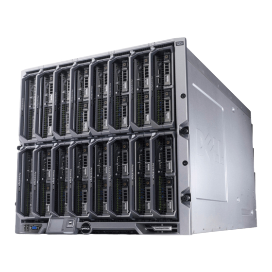
System Overview Your system can include up to 16 half-height blades (server modules), eight full-height blades, or a mixture of the two blade types (see Figure 1-1, Figure 1-2, and Figure 1-3). To function as a system, a blade is inserted into an enclosure (chassis) that supports power supplies, fan modules, a Chassis Management Controller (CMC) module, and at least one I/O module for external network connectivity. - Page 15 Figure 1-2. Blade Numbering – Full Height Blades Figure 1-3. Blade Numbering – Mixed Full-Height and Half-Height Blades About Your System...
-
Page 16: System Control Panel Features
System Control Panel Features Figure 1-4. Control Panel Features USB port (mouse only) USB port (keyboard only) video connector system power button power indicator About Your System... - Page 17 Table 1-1. Control Panel Features Item Indicator, Icon Description Button, or Connector System power Turns the system on and off. Press to turn button on the system. Press and hold 10 seconds to turn off the system. NOTE: The system power button controls power to all of the blades and I/O modules in the enclosure.
-
Page 18: Lcd Module
LCD Module The LCD module provides an initial configuration/deployment wizard, as well as easy access to infrastructure and blade information, and error reporting. See Figure 1-5. Figure 1-5. LCD Display LCD screen scroll buttons (4) selection ("check") button About Your System... -
Page 19: Lcd Module Features
LCD Module Features The primary function of the LCD module is to provide real-time information on the health and status of the modules in the enclosure. LCD module features include: • A deployment setup wizard that allows you to configure the CMC module’s network settings during initial system set up. - Page 20 Configuration Wizard The CMC is preset for DHCP . To use a static IP address, you must toggle the CMC setting from DHCP to a static address by either running the LCD Configuration Wizard, or by using a management station and CLI commands.
- Page 21 Main Menu The Main Menu options include links to the LCD Setup Menu, Server Menu, and Enclosure Menu. LCD Setup Menu You can change the default language and start-up screen for the LCD menu screens using this menu. Server Menu From the Server Menu dialog box, you can highlight each blade in the enclosure using the arrow keys, and view its status.
-
Page 22: Blade Features
Blade Features Figure 1-6. Front Panel Features – PowerEdge M600 and M605 blade handle release button hard drives (2) blade status/identification indicator USB connectors (2) blade power button blade power indicator About Your System... - Page 23 Figure 1-7. Front Panel Features – PowerEdge M910 blade handle release button hard drives (2) blade status/identification indicator USB connectors (3) blade power button blade power indicator About Your System...
- Page 24 Figure 1-8. Front Panel Features – PowerEdge M905 and M805 blade handle release button hard drives (2) blade status/identification indicator USB connectors (3) blade power button blade power indicator About Your System...
- Page 25 Figure 1-9. Front Panel Features – PowerEdge M710HD blade power indicator blade handle release button hard drives (2) blade status/identification indicator USB connectors (2) blade power button About Your System...
- Page 26 Figure 1-10. Front Panel Features – PowerEdge M710 blade handle release button hard drives (4) USB connectors (3) blade status/identification indicator blade power button blade power indicator About Your System...
- Page 27 Figure 1-11. Front Panel Features – PowerEdge M610x blade handle release button hard drive (2) expansion-card filler-bracket expansion-card slot (2) retention latch with captive screw blade status/identification indicator USB connector (2) blade power button blade power indicator About Your System...
- Page 28 Figure 1-12. Front Panel Features – PowerEdge M610 blade handle release button hard drives (2) blade status/identification indicator USB connectors (2) blade power button blade power indicator About Your System...
- Page 29 Table 1-3. Blade Control Panel Features Feature Icon Description Blade power Off – Power is not available to the blade, the blade is indicator in standby mode, the blade is not turned on, or the blade is installed incorrectly. For detailed information on installing a blade, see "Installing a Blade"...
-
Page 30: Using Usb Diskette Or Usb Dvd/Cd Drives
The USB drives can be used to configure the blade. NOTE: These blades support only Dell-branded USB 2.0 drives. The drive must be horizontal and level to operate properly. Use the optional external drive storage tray to support the drive while in use. - Page 31 The hard-disk drives plug into the internal storage backplane inside the blade. On blades with a diskless configuration, all hard drive slots must be filled with hard drive blanks, and the internal storage backplane must still be installed to maintain proper airflow. See Figure 1-13 for information on the hard-drive indicators.
- Page 32 Table 1-4. Hard-Drive Indicators Condition Drive-Status Indicator Pattern Identify drive/preparing Blinks green two times per second for removal Drive ready for insertion or removal NOTE: The drive status indicator remains off until all hard drives are initialized after system power is applied. Drives are not ready for insertion or removal during this time.
-
Page 33: Back-Panel Features
Back-Panel Features Figure 1-14. Back-Panel Features fan modules (9) primary CMC module I/O modules (6) optional iKVM module secondary CMC module power supplies (6) About Your System... - Page 34 Figure 1-15. Back-Panel Module Bay Numbering C2 B2 A2 A1 B1 C1 iKVM CMC 1 CMC 2 About Your System...
-
Page 35: Power Supply Indicator
Power Supply Indicator NOTE: The power supplies must be connected to a PDU, not directly to an electrical outlet. The power supplies require a 200-240 V power source. • A 2700 W power supply can be connected to a 110 V AC power source. •... -
Page 36: Fan Module Indicators
Table 1-5. Power Supply Indicators Indicator Icon Description Power supply Green indicates that the power supply is operational and status providing DC power to the system. Fault indicator Amber indicates a problem with the power supply, which can result from either a failed power supply or a failed fan within the power supply. -
Page 37: Ikvm Module
NOTE: The iKVM USB ports do not support storage devices. – RJ-45 ACI port for tiering with Dell™ and Avocent analog KVM and KVM over IP switches with ARI ports. NOTE: Although the ACI port is an RJ-45 connector and uses Cat5 (or better) cabling, it is not an Ethernet network interface port. - Page 38 • The iKVM can also be accessed from the front of the enclosure, providing front or rear panel KVM functionality, but not at the same time. For enhanced security, front panel access can be disabled using the CMC’s interface. NOTE: Connecting a keyboard, video, and mouse to the enclosure front panel disables video output to the iKVM back panel port.
- Page 39 Allows a monitor to be connected to the system. connector ACI port Allows connection of one or more servers to a Dell console switch with an Analog Rack Interface (ARI) port, such as an external digital or analog switch. Link indicator Off The ACI is not connected to the external switch.
-
Page 40: Tiering The Avocent Ikvm Switch From An Analog Kvm Switch
Tiering the Avocent iKVM Switch From an Analog KVM Switch The Avocent iKVM switch can be tiered from analog KVM switches such as the Dell 2160AS and 180AS, as well as many Avocent analog KVM switches. Many switches may be tiered without the need for a Server Interface Pod (SIP) (see Table 1-8). - Page 41 To connect the Avocent iKVM switch to a supported analog switch: 1 If the switch does not require a SIP to connect to the iKVM (see Table 1-8), connect a Cat5 (or newer) cable to the RJ-45 ACI port on the iKVM module.
-
Page 42: Tiering The Avocent Ikvm Switch From A Digital Kvm Switch
Connect the other end of this cable to the ARI port on the external switch. • If the switch requires a USB SIP (see Table 1-8), connect a USB SIP to the iKVM, then connect a a Cat5 (or newer) cable to the SIP. Connect the other end of this cable to the ARI port on the external switch. - Page 43 If the type you are looking for is not available, you can add it by clicking Add. 6 Click Next. The completion dialog box appears. 7 Click Finish to exit. 8 Start up the analog switch and the system. About Your System...
-
Page 44: Cmc Module
CMC Module Figure 1-19. CMC Module Features Ethernet connector Gb1 Ethernet connector STK ("stack") - used for daisy-chaining CMCs in separate enclosures link indicator (2) activity indicator (2) DB-9 serial connector for local optional secondary CMC (CMC 2) configuration primary CMC (CMC 1) amber fault indicator blue status/identification indicator power indicator... - Page 45 A fault has occurred. blinking Serial None Used for local configuration (115200 baud, No parity, connector 8, 1) The CMC provides multiple systems management functions for your modular server: • Enclosure-level real-time automatic power and thermal management. – The CMC monitors system power requirements and supports the...
- Page 46 Figure 1-19) for the system to power up. If a second, optional CMC module is installed, failover protection and hot-plug replacement is available. See the latest Dell Chassis Management Controller User's Guide at support.dell.com for complete instructions on how to set up and operate the CMC module. About Your System...
- Page 47 Figure 1-20. CMC Daisy-Chaining management network secondary CMC primary CMC About Your System...
-
Page 48: I/O Connectivity
I/O Connectivity The M1000e enclosure supports three layers of I/O fabric, selectable between combinations of Ethernet, fibre-channel, and Infiniband modules. You can install up to six hot-swappable I/O modules in the enclosure, including fibre- channel switches, fibre-channel pass-throughs, Infiniband switches, Ethernet switches, and Ethernet pass-through modules. -
Page 49: Port Auto-Disablement In Quad-Port Network Daughter Card (M710Hd Only)
Fabric B Fabric B is a dual port, 1 to 10 Gb/sec , quad-lane redundant fabric, supporting I/O module slots B1 and B2. Fabric B currently supports Ethernet, Infiniband, and Fibre Channel modules. To communicate with an I/O module in the Fabric B slots, a blade must have a matching mezzanine card installed in a Fabric B mezzanine card location. -
Page 50: Mezzanine Cards
Table 1-11. Port Auto-Disablement Decision Table IOM Slot A1 IOM Slot A2 NIC3 and NIC4 Port Auto- (Enabled/Disabled) Disablement Empty Empty Enabled Inactive Empty Dual Port Disabled Active Empty Quad or Greater Enabled Inactive Port Dual Port Empty Disabled Active Dual Port Dual Port Disabled... - Page 51 Full-Height Blades Full-height blades support four mezzanine cards: • Slot Mezz1_Fabric_C and slot Mezz3_Fabric_C support Fabric C. They must match the fabric type of the I/O modules installed in I/O module slots C1 and C2. • Slot Mezz2_Fabric_B and slot Mezz4_Fabric_B support Fabric B. They must match the fabric type of the I/O modules installed in I/O module slots B1 and B2.
- Page 52 (continued) Table 1-12. Supported I/O Module Configurations Fabric A Fabric B Fabric C I/O Bay A1, I/O Bay B1, I/O Bay C1, Mezzanine Mezzanine Card Card Standard none Infiniband Ethernet none Infiniband Integrated mezzanine switch switch card module or module pass- through module...
- Page 53 (continued) Table 1-12. Supported I/O Module Configurations Fabric A Fabric B Fabric C I/O Bay A1, I/O Bay B1, I/O Bay C1, Mezzanine Mezzanine Card Card Standard Ethernet Fibre Ethernet Ethernet Fibre Integrated mezzanine Channel switch switch Channel card mezzanine module or module or switch or...
-
Page 54: I/O Module Port Mapping
Integrated LOM1, connection 2 connects to I/O module A2, port n. • Integrated LOM2, connection 1 connects to I/O module A1, port n+8. Integrated LOM2, connection 2 connects to I/O module A2, port n+8. For example, in a full-height blade in slot 5, integrated LOM1 connection 1 connects to I/O module A1, port 5 and LOM1 connection 2 connects to I/O module A2 port 5. - Page 55 • Mezzanine card 3, connection 1 connects to I/O module C1, port n+8. Mezzanine card 3, connection 2 connects to I/O module C2 port n+8. Mezzanine card 4, connection 1 connects to I/O module B1, port n+8. • Mezzanine card 4, connection 2 connects to I/O module B2 port n+8.
- Page 56 Figure 1-21. Example of M610x Blade Port Mapping of – Blade 2 About Your System...
- Page 57 Table 1-14. I/O Module Port Assignments - Full-Height Blades (not applicable to M610x) Blade 1 I/O Module Mezz1_Fab_C Port 1 Port 1 Mezz2_Fab_B Port 1 Port 1 Mezz3_Fab_C Port 9 Port 9 Mezz4_Fab_B Port 9 Port 9 Blade 2 I/O Module Mezz1_Fab_C Port 2 Port 2...
- Page 58 Blade 4 I/O Module Mezz1_Fab_C Port 4 Port 4 Mezz2_Fab_B Port 4 Port 4 Mezz3_Fab_C Port 12 Port 12 Mezz4_Fab_B Port 12 Port 12 Blade 5 I/O Module Mezz1_Fab_C Port 5 Port 5 Mezz2_Fab_B Port 5 Port 5 Mezz3_Fab_C Port 13 Port 13 Mezz4_Fab_B Port 13...
- Page 59 Blade 8 I/O Module Mezz1_Fab_C Port 8 Port 8 Mezz2_Fab_B Port 8 Port 8 Mezz3_Fab_C Port 16 Port 16 Mezz4_Fab_B Port 16 Port 16 Figure 1-22 shows the port connections for a full-height blade in bay 3 with four mezzanine cards.
- Page 60 Table 1-15. I/O Module Port Assignments—Full-Height Blades (not applicable to M610x) Blade and Blade ( + 8) I/O Module NOTE: n denotes a variable value from 1 to 8. Mezz_FAB_B_Blade n_Port1 Port n Mezz_FAB_B_Blade n_Port2 Port n Mezz_FAB_B_Blade n_Port3 Port (n+16) Mezz_FAB_B_Blade n_Port4 Port...
- Page 61 (continued) Table 1-15. I/O Module Port Assignments—Full-Height Blades (not applicable to M610x) Blade and Blade ( + 8) I/O Module NOTE: n denotes a variable value from 1 to 8. Mezz_FAB_C_Blade Port n+8_Port2 (n+8) Mezz_FAB_C_Blade Port n+8_Port3 (n+24) Mezz_FAB_C_Blade Port...
- Page 62 Half-Height Blades Standard LOM (Dual-Port) and Network Daughter Card (Quad-Port) Mapping Each standard LOM has two port connections. For a half-height blade in bay n: • Integrated LOM, connection 1 connects to I/O module A1, port n. Integrated LOM, connection 2 connects to I/O module A2, port n. Half-height blades with Network Daughter Card (M710HD) hosts two network controllers (LOM1 and LOM2), each with two port connections.
- Page 63 Dual-Port Mezzanine Cards For a half-height blade in bay n: The integrated NIC connects to I/O module A1, port n and I/O module • A2, port n. • Mezzanine card B connects to I/O module B1, port n and I/O module B2, port n.
- Page 64 Figure 1-23. Example of Half-Height Blade Port Mapping About Your System...
- Page 65 1 to 16. NOTE: For a detailed mapping of each PowerEdge system, see the document Quadport Capable Hardware For the M1000e Modular Chassis on support.dell.com/manuals. Table 1-18. I/O Module Port Assignments—Half-Height Blades Blade I/O Module Integrated LOM1...
-
Page 66: Mellanox M3601Q Qdr Infiniband Switch I/O Module
Mellanox M3601Q QDR Infiniband Switch I/O Module The Mellanox M3601 Infiniband switch I/O module includes 32 4x QDR Infiniband ports. Of these, 16 ports are external uplink ports, while 16 internal ports provide connectivity to the blades in the enclosure. This module occupies two I/O module slots. -
Page 67: Mellanox M2401G Infiniband Switch I/O Module
Infiniband ports. Eight ports are external uplink ports, while 16 internal ports provide connectivity to the blades in the enclosure. Figure 1-25. Mellanox M2401G Infiniband Switch Module Infiniband ports (8) port link status indicators (8) port activity indicators (8) module diagnostic power indicator module status indicator... - Page 68 Table 1-19. Mellanox M2401G Infiniband Switch Indicators Indicator Pattern Description Link indicator Green, on Physical link established Green, off No physical link present Activity indicator Amber, on Valid logical link to Infiniband network established Amber, blinking Data transfer is occurring Amber, off No logical link to Infiniband network About Your System...
-
Page 69: Cisco Sfs M7000E Infiniband Switch Module
Fabric B or Fabric C. For general information on installing this module, see "I/O Modules" on page 274. Figure 1-26. Cisco SFS M7000e Infiniband Switch Module Features Infiniband ports (8) port status indicator (8) diagnostic status indicator power indicator About Your System... -
Page 70: Cisco Ethernet Switch
Table 1-20. Cisco SFS M7000e Infiniband Switch Indicators Indicator Type Pattern Description Infiniband Link error or Subnet Manager not operating port status Green flickering I/O activity on port indicator Green on Link established Module status Switch is not ready indicator Blue on Switch operating normally Amber on or... - Page 71 Figure 1-27. Cisco Ethernet Switch Module Features Stackwise Plus connectors (not 10/100/1000 Mb Ethernet enabled in CBS 3032) connectors (4) option bays (2) Cisco status indicators mode button console port for switch management power indicator status/identification indicator About Your System...
-
Page 72: Powerconnect M6348 1 Gb Ethernet Switch I/O Module
PowerConnect M6348 1 Gb Ethernet Switch I/O Module The PowerConnect M6348 is a hot-swappable 48-port 1 Gb Ethernet switch. While 16 ports are external uplink ports, the remaining 32 internal ports provide connectivity to the blades within the enclosure with a maximum bandwidth of 1 Gbps each. - Page 73 Figure 1-28. PowerConnect M6348 Switch Module standard 10/100/1000 Mb SFP+ connectors (2) Ethernet connectors (16) CX4 stacking connectors (2) console management connector power indicator status/identification indicator About Your System...
-
Page 74: Powerconnect M8024 10 Gb Ethernet Switch I/O Module
PowerConnect M8024 10 Gb Ethernet Switch I/O Module The PowerConnect M8024 switch module incorporates two option bays that support the following modules: • A 10 Gb Ethernet module with four optical SFP+ connectors • A 10 Gb Ethernet module with three copper CX4 uplinks You can initially configure the switch using either of two methods: •... - Page 75 Figure 1-29. PowerConnect M8024 Switch Module optional module with four SFP+ optional module with three CX4 ports ports serial connector for optional USB power indicator type-A form-factor cable status/identification indicator About Your System...
-
Page 76: Powerconnect M6220 Ethernet Switch Module
PowerConnect M6220 Ethernet Switch Module The PowerConnect M6220 Ethernet switch module includes four external 10/100/1000 Mbps Ethernet connectors and one USB type A form factor serial connector. See Figure 1-30. Two option bays support the following three module options: • A resilient stacking module with 2 x 24 Gb stacking ports •... - Page 77 Figure 1-30. PowerConnect M6220 Ethernet Switch Module Features optional module (2) (dual 10 Gb standard 10/100/1000 Mb Ethernet Ethernet uplink module shown) connectors (4) serial connector (USB type-A form power indicator factor) status/identification indicator About Your System...
-
Page 78: Gb Ethernet Pass-Through Module
10 Gb Ethernet Pass-Through Module II The Dell 10 Gb Ethernet pass-through module II supports 10 Gb connections and provides a direct connection between the optional internal Ethernet mezzanine card in the blade and an external Ethernet device. The Ethernet pass-through modules are hot-swappable and may be installed in Fabric B or Fabric C. - Page 79 Figure 1-31. 10 Gb Ethernet Pass-Through Module II SFP+ cages (16) green/amber indicators (two per port) status/identification indicator power indicator About Your System...
-
Page 80: 10 Gb Ethernet Pass-Through I/O Module
10 Gb Ethernet Pass-Through I/O Module The 10 Gb Ethernet pass-through module supports 1/10 Gb connections and provides a direct connection between the optional internal Ethernet mezzanine card in the blade and an external Ethernet device. The Ethernet pass-through modules are hot-swappable and may be installed in Fabric B or Fabric C. - Page 81 Figure 1-32. 10 Gb Ethernet Pass-Through I/O Module Features SFP+ cages (16) green/amber indicators (two per port) power indicator status/identification indicator About Your System...
-
Page 82: Gbps Fibre Channel Pass-Through Module
4 Gbps Fibre Channel Pass-Through Module The 4 Gbps Fibre Channel pass-through module provides a bypass connection between a Fibre Channel mezzanine card in the blade and optical transceivers for direct connection into a Fibre Channel switch or a storage array (see Figure 1-33). - Page 83 Figure 1-33. 4 Gbps Fibre Channel Pass-Through Module Features SFP Fibre Channel connector (16) Fibre Channel green/amber indicators (two per port) power indicator status/identification indicator About Your System...
- Page 84 Table 1-21. Fibre Channel Pass-Through Indicators Indicator Type Pattern Description Power Power to the module is off indicator Green Module has power Status/ Blue on Primary module in a stack, if applicable identification Blue off Secondary module in a stack indicator Amber flashing Fault condition in module...
-
Page 85: Brocade M5424 Fc8 I/O Module
16 internal ports, and one serial port with an RJ-45 connector. The external Fibre Channel ports operate at 8 Gb/sec, 4 Gb/sec, or 2 Gb/sec. NOTE: CMC firmware version 1.3 is required to support FC8 mezzanine cards and I/O modules. - Page 86 Figure 1-34. Brocade M5424 FC8 I/O Module Fibre Channel port (8) Fibre Channel port status indicator (8) Fibre Channel port speed serial port (RJ-45 connector) indicator (8) module status indicator power indicator status/identification indicator About Your System...
- Page 87 2 Gb link established port speed Green on 4 Gb link established indicator Amber on 8 Gb link established Module status Module is off or enclosure power is off indicator Green on All ports are ready for use Amber on...
-
Page 88: Brocade M4424 San I/O Module
Brocade M4424 SAN I/O Module The Brocade M4424 SAN I/O module includes eight external autosensing Fibre Channel ports (four ports are enabled in the standard configuration and four additional ports may be enabled as an optional upgrade), 16 internal ports, and one serial port with an RJ-45 connector. The external Fibre Channel ports operate at 1 Gb/sec, 2 Gb/sec, or 4 Gb/sec. - Page 89 Figure 1-35. Brocade M4424 SAN I/O Module Features Fibre Channel port (8) Fibre Channel port status indicator (8) Fibre Channel port speed serial port (RJ-45 connector) indicator (8) module status indicator power indicator status/identification indicator About Your System...
- Page 90 Table 1-23. Brocade M4424 SAN I/O Module Indicators Indicator Type Pattern Description Fibre Channel No signal carrier port status Amber on Signal present but not online indicator Green on Online, but no activity Green blinking Online but segmented slowly Green blinking Internal loopback quickly Green flickering...
-
Page 91: 10/100/1000 Mb Ethernet Pass-Through Module
10/100/1000 Mb Ethernet Pass-Through Module The Ethernet pass-through module supports 10/100/1000 Mb connections, and provides a direct connection between the optional internal Ethernet mezzanine card in the blade and an external Ethernet device (see Figure 1-36). The Ethernet pass-through modules are hot-swappable, and may be installed in any of the three Fabrics. - Page 92 link indicator (16) activity indicator (16) RJ45 Ethernet connector (16) power indicator status/identification indicator NOTE: Connectors on the Ethernet pass-through module correspond directly to the blade number. For example, blade 5 is connected to port 5 on the Ethernet pass- through module.
-
Page 93: Lcd Status Messages
LCD Status Messages The following LCD messages refer to events recorded in the System Event Log (SEL). (The messages are shown here in "simple" text format.) For information on the SEL and configuring system management settings, see the systems management software documentation. NOTE: If your system fails to boot, press the System ID button for at least five seconds until an error code appears on the LCD. - Page 94 (continued) Table 1-25. LCD Status Messages Code Text Cause Corrective Actions Ambient temperature has See "Troubleshooting Fan E1114 Ambient Temp reached a point outside of Modules" on page 293. exceeds the allowed range. allowed range. Memory has exceeded Remove AC power to the E1116 Memory allowable temperature and system for 10 seconds and...
- Page 95 (continued) Table 1-25. LCD Status Messages Code Text Cause Corrective Actions Specified processor Reseat the processor(s). E1229 CPU # VCORE VCORE voltage regulator See "Troubleshooting Regulator has failed. Processors" on page 300. failure. Reseat CPU. If the problem persists, see "Getting Help" on page 337.
-
Page 96: Cpu Heatsink
(continued) Table 1-25. LCD Status Messages Code Text Cause Corrective Actions Speed of the specified fan See "Troubleshooting Fan E1311 Fan module ## in specified module is Modules" on page 293. RPM exceeding outside of intended range. Check operating range. fan. - Page 97 (continued) Table 1-25. LCD Status Messages Code Text Cause Corrective Actions The system BIOS has Remove AC power to the E141F CPU # reported a processor system for 10 seconds and protocol protocol error. restart the system. error. Power cycle AC. If the problem persists, see "Getting Help"...
- Page 98 (continued) Table 1-25. LCD Status Messages Code Text Cause Corrective Actions Specified power supply has See "Troubleshooting E1618 Predictive detected a condition that Power Supply Modules" failure on may predict a future power- on page 292. Power Supply down event, such as an # (### W).
-
Page 99: Clear Sel
(continued) Table 1-25. LCD Status Messages Code Text Cause Corrective Actions The system configuration Turn off power to the E1629 Power requires more power than system, reduce the required > the power supplies can hardware configuration or PSU wattage. provide, even with install higher-wattage Check PSU and throttling. - Page 100 (continued) Table 1-25. LCD Status Messages Code Text Cause Corrective Actions Memory configured, but is See "Troubleshooting E2012 Memory unusable. Blade Memory" on configured page 297. but unusable. Check DIMMs. The system BIOS failed to See "Troubleshooting E2013 BIOS unable copy its flash image into Blade Memory"...
- Page 101 (continued) Table 1-25. LCD Status Messages Code Text Cause Corrective Actions Programmable interval Remove AC power to the E2018 Programmable timer error. system for 10 seconds and Timer error. restart the system. Power cycle If the problem persists, see "Getting Help" on page 337.
-
Page 102: User Guide
(continued) Table 1-25. LCD Status Messages Code Text Cause Corrective Actions BIOS shutdown test failure. Remove AC power to the E201D Shutdown test system for 10 seconds and failure. restart the system. Power cycle If the problem persists, see "Getting Help" on page 337. - Page 103 (continued) Table 1-25. LCD Status Messages Code Text Cause Corrective Actions The system BIOS has Remove AC power to the E2111 SBE log disabled memory single-bit system for 10 seconds and disabled on error (SBE) logging and restart the system. DIMM ##.
- Page 104 NOTE: For the full name of an abbreviation or acronym used in this table, see the Glossary at support.dell.com/manuals. About Your System...
-
Page 105: System Messages
Damage due to servicing that is not authorized by Dell is not covered by your warranty. Read and follow the safety instructions that came with the product. - Page 106 (continued) Table 1-26. Blade Messages Message Causes Corrective Actions This warning occurs if Ensure that the expansion- Warning: PCIe BIOS does not discover card riser is installed in the expansion riser the expansion-card riser system, If applicable, not found. Check during POST.
- Page 107 (continued) Table 1-26. Blade Messages Message Causes Corrective Actions Applicable to both base Verify that the PCIe Current Overlimit blade and expansion. expansion cards installed do detected in not have power Expansion NOTE: Applicable to M610x consumption more than only. 250 W.
-
Page 108: Dimm Configuration
(continued) Table 1-26. Blade Messages Message Causes Corrective Actions Invalid configuration. The Ensure that the memory Memory system will run but with modules are installed in a Initialization less memory than is valid configuration. See Warning: Memory physically installed. "System Memory" on size may be page 159. - Page 109 (continued) Table 1-26. Blade Messages Message Causes Corrective Actions The memory Reconfigure the memory 128-Bit Advanced configuration does not modules to support ECC Mode Disabled match the setting in BIOS. Advanced ECC mode. See - For 128-Bit The BIOS setting has been "System Memory"...
-
Page 110: System Halted
(continued) Table 1-26. Blade Messages Message Causes Corrective Actions Invalid memory Ensure that the memory MEMTEST lane configuration. A modules are installed in a failure detected mismatched DIMM is valid configuration. See installed. "System Memory" on page 159. Processors with Mismatched processors are Ensure that all processors installed. - Page 111 (continued) Table 1-26. Blade Messages Message Causes Corrective Actions The installed memory Ensure that the memory Alert: DIMM_[m] configuration is invalid. modules are installed in and DIMM_[n] must matched pairs. See "System be populated with Memory" on page 159. a matched set of DIMMs if more than 1 DIMM is present.
-
Page 112: System Board
(continued) Table 1-26. Blade Messages Message Causes Corrective Actions The installed memory Add, move, or remove Alert! Unsupported configuration is invalid. memory modules to achieve memory, incomplete a configuration supported by sets, or unmatched the system. See "System sets. The Memory"... - Page 113 (continued) Table 1-26. Blade Messages Message Causes Corrective Actions The memory modules are Replace or reseat the DIMMs <A1-A8> not properly seated. memory module(s). See disabled - MemBIST "System Memory" on error. The memory module page 159. connector may be exposed DIMMs <A1-A8>...
- Page 114 (continued) Table 1-26. Blade Messages Message Causes Corrective Actions Mismatched or Ensure that all pairs of DIMMs should be unmatched DIMMs memory modules are of the installed in installed; faulty or same type and size and that pairs. Pairs must improperly installed they are properly installed.
- Page 115 (continued) Table 1-26. Blade Messages Message Causes Corrective Actions Mismatched or Ensure that all pairs of Error: Incorrect unmatched DIMMs memory modules are of the memory installed; faulty or same type and size, and that configuration. improperly seated memory they are properly installed. DIMMs must be modules.
- Page 116 Branch x. or your Dell sales agent to ensure compatibility. Faulty keyboard controller See "Getting Help" on Gate A20 failure. (faulty blade board). page 337.
- Page 117 (continued) Table 1-26. Blade Messages Message Causes Corrective Actions Mouse or keyboard cable is Reseat the mouse or Error 8602 - loose or improperly keyboard cable. Ensure that Auxiliary Device connected. the mouse or keyboard is Failure. operational. See Defective mouse or Verify that mouse "Troubleshooting USB keyboard.
- Page 118 (continued) Table 1-26. Blade Messages Message Causes Corrective Actions The spacebar or ESC key Information only. Memory tests was pressed during POST terminated by to terminate the memory keystroke. test. Keyboard cable connector Ensure that the keyboard is Keyboard data line loose or improperly properly connected.
-
Page 119: Bios Update
(continued) Table 1-26. Blade Messages Message Causes Corrective Actions Faulty or improperly Reseat the mezzanine card. PCI BIOS failed to installed mezzanine card. See "I/O Module Mezzanine install. Cards" on page 198. If the problem persists, see "Getting Help" on page 337. Error encountered in Set the NVRAM_CLR Plug &... - Page 120 Restore the flash memory System service Card flash memory may be using the latest version on update required. ftp.dell.com or corrupted. support.dell.com. See the iDRAC6 User’s Guide for instructions on performing a field replacement of the flash memory. About Your System...
- Page 121 (continued) Table 1-26. Blade Messages Message Causes Corrective Actions Faulty memory module. See "Troubleshooting Blade The amount of Memory" on page 297. If the system memory has problem persists, see changed. "Getting Help" on page 337. Unsupported processor(s) Replace the processor(s) This system does installed.
-
Page 122: Reset The System
See combination. "Processors" on page 225. Processor is not supported by the blade. Check for a BIOS update using the Dell Support website at support.dell.com. Processor is not supported Check for a BIOS update Unsupported CPU by the blade. - Page 123 Memory" on page 297. faulty DIMMs are disabled: DIMMxx, DIMMyy. Unsupported processor. Update the BIOS firmware Warning! No using the Dell Support microcode update website at support.dell.com. loaded for processor n. There is no memory See "System Memory" on Warning: The configuration error, but page 159.
- Page 124 NOTE: For the full name of an abbreviation or acronym used in this table, see the Glossary at support.dell.com/manuals. A warning message alerts you to a possible problem and prompts you to respond before the system continues a task. For example, before you format a diskette, a message warns you that you may lose all data on the diskette.
-
Page 125: Diagnostics Messages
NOTE: Warning messages are generated by either the application or the operating system. For more information, see the documentation that accompanied the operating system or application. Diagnostics Messages When you run system diagnostics, an error message may result. Diagnostic error messages are not covered in this section. Record the message on a copy of the Diagnostics Checklist in "Getting Help"... - Page 126 About Your System...
-
Page 127: Using The System Setup Program
Using the System Setup Program and UEFI Boot Manager The System Setup program is the BIOS program that enables you to manage your system hardware and specify BIOS-level options. From the System Setup program, you can: • Change the NVRAM settings after you add or remove hardware •... -
Page 128: Entering The System Setup Program
Entering the System Setup Program 1 Turn on or restart your system. 2 Press <F2> immediately after you see the following message: <F2> = System Setup If your operating system begins to load before you press <F2>, allow the system to finish booting, and then restart your system and try again. Responding to Error Messages If an error message appears while the system is booting, make a note of the message. -
Page 129: System Setup Options
System Setup Options NOTE: The options for the System Setup program change based on the system configuration. NOTE: The System Setup program defaults are listed under their respective options, where applicable. Option Description System Time Sets the time on the system's internal clock. System Date Sets the date on the system's internal calendar. -
Page 130: Memory Settings Screen
Option Description F1/F2 Prompt on Enables the system to halt on errors during POST, which Error (Enables allows the user to observe events that may scroll by unnoticed default) during normal POST. You can select <F1> to continue or <F2> to enter the System Setup program. CAUTION: When setting this option to Disabled, the system does not halt if an error occurs during POST. -
Page 131: Processor Settings Screen
Option Description Redundant Memory If a valid memory configuration is installed, you can enable (PowerEdge M910, memory mirroring or spare memory. Options are Mirror M710HD, and M600) Mode, Spare Mode, and Disabled. ® ® NOTE: M710HD systems installed with Intel Xeon 5600 series processors support memory sparing. -
Page 132: Sata Settings Screen (Poweredge M610, M610X)
Option Description Adjacent Cache Line Enable or disables system optimization for sequential Prefetch memory access. (Enabled default) Hardware Prefetcher Enables or disables the hardware prefetcher. (Enabled default) DCU Streamer Enables or disables DCU streamer prefetcher. Prefetcher (Enabled default) Data Reuse Enables or disables data reuse in cache. -
Page 133: Boot Settings Screen
Boot Settings Screen Option Description Boot Mode (BIOS If the operating system supports Unified Extensible default) Firmware Interface, set this option to UEFI. Setting this field to BIOS allows compatibility with non-UEFI (PowerEdge M910, M710, M710HD, M610, and operating systems. M610x) NOTE: Setting this field to UEFI disables the Boot... - Page 134 Option Description Internal USB Port Enables or disables the system’s internal USB port. (PowerEdge M910, M710, M710HD, M610, and M610x) Internal SD Card Port Enables or disables the system’s internal SD card port. (PowerEdge M910, NOTE: If a hypervisor is installed, it uses this port. M905, M805, M710, M710HD, M610 and M610x)
-
Page 135: Pci Irq Assignments Screen
Option Description OS Watchdog Timer If set to Enabled, the operating system restarts the system (Disabled default). if it locks up, based on the expiration of a timer. If set to Disabled, in the event of a system lockup, no timer is set and the OS does not restart the system in the event of a lockup. -
Page 136: Power Management Screen(Poweredge M910, M710, M710Hd, M610 And M610X Only)
Option Description Remote Terminal Type Select either VT 100/VT 220 or ANSI. (VT 100/VT 220 default) Redirection After Boot Enables or disables BIOS console redirection after your (Enabled default) system boots to the operating system. Power Management Screen (PowerEdge M910, M710, M710HD, M610 and M610x Only) Option Description... -
Page 137: System Security Screen
System Security Screen Option Description System Password Displays the current status of the password security feature and allows a new system password assignment and verification. NOTE: For more information, see "Using the System Password" on page 140. Setup Password Restricts access to the System Setup program by using a setup password. -
Page 138: Exit Screen
Option Description NOTE: Clearing the TPM loses all encryption keys in the TPM Clear TPM. This option prevents booting to the operating system (No default) and results in data loss if the encryption keys cannot be restored. Back up the TPM keys prior to enabling this option. -
Page 139: Entering The Uefi Boot Manager
Entering the UEFI Boot Manager 1 Turn on or restart your system. 2 Press <F11> after you see the following message: <F11> = UEFI Boot Manager NOTE: The system does not respond until the USB keyboard is active. NOTE: The Boot Mode option in System Setup must be set to UEFI to access the UEFI Boot Manager. -
Page 140: System Utilities Screen
System Utilities Screen Option Description System Setup Accesses the System Setup program without rebooting. System Services Restarts the system and accesses the Unified Server Configurator, which allows you to run utilities such as system diagnostics. For more information, see the Unified Server Configurator User’s Guide. - Page 141 When a system password is not assigned and the password jumper on the system board is in the enabled position, System Password is Not Enabled and Password Status is Unlocked. To assign a system password: 1 Verify that Password Status is Unlocked. 2 Highlight the System Password option and press <Enter>.
-
Page 142: Using The Setup Password
To disable the password security: 1 Turn on or reboot your system by pressing <Ctrl><Alt><Del>. 2 Type your password and press <Ctrl><Enter>. When Password Status is Locked, you must type the password and press <Enter> when prompted at reboot. If an incorrect system password is entered, the system displays a message and prompts you to re-enter your password. - Page 143 As you type, placeholders appear in the field. The password assignment is not case-sensitive. Certain key combinations are invalid and if you enter one, the system beeps. To erase a character, press <Backspace> or the left-arrow key. When you verify the password, the Setup Password changes to Enabled. The next time you enter the System Setup program, the system prompts you for the setup password.
- Page 144 Using the System Setup Program and UEFI Boot Manager...
-
Page 145: Installing Blade Components
Installing Blade Components Recommended Tools You may need the following items to perform the procedures in this section: • #1 and #2 Phillips screwdrivers • T8 and T10 Torx drivers • Wrist grounding strap Removing and Installing a Blade Removing a Blade 1 Power down the blade using OS commands or the CMC, and ensure that the blade's power is off. - Page 146 Figure 3-1. Removing and Installing a Half-Height Blade blade handle release button blade guide rail on M1000e enclosure guide rail on blade (or blade blank) Installing Blade Components...
- Page 147 Figure 3-2. Removing and Installing a Full-Height Blade blade handle release button blade guide rail on M1000e enclosure guide rail on blade Installing Blade Components...
-
Page 148: Installing A Blade
Installing a Blade 1 If you are installing a new blade, remove the plastic cover from the I/O connector(s) and save for future use. See Figure 3-3. 2 Orient the blade so that the handle is on the left side of the blade. 3 If you are installing a blade in one of the eight upper bays, align the guide rail on the upper edge of the blade so that the rail fits between the plastic guides on the enclosure. -
Page 149: Installing A Blade Blank
Installing a Blade Blank 1 Hold the blank with the guide rail facing upwards (see detail in Figure 3-1). 2 Install the blank in the enclosure: If you are installing a blade blank in one of the eight upper bays, align •... - Page 150 Figure 3-3. Opening a Blade (PowerEdge M600 Shown) cover-release latch chassis cover I/O connector cover Installing Blade Components...
- Page 151 Figure 3-4 through Figure 3-11 show the interior components in the blades. Figure 3-4. Inside a Half-Height Blade (PowerEdge M710HD Shown) iDRAC enterprise card optional mezzanine card 1 - Fabric C optional mezzanine card 2 - network daughter card Fabric B memory modules (A1 to A9) processor CPU2 and heat sink hard drives (2)
- Page 152 Figure 3-5. Inside a Half-Height Blade (PowerEdge M600 Shown) optional Fabric C mezzanine card 2 optional Fabric B mezzanine card memory modules processor CPU1 and heat sink hard-drive backplane storage controller card (under drive bays) hard drive 1 hard drive 0 processor CPU2 and heat sink video riser card Installing Blade Components...
- Page 153 Figure 3-6. Inside a Half-Height Blade (PowerEdge M610 Shown) optional mezzanine card optional mezzanine card - Mezz1_Fab_C Mezz2_Fab_B memory modules processor CPU2 and heat sink hard-drive backplane storage controller card (under drive bays) hard drive 1 hard drive 0 processor CPU1 and heat sink iDRAC6 Enterprise card (under mezzanine card Installing Blade Components...
- Page 154 Figure 3-7. Inside a Full-Height Blade (PowerEdge M910 Shown) optional mezzanine card 1 - optional mezzanine card 2 - Fabric C Fabric B optional mezzanine card 3 - optional mezzanine card 4 - Fabric C Fabric B processor CPU2 and heat sink processor CPU4 hard drive 1 hard drive 0...
- Page 155 Figure 3-8. Inside a Full-Height Blade (PowerEdge M905 Shown) optional mezzanine card 1 - optional mezzanine card 2 - Fabric C Fabric B optional mezzanine card 3 - optional mezzanine card 4 - Fabric C Fabric B SD card location...
- Page 156 Figure 3-9. Inside a Full-Height Blade (PowerEdge M805 Shown) optional mezzanine card 1 - optional mezzanine card 2 - Fabric C Fabric B optional mezzanine card 3 - optional mezzanine card 4 - Fabric C Fabric B SD card location processor CPU2 and heat sink processor CPU2 and heat sink hard drive 1...
- Page 157 Figure 3-10. Inside a Full-Height Blade (PowerEdge M710 Shown) optional mezzanine card 1 - optional mezzanine card 2 - Fabric C Fabric B optional mezzanine card 3 - optional mezzanine card 4 - Fabric C Fabric B memory modules processor CPU2 and heat sink hard drives (4) hard-drive backplane processor CPU1 and heat sink...
- Page 158 Figure 3-11. Inside a Full-Height Blade (PowerEdge M610x Shown) internal SD vFalsh card slot iDRAC6 Enterprise card mezzanine interface card midplane interface card optional mezzanine card optional mezzanine card - Mezz1_Fab_C1 Mezz2_Fab_B1 PCIe riser Standard PCIe cards or PCIe expansion-card blanks hard-drive backplane processor CPU2 and heat sink memory modules (B1 to B6)
-
Page 159: Closing The Blade
DIMMs per channel. This configuration permits the following maximum memory configurations: Up to four 2 GB, 4 GB, 8 GB, and 16 GB RDIMMs are supported per channel, for a total of up to 512 GB. Single-rank, dual rank, and quad-rank RDIMMs are supported. - Page 160 Figure 3-12. Memory Locations - PowerEdge M910 Installing Blade Components...
- Page 161 B7, B8, C1, C2, C3, C4, C5, C6, C7, C8, D1, D2, D3, D4, D5, D6, D7, D8 128 GB Sixteen 8 GB A1, A2, A3, A4, B1, B2, B3, B4, C1, C2, C3, C4, D1, D2, D3, D4 Installing Blade Components...
- Page 162 192 GB Twenty-four 8 GB A1, A2, A3, A4, A5, A6, B1, B2, B3, B4, B5, B6, C1, C2, C3, C4, C5, C6, D1, D2, D3, D4, D5, D6...
-
Page 163: System Memory - Poweredge M905
You can upgrade your system memory to a maximum of 192 GB by installing up to twenty-four 667 MHz registered DDR2 memory modules in sets of 1 GB, 2 GB, 4 GB, or 8 GB memory modules. (Dual-rank 8 GB modules are supported; quad-rank 8 GB modules are not supported.) Each processor has four memory channels, organized in sets of two channels. - Page 164 – Figure 3-13. Memory Locations PowerEdge M905 General Memory Module Installation Guidelines – PowerEdge M905 To ensure optimal performance of your system, observe the following guidelines when configuring your system memory: • Memory modules must be installed in pairs, beginning with the first two sockets in each set of memory modules.
- Page 165 A1, A2, A3, A4, A5, A6, A7, A8, B1, B2, B3, B4, B5, B6, B7, B8, C1, C2, C3, C4, D1, D2, D3, D4 64 GB* Eight 8 GB A1, A2, B1, B2, C1, C2, D1, D2 64 GB* Sixteen 4 GB...
-
Page 166: System Memory - Poweredge M805
667 MHz registered DDR2 memory modules in sets of 1 GB, 2 GB, 4 GB, or 8 GB memory modules. (Dual-rank 8 GB modules are supported; quad-rank 8 GB modules are not supported.) Each processor has four memory channels, organized in sets of two channels. - Page 167 – Figure 3-14. Memory Locations PowerEdge M805 General Memory Module Installation Guidelines – PowerEdge M805 To ensure optimal performance of your system, observe the following guidelines when installing your system memory: • Memory modules must be installed in pairs of identically-sized DIMMs, beginning with slots A1 and A2 (processor 1) and B1 and B2.
- Page 168 Memory Module Locations System Number and Size Memory 4 GB Four 1 GB A1, A2, B1, B2 8 GB Eight 1 GB A1, A2, A3, A4, B1, B2, B3, B4 8 GB Four 2 GB A1, A2, B1, B2 12 GB...
- Page 169 Memory Module Locations System Number and Size Memory 64 GB* Eight 8 GB A1, A2, A3, A4, B1, B2, B3, B4 128 GB Sixteen 8 GB A1, A2, A3, A4, A5, A6, A7, A8, B1, B2, B3, B4, B5, B6, B7, B8 *If 64 GB of memory is installed, the system recognizes only 63.75 GB during POST.
-
Page 170: System Memory - Poweredge M710
• Up to three 1 GB, 2 GB, 4 GB, and 8 GB RDIMMs (when available) are supported per channel, for a total of up to 144 GB. Single-rank, dual rank, and quad-rank RDIMMs are supported. - Page 171 – Figure 3-15. Memory Locations PowerEdge M710 Channel 2 (B1, B4, B7) Channel 1 (B2, B5, B8) Channel 0 (B3, B6, B9) Channel 0 (A3, A6, A9) Channel 1 A2, A5, A8) Channel 2 (A1, A4, A7) Installing Blade Components...
- Page 172 The channels are organized as follows: • Channel 0 - sockets 3, 6, 9 • Channel 1 - sockets 2, 5, 8 • Channel 2 - sockets 1, 4, 7 Sockets A1 through A9 are assigned to CPU1; sockets B1 through B9 are assigned to CPU2.
- Page 173 A1, A2, A3, B1, Independent 6 GB UDIMMs B2, B3 channel 6 GB Three 2 GB A1, A2, A3 Independent 6 GB UDIMMs channel 8 GB Four 2 GB A2, A3, B2, B3 Mirroring 4 GB UDIMMs Installing Blade Components...
- Page 174 Nine 4 GB A1, A2, A3, A4, Independent 36 GB RDIMMs A5, A6, A7, A8, channel 64 GB Eight 8 GB A2, A3, A5, A6, Mirroring 32 GB RDIMMs B2, B3, B5, B6 64 GB Eight 8 GB A2, A3, A5, A6,...
- Page 175 72 GB RDIMMs A5, A6, A7, A8, channel A9, B1, B2, B3, B4, B5, B6, B7, B8, B9 96 GB Twelve 8 GB* A1, A2, A3, A4, Independent 96 GB RDIMMs A5, A6, B1, B2, channel B3, B4, B5, B6...
-
Page 176: System Memory - Poweredge M710Hd
DIMMs per channel. This configuration supports up to three 2 GB, 4 GB, 8 GB and up to two16 GB RDIMMs per channel, for a total of up to 192 GB. Single-rank, dual-rank, and quad-rank RDIMMs are supported. - Page 177 The channels are organized as follows: • Channel 0 - sockets 3, 6, 9 • Channel 1 - sockets 2, 5, 8 • Channel 2 - sockets 1, 4, 7 Sockets A1 through A9 are assigned to CPU1; sockets B1 through B9 are assigned to CPU2.
- Page 178 Xeon® 5600 series processors. Memory sparing (spare bank) is supported in systems that have one of the memory configurations shown in Table 3-8. The memory sparing feature must also be enabled in the Memory Information screen of the System Setup program.
- Page 179 (continued) Table 3-8. Examples of PowerEdge M710HD Memory Configurations Total Memory Modules Memory Module Processors Memory Available Physical – Number and Locations Mode Memory Memory Type 4 GB Four 1 GB A2, A3, B2, B3 Mirroring 2 GB UDIMMs 4 GB...
- Page 180 (continued) Table 3-8. Examples of PowerEdge M710HD Memory Configurations Total Memory Modules Memory Module Processors Memory Available Physical – Number and Locations Mode Memory Memory Type 32 GB Eight 4 GB A2, A3, A5, A6, Advanced 32 GB RDIMMs B2, B3, B5, B6...
-
Page 181: System Memory - Poweredge M610/M610X
• 1 GB, 2 GB, 4 GB, 8 GB, and 16 GB RDIMMs (when available) are supported, for a total of up to 192 GB. Single-rank, dual-rank, and quad- rank RDIMMs are supported. - Page 182 • In a dual-processor configuration, the memory configuration for each processor must be identical • If quad-rank memory modules are installed, a maximum of two DIMMs per channel is supported. • If memory modules with different speeds are installed, they operate at the speed of the slowest installed memory modules.
- Page 183 A1, A2, A3, B1, Independent 6 GB UDIMMs B2, B3 channel 6 GB Three 2 GB A1, A2, A3 Independent 6 GB UDIMMs channel 8 GB Four 2 GB A2, A3, B2, B3 Mirroring 4 GB UDIMMs Installing Blade Components...
- Page 184 A1, A2, A3, A4, Independent 48 GB RDIMMs A5, A6, B1, B2, channel B3, B4, B5, B6 64 GB Eight 8 GB A2, A3, A5, A6, Mirroring 32 GB RDIMMs B2, B3, B5, B6 64 GB Eight 8 GB A2, A3, A5, A6,...
-
Page 185: System Memory - Poweredge M605
32 GB (dual processors) by installing 667 or 800 MHz registered DDR2 memory modules in sets of 512 MB, 1 GB, 2 GB, 4 GB, or 8 GB modules. Each processor has four memory channels, organized in sets of two channels. - Page 186 – Figure 3-18. Memory Locations PowerEdge M605 General Memory Module Installation Guidelines – PowerEdge M605 To ensure optimal performance of your system, observe the following guidelines when installing your system memory: • Memory modules must be installed in pairs of identically-sized DIMMs, beginning with slots A1 and A2 (processor 1) and B1 and B2 (processor 2, if installed).
- Page 187 1 GB 4 GB 2 GB 2 GB blank blank 6 GB 2 GB 2 GB 1 GB 1 GB 8 GB 2 GB 2 GB 2 GB 2 GB 8 GB 4 GB 4 GB blank blank 12 GB...
- Page 188 4 GB 4 GB 4 GB 4 GB 4 GB 4 GB 4 GB 4 GB 64 GB* 8 GB 8 GB 8 GB 8 GB 8 GB 8 GB 8 GB 8 GB *If 64 GB of memory is installed, the system recognizes only 63.75 GB during POST.
- Page 189 Non-Optimal Memory Configurations System performance can be affected if your memory configuration does not conform to the preceding installation guidelines. Your system may issue an error message during start-up stating that your memory configuration is non- optimal. Memory Sparing Support – PowerEdge M605 Memory sparing is supported in single- or dual-processor systems that have one of the fully populated memory configurations shown in Table 3-12.
- Page 190 2 GB / 4 2 GB 2 GB 1 GB* 1 GB* 2 GB 2 GB 1 GB* 1 GB* 4 GB / 8 2 GB / 4 2 GB 2 GB 2 GB* 2 GB* 2 GB 2 GB...
-
Page 191: System Memory - Poweredge M600
You can upgrade your system memory to a maximum of 32 GB by installing 667 MHz registered DDRII fully-buffered DIMMs (FBDs). 512 MB, 1 GB, 2 GB, 4 GB, and 8 GB memory modules are supported. The memory module sockets are divided into two equal branches (0 and 1). - Page 192 512 MB 512 MB 512 MB 512 MB 512 MB 512 MB 512 MB 512 MB 4 GB 1 GB 1 GB 1 GB 1 GB blank blank blank blank 8 GB 1 GB 1 GB 1 GB 1 GB 1 GB 1 GB 1 GB 1 GB 8 GB...
- Page 193 DIMMs Size/Type Total Memory Available Spare 512 MB 4 GB 2 GB 2 GB 1 GB single-rank 8 GB 4 GB 4 GB 2 GB dual-rank 16 GB 12 GB 4 GB 4 GB dual-rank 32 GB 24 GB 8 GB Memory Mirroring Support –...
-
Page 194: Installing Memory Modules
4 PowerEdge M910 and M905 systems only - You must slide the system board back in the blade chassis to access memory sockets (B1-B8) and (D1-D8) for M910 and (C1-C4) and (D1-D4) for M905. See step 1 through step 8 in "Removing the System Board" on page 255. -
Page 195: Removing Memory Modules
8 Repeat step 5 through step 7 of this procedure to install the remaining memory modules. See Table 3-13, Table 3-10, or Table 3-11 for sample memory configurations. -
Page 196: Mezzanine Interface Card (M610X Only)
7 Close the blade. See "Closing the Blade" on page 159. 8 Install the blade. See "Installing a Blade" on page 148. Mezzanine Interface Card (M610x Only) The mezzanine interface card is installed on the MEZZ1_FAB_C and MEZZ2_FAB_B connectors on the system board and provides connectivity between the PCIe expansion-card riser and the system board. - Page 197 Figure 3-21. Removing and Installing the Mezzanine Interface Card (M610x Only) mezzanine interface card cable management clip card retention latch mezzanine card connector (2) data cable connector (2) retention latch slot Installing Blade Components...
-
Page 198: Installing The Mezzanine Interface Card
8 Close the card retention latch to secure the interface card. 9 Insert the cable management clip on the chassis inner wall and route the data cables appropriately. -
Page 199: Mezzanine Card Installation Guidelines
Mezzanine Card Installation Guidelines Full-Height Blades Full-height blades support up to four mezzanine cards. NOTE: Even though M610x is a full blade system, only two mezzanine card slots (MEZZ1_Fab_C1 and MEZZ2_FAB_B1) in the expansion bay are available for use. The other two slots on the system board (MEZZ1_FAB_C and MEZZ2_FAB_B) are occupied by the mezzanine interface card which provides connectivity between the PCIe expansion-card riser and the system board. -
Page 200: Installing A Mezzanine Card
Half-Height Blades Half-height blades support two mezzanine cards: • Mezzanine card slot C supports Fabric C. This card must match the fabric type of I/O modules installed in I/O module bays C1 and C2. • Mezzanine card slot B supports Fabric B. This card must match the fabric type of I/O modules installed in I/O module bays B1 and B2. - Page 201 Figure 3-22. Installing and Removing a Mezzanine Card - Full-Height Blades optional Fabric C mezzanine card 1 optional Fabric B mezzanine card 2 optional Fabric C mezzanine card 3 optional Fabric B mezzanine card 4 retention latch mezzanine card connector mezzanine card Installing Blade Components...
- Page 202 Figure 3-23. Installing and Removing a Mezzanine Card - Half-Height Blades Fabric C mezzanine card slot Fabric B mezzanine card slot mezzanine card mezzanine card connector retention latch 4 If present, remove the connector cover from the mezzanine card bay. NOTE: Hold the mezzanine card by its edges only.
-
Page 203: Removing A Mezzanine Card
7 Close the retention latch to secure the mezzanine card. 8 Close the blade. See "Closing the Blade" on page 159. 9 Install the blade. See "Installing a Blade" on page 148. -
Page 204: Sd Card
SD Card PowerEdge M905 and M805 In these blades, the SD card is an unmanaged persistent storage card. A hypervisor may be installed using this card. 1 Remove the blade. See "Removing a Blade" on page 145. 2 Install the SD card in the lower card slot. See Figure 3-24. 3 Install the blade. -
Page 205: Poweredge M910, M710, M710Hd, M610, And M610X
PowerEdge M910, M710, M710HD, M610, and M610x In these blades, the SD card is an unmanaged persistent storage card. A hypervisor may be installed using this card. NOTE: For M910 and M710HD, the iDRAC6 vFLASH card can be set to IDSDM function along with the SD card by setting the Redundancy option to Mirror mode in the Integrated Devices screen of system setup. -
Page 206: Sd Vflash Card (Poweredge M910, M710, M710Hd, M610, And M610X Only)
SD vFlash Card (PowerEdge M910, M710, M710HD, M610, and M610x Only) NOTE: For M910 and M710HD, the iDRAC6 vFLASH card can be set to IDSDM function along with the SD card by setting the Redundancy option to Mirror mode in the Integrated Devices screen of system setup. -
Page 207: Raid Battery
RAID Battery The information in this section applies only to systems with the optional PERC controller cards without an integral battery backup unit. NOTE: For M710, M610, and M610x the RAID battery connectors are located on the system board. To locate the connectors for the RAID battery on the system board, see the appropriate figure in "System Board Connectors"... - Page 208 Figure 3-27. Removing or Installing the RAID Battery RAID battery cable RAID battery battery carrier tabs (2) slots (2) Installing Blade Components...
- Page 209 Figure 3-28. Removing or Installing the RAID Battery (M910 Only) RAID battery cable RAID battery battery carrier storage controller card Installing Blade Components...
- Page 210 Figure 3-29. Removing or Installing the RAID Battery (M710 Only) RAID battery cable RAID battery tabs (3) metal standoffs storage controller card Installing Blade Components...
- Page 211 Figure 3-30. Removing or Installing the RAID Battery (M610/M610x Only) RAID battery cable RAID battery tabs (3) metal standoffs (3) storage controller card Installing Blade Components...
-
Page 212: Installing The Raid Battery
Installing the RAID Battery 1 Insert the battery. For systems with a battery carrier: Insert the RAID battery into the battery carrier. See Figure 3-27. Align the tabs on the battery carrier with the battery carrier slots on the chassis. Slide the battery carrier into the battery carrier slots until it locks into place. -
Page 213: Integrated Nic Hardware Key
Integrated NIC Hardware Key Hardware functionality for the blade’s integrated NICs is enabled by installing a NIC hardware key in the socket on the system board (see "System Board Connectors" on page 316.) NOTE: Operating system support is also required for full NIC functionality. Figure 3-31. -
Page 214: Idrac6 Enterprise Card
To boot from the USB memory key, you must configure the USB memory key with a boot image, and then specify the USB memory key in the boot sequence in the System Setup program. See "Boot Settings Screen" on page 133. For information on creating a bootable file on the USB memory key, see the user documentation that accompanied the USB memory key. -
Page 215: Removing An Idrac6 Enterprise Card
4 Close the blade. See "Closing the Blade" on page 159. 5 Install the blade. See "Installing a Blade" on page 148. Figure 3-33. Installing or Removing an iDRAC6 Enterprise Card iDRAC6 Enterprise card socket retention screws (2) Removing an iDRAC6 Enterprise Card 1 Remove the blade. -
Page 216: Network Daughter Card/Lom Riser Card (Poweredge M710Hd Only)
Network Daughter Card/LOM Riser Card (PowerEdge M710HD Only) Removing the LOM Riser Card 1 Remove the blade. See "Removing a Blade" on page 145. 2 Open the blade. See "Opening the Blade" on page 149. 3 Remove the three screws that secure the LOM riser card to the system board. -
Page 217: Installing The Lom Riser Card
Installing the LOM Riser Card 1 Remove the blade. See "Removing a Blade" on page 145. 2 Open the blade. See "Opening the Blade" on page 149. 3 Install the Network Daughter Card: Lower the card into place until the card connector fits into the corresponding connector on the system board. -
Page 218: Installing An Expansion Card
Damage due to servicing that is not authorized by Dell is not covered by your warranty. Read and follow the safety instructions that came with the product. - Page 219 Figure 3-35. Installing and Removing an Expansion Card (PowerEdge M610x Only) expansion-card retention latch shipping lock locking tab securing tab expansion-card connector (2) filler-bracket retention latch filler bracket captive screw impedance wall Installing Blade Components...
-
Page 220: Removing An Expansion Card
Damage due to servicing that is not authorized by Dell is not covered by your warranty. Read and follow the safety instructions that came with the product. -
Page 221: Expansion-Card Riser (Poweredge M610X Only)
Damage due to servicing that is not authorized by Dell is not covered by your warranty. Read and follow the safety instructions that came with the product. - Page 222 Figure 3-36. Installing or Removing Cables Connecting the Expansion-Card Riser to the Mezzanine Interface Card (PowerEdge M610x Only) mezzanine interface card cable management clip data cable 2 data cable 1 data cable connector 2 data cable connector 1 expansion-card riser Installing Blade Components...
- Page 223 Figure 3-37. Installing or Removing Cables Connecting the Expansion-Card Riser to the Midplane Interface Card (PowerEdge M610x Only) midplane interface card data cable 4 power cable connecting midplane expansion-card riser interface card to expansion-card riser expansion card power cables connecting midplane interface card to expansion cards (2) NOTE: You may use both power...
- Page 224 4 Lift up on the left side of the impedance wall to release it from the chassis inner wall, then slide the impedance wall out of the slot on the expansion- card riser. See Figure 3-35. 5 Lift the expansion-card riser off the riser guide posts and out of the system. See Figure 3-38.
-
Page 225: Installing The Expansion-Card Riser
Installing the Expansion-Card Riser 1 Align the riser guides on each end of the expansion-card riser with the riser guide posts on the system board and lower the riser into the blade until the riser is fully seated on the system board. See Figure 3-38. 2 If applicable, reinstall the expansion card(s). -
Page 226: Removing A Processor
PowerEdge M805 System • The PowerEdge M805 system supports dual-core or quad-core AMD Opteron 2xxxx series processors only. • Two processors must be installed; single-processor configurations are not supported. • Hypertransport (HT) bridge cards must be installed in sockets CPU3 and CPU4. - Page 227 Figure 3-39. Installing and Removing the Heat Sink (PowerEdge M910) NOTE: The above illustration shows the 130 W heat sink. The 95 W / 105 W heat sinks look similar to the heat sink shown in Figure 3-40. heat sink screws (4) NOTE: You must install the heat sink in...
- Page 228 Figure 3-40. Installing and Removing the Heat Sink (PowerEdge M905) heat sink screws (4) NOTE: You must install the heat sink in the orientation shown here. socket CPU2 socket CPU4 socket CPU3 socket CPU1 Installing Blade Components...
- Page 229 Figure 3-41. Installing and Removing a Heat Sink (PowerEdge M805) heat sink screws (4) NOTE: You must install the heat sink in the orientation shown here. socket CPU2 socket CPU1 Installing Blade Components...
- Page 230 Figure 3-42. Installing and Removing a Heat Sink (PowerEdge M710) heat sink screws (4) NOTE: You must install the heat sink in the orientation shown here. socket CPU2 socket CPU1 Installing Blade Components...
- Page 231 Figure 3-43. Installing and Removing a Heat Sink (PowerEdge M710HD) socket CPU2 screws (2) heat sink socket CPU1 NOTE: You must install the heat sink in the orientation shown here. Installing Blade Components...
- Page 232 Figure 3-44. Installing and Removing a Heat Sink (PowerEdge M610) socket CPU2 heat sink NOTE: You must install the heat sink in the orientation shown here. screws (4) socket CPU1 Installing Blade Components...
- Page 233 Figure 3-45. Installing and Removing a Heat Sink (PowerEdge M610x) heat sink screws (4) NOTE: You must install the heat sink in the orientation shown here. socket CPU2 socket CPU1 Installing Blade Components...
- Page 234 Figure 3-46. Installing and Removing a Heat Sink (PowerEdge M600) heat sink screws (4) socket CPU1 socket CPU2 Installing Blade Components...
- Page 235 Figure 3-47. Installing and Removing a Heat Sink (PowerEdge M605) heat sink screws (4) socket CPU2 socket CPU1 4 Remove the heat sink. Set the heat sink upside down on the work surface to avoid contaminating the thermal grease. 5 Use a clean, lint-free cloth to remove any thermal grease from the surface of the processor shield.
- Page 236 6 For PowerEdge M910, remove the screw to release the processor shield and then lift the processor out of the socket. See Figure 3-48. For other blades, pull the socket-release lever straight up until the processor is released from the socket. Open the processor shield and then lift the processor out of the socket.
- Page 237 Figure 3-49. Installing and Removing an Intel Processor (PowerEdge M710, M710HD, M610, M610x, or M600) socket-release lever processor processor shield notch in processor pin-1 corner of socket pin-1 corner of processor Installing Blade Components...
- Page 238 Figure 3-50. Installing and Removing an AMD Processor (PowerEdge M905, M805, or M605) pin-1 corner of socket pin-1 corner of processor processor socket-release lever processor shield notch in processor Installing Blade Components...
-
Page 239: Installing A Processor
Installing a Processor 1 If you are adding a processor to an unoccupied socket, perform the following steps first: NOTE: If you are installing just one processor, it must be installed in socket CPU1. See Figure 7-12 or Figure 7-11. Remove the processor filler blank. - Page 240 For PowerEdge M910, tighten the screw securing the processor shield. For other blades, rotate the socket release lever down until it snaps into place, securing the processor. 3 Install the heat sink: If you are reinstalling a heat sink, use a clean, lint-free cloth to remove the existing thermal grease from the heat sink.
-
Page 241: Flexmem Bridge (Poweredge M910 Only)
See "Running System Diagnostics" on page 303 for information about running the diagnostics and troubleshooting processor problems. 8 Update the system BIOS. FlexMem Bridge (PowerEdge M910 Only) A FlexMem bridge must be installed in the third or fourth CPU sockets on the PowerEdge M910 system board to support two-processor configurations. -
Page 242: Ht Bridge Card (Poweredge M905 Only)
2 Install the FlexMem Bridge in the socket. CAUTION: Positioning the card incorrectly can permanently damage the card and the system board when you turn on the system. Be careful not to bend the pins on the LGA socket. Identify the pin-1 corner of the card by locating the tiny gold triangle on one corner of the card. - Page 243 Figure 3-51. Installing and Removing an HT Bridge Card (PowerEdge M905 Only) HT bridge card socket-release lever processor shield notch in card Installing Blade Components...
- Page 244 Installing an HT Bridge Card 1 Perform the following steps to prepare the two sockets on the new system board: Remove the processor filler blank. Lift the plastic processor socket cover from the socket. Unlatch and rotate the socket-release lever 90 degrees upward. Lift the processor shield.
-
Page 245: Blade System Board Nvram Backup Battery
Blade System Board NVRAM Backup Battery The NVRAM backup battery is a 3.0-volt (V), coin-cell battery. Removing and Installing the NVRAM Backup Battery WARNING: There is a danger of a new battery exploding if it is incorrectly installed. Replace the battery only with the same or equivalent type recommended by the manufacturer. - Page 246 See "Blade System Board" on page 255. 7 Close the blade. See "Closing the Blade" on page 159. 8 Install the blade. See "Installing a Blade" on page 148. 9 Enter the System Setup program to confirm that the battery is operating properly.
-
Page 247: Hard Drives
Hard Drives • The PowerEdge M910 blades support up to two 2.5-inch SAS, SATA, or solid-state disk (SSD) hard drives. • The PowerEdge M905 and M805 blades support one or two 2.5-inch SAS hard-disk drives. • The PowerEdge M710 blade supports one to four 2.5-inch SAS hard drives. •... -
Page 248: Removing A Hard Drive
Figure 3-53. Installing a Hard Drive hard drive release button carrier handle 2 Insert the hard-drive carrier into the drive bay. 3 Close the hard-drive carrier handle to lock it in place. Removing a Hard Drive NOTE: Not all operating systems support hot-plug drive installation. See the documentation supplied with your operating system. -
Page 249: Configuring The Boot Drive
Shutdown Procedure for Servicing a Hard Drive NOTE: This section applies only to situations where the blade must be powered down to service a hard drive. In many situations, the hard drive can be serviced while the blade is powered on. If you need to power off the blade to service a hard drive, wait 30 seconds after the blade’s power indicator turns off before removing the hard drive. - Page 250 Figure 3-54. Removing and Installing a Hard Drive in a Drive Carrier hard drive drive carrier screws (4) Installing Blade Components...
-
Page 251: Video Controller (Poweredge M905, M805, M605, And M600 Only)
Video Controller (PowerEdge M905, M805, M605, and M600 Only) Follow these steps to remove and replace the video controller: 1 Remove the blade. See "Removing a Blade" on page 145. 2 Open the blade. See "Opening the Blade" on page 149. 3 Remove the video controller: •... - Page 252 Figure 3-56. Removing and Installing a Video Controller Daughter Card (PowerEdge M605 Shown) video controller board torx screws (2) connector on system board 4 To install a new video controller: • If you are installing a video controller in a PowerEdge M600, align the edge connector on the riser card with the connector on the system board, and then lower the riser card into place until the connector is fully seated and the latch snaps into place.
-
Page 253: Hard-Drive Backplane
Hard-Drive Backplane NOTE: A hard-drive backplane must be installed in each blade to maintain proper airflow, even when the blade is in a diskless configurations. Follow these steps to remove and replace the hard-drive backplane: 1 Remove the blade. See "Removing a Blade" on page 145. 2 Open the blade. - Page 254 Figure 3-57. Removing and Installing the Hard-Drive Backplane (Half-Height Blade Shown) hard-drive backplane hard-drive connectors (2) retention hooks (3) latches (2) backplane connector 5 To install the hard-drive backplane: Hold the backplane with the drive connectors facing towards the hard drive bays.
-
Page 255: Blade System Board
If you are installing multiple drives, be sure to reinstall them in their original locations. 7 Close the blade. See "Closing the Blade" on page 159. 8 Install the blade in the system. See "Installing a Blade" on page 148. Blade System Board Removing the System Board 1 Remove the blade. - Page 256 9 To remove a full-height blade system board: Use the thumb and index fingers of your right hand to lift the system board retention pin. See Figure 3-58. Keeping the retention pin raised with your index finger, press the corner of the blade chassis with your thumb to slide the system board out of the open end of the chassis.
- Page 257 To remove a half-height blade system board, hold the blade chassis with one hand, lift and pull the system board retention latch with the other hand, and then slide the system board out of the open end of the chassis. See Figure 3-59.
-
Page 258: Installing The System Board
11 Remove the video riser card or daughter card. See "Video Controller (PowerEdge M905, M805, M605, and M600 Only)" on page 251. 12 Remove the memory modules and memory module blanks. See "Removing Memory Modules" on page 195. 13 Remove the processor(s). See "Removing a Processor" on page 226. 14 Remove the storage controller board. -
Page 259: Storage Controller Card
• If only one hard-drive is installed, install it in bay 0. 8 Close the blade. See "Closing the Blade" on page 159. 9 Remove the plastic I/O connector covers from the back of the blade. 10 Install the blade. See "Installing a Blade" on page 148. -
Page 260: Installing The Storage Controller Board
5 If you are removing a RAID controller, disconnect the RAID battery from the controller board. 6 Lift the controller board straight up from the system board. Figure 3-60. Removing and Installing the Storage Controller Card (Half-Height Blade Shown) storage controller card release lever Installing the Storage Controller Board 1 To place the storage controller board onto the system board, align the... -
Page 261: Midplane Interface Card (Poweredge M610X)
4 Reinstall the system board. See "Installing the System Board" on page 258. 5 Install the blade. See "Installing a Blade" on page 148. Midplane Interface Card (PowerEdge M610x) The midplane interface card is an additional chassis option that provides the capability to use PCIe cards. - Page 262 Figure 3-61. Removing and Installing the Midplane Interface Card - PowerEdge M610x screws (2) power cable connectors (3) midplane interface card data cable connectors (2) Installing Blade Components...
-
Page 263: Installing The Midplane Interface Card
7 Remove the screws securing the midplane interface card to the chassis. 8 Slide the midplane interface card toward the back of the chassis and lift it out of the chassis. Installing the Midplane Interface Card 1 Position the midplane interface card into the blade chassis by sliding it in from the back of the chassis. - Page 264 Installing Blade Components...
-
Page 265: Installing Enclosure Components
(chassis, servers, I/O modules, iKVM, CMC, and power supplies). The power management service optimizes power consumption and re-allocates power to different modules based on real-time demand. For more information, see "Power Management" in the Dell Chassis Management Controller User’s Guide. NOTE: The wattage of a power supply module is listed on its regulatory label. -
Page 266: Power Supply Blanks
NOTE: PDU inlet cords for this system may be too thick to fit in the wire guides installed in the rack vertical rails. If this is the case, remove the wire guides by removing the attachment screw securing each guide. Route the PDU inlet cords along the vertical rails, securing them with tie wraps or Velcro strips. - Page 267 Figure 4-1. Power Cable Retention Clip power supply retention clip tether notch in power supply handle retention clip power cable 2 Press down on the power supply module release button on the handle. See Figure 4-2. Installing Enclosure Components...
- Page 268 Figure 4-2. Removing and Installing a Power Supply Module power supply handle release button 3 Rotate the power supply module handle down to eject the power supply module. 4 Slide the power supply module out of the enclosure. Installing Enclosure Components...
-
Page 269: Installing A Power Supply Module
Installing a Power Supply Module 1 Ensure that the power supply module handle is fully open and the power cable is not plugged into the electrical outlet. 2 Slide the power supply module into the enclosure. See Figure 4-2. 3 Rotate the power supply module handle upward until it latches. 4 Plug a power cable into the power supply module. -
Page 270: Installing A Fan Module
Figure 4-3. Removing and Installing a Fan Module fan module release button Installing a Fan Module 1 Inspect the fan for debris before installing the fan in the enclosure. 2 Slide the fan module into the enclosure until it is fully seated and the release button engages. -
Page 271: Cmc Module
CMC Module Removing a CMC Module 1 Disconnect the cables attached to the CMC module. 2 Press in the release latch on the handle and rotate the handle away from the module front panel. 3 Slide the CMC module out of the enclosure. 4 Install the I/O connector cover. -
Page 272: Installing An Sd Card In The Cmc Module
Installing an SD Card in the CMC Module The SD card slot on the CMCM module supports an optional WWN/MAC feature that allows slot-based WWN/MACs for the blades, simplifying blade installation and replacement. NOTE: For a redundant CMC module system, install the SD card on the passive module. -
Page 273: Installing A Cmc Module
3 Reinstall the CMC module and reattach any cables that were disconnected. See "Installing a CMC Module" on page 273. On a single CMC system, the SD card activates automatically. For redundant CMC module systems, initiate a changeover to make the passive module active using the following steps: 1 Navigate to the Chassis page. -
Page 274: Ikvm Module
iKVM Module Removing an iKVM Module 1 Disconnect the cables attached to the iKVM module. 2 Press in the release latch on the handle and rotate the handle away from the module front panel. See Figure 4-4. 3 Slide the module out of the enclosure. Installing an iKVM Module 1 Ensure that the module handle is fully open. -
Page 275: Installing An I/O Module
Figure 4-6. Removing and Installing an I/O Module I/O connector cover I/O module release latch handle Installing an I/O Module NOTE: The I/O module must be installed in the appropriate I/O bay. See "Guidelines for Installing I/O Modules" on page 48. When installing I/O modules or blanks in the I/O module bays in the back of our system enclosure, you must install them in right-to-left order: •... -
Page 276: Enclosure Bezel
1 Unpack the I/O module and prepare it for installation. For instructions, see the documentation that accompanied the I/O module. 2 Remove the I/O connector cover from the back of the module. See Figure 4-6. 3 Install the I/O module in the M1000e enclosure: Lift the handle release latch and open the I/O module handle. -
Page 277: Installing The Enclosure Bezel
Figure 4-7. Removing and Installing the Bezel bezel enclosure screws (8) Installing the Enclosure Bezel 1 Attach the bezel to the enclosure using the screws. See Figure 4-7. 2 Connect the ribbon cable to the LCD module, and reinstall the cover plate. -
Page 278: Enclosure Midplane
Damage due to servicing that is not authorized by Dell is not covered by your warranty. Read and follow the safety instructions that came with the product. - Page 279 The empty cage assembly weighs 21 kg (47 lbs). Obtain assistance when removing the cage assembly from the enclosure. 9 Slide the cage out from the enclosure. See Figure 4-8. 10 Disconnect the control-panel cable from the midplane by pressing the small latch at each end of the connector.
-
Page 280: Installing The Midplane And Front Module Cage Assembly
Damage due to servicing that is not authorized by Dell is not covered by your warranty. Read and follow the safety instructions that came with the product. -
Page 281: Enclosure Control Panel Assembly
Damage due to servicing that is not authorized by Dell is not covered by your warranty. Read and follow the safety instructions that came with the product. - Page 282 Figure 4-10. Removing and Installing the Control Panel control panel control-panel cable screws (2) LCD panel cable 5 Press the catch at each end of the control-panel cable connector, and remove the control-panel cable from the underside of the control panel. 6 Use the pull-tab to disconnect the LCD panel cable from the underside of the control panel.
-
Page 283: Installing The Enclosure Control Panel
Damage due to servicing that is not authorized by Dell is not covered by your warranty. Read and follow the safety instructions that came with the product. - Page 284 Figure 4-11. Removing and Installing the LCD Module cable cover LCD module ribbon cable hinges (2) screws (2) 2 Remove the cable cover. 3 Disconnect the ribbon cable. 4 Remove the two screws securing the LCD module to the hinges. Installing Enclosure Components...
-
Page 285: Installing The Lcd Module
Damage due to servicing that is not authorized by Dell is not covered by your warranty. Read and follow the safety instructions that came with the product. - Page 286 Installing Enclosure Components...
-
Page 287: Troubleshooting Your System
Damage due to servicing that is not authorized by Dell is not covered by your warranty. Read and follow the safety instructions that came with the product. -
Page 288: Checking The Equipment
Checking the Equipment This section provides troubleshooting procedures for external devices attached to the system, such as the monitor, keyboard, or mouse. Before you perform any of the procedures, see "Troubleshooting External Connections" on page 288. Troubleshooting External Connections Loose or improperly connected cables are the most likely source of problems for the system, monitor, and other peripherals (such as a keyboard, mouse, or other external device). -
Page 289: Troubleshooting The Keyboard
Troubleshooting the Keyboard 1 Ensure that the blade(s) is turned on. 2 Verify that the iKVM firmware revision is current. 3 Check the keyboard connection to either the front-panel connector on the blade or to the back-panel iKVM module. 4 If the keyboard is connected to an external KVM using a SIP, check that the SIP is compatible with the KVM. -
Page 290: Troubleshooting Usb Devices
Damage due to servicing that is not authorized by Dell is not covered by your warranty. Read and follow the safety instructions that came with the product. -
Page 291: Troubleshooting A Damaged Enclosure
7 Remove the iKVM module. See "Removing an iKVM Module" on page 274. 8 Remove the I/O modules. See "Removing an I/O Module" on page 274. 9 Let the system dry thoroughly for at least 24 hours. 10 Install the I/O modules. See "Installing an I/O Module" on page 275. -
Page 292: Troubleshooting Enclosure Components
3 Ensure that all components are properly installed and free from damage. 4 Run the online diagnostics. See "Running System Diagnostics" on page 303. If the tests fail, see "Getting Help" on page 337. Troubleshooting Enclosure Components The following procedures describe how to troubleshoot the following components: •... -
Page 293: Troubleshooting Fan Modules
1 Verify that the latest firmware is installed on the CMC module. See support.dell.com for the latest firmware and refer to the release notes for firmware compatibility and update information. 2 Verify that the CMC(s) have valid IP addresses for the subnet. Verify using the ICMP ping command. - Page 294 7 Connect a known-working null-modem serial cable between the CMC module and the serial device. 8 Connect a known-working serial device to the CMC module. If the serial device and CMC module still do not communicate with each other, see "Getting Help" on page 337.
-
Page 295: Troubleshooting The Ikvm Module
Troubleshooting the iKVM Module Problem: When using iDRAC video\console redirection you cannot see video through the iKVM when you switch to a blade running Linux. Likely Cause and Solution: A monitor or KVM appliance with a lower resolution has recently been added. Example: A blade running X Windows under Linux is inserted and powered on. -
Page 296: Troubleshooting A Network Switch Module
If the network link indicator on the blade is green, then the blade has a valid link to the appropriate network switch module. 8 Ensure that the appropriate operating system drivers are installed and that the protocol settings are configured to ensure proper communication. -
Page 297: Troubleshooting Blade Components
Press the power button once to turn off the blade. Press the power button again to apply power to the blade. If no error messages appear, go to step 8. 2 Enter the System Setup program and check the system memory setting. -
Page 298: Troubleshooting Hard Drives
6 Close the blade. See "Closing the Blade" on page 159. 7 Install the blade. See "Installing a Blade" on page 148. 8 Run the system memory test in the system diagnostics. See "Running System Diagnostics" on page 303. If the test fails, see "Getting Help" on page 337. -
Page 299: Troubleshooting Expansion Cards
Damage due to servicing that is not authorized by Dell is not covered by your warranty. Read and follow the safety instructions that came with the product. -
Page 300: Troubleshooting Processors
6 Close the blade. See "Closing the Blade" on page 159. 7 Install the blade. See "Installing a Blade" on page 148. 8 Run Quick Tests in the system diagnostics. See "Running System Diagnostics" on page 303. If the tests fail or the problem persists, see "Getting Help" on page 337. -
Page 301: Troubleshooting The Blade Board
Troubleshooting the Blade Board 1 Remove the blade. See "Removing a Blade" on page 145. 2 Open the blade. See "Opening the Blade" on page 149. 3 Verify that the iDRAC6 Enterprise Card is installed and fully seated on the system board. -
Page 302: Troubleshooting The Nvram Backup Battery
Troubleshooting the NVRAM Backup Battery Each blade contains a battery that maintains the blade configuration, date, and time information in NVRAM when you turn off the blade. You may need to replace the battery if an incorrect time or date is displayed during the boot routine. -
Page 303: Running System Diagnostics
® supported Microsoft Windows and Linux operating systems are available at support.dell.com and on the CDs that came with your system. For information about using diagnostics, see the Dell Online PowerEdge Diagnostics User’s Guide. System Diagnostics Features The system diagnostics provides a series of menus and options for particular device groups or devices on a blade. -
Page 304: When To Use The System Diagnostics
• Temporarily suspend testing if an error is detected or terminate testing when a user-defined error limit is reached • View help messages that briefly describe each test and its parameters • View status messages that inform you if tests are completed successfully •... -
Page 305: From The Utility Partition
System Setup program again. 8 Ensure that you have the USB flash drive connected to the blade. 9 Reboot the blade. If the blade fails to boot, see "Getting Help" on page 337. -
Page 306: System Diagnostics Testing Options
When you start the system diagnostics, a message is displayed stating that the diagnostics are initializing. Next, the Diagnostics menu appears. The menu allows you to run all or specific diagnostics tests or to exit the system diagnostics. NOTE: Before you read the rest of this section, start the system diagnostics so that you can see the utility on your screen. -
Page 307: Using The Advanced Testing Options
Using the Advanced Testing Options When you select Advanced Testing from the Diagnostics menu, the main screen of the diagnostics appears and displays the following information: • Two lines at the top of the screen identify the diagnostics utility, the version number, and the system’s service tag number. - Page 308 Running System Diagnostics...
-
Page 309: System Board Information
Damage due to servicing that is not authorized by Dell is not covered by your warranty. Read and follow the safety instructions that came with the product. -
Page 310: Poweredge M905 Jumper Settings
PowerEdge M905 Jumper Settings Figure 7-2 shows the location of the configuration jumpers on the blade system board. Table 7-2 lists the jumper settings. NOTE: Figure 7-2 is oriented with the front end of the blade system board facing to the right. -
Page 311: Poweredge M805 Jumper Settings
PowerEdge M805 Jumper Settings Figure 7-3 shows the location of the configuration jumpers on the blade system board. Table 7-3 lists the jumper settings. NOTE: Figure 7-3 is oriented with the front end of the blade system board facing to the right. -
Page 312: Poweredge M710 Jumper Settings
PowerEdge M710 Jumper Settings Figure 7-4 shows the location of the configuration jumpers on the blade system board. Table 7-4 lists the jumper settings. NOTE: Figure 7-4 is oriented with the front end of the blade system board facing to the right. -
Page 313: Poweredge M710Hd Jumper Settings
PowerEdge M710HD Jumper Settings Figure 7-5 shows the location of the configuration jumpers on the blade system board. Table 7-5 lists the jumper settings. NOTE: Figure 7-5 is oriented with the front end of the blade system board facing to the right. -
Page 314: Poweredge M610/M610X Jumper Settings
PowerEdge M610/M610x Jumper Settings Figure 7-6 shows the location of the configuration jumpers on the blade system board. Table 7-6 lists the jumper settings. NOTE: Figure 7-6 is oriented with the front end of the blade system board facing to the right. -
Page 315: Poweredge M600 Jumper Settings
PowerEdge M600 Jumper Settings Figure 7-12 shows the location of the configuration jumpers on the blade system board. Table 7-7 lists the jumper settings. NOTE: Figure 7-12 is oriented with the front end of the blade system board facing to the right. -
Page 316: System Board Connectors
System Board Connectors PowerEdge M910 System Board Figure 7-1. PowerEdge M910 System Board Connectors Table 7-8. PowerEdge M910 System Board Connectors Connector Description J_INT_USB USB connector CPU2 Processor 2 socket CPU4 Processor 4 socket B1 – B8 Memory modules B1 – B8... - Page 317 (continued) Table 7-8. PowerEdge M910 System Board Connectors Connector Description Optional RAID battery D1 – D4 Memory modules D1 – D4 Connector for the 3.0-V coin battery NOTE: Access requires removal of system board. See "Removing the System Board" on page 255.
-
Page 318: Poweredge M905 System Board
PowerEdge M905 System Board Figure 7-2. PowerEdge M905 System Board Connectors Table 7-9. PowerEdge M905 System Board Connectors Connector Description MEZZ4_FAB_B Mezzanine card connector 4 Fabric B SD card connector System board retention pin B1 – B8 Memory modules B1 – B8 CPU2 Processor 2 socket D1 –... - Page 319 (continued) Table 7-9. PowerEdge M905 System Board Connectors Connector Description C1 – C4 Memory modules C1 – C4 PSWD_EN, System configuration jumpers NVRAM_CLR NOTE: Access requires removal of system board. See "Removing the System Board" on page 255. 10 - Connector for the 3.0-V coin battery NOTE: Access requires removal of system board.
-
Page 320: Poweredge M805 System Board
PowerEdge M805 System Board Figure 7-3. PowerEdge M805 System Board Connectors Table 7-10. PowerEdge M805 System Board Connectors Connector Description MEZZ4_FAB_B Mezzanine card connector 4 Fabric B SD card connector System board retention pin B1 – B8 Memory modules B1 – B8 CPU2 Processor 2 socket System Board Information... - Page 321 (continued) Table 7-10. PowerEdge M805 System Board Connectors Connector Description PWRD_EN, System configuration jumpers NVRAM_CLR NOTE: Access requires removal of system board. See "Removing the System Board" on page 255. Connector for the 3.0 V coin battery NOTE: Access requires removal of system board. See "Removing the System Board"...
-
Page 322: Poweredge M710 System Board
PowerEdge M710 System Board Figure 7-4. PowerEdge M710 System Board Connectors Table 7-11. PowerEdge M710 System Board Connectors Connector Description MEZZ4_FAB_B Mezzanine card connector 4 Fabric B System board retention pin B1 – B9 Memory modules B1 – B9 CPU2 Processor 2 socket ISCSI_KEY Hardware key socket for integrated NIC feature... - Page 323 (continued) Table 7-11. PowerEdge M710 System Board Connectors Connector Description J_INT_USB USB connector Connector for the 3.0-V coin battery NOTE: Access requires removal of system board. See "Removing the System Board" on page 255. 10 J_STORAGE Storage controller card connector 11 PWRD_EN, System configuration jumpers NVRAM_CLR...
-
Page 324: Poweredge M710Hd System Board
PowerEdge M710HD System Board Figure 7-5. PowerEdge M710HD System Board Connectors Table 7-12. PowerEdge M710HD System Board Connectors Connector Description LOM RISER Network Daughter Card/LOM Riser card connector MEZZ2_FAB_B Mezzanine card connector 2 Fabric B A1 – A9 Memory modules A1 – A9 CPU2 Processor 2 socket Connector for the 3.0-V coin battery... -
Page 325: Poweredge M610 System Board
PowerEdge M610 System Board Figure 7-6. PowerEdge M610 System Board Connectors Table 7-13. PowerEdge M610 System Board Connectors Connector Description MEZZ1_FAB_C Mezzanine card connector 1- Fabric C MEZZ1_FAB_B Mezzanine card connector 2 - Fabric B A1 – A6 Memory modules A1 – A6 Hardware key socket for enabling the integrated NIC feature CPU2... -
Page 326: Poweredge M610X System Board
(continued) Table 7-13. PowerEdge M610 System Board Connectors Connector Description Hard-drive backplane connector 10 B1 – B6 Memory modules B1 – B6 11 - RAID battery connector 12 CPU1 Processor 1 socket 13 - iDRAC6 enterprise card connector PowerEdge M610x System Board Figure 7-7. - Page 327 Table 7-14. PowerEdge M610x System Board Connectors Connector Description MEZZ2_FAB_B Mezzanine interface card connector A1 – A6 Memory modules A1 – A6 Hardware key socket for enabling the integrated NIC feature CPU2 Processor 2 socket Hard-drive backplane connector Storage controller card connector Connector for the 3.0-V coin battery NOTE: Access requires removal of system board.
-
Page 328: Poweredge M610X Midplane Interface Card
PowerEdge M610x Midplane Interface Card Figure 7-8. PowerEdge M610x Midplane Interface Card Connectors Table 7-15. PowerEdge M610x Midplane Interface Card Connectors Connector Description Data 4 Data cable connector 4 MEZZ2_FAB_B1 Mezzanine card connector - Fabric B PWR_CN3 Expansion card riser power connector... -
Page 329: Poweredge M610X Expansion-Card Riser
(continued) Table 7-15. PowerEdge M610x Midplane Interface Card Connectors Connector Description MEZZ1_FAB_C1 Mezzanine card connector - Fabric C Data 3 Data cable connector 3 PowerEdge M610x Expansion-Card Riser Figure 7-9. PowerEdge M610x Expansion-Card Riser Connectors Connector Description Data 1 Data cable connector 1 Data 2 Data cable connector 2 System Board Information... -
Page 330: Poweredge M610X Mezzanine Interface Card
Connector Description PCIe 2 Expansion-card connector 2 PCIe 1 Expansion-card connector 1 Data 3 Data cable connector 3 Data 4 Data cable connector 4 Riser-card power connector PowerEdge M610x Mezzanine Interface Card Figure 7-10. PowerEdge M610x Mezzanine Interface Card Connectors System Board Information... -
Page 331: Poweredge M605 System Board
Connector Description Data 2 Data cable connector 2 Mezzanine interface card connectors Data 1 Data cable connector 1 PowerEdge M605 System Board Figure 7-11. PowerEdge M605 System Board Connectors Table 7-16. PowerEdge M605 System Board Connectors Connector Description Mezzanine card connector - Fabric C Mezzanine card connector - Fabric B Memory module connector, slot A1 Memory module connector, slot A2... - Page 332 (continued) Table 7-16. PowerEdge M605 System Board Connectors Connector Description CPU2 Processor 2 socket TOE_KEY Hardware key socket for enabling the integrated NIC TOE/iSCSI feature 10 PWRD_EN, Configuration jumpers NVRAM_CLR 11 SASBKPLN Hard-drive backplane connector 12 BATTERY Connector for the 3.0-V coin battery 13 J_STORAGE Storage controller card connector 14 B1...
-
Page 333: Poweredge M600 System Board
Memory module connector, slot 2 Memory module connector, slot 6 Memory module connector, slot 3 Memory module connector, slot 7 10 4 Memory module connector, slot 4 11 8 Memory module connector, slot 8 12 CPU1 Processor 1 socket System Board Information... -
Page 334: Disabling A Forgotten Password
Damage due to servicing that is not authorized by Dell is not covered by your warranty. Read and follow the safety instructions that came with the product. - Page 335 If you assign a new system and/or setup password with the jumper removed, the system disables the new password(s) the next time it boots. 8 Remove the blade. See "Removing a Blade" on page 145. 9 Open the blade. See "Opening the Blade" on page 149.
- Page 336 System Board Information...
-
Page 337: Getting Help
NOTE: If you do not have an active Internet connection, you can find contact information on your purchase invoice, packing slip, bill, or Dell product catalog. Dell provides several online and telephone-based support and service options. Availability varies by country and product, and some services may not be available in your area. - Page 338 Getting Help...
-
Page 339: Index
293 troubleshooting, 302 configuring battery, 245 boot drive, 249 installing, 245 connectors removing, 245 system board, 316 blade board contacting Dell, 337 troubleshooting, 301 blade power button, 29 blades closing, 159 Dell installing, 148 contacting, 337 opening, 149 diagnostics... - Page 340 Fibre Channel switch module, 86, 88-90 error messages, 128 expansion cards installing, 218 removing, 220 Gb Ethernet pass-through expansion slots, 217 module, 91 expansion-card riser, 221 getting help, 337 guidelines expansion card installation, 217 memory installation, 161, 164, fan module indicators, 36 167, 172, 177, 181, 186 fans installing, 270...
- Page 341 I/O module integrated network card, 216 installing, 275 removing, 274 iKVM module, 274 features, 38 keyboards installing, 274 troubleshooting, 289 removing, 274 keystrokes tiering, 40 system setup program, 128 indicators AC power present, 36 CMC fault, 45 CMC link, 45 LOM Riser Card, 216 CMC link activity, 45 CMC status, 45...
- Page 342 mezzanine interface card, 196 installing, 269 removing, 266 mini planar, 261 troubleshooting, 292 mouse PowerConnect Ethernet switch troubleshooting, 289 module, 67, 69, 76 processors blades, 225 troubleshooting, 300 network switch module troubleshooting, 296 NVRAM backup, 245 recommended tools, 145 Removing Blade Blank, 148 opening removing...
- Page 343 See expansion slots. obtaining, 337 start-up telephone numbers accessing system features, 13 obtaining, 337 support TPM security, 136 contacting Dell, 337 troubleshooting system board battery, 302 connectors, 316 blade board, 301 CMC module, 293 system control panel, 16 external connections, 288...
- Page 344 video controller installing, 252 Index...
- Page 345 Index...
- Page 346 Index...
Need help?
Do you have a question about the 8 and is the answer not in the manual?
Questions and answers