
Related Manuals for Bosch Modular Alarm Platform 5000


Summary of Contents for Bosch Modular Alarm Platform 5000
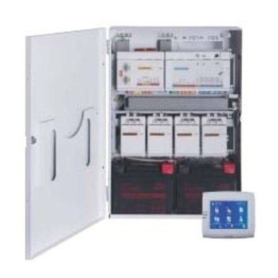
- Page 1 Modular Alarm Platform 5000 ICP‑MAP5000‑2 / ICP‑MAP5000‑COM / ICP‑MAP5000‑S / ICP‑MAP5000‑SC Installation manual...
-
Page 3: Table Of Contents
3.16 Antennas Connections Connecting the Bosch Data Bus 4.1.1 Internal / external Bosch Data Bus 4.1.2 Topology of the external Bosch Data Bus Connecting the power supply 4.2.1 Power supply connections 4.2.2 Optional power supply connections Connecting the MAP5000 panel... - Page 4 | Table of contents Modular Alarm Platform 5000 4.12 IP Interface Initial set-up Programming RPS for MAP 6.1.1 Help for the RPS for MAP 6.1.2 Standard-compliant programming System bundle 6.2.1 Checking the firmware version 6.2.2 Firmware updates 6.2.3 Manufacturer authorization...
-
Page 5: Safety
Security advisories, that is a list of identified vulnerabilities and proposed solutions: https://www.boschsecurity.com/xc/en/support/product-security/security- advisories.html Bosch assumes no liability whatsoever for any damage caused by operating its products with outdated software components. Decommissioning When the system is at the end of service life, remove the connected products from the system and disassemble the system. - Page 6 – Repair & Exchange – Product Security Bosch Building Technologies Academy Visit the Bosch Building Technologies Academy website and have access to training courses, video tutorials and documents: www.boschsecurity.com/xc/en/support/training/ 2024-10 | V26 | F.01U.168.332 Bosch Security Systems B.V. Installation manual...
-
Page 7: Introduction
– Only authorized service personnel is allowed to install this MAP5000 system. – Use only the installation material recommended by BOSCH Security Systems to ensure error-free operation. – Follow anti-static procedures when handling system components. Ensure that you are properly grounded to discharge any static charge before you work with system components. - Page 8 | Introduction Modular Alarm Platform 5000 – MAP5000 panel – ICP-MAP0007-2 MAP DE interface module – ICP-MAP0010 MAP LSN gateway – ICP-MAP0012 MAP BDB/CAN splitter – AT x000 communicator – IPP-MAP0005-2 MAP power supply 150W – ICP-MAP0065 MAP terminal block –...
-
Page 9: Planning The System With Power Supply
Modular Alarm Platform 5000 Introduction | en 2.4.1 Planning the system with power supply Number of power supplies To guarantee a reliable system booting, take into account the following: – Inrush current of the connected loads – Current limit of the IPP-MAP0005-2 MAP power supply 150W –... - Page 10 | Introduction Modular Alarm Platform 5000 Figure 2.1: Wiring of power supply segments Condition 2 Charged batteries must be connected to the power supply to ensure reliable system start- Figure 2.2: Batteries for system booting Condition 3 To ensure reliable system start-up, it is necessary to take into account the cable length and wire gauge: –...
- Page 11 Modular Alarm Platform 5000 Introduction | en Figure 2.3: Wiring with ICP-MAP0111 Callout Description Current limitation 4-wire connection, take into account cable length, refer to Cable length, page 12 3-wire connection to the next power supply segment Short-time current limitation to 3.2 A per output A / B Current limitation to 1.6 A between internal and external BDB...
- Page 12 | Introduction Modular Alarm Platform 5000 Figure 2.5: Up to 8 touch keypads Callout Description Current limitation 4-wire connection, take into account cable length, refer to Cable length, page 12 3-wire connection to the next power supply segment Short-time current limitation to 3.2 A per output A / B...
-
Page 13: Planning The System With Bdb/Can Splitter
Modular Alarm Platform 5000 Introduction | en The following applies for VdS For remote operation of the IPP-MAP0005-2 MAP power supply 150W, a touch keypad assigned to the same area must be provided for indication of power supply trouble (trouble in mains supply / battery). -
Page 14: System Overview
| Introduction Modular Alarm Platform 5000 ICP-MAP0012 MAP BDB/CAN splitter Cable length The cable length of the splitted external BDB depends on the number of added touch keypads and of the cable diameter. The maximum cable length is 500 m per BDB connector. - Page 15 Modular Alarm Platform 5000 Introduction | en System installation in ICP-MAP0111 MAP panel enclosure (hinged mounting plate closed) Callout Description ICP-MAP0007-2 MAP DE interface module ICP-MAP0111 MAP panel enclosure MAP5000 panel ICP-MAP0025 MAP hinged mounting plate ICP-MAP0010 MAP LSN gateway Bosch Security Systems B.V.
- Page 16 | Introduction Modular Alarm Platform 5000 System installation in ICP-MAP0111 MAP panel enclosure (hinged mounting plate open) Callout Description ICP-MAP0111 MAP panel enclosure AT x000 communicator ICP-MAP0050 MAP panel/power enclosure tamper switch ICP-MAP0065 MAP terminal block IPP-MAP0005-2 MAP power supply 150W ICP-MAP0025 MAP hinged mounting plate 2024-10 | V26 | F.01U.168.332...
- Page 17 Modular Alarm Platform 5000 Introduction | en System installation in ICP-MAP0120 MAP expansion enclosure Callout Description IPP-MAP0005-2 MAP power supply 150W ICP-MAP0065 MAP terminal block ICP-MAP0055 MAP expansion enclosure tamper switch ICP-MAP0120 MAP expansion enclosure Bosch Security Systems B.V. 2024-10 | V26 | F.01U.168.332...
- Page 18 | Introduction Modular Alarm Platform 5000 Enclosure overview Callout Description Wire trays Wire knockouts Mounting rails for ICP-MAP0020 MAP accessory mounting plate Mounting location for TAE box Knockout for wall tamper Mounting location for ICP-MAP0065 MAP terminal block Grounding studs...
-
Page 19: Installation
Modular Alarm Platform 5000 Installation | en Installation – Use proper anchor and screw sets when installing the enclosure on surfaces. Refer to the drill template for detailed instructions. – Ensure that there is enough free space to the left of the enclosure so that the enclosure door and the ICP-MAP0025 MAP hinged mounting plate have full range of motion. -
Page 20: Installing The Tamper Switch Rail
| Installation Modular Alarm Platform 5000 Knockout for wall tamper (required in accordance with VdS and EN50131 grade 3) Knockout for TAE box Knockouts for wiring Knockout for AC wires (use when AC wires come in from the back of the... - Page 21 Modular Alarm Platform 5000 Installation | en Mounting the tamper switch rail Callout Description ICP-MAP0111 MAP panel enclosure ICP-MAP0050 MAP panel/power enclosure tamper switch Use the same way as shown above to mount the tamper switch rail for ICP-MAP0055 MAP expansion enclosure tamper switch in the ICP-MAP0120 MAP expansion enclosure.
-
Page 22: Mounting The Enclosure
| Installation Modular Alarm Platform 5000 Mounting the enclosure 3.3.1 MAP panel enclosure Inserting the wall tamper plug Use the supplied drill template to mark the holes on the intended surface. The drill template can be found in the enclosure box. - Page 23 Modular Alarm Platform 5000 Installation | en Mounting the ICP-MAP0111 MAP panel enclosure Callout Description Mounting hole Hole for screw to secure wall tamper plug Mount the enclosure to the intended surface using suitable screws and anchors (not supplied). Use the mounting holes as shown in the figure.
-
Page 24: Map Power Enclosure
| Installation Modular Alarm Platform 5000 3.3.2 MAP power enclosure Connect the ICP-MAP0115 MAP power enclosure to the ICP-MAP0111 MAP panel enclosure to provide additional power when high power capacity is required. ICP-MAP0115 MAP power enclosure with thermistor Callout Description 2024-10 | V26 | F.01U.168.332... -
Page 25: Map Expansion Enclosure
Modular Alarm Platform 5000 Installation | en ICP-MAP0111 MAP panel enclosure ICP-MAP0130 Thermistor cable IPP-MAP0005-2 MAP power supply 150W ICP-MAP0065 MAP terminal block ICP-MAP0115 MAP power enclosure ICP-MAP0050 MAP panel/power enclosure tamper switch Refer to – Installing the thermistor cable, page 28 3.3.3... -
Page 26: Checking The Ac Connection
| Installation Modular Alarm Platform 5000 Checking the AC connection Ensure that the AC circuit breaker switch is off. Connect the AC line to the AC terminal block. Switch the AC breaker on. Verify that the circuit breaker does not trip and that appropriate line voltage is present on the fused side of the AC terminal block. - Page 27 Modular Alarm Platform 5000 Installation | en Installing the power supply Callout Description ICP-MAP0111 MAP panel enclosure IPP-MAP0005-2 MAP power supply 150W Slide the left side of the power supply against the flange on the left side of the enclosure back wall.
-
Page 28: Installing The Ac Terminal Block
| Installation Modular Alarm Platform 5000 Installing the AC terminal block Warning! When installing the power supply, ensure that the ground wire from the MAP terminal block is connected to the grounding stud. The ground wire from the MAP terminal block to the power supply does not provide an earth ground for the enclosure. -
Page 29: Installing The Tae Box
Modular Alarm Platform 5000 Installation | en Notice! In case more than one enclosure is used, mount the thermistor cable in the enclosure in which the power supply is placed. Mounting the thermistor Installing the TAE box If the TAE box is not mounted on the wall behind the enclosure, mount the TAE box to the enclosure back wall either horizontally or vertically as desired. -
Page 30: Installing The Accessory Mounting Plate
| Installation Modular Alarm Platform 5000 ICP-MAP0111 MAP panel enclosure Installing the accessory mounting plate Align the earth ground stud on the accessory mounting plate with the earth ground hole on the top mounting rail in the upper right side of the enclosure wall as shown in the figure below. - Page 31 Modular Alarm Platform 5000 Installation | en Installing the accessory mounting plate Refer to Accessory mounting plate overview, page 31 for the locations of the modules that mount on the accessory mounting plate. Accessory mounting plate overview Callout Description ICP-MAP0111 MAP panel enclosure...
-
Page 32: Installing The Power Converter
| Installation Modular Alarm Platform 5000 Screw location for AT x000 earth ground 3.10 Installing the power converter Mount the ICP-MAP0017 MAP 12V-28V power converter onto the accessory mounting plate as shown in the figure below (screws not supplied). -
Page 33: Installing The At X000 Communicator
Modular Alarm Platform 5000 Installation | en Installing the SIV 28 fuse plate Callout Description ICP-MAP0020 Accessory mounting plate SIV 28 fuse plate (SIV 28 MAP 28V fuse protected power distributer) 3.12 Installing the AT x000 communicator The AT x000 communicator mounts onto the ICP-MAP0020 MAP accessory mounting plate over the power converter (if installed). - Page 34 | Installation Modular Alarm Platform 5000 Installing the AT x000 communicator Callout Description ICP-MAP0020 MAP accessory mounting plate AT x000 communicator Connect the AT x000 communicator to the ICP-MAP0007-2 MAP interface DE module using the supplied ICP-MAP0154 MAP ribbon cable.
- Page 35 Modular Alarm Platform 5000 Installation | en Analog AT x000 to DE module connections Callout Description AT x000 communicator ICP-MAP0007-2 MAP DE interface module Notice! The two trouble inputs are automatically configured to "Communicator Trouble" and "Negative Acknowledgment" when "Communicator" is selected in the Remote Programming Software for MAP (RPS for MAP).
-
Page 36: Installing The Hinged Mounting Plate
| Installation Modular Alarm Platform 5000 Analog AT x000 to the power converter connections Callout Description IPP-MAP0005-2 MAP power supply 150W ICP-MAP0017 12 MAP 12V-28V power converter AT x000 communicator 3.13 Installing the hinged mounting plate Install the ICP-MAP0025 hinged mounting plate inside the enclosure ICP-MAP0111 or ICP-MAP0120. -
Page 37: Mounting The Modules Onto The Hinged Mounting Plate
Modular Alarm Platform 5000 Installation | en Installing the hinged mounting plate Callout Description ICP-MAP0111 MAP panel enclosure ICP-MAP0025 MAP hinged mounting plate 3.13.1 Mounting the modules onto the hinged mounting plate Hinged mounting plate overview The following graphic shows an overview of the hinged mounting plate and the designated mounting locations of the modules. - Page 38 | Installation Modular Alarm Platform 5000 Callout Description ICP-MAP0007-2 MAP DE interface module ICP-MAP0010 MAP LSN gateway ICP-MAP0012 MAP BDB/CAN splitter MAP5000 panel ICP-MAP0025 MAP hinged mounting plate Sliding the module onto the hinged mounting plate Slide the module onto the hinged mounting plate.
- Page 39 Modular Alarm Platform 5000 Installation | en Connecting the grounding cable to the hinged mounting plate Connect the grounding cable from the enclosure back wall to the hinged mounting plate. Bosch Security Systems B.V. 2024-10 | V26 | F.01U.168.332 Installation manual...
-
Page 40: Mounting The Map5000 Panel On The Hinged Mounting Plate
| Installation Modular Alarm Platform 5000 3.13.2 Mounting the MAP5000 panel on the hinged mounting plate How to mount the MAP5000 panel The MAP5000 panel is mounted on the hinged mounting plate. For information on how to mount modules on the hinged mounting plate, refer to Mounting the modules onto the hinged mounting plate, page 37. -
Page 41: Installing And Connecting The Supported Gsm Modem
Modular Alarm Platform 5000 Installation | en Installing the ICP-COM-IF2 relay module 3.15 Installing and connecting the supported GSM modem The ITS-MAP0008 wireless modem is used for wireless transmission of data via GSM/GPRS. The wireless modem can only be used when one of the following MAP5000 panels is installed: –... - Page 42 | Installation Modular Alarm Platform 5000 Warning! In order to avoid data loss on the SIM card, the wireless modem must be de-energized before inserting or removing the SIM card. Installing and connecting the wireless modem Callout Description ITS-MAP0008 wireless modem...
-
Page 43: Antennas
Modular Alarm Platform 5000 Installation | en LED mode Operating status of M terminal – No SIM card inserted – No PIN entered – Network search in progress – Ongoing user authentication – Network login in progress 75 ms on, 3 s off Idle mode: The mobile is logged to the network (monitoring control channels and user interactions). - Page 44 | Installation Modular Alarm Platform 5000 Transmission frequency: 900 / 1800 MHz Impedance: 50 Ω Gain: 3.5 dBi (without cable) Max. power: 20 W Radiator length: 250 mm Distance radiator-installation surface: 150 Area of use: inside, outside Rod antenna incl. 20 m cable.
-
Page 45: Connections
Modular Alarm Platform 5000 Connections | en Connections Caution! Wiring Pinching of the wires is possible due to incorrectly hinged components. – Ensure that there is sufficient slack in the service wire loop to allow proper movement of the hinged mounting plates. - Page 46 | Connections Modular Alarm Platform 5000 Internal BDB connections Callout Description MAP5000 panel ICP-MAP0007-2 MAP DE interface module ICP-MAP0146 Panel power cable ICP-MAP0132 Data bus cable, long ICP-MAP0010 LSN gateway or ICP-MAP0012 MAP BDB/CAN splitter IPP-MAP0005-2 MAP power supply 150W...
-
Page 47: Internal / External Bosch Data Bus
Bosch Data Bus cable routing 4.1.1 Internal / external Bosch Data Bus The MAP5000 system contains two Bosch Data Buses (BDB), which are used to connect the system modules to the MAP5000 panel. Internal BDB The maximum length of the internal BDB is 3 m. -
Page 48: Topology Of The External Bosch Data Bus
The following applies for VdS: Touch keypads for different areas must not be connected on the same BDB. 4.1.2 Topology of the external Bosch Data Bus Mount the external BDB as shown below. Notice! Any other bus topology does not conform to the specifications of the BDB. -
Page 49: Optional Power Supply Connections
Input for tamper switch, is activated by configuration for remote operation of the power supply on the external BDB. Output for voltage supply (switched), supervised, nominal voltage 24 VDC Bosch Data Bus - connection A Bosch Data Bus - connection B Output for AC fail and summary power supply trouble (optional) AC connection 4.2.2... -
Page 50: Connecting The Map5000 Panel
| Connections Modular Alarm Platform 5000 Optional power supply connections Connection Description Output for ICP-MAP0017 MAP 12V-28V power converter Output for AC fail and summary power supply trouble (optional) Connecting the MAP5000 panel This chapter describes the connection of the MAP5000 panels. -
Page 51: Connecting De Module
External BDB connector (1) Use this connection to connect additional system modules to the external BDB (refer to Connecting the Bosch Data Bus, page 45 and Modules on the BDB, page 47). Programmable output (2) Use these connections to control devices in certain system states (refer to Programmable output signals, page 67). -
Page 52: Connecting The Lsn Gateway
| Connections Modular Alarm Platform 5000 Outputs (open-collector) COM2 RS232 interface COM1 RS232 interface S1 Parallel interface (Ribbon Cable Connector) Connecting the LSN gateway Notice! When connecting an LSN component, ensure that you follow local standards and guidelines when planning the system installation. - Page 53 Modular Alarm Platform 5000 Connections | en LSN gateway loop configuration LSN Device LSN Device Bosch Security Systems B.V. 2024-10 | V26 | F.01U.168.332 Installation manual...
-
Page 54: Splitting The External Bdb With A Bdb/Can Splitter
| Connections Modular Alarm Platform 5000 LSN gateway stub configuration LSN Device LSN Device Callout Description ICP-MAP0010 MAP LSN gateway ICP-MAP0111 MAP panel enclosure Splitting the external BDB with a BDB/CAN splitter The external BDB can be splitted into two independent and isolated stubs to connect touch keypads, gateways and further power supplies. -
Page 55: Connecting The Touch Keypad
Modular Alarm Platform 5000 Connections | en BDB/CAN splitter wiring without consideration of the power supply Max. 500 m Max. 500 m Callout Description ICP-MAP0012 BDB/CAN splitter Refer to – Planning the system with BDB/CAN splitter, page 13 Connecting the touch keypad The BDB supports up to 32 touch keypads. -
Page 56: Installing The Touch Keypad
| Connections Modular Alarm Platform 5000 External BDB connection of the touch keypad 120 Ω R Y G B R Y G B Callout Description MAP touch keypad MAP5000 panel External BDB Installing the touch keypad Mounting location Mount the touch keypad onto the wall so that the user interface is at a comfortable level for the end user. -
Page 57: Installing And Connecting The Tamper Switch
Modular Alarm Platform 5000 Connections | en Opening the touch keypad Installing and connecting the tamper switch – Install the ICP-MAP0050 MAP panel/power enclosure tamper switch in the ICP- MAP0111 MAP panel enclosure. – Install the ICP-MAP0055 MAP expansion enclosure tamper switch in the ICP-MAP0120 MAP expansion enclosure. - Page 58 | Connections Modular Alarm Platform 5000 ICP-MAP0055 MAP expansion enclosure tamper switch Slide the tamper switch onto the rail as shown in the figure below. Mounting the tamper switch onto the rail Clip off the connector from the cable of the tamper switch.
- Page 59 Modular Alarm Platform 5000 Connections | en Connecting the ICP-MAP0050 tamper switch Callout Description MAP5000 panel MAP panel/power enclosure tamper switch Bosch Security Systems B.V. 2024-10 | V26 | F.01U.168.332 Installation manual...
-
Page 60: Installing The Icp-Map0060 Map Enclosure Lockset
| Connections Modular Alarm Platform 5000 Connecting the ICP-MAP0055 tamper switch Callout Description MAP5000 panel ICP-MAP0055 MAP expansion enclosure tamper switch Notice! When the enclosure door is opened, the tamper switch creates a tamper condition. To allow for a local connection between RPS for MAP and the MAP5000 panel, connect the tamper switch to the MAP5000 panel and not the power supply. -
Page 61: Final Power Connections
Modular Alarm Platform 5000 Connections | en Installing the enclosure lockset Connecting the grounding cable to the enclosure door 4.11 Final power connections Make sure that the AC wires are connected to the MAP terminal block. Connect the battery wire leads to the batteries. -
Page 62: Ip Interface
| Connections Modular Alarm Platform 5000 Ensure that there are no power-related trouble conditions. Warning! Ensure that the AC LED indicator on the power supply turns on steady before you connect the battery terminal to the power supply. Warning! Remove the protective dust cover label from the top of the power supply. - Page 63 Modular Alarm Platform 5000 Connections | en In the MAP5000 panel menu, select -> setup: Management system as a Monitoring Station. Notice! Data transfer between the MAP5000 and the connected PC system must always take place via a secure, authenticated and encrypted connection.
-
Page 64: Initial Set-Up
| Initial set-up Modular Alarm Platform 5000 Initial set-up First check the following before initial set-up: – Are all cables connected correctly? – The power supply is always in operation after the AC mains has been connected and the AC breaker switched on. -
Page 65: Programming
Modular Alarm Platform 5000 Programming | en Programming Programming is performed with Remote Programming Software for MAP (RPS for MAP). A PC or laptop with compatible Windows operating system is required for this. At least 256 MB RAM is needed. A mouse is recommended for operation of the program. -
Page 66: System Bundle
| Programming Modular Alarm Platform 5000 Select Restore all properties using <selected standard> default property values set. Confirm with Yes. Compliance check / validation During programming, you can check whether programming is compliant with the selected standard at any time. -
Page 67: Point Types And Point Evaluation
Modular Alarm Platform 5000 Programming | en Systems in accordance with VdS class C and EN 50131 On systems in accordance with VdS class C and EN 50131, screw the door closed on the lock side with two sheet-metal screws (3.5 mm x 10 mm) from the accessory pack in order to guarantee sufficient mechanical strength. - Page 68 | Programming Modular Alarm Platform 5000 Behavior item type Output is activated for … Technical alarm Technical alarm External system trouble Power supply failure (p), battery trouble Internal system trouble Power supply failure, ground fault, printer trouble External intrusion trouble...
- Page 69 Modular Alarm Platform 5000 Programming | en Behavior item type Output is activated for … External tamper alarm Tamper alarm from armed area Bypass At least one device is bypassed Disable At least one device is disabled Management system interface...
-
Page 70: Sirens And Communicator In Accordance With En50131 Grade 3
| Programming Modular Alarm Platform 5000 Behavior item type Output is activated for … External tamper alarm Tamper alarm from disarmed area with simultaneous disarmed reporting via the communicator Transmission path fault In the event of communication failure between... - Page 71 Modular Alarm Platform 5000 Programming | en Variant D (ICP-COM-IF2 required) – One communicator (min. SP4) Outputs R1 - R7 on ICP-COM-IF2 Bosch Security Systems B.V. 2024-10 | V26 | F.01U.168.332 Installation manual...
-
Page 72: Maintenance And Service
Notice! Have maintenance and inspection work carried out regularly by trained expert personnel. Bosch Sicherheitssysteme GmbH recommends performing a functional and visual inspection at least once annually. Danger! Danger of electric shock if live parts are touched. For your safety, you should switch off the... - Page 73 Modular Alarm Platform 5000 Maintenance and service | en The operating LED starts blinking slowly to indicate the installer mode. ð Switching off the installer mode Press the installer button on the MAP5000 panel for three seconds. System restart The system can be restarted without being de-energized.
-
Page 74: Technical Specifications
| Technical Specifications Modular Alarm Platform 5000 Technical Specifications Electrical Maximum operating voltage in VAC 230 (-15 %, + 10%) Minimum AC line frequency in Hz Maximum AC line frequency in Hz Maximum power consumption in W per power supply... - Page 75 MAP power supplies 150W MAP BDB/CAN splitters Ethernet interface 1, RJ 45 connection, 100Mbps maximum Management system connection Via MAP OPC server from Bosch - in VdS systems, only feedback-free connection as information system via exclusive transmission path Number of inputs...
- Page 76 | Technical Specifications Modular Alarm Platform 5000 Maximum storage temperature in °C Minimum relative humidity in % Maximum relative humidity in % Protection class IP30 Security level IK06 Environmental class EN50130-5, EN50131-1, VdS 2110, VdS 2252 Usage Indoor 2024-10 | V26 | F.01U.168.332 Bosch Security Systems B.V.
-
Page 77: Appendices
Modular Alarm Platform 5000 Appendices | en Appendices This chapter contains information and instructions for creating programming that complies with the requirements of a specific standard. Notice! Use the default setting for parameters that are not explicitly mentioned in this description. - Page 78 | Appendices Modular Alarm Platform 5000 Open MAP panel enclosure. authorize from RPS for MAP with an AE 2 user with corresponding permissions (touch keypad: main menu page 2 > RPS). Establish a connection between the MAP5000 panel and RPS for MAP.
- Page 79 Modular Alarm Platform 5000 Appendices | en May clear external alarm May clear tamper May clear trouble May clear battery trouble May silence Remote service category permissions May authorize manufacturer user May authorize RPS for MAP user Arm category permissions...
-
Page 80: Connection Of An Lsn Fire Detector As A Technical Detector
| Appendices Modular Alarm Platform 5000 May walk test points Table 9.2: Permissions * also with Duress PIN 9.1.7 Connection of an LSN fire detector as a technical detector Warning! Configuration The configuration of an LSN fire detector may not impact the arming function. -
Page 81: Arming / Disarming With Entry / Exit Delay
Modular Alarm Platform 5000 Appendices | en Select the area in the properties field of the Key Switch > Area. In the properties field of the Touch Keypad, include the area in the scope Local Area or Additional Areas in Scope Programming two outputs for signaling the armed / disarmed state Connect one free output in each case with the device LED. -
Page 82: Forced Arming With Automatic Bypass
| Appendices Modular Alarm Platform 5000 Interrupt Door point that shortens the running exit delay to 10 sec. (recommended) Restart Point that restarts the exit delay; possible only once during the exit Table 9.3: Exit point types Not for EN 50131 Select the type of entry point for all entry route points. -
Page 83: Alarm Output Via Siren And Communicator
Modular Alarm Platform 5000 Appendices | en Programming two outputs for signaling the armed / disarmed state Connect one free output in each case with the device LED. Using the wizard, program one output with the behavior item Area Armed and a second output with the behavior item Area Disarmed. -
Page 84: Connection To A Management System
| Appendices Modular Alarm Platform 5000 9.2.8 Connection to a management system Refer to IP Interface, page 62. 9.2.9 Printer connection Connecting the supported printer is permitted only for service purposes. 9.2.10 Access levels The standard distinguishes between four access levels (AE): –... - Page 85 Modular Alarm Platform 5000 Appendices | en In the properties> behavior item list of the device siren, activate the option Include External Tamper Alarm Disarmed of Onboard Tamper. Functions of the access levels The assignment of the functions to the access levels 2 and 3 can be adapted in RPS for MAP.
-
Page 86: Additional Functions
| Appendices Modular Alarm Platform 5000 May arm area * May disarm area * Can disarm only if in alarm May bypass detectors May bypass detectors in area May unbypass detector May switch internal program on/off Status category permissions... -
Page 87: Requirements In Accordance With Ses
Modular Alarm Platform 5000 Appendices | en Internal program Points of the point type Intrusion can be assigned to an internal program. When points are assigned to an internal program, and internal program is switched on, the points are capable of alarm signaling in disarmed state. -
Page 88: Areas With Blocking Time
| Appendices Modular Alarm Platform 5000 Optionally program automatic bypassing of points. Automatic arming at a predefined time without warning signal – Start the schedule wizard and define the time of arming. – As action, select Arm Area(s) Immediately. - Page 89 Modular Alarm Platform 5000 Appendices | en Open MAP panel enclosure. Internal warning device is activated for 3 sec. authorize from RPS with an AE 2 user with corresponding permissions (touch keypad: main menu page 2 > RPS). Establish a connection between the MAP5000 panel and RPS for MAP.
- Page 90 | Appendices Modular Alarm Platform 5000 May turn chime on/off May change schedule May edit blocking time User category permissions May add user May delete user May change user passcode Event category permissions May clear internal alarm May clear external alarm...
-
Page 91: Tamper Surveillance
Modular Alarm Platform 5000 Appendices | en Maintenance category permissions May adjust touch keypad volume/brightness May change output state May set date time May test bell May test motion detectors May walk test automatic points May walk test points Table 9.6: SES Permissions... -
Page 92: Alarm Reporting
| Appendices Modular Alarm Platform 5000 Class 1 Demand-driven connection with 25-hourly function monitoring and voice annunciation AÜA-B25 Class 2 Demand-driven connection with 25-hourly function monitoring and simple digital transmission Class 3 Demand-driven connection with 25-hourly function monitoring and digital transmission Class 4 AÜA-B5... - Page 93 Modular Alarm Platform 5000 Appendices | en Both history logs are independent from each other and cannot influence each other. In both history logs, the logged mandatory events cannot be deleted or overwritten by any logged optional events. For both history logs there is no duration defined. This means, that events are stored for an unlimited amount of time and are not affected in case of power loss at the MAP5000 panel.
- Page 94 | Appendices Modular Alarm Platform 5000 2024-10 | V26 | F.01U.168.332 Bosch Security Systems B.V. Installation manual...
- Page 96 Bosch Security Systems B.V. Torenallee 49 5617 BA Eindhoven Netherlands www.boschsecurity.com © Bosch Security Systems B.V., 2024 Building solutions for a better life 202410240458...
Need help?
Do you have a question about the Modular Alarm Platform 5000 and is the answer not in the manual?
Questions and answers