Table of Contents
Advertisement
Quick Links
Advertisement
Table of Contents

Related Manuals for Bosch AEC‑AMC2‑UL01


Summary of Contents for Bosch AEC‑AMC2‑UL01
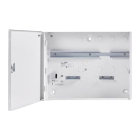
- Page 1 AMC2 enclosure with 1 DIN rail AEC‑AMC2‑UL01 Installation manual...
-
Page 3: Table Of Contents
Mounting the enclosure Connections Connecting the devices Connecting the cables Connections for supporting Universal Power Supply 12 V mode operation 3.3.1 24 V mode operation 3.3.2 Appendices UL requirements Cable assembly Bosch Security Systems B.V. 2020-07 | V04 | F.01U.330.018... -
Page 4: System Overview
Mounting rail for power supply unit (PSU) and Access Modular Controller (AMC2) AMC2 grounding point Cable knock-outs for reader and signal cables Temperature sensor bracket Tamper contact Fixing bracket for rechargeable batteries Main grounding point 2020-07 | V04 | F.01U.330.018 Bosch Security Systems B.V. - Page 5 AMC2 enclosure with 1 System overview | en DIN rail Position Description Label Knock-out for the power cable connection Three pin connector Bracket for LED Name plate Bosch Security Systems B.V. 2020-07 | V04 | F.01U.330.018...
-
Page 6: Parts Included
AMC2 enclosure with 1 en | System overview DIN rail Parts included 2020-07 | V04 | F.01U.330.018 Bosch Security Systems B.V. - Page 7 System overview | en DIN rail Position Description Cable ties to secure cables Three screw anchors S8 and M6 × 50 screws Bracket for cable fixing Fuse and fuse holder Cover grounding cable Bosch Security Systems B.V. 2020-07 | V04 | F.01U.330.018...
-
Page 8: Cables To Be Assembled
AMC2 enclosure with 1 en | System overview DIN rail Cables to be assembled Position Description Power supply cable (AMC2) Power supply cable (battery) Battery cable Cover contact wired Power cable 2020-07 | V04 | F.01U.330.018 Bosch Security Systems B.V. - Page 9 AMC2 enclosure with 1 System overview | en DIN rail Position Description Power cable with LED indicator (UL required) Refer to – Cable assembly, page 21 Bosch Security Systems B.V. 2020-07 | V04 | F.01U.330.018...
-
Page 10: Mounting The Enclosure
7,894 in 5 mm 0,197 in 10 mm 0,394 in 318 mm 12,52 in 5 mm 0,197 in 10 mm 0,394 in 352,5 mm 13,878 in Figure 2.1: Dimensions of the enclosure 2020-07 | V04 | F.01U.330.018 Bosch Security Systems B.V. -
Page 11: Connections
Provide an appropriate disconnect device to the supply line. Warning! Risk of electric shock! Disconnect the mains supply voltage before you work on the devices inside the enclosure. Bosch Security Systems B.V. 2020-07 | V04 | F.01U.330.018... - Page 12 Mount the power supply unit on the left-hand side of the mounting rail. If you are using rechargeable batteries, install the batteries at the bottom of the enclosure and secure them with a fixing bracket. 2020-07 | V04 | F.01U.330.018 Bosch Security Systems B.V.
-
Page 13: Connecting The Cables
Connect the blue wire to the port marked with N (Figure 3.2, positions 2 and 4). Connect the brown wire to the port marked with L (Figure 3.2, positions 1 and 3). Figure 3.2: Connections of the LED indicator Bosch Security Systems B.V. 2020-07 | V04 | F.01U.330.018... - Page 14 (marked with T) at the top of the AMC2. Position the cable in the space between the housing and the mounting rail. Danger! Risk of electric shock Make sure that all wires have zero potential. 2020-07 | V04 | F.01U.330.018 Bosch Security Systems B.V.
-
Page 15: Connections For Supporting Universal Power Supply
Connections for supporting Universal Power Supply Precondition: Before switching to battery operation, disconnect the AC power cable. Notice! Use 12 V 7 (7,2) Ah lead batteries only. Notice! Change the lead batteries every 5 years. Bosch Security Systems B.V. 2020-07 | V04 | F.01U.330.018... -
Page 16: 12 V Mode Operation
Connect B7a (red) to the rechargeable positive (+) terminal of the battery. Attach the bracket to the back of the housing next to the batteries. Attach the connectors B8a and B8b to the bracket. 2020-07 | V04 | F.01U.330.018 Bosch Security Systems B.V. - Page 17 Connect B7a (red) to the rechargeable positive (+) terminal of the battery. Connect B8b (black) to the second rechargeable negative (-) terminal. Connect B8a (red) to the second rechargeable positive (+) terminal of the battery. Bosch Security Systems B.V. 2020-07 | V04 | F.01U.330.018...
-
Page 18: Mode Operation
With cable C1 (black), connect the negative (-) pin of the first rechargeable battery to the positive (+) pin of the second rechargeable battery. Attach the connectors B8a and B8b to the bracket. 2020-07 | V04 | F.01U.330.018 Bosch Security Systems B.V. - Page 19 AMC2 enclosure with 1 Connections | en DIN rail Attach the bracket to the back of the housing next to the batteries. Bosch Security Systems B.V. 2020-07 | V04 | F.01U.330.018...
-
Page 20: Appendices
If the system is to be UL294 compliant, make sure that all the cables and the respective parts are UL listed or approved. Notice! All supplier examples given in chapter Cable assembly, page 21 are UL authorized. 2020-07 | V04 | F.01U.330.018 Bosch Security Systems B.V. -
Page 21: Cable Assembly
1015 121180 07 Wire 18 MediKabel UL Style AWG GN/ 1015 121180 49 Wire 18 MediKabel UL Style AWG blue 1015 121180 06 End splice Klauke - 172RK insulated red 1,5 Bosch Security Systems B.V. 2020-07 | V04 | F.01U.330.018... - Page 22 DIN rail Position Description Quantity Size Supplier example Ring Klauke - 6204 terminal red 4-1 Power connector of AMC2 Power supply control connector 4 pin Power supply DC connector Grounding cable 2020-07 | V04 | F.01U.330.018 Bosch Security Systems B.V.
- Page 23 1,5 Non- Klauke - 18203 insulated TYCO - 5-160430-7 receptacle 4,8-1 Non- Klauke - 18303 insulated TYCO - 5-160429-2 receptacle 4,8-2,5 Conduit Stocko - EH sleeve 4,8 650.110.PA66 Bosch Security Systems B.V. 2020-07 | V04 | F.01U.330.018...
- Page 24 C - Battery cable Figure 4.2: Battery cable Position Description Quantity Size Supplier example Wire 18 MediKabel UL Style AWG blue 1015 121180 06 Non- Klauke - 18203 insulated TYCO - 5-160430-7 receptacle 4,8-1 2020-07 | V04 | F.01U.330.018 Bosch Security Systems B.V.
- Page 25 Position Description Quantity Size Supplier example Wire 22 MediKabel UL Style AWG black 1007 120227 08 End splice Klauke - 169OK orange 0,5 Micro Saia-Burgess - switch V4NST7Y1UL E - Power cable Bosch Security Systems B.V. 2020-07 | V04 | F.01U.330.018...
- Page 26 MediKabel UL Style AWG blue 1015 121180 06 Wire 18 MediKabel UL Style 1015 121180 01 brown End splice Klauke - 172RK insulated red 1,5 Power supply AC connector Enclosure Power connector 2020-07 | V04 | F.01U.330.018 Bosch Security Systems B.V.
- Page 27 MediKabel UL Style 1015 121180 01 brown End splice Klauke - 172RK insulated red 1,5 Twin cable Klauke - 8708 end sleeve grey 2 x 0,75 Bulgin - 2950MG9 indicator 125-250V green Bosch Security Systems B.V. 2020-07 | V04 | F.01U.330.018...
- Page 28 AMC2 enclosure with 1 | Appendices DIN rail 2020-07 | V04 | F.01U.330.018 Bosch Security Systems B.V.
- Page 29 AMC2 enclosure with 1 Appendices | DIN rail Bosch Security Systems B.V. 2020-07 | V04 | F.01U.330.018...
- Page 30 AMC2 enclosure with 1 | Appendices DIN rail 2020-07 | V04 | F.01U.330.018 Bosch Security Systems B.V.
- Page 32 Bosch Security Systems B.V. Torenallee 49 5617 BA Eindhoven Netherlands www.boschsecurity.com © Bosch Security Systems B.V., 2020...
Need help?
Do you have a question about the AEC‑AMC2‑UL01 and is the answer not in the manual?
Questions and answers