
Subscribe to Our Youtube Channel
Related Manuals for RMG USM GT400


Summary of Contents for RMG USM GT400
- Page 1 Operating Manual Ultrasonic Flowmeter USM GT400 Issued: 07.05.2021 Version: Firmware:...
- Page 2 +49 6033 897 – 130 E-Mail service@rmg.com Original Document The Ultrasonic Flowmeter USM GT400 OPERATING INSTRUCTION 07.05.2021 is the original document. This document may serve as a reference for translations into other languages. Please use in case of any uncertainties the German version as main reference.
-
Page 3: Table Of Contents
Parameter setting ....................24 3 DEVICE OVERVIEW ................25 Main components ....................25 Ultrasonic electronics ..................27 Arrangement of the ultrasonic transducers ..........31 4 FUNCTIONAL PRINCIPLE – ULTRASONIC-FLOW MEASUREMENT .................. 32 Manual USM GT400 · EN10 · May 2021... - Page 4 Data input via RMGBus ..................45 4.4.4 Data via Modbus (USM GT400 is SLAVE) ............46 4.4.5 Import of data via Modbus (USM GT400 is Master).......... 47 Batch mode ......................52 Signal damping ....................52 5 SAFETY....................53 Intended use ......................54 Layout of instructions ..................
- Page 5 Installing the pressure connection .............. 128 Outdoor installation ..................130 9 START UP ................... 132 Comparing meter parameters ............... 132 Checking functions of the USM ..............132 Reading out speed of sound ................. 133 Manual USM GT400 · EN10 · May 2021...
- Page 6 Cleaning the device ..................167 11.7 Check the official seal .................. 168 11.8 Decommissioning and disposal ..............168 11.9 12 ALARM AND WARNING MESSAGES ........... 170 Alarm messages .................... 171 12.1 Warning messages ..................172 12.2 Manual USM GT400 · EN10 · May 2021...
- Page 7 Pressure devices approval ................. 246 16.2 Electromagnetic compatibility ..............246 16.3 Explosion protection approval ..............246 16.4 Standards, directives and guidelines ............247 16.5 17 USM GT400 GLOSSARY ..............249 18 USM GT400 ATTACHMENT ............. 250 Manual USM GT400 · EN10 · May 2021...
- Page 8 Contents Manual USM GT400 · EN10 · May 2021...
-
Page 9: About This Manual
For this reason, you may only use the device as intended and in technically sound condition. If the ultrasonic gas meter is not used for its intended purpose, warranty claims will be void. Manual USM GT400 · EN10 · May 2021... -
Page 10: Specialized Knowledge Required
This manual provides information that is necessary for fault-free and safe opera- tion. The Ultrasonic Flowmeter USM GT400 was designed and produced according to the state of the art and generally recognized safety standards and directives. How- ever, its use can entail dangers that are avoidable by complying with this manual. -
Page 11: Abbreviations
Measurement Canada Measurement Instruments Directive min. minimum Signal to Noise Ratio Speed of Sound Transducer (ultrasonic transmitter and receiver) Transducer of a certain production type. Ultrasonic electronics Ultrasonic gas meter e.g. For example Manual USM GT400 · EN10 · May 2021... -
Page 12: Layout Of Instructions
This notice provides you with helpful tips to make your work easier. This notice also provides you with further information about the device or the work process in order to prevent operator error. Manual USM GT400 · EN10 · May 2021... -
Page 13: Working With The Device
Use of the gas chromatograph PGC 9300 is only permitted in accordance with the specifications in the operating manual. RMG assumes no liability for damages arising due to disregard of the op- erating manual. Manual USM GT400 · EN10 · May 2021... - Page 14 As far as possible, all sharp edges on the device have been removed. Nev- ertheless, personal protective equipment must be used for all work, which must be provided by the operator. Manual USM GT400 · EN10 · May 2021...
- Page 15 / education in accordance with DIN VDE 0105, IEC 364 or comparable stand- ards. Danger Connection of pressurized pipelines must only be carried out by trained qualified personnel. Manual USM GT400 · EN10 · May 2021...
- Page 16 1 About this manual Danger The installation and removal of the USM GT400 may only take place in a depressurized state and in an explosion-free atmosphere. During the in- stallation process, the descriptions in the operating instructions must be observed.
- Page 17 Only clean the device as specified in the operating manual. If you do not use the appropriate tool, components may be damaged. The explosion protection becomes invalid. • Only clean the device with a slightly damp cloth! Manual USM GT400 · EN10 · May 2021...
- Page 18 Danger The USM GT400 must only be used as intended! (Chapter 5.1). Danger Prevent use of the USM GT400 as a potential climbing aid or use of attach- ments of the USM GT400 as potential handles. 1.2.4.4 Qualifikation of the user...
-
Page 19: Risk Assessment And Minimization
1.2.5 Risk assessment and minimization According to assessment by qualified employees of RMG, the USM GT 400 is subject to risks during its use. Risks can also arise due to high pressures and oc- casionally due to pressures that are too low. Work outside of the permissible tem- perature range can also lead to dangers. - Page 20 It is essential that these persons are able to recog- nize and avoid potential dangers in good time. Manual USM GT400 · EN10 · May 2021...
-
Page 21: Validity Of The Manual
Validity of the manual This manual describes the Ultrasonic Flowmeter USM GT400. The Ultrasonic Flowmeter USM GT400 is only part of a complete system. The manuals of the other components of the system must be observed, too. If you find contradictory instructions, contact RMG and/or the manufacturers of the other components. -
Page 22: Transport
The following applies in particular to transport: • Shocks and vibrations are to be avoided • Protect the USM GT400 from moisture • If you suspect improper transport or damage during transport, please contact RMG's service department immediately Manual USM GT400 · EN10 · May 2021... - Page 23 Residue from this film changes the flow and causes measuring errors! This protection must be re-applied to the flanges for transport or storage of the device. Manual USM GT400 · EN10 · May 2021...
-
Page 24: Scope Of Delivery
Avoid extended periods of storage. After storage, inspect the device for damage and test for correct function. Contact the RMG service department to arrange for inspection of the device after a storage period of longer than one year. For this purpose, return the device to RMG. -
Page 25: Explosion-Proof Design
1.3 Explosion-proof design 1.3.1 General information Danger The USM GT400 is permitted for installation in explosion-prone areas in Zone 1 that are endangered by gas and vapor assigned to explosion group IIB+H and tempera- ture class T6. ATEX – Zulassungsnummer: BVS 14 ATEX E 034 X... -
Page 26: Inspection And Maintenance Work
In special cases, work can also be carried out on live electrical equipment in haz- ardous areas if it is ensured that no potentially explosive atmosphere is present. This may only be done with explosion-proof, approved measuring instruments. Manual USM GT400 · EN10 · May 2021... - Page 27 (section 1.2.4.4 Qualifikation ). If repairs are carried out by RMG service, no acceptance by an expert is required. Manual USM GT400 · EN10 · May 2021...
-
Page 28: Quick Guide
RMG rejects liability for any damage to the device or other connected de- vices if a user disregards even one of the safety notices in the overall manual because of this chapter “Quick guide”. -
Page 29: Mechanical Connection
Push the pipe into the clamping screw connection until the stop. Tighten the union nut in order to fix and seal the pipe. ◼ Establish connection with the female thread. Unscrew the blind plug. Seal the connection in the thread. Manual USM GT400 · EN10 · May 2021... -
Page 30: Electrical Connection
The USM-GT-400 is supplied without connection box to the North American region, the connection is made to cables that are led through a flame arrester. The marking of the cable (numbers) is (always) identical to the terminal as- signment. Manual USM GT400 · EN10 · May 2021... -
Page 31: Earthing
3 Earthing cable Fig. 2.3: Earthing – Ultrasonic gas meters ≥ DN200 (8”) 13 Connect the earthing cable according to the ultrasonic gas meter version DN100 (4") to DN150 (6") or from DN200 (8"). Manual USM GT400 · EN10 · May 2021... -
Page 32: Parameter Setting
Changes to the pre-assembly are more extensive and are therefore not described in this brief instruction. If this should be necessary, you will then find the descrip- tion: Section 10.1.3, “Calibration and Service Switch” on page 136 Manual USM GT400 · EN10 · May 2021... -
Page 33: Device Overview
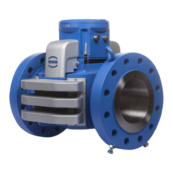
1 Covers of the transducer and transducer lines 2 Covers of the transducer 3 Ultrasonic electronics 4 Lifting eyes 5 Joining flanges 6 Transducer 7 Retaining bolts Fig. 3.1: Main components of the ultrasonic gas meter Manual USM GT400 · EN10 · May 2021... - Page 34 The retaining bolts are mounted when delivering the device. The retaining bolts secure the product from tipping over or rolling away. The bolts must be mounted to ensure for a safe installation or de-installation. Manual USM GT400 · EN10 · May 2021...
-
Page 35: Ultrasonic Electronics
RMGViewUSM software. Service and calibration switch (1) The service switch (right switch) is only for RMG service. The service switch is, e.g., used to install new firmware. The calibration switch (left switch) protects the parameters against unauthorized changes. - Page 36 The calibration switch is open. The value of the parameter can be changed. The calibration switch is closed. The value of the parameter cannot be changed. Forth line Shows the warning, alarm and status messages, e.g., -01 power failure. Manual USM GT400 · EN10 · May 2021...
- Page 37 When holding for a longer time, you can change the lines with quick return. Enter values. Reset button The reset button (1) is for RMG service only. If the reset button is pressed, the ultrasonic electronics is restarted. Switches Calibration switch: Activate to change parameters.
- Page 38 Alarm message is Alarm stored. Warning message is Warning is active. Warning stored. Reset is running. Reset Calibration switch is Calibration open. Service switch is open. Service Control panel Panel is being pressed. Manual USM GT400 · EN10 · May 2021...
-
Page 39: Arrangement Of The Ultrasonic Transducers
The arrangement of the transducers in the three levels is shown in three section representations. Four transducers are installed per level. The transducers form two paths per level for the measurement. Manual USM GT400 · EN10 · May 2021... -
Page 40: Functional Principle - Ultrasonic-Flow Measurement
Data input on fixed defaults for air 4.4.3 Data input via RMGBus 4.4.4 Data via Modbus (USM GT400 is SLAVE) 4.4.5 Import of data via Modbus (USM GT400 is Master) 4.54.5 Batch modeBatch mode Manual USM GT400 · EN10 · May 2021... -
Page 41: General Description
�� �� ����12 ����21 �� �� − �� �� ���� ����21 ����12 ��̅ = ∙ ∙ 2 ∙ �� �� ∙ �� 2 ∙ �� �� ∙ �� ����12 ����21 ����12 ����21 Manual USM GT400 · EN10 · May 2021... - Page 42 Legend Corrected path velocity (m/s) Correction factor for the path velocities (This factor is named vw factor d1 for the forward direction and vw factor d2 for back-flow; see pa- rameter list) Manual USM GT400 · EN10 · May 2021...
- Page 43 If the values are outside the accuracy of the reading may be affected by disturbed flow conditions. Please contact in this case the RMG service. "Manufacturer" on page I...
- Page 44 It is calculated on base of the last 20 measurements (same as turbulence). ∑ ∑ 1(˄�� = ����)˅0(˄�� ≠ ����) 1..100 ��=1..6 ��,�� ��,�� ���� = Manual USM GT400 · EN10 · May 2021...
-
Page 45: Correction Of The Base Line
∙ �� ∙ ∙ 3600 ∙ �� �� ℎ Formula, corrected process volume flow �� �� �� �� = �� ∙ �� ∙ �� ∙ ∙ 3600 ∙ ���� �� ���� ℎ Manual USM GT400 · EN10 · May 2021... -
Page 46: Base Line Correction Via Polynomial
The correction formulas above are therefore accordingly easy to transfer to the volume flows. Polynomial The characteristic curve correction is also carried out via a 4 degree polynomial that represents the error curve of the device. Manual USM GT400 · EN10 · May 2021... -
Page 47: Correction Via A Piecewise Linearization
To take into account the higher gradient of the curve at lower flow rates the intervals should not be equidistant; recommended are more points in this lower flow rate range. Manual USM GT400 · EN10 · May 2021... -
Page 48: Diagnostic Function Speed Of Sound
USM-GT-400 allows the immediate detection of any deviation; in particular, another gas composition results in a different SoS. A confirmation of another gas composition then provides the next comparison with the data of the gas analysis instrument. Manual USM GT400 · EN10 · May 2021... -
Page 49: Extended Sos Calculation
; the transit time of the pulse in electronic and transducer is different in the individual transducers) and secondly, any flow turbulence in medium has low- est influence to the transit time (the time interval between t and t is as short TD12 TD21 Manual USM GT400 · EN10 · May 2021... -
Page 50: Import Of Gas Composition Data
From these data SoS is calculated using the guidelines of the AGA 10 standard. For the data transfer of the gas components four options are available: Fig. 4.3: Import of gas composition data Manual USM GT400 · EN10 · May 2021... -
Page 51: Option 4: Data Input On Fixed Defaults
Water: 0,0 .. mol-% (calculated) The water content is calculated via the relative humidity. 1. Parameter AX-01 “SoS source”: “Default air” 2. Setting of the default values relative humidity Parameter AX-06 “relative humidity” Manual USM GT400 · EN10 · May 2021... - Page 52 8.4; temperature measurement is given in chapter 7.4. Setting of the parameters AX-02 "SoS Source Temp." and AX-03 "SoS Source Pressure" allows to select whether these measured values of temperature and pressure are used for AGA-10 calculation or default values AX-04 and AX-05. Manual USM GT400 · EN10 · May 2021...
-
Page 53: Data Input Via Rmgbus
4.4.3 Data input via RMGBus The data of a gas chromatograph (eg. RMG GC9000 or GC9300) can be delivered as RMGBus telegram via the RMGBus protocol. Therefore, the coordinate AX-01 “SoS AGA-10 source data“ is set to "Serial port 2" and the serial interface in the mode "RMG- Bus". -
Page 54: Data Via Modbus (Usm Gt400 Is Slave)
Due to the configuration of the hardware it has to be set to RS232 or RS485, too: J-29 "Modbus-2 protocol" J-30 Modbus-2 HW-mode 4. Parameter AX-01 "AGA-10 source": "Serial port 2" 5. Parameter J-25 "Opt. Ser2 mode": "Modbus-Master" Manual USM GT400 · EN10 · May 2021... -
Page 55: Import Of Data Via Modbus (Usm Gt400 Is Master)
Fig. 4.6: Import of data via Modbus 4.4.5 Import of data via Modbus (USM GT400 is Master) USM-GT-400 gets the gas data via Modbus. It is Modbus master and asks contin- uously if new data are available. In this case, all the components are re-read and fed to the AGA-10 calculation. - Page 56 > 0 mol-% and < 110 mol-%). Otherwise, Bit 0 in AW-01 "SOS calcula- tion status" will be set and the calculation takes place with 100 mol-% methane in- stead. Manual USM GT400 · EN10 · May 2021...
- Page 57 4 Functional principle – Ultrasonic-flow measurement Fig. 4.7: Sequence of gas components treatments Fig. 4.8: Classification of gas components The following examples demonstrate the classification of the gas components into the 21 AGA-10 components. Manual USM GT400 · EN10 · May 2021...
- Page 58 Hexane Nonane 50.0 50.0 50.0 Example 2: Component Input AGA-10 AGA-10 mol-% unnormalized normalized mol-% mol-% Methane 80.0 80.0 80.0 Ethane Propane n-Butane neo-Pentane n-Pentan Ethen Hexane+ Hexane Nitrogen 100.0 100.0 100.0 Manual USM GT400 · EN10 · May 2021...
- Page 59 PGC's other manufacturers, too; for example a Siemens PGC. Activating the RS 485 interface as Modbus master is described in chapter 10.3.3, “Interface 2” on page 150. Manual USM GT400 · EN10 · May 2021...
-
Page 60: Batch Mode
The shortest possible response time is therefore obtained with E-9 = 1 and AK-34 to AP-34 = 1. However, these settings should only be used with stable flow profiles and low noise levels. If necessary, these parameters must be optimized during commissioning. Manual USM GT400 · EN10 · May 2021... -
Page 61: Safety
Hazards during installation 5.4.3 Hazards during start up 5.4.4 Hazards during cleaning 5.4.5 Hazards during maintenance and repairs 5.4.6 Hazards during operation 5.4.7 Hazards for operation in potentially explosive environments Responsibilities of the operator Manual USM GT400 · EN10 · May 2021... -
Page 62: Intended Use
5 Safety 5.1 Intended use The Ultrasonic Flowmeter USM GT400 device is used to measure the flow velocity of the gases in a pipeline and calculate the operating flow during running opera- tion. The Ultrasonic Flowmeter USM GT400 is hereafter designated as ultrasonic gas meter or device in the following. -
Page 63: Layout Of Instructions
Dieser Hinweis gibt Ihnen Tipps, wie Sie Ihre Arbeit erleichtern können. Zusätzlich erhalten Sie mit diesem Hinweis weitere Informationen zum Gerät oder zum Arbeitsprozess. Manual USM GT400 · EN10 · May 2021... -
Page 64: Qualification Of The Personnel
/ further education according to DIN VDE 0105, IEC 364 or a similar national standards. • Initial start up must only be carried out by especially trained personal (training by RMG) or by service per- sonal from RMG. • Maintenance and cleaning must only be carried out by the respectively qualified specialist personnel. -
Page 65: Safety Instructions
The device is exposed to different life phases, such as, e.g., installation, start upstart up, operation, maintenance and cleaning. The following sections must be sorted thematically according to the life phases. Manual USM GT400 · EN10 · May 2021... -
Page 66: Hazards During Transporting
• Cordon-off the work area of the device, e.g., using a barrier and signs. • After switching off the device, wait at least one minute before starting work. En- sure that the device is voltage-free. Then connect to earth and short-circuit. Manual USM GT400 · EN10 · May 2021... - Page 67 The device is exposed to high pressures. If components under pressure are re- moved / assembled, the high pressure may escape suddenly causing the compo- nent to fly around. Mortal danger! Manual USM GT400 · EN10 · May 2021...
-
Page 68: Hazards During Start Up
If the device is not sealed correctly during installation, then gas may escape. Ex- plosions can occur. Danger of poisoning! • Check the connections for leaks. • Take the system immediately out of operation if you detect a leak. Manual USM GT400 · EN10 · May 2021... -
Page 69: Hazards During Cleaning
It is forbidden to install spare parts from third-party manufacturers. It voids all guarantees and claims for guarantee. The explosion protection is no longer en- sured. When working on live devices in potentially explosive atmospheres, resulting sparks may lead to an explosion. Manual USM GT400 · EN10 · May 2021... -
Page 70: Hazards During Operation
Components may dangerously spray. Escaping gas may cause intoxication and burns. Risk of explosion! • Observe the specifications of the system manufacturer or system operator. Manual USM GT400 · EN10 · May 2021... -
Page 71: Hazards For Operation In Potentially Explosive Environments
• Operate the device only in a sound and complete state. If you carry out technical changes to the device, safe operation can no longer be guaranteed. • Use the device only in its original state. Manual USM GT400 · EN10 · May 2021... -
Page 72: Responsibilities Of The Operator
“Qualification of the personnel” on page 56 Using suitable measures, ensure that that constructive risks are ruled out when using the device. Inform your personnel about the risks when using the device. Manual USM GT400 · EN10 · May 2021... -
Page 73: Transport And Storage
6.1.4 Disposal of packaging material 6.1.5 Prior to installation 6.1.6 Removing the transporting locks Packing the device for transportation Storage 6.3.1 Packing the device for storage 6.3.2 Checking the device after storage Manual USM GT400 · EN10 · May 2021... -
Page 74: Transport
Inlet and outlet spool piece Certificate of flow calibration Certificate of material used Certificate of stability Certificate of density Software RMGView Operating instruction of the device Screws and set of blank plugs Manual USM GT400 · EN10 · May 2021... -
Page 75: Transporting The Device
The outer packaging of the device is suited to customer specifics in order to pro- tect the device against damage or influences from the environment during transport. Options for the outer packaging can be, for example: • sea-proof wooden crate • cardboard packagings Manual USM GT400 · EN10 · May 2021... - Page 76 Fig. 6.2: Retaining bolts of the device Make sure that the retaining bolts (1) are screwed in, if necessary. ▪ Removing the device from the pallet Lifting eyes Lifting gear chains Fig. 6.3: Attaching the lifting gear Manual USM GT400 · EN10 · May 2021...
- Page 77 Tension the chain of the lifting gear slightly to secure the device. Timber wedge Tension straps Fig. 6.4: Remove the timber wedges and retaining straps Undo and remove the tension straps (2). Manual USM GT400 · EN10 · May 2021...
-
Page 78: Disposal Of Packaging Material
Damage to the device from contamination and humidity If transport locks are removed too early, contamination and humidity may enter the device. The device could be damaged. • Disassemble the transport locks immediately before installing the device. Manual USM GT400 · EN10 · May 2021... -
Page 79: Removing The Transporting Locks
▪ Removing the protective sticker / blind plugs from the flanges The flanges are supplied sealed with a protective sticker or blind plug made of plastic. Protective sticker Flange Fig. 6.5: Removing the protective sticker Manual USM GT400 · EN10 · May 2021... - Page 80 The inside of the device is protected using a corrosion protection mat. The corro- sion protection mat must be removed before installation. Corrosion protection mat Fig. 6.6: Position of the corrosion protection mat Remove the corrosion protection mat (1) from the device. Manual USM GT400 · EN10 · May 2021...
-
Page 81: Packing The Device For Transportation
If you no longer have the original packaging material and sealing set, you can or- der the packaging material and sealing set required from RMG. RMG service would be pleased to consult you as to how the device should be packed. - Page 82 This is the only way to ensure that the device does not tip over or roll away after being installed ▪ Lifting the device onto the Euro pallet 1 Lifting eyes 2 Lifting gear chains Fig. 6.8: Attaching the lifting gear Manual USM GT400 · EN10 · May 2021...
- Page 83 Timber wedge Fig. 6.9: Secure the device on the Euro pallet Place the Euro pallet under the device. Without the retaining bolts (1) the flange must be guided between the timber wedges (3). Manual USM GT400 · EN10 · May 2021...
- Page 84 If the device is not protected against corrosion, the function of the device may be affected. • Place the corrosion protection mat inside the device. Position of the corrosion protection mat Fig. 6.10: Corrosion protection mat in the device Manual USM GT400 · EN10 · May 2021...
- Page 85 ▪ Applying the protective sticker / blind plugs to the flanges The flanges must be sealed with a protective sticker or blind plug made of plastic. Manual USM GT400 · EN10 · May 2021...
- Page 86 • Pack the device according to the instruction. • Consider the special transport requirements on the packaging material, e.g., for transport overseas. • Please contact RMG service in case of doubt. Manual USM GT400 · EN10 · May 2021...
-
Page 87: Storage
Danger of poisoning! • Avoid long storage times. • Have the device checked by RMG service if the storage time is longer than one year. For this purpose, send the device to RMG. 6.3.1 Packing the device for storage... -
Page 88: Checking The Device After Storage
• Avoid longer storage times. • Have the device checked by RMG service if the storage time is longer than one year. For this purpose, send the device to RMG. ▪ Checking the device for any signs of damage There is a high risk to life and limb if a damaged device is used. -
Page 89: Construction And Planning
Two devices series connected (Face to Face) Flow computer 7.1 Connection flanges The devices from RMG are equipped with connection flanges. The joining dimensions of the flanges for the pipelines to be connected must corre- spond to the connection dimensions of the device flanges. -
Page 90: Seals
7 Construction and Planning Notice The USM GT400 with a nominal width of DN 80 (3“) uses different connec- tion flanges. Instead of the screw lead-throughs - as in the flanges of all other nominal sizes - there are blind holes with internal threads. Corre- sponding screws are included in the scope of delivery, but can also be re- ordered if necessary. -
Page 91: Flat Seal
515 (20.28) 547 (21.54) 500 (20) 520 (20.47) 595 (23.43) 618 (24.33) 607 (23.90) 625 (24.61) 628 (24.72) 600 (24) 620 (24.41) 695 (27.36) 735 (28.94) 718 (28.27) 730 (28.74) 745 (29.33) Manual USM GT400 · EN10 · May 2021... -
Page 92: Grooved Gaskets
100 (4) 123.8 154.0 150 (6) 177.8 221.7 200 (8) 228.6 266.7 250 (10) 282.6 320.7 300 (12) 339.7 377.8 400 (16) 422.3 466.7 500 (20) 530.2 581.0 600 (24) 631.8 682.6 Manual USM GT400 · EN10 · May 2021... -
Page 93: Spiral Seals
268.3 287.3 317.5 268.3 274.6 317.5 (10) (10.6) (11.31) (12.50) (10.5) (10.98) (12.40) (10.6) (10.81) (12.50) 317.5 339.9 374.7 317.5 327.2 374.7 (12) (12.5) (13.38) (14.75) (12.5) (12.99) (14.41) (12.5) (12.88) (14.75) Manual USM GT400 · EN10 · May 2021... - Page 94 (16.25) (18.25) 525.5 577.9 520.7 577.9 (20) (19.7) (20.69) (22.75) (20.4) (20.87) (22.60) (19.7) (20.50) (22.75) 603.3 628.7 685.8 603.3 628.7 685.8 (24) (23.8) (24.75) (27.00) (24.3) (24.80) (26.54) (23.8) (24.75) (27.00) Manual USM GT400 · EN10 · May 2021...
-
Page 95: Screws
PED (Pressure Equipment Directive) application. Notice DN 80 Screws are provided by RMG for the USM-GT400 for diameter DN80. Depending on the flange type the following hexagonal bolts are used for DN80: Manual USM GT400 · EN10 · May 2021... -
Page 96: Installation Possibilities
Instrument Directive 2004/22/EC (MID) or Measurement Canada (MC), the device must be installed with an inlet and outlet piping. With this installation, the device can be used for calibrated measurements and for secondary measurements. Manual USM GT400 · EN10 · May 2021... - Page 97 7 Construction and Planning Temperature sensor Fig. 7.4: Unidirectional operation Flow conditioner Temperature sensor Fig. 7.5: Unidirectional operation compact installation Manual USM GT400 · EN10 · May 2021...
- Page 98 7 Construction and Planning Bidirectional operation Temperature sensor Fig. 7.6: Bidirectional operation Flow conditioner Temperature sensor Fig. 7.7: Bidirectional operation compact installation < DN 300 (12") Manual USM GT400 · EN10 · May 2021...
-
Page 99: Two Devices Series Connected (Face To Face)
If the devices do not match one-another for these installation possibilities, incorrect measurements may occur. • Please consult RMG if a Face-to-Face installation is possible with the de- sired devices and number of devices. Manual USM GT400 · EN10 · May 2021... - Page 100 Notice For the device with the smaller inner diameter it is mandatory to use a tapering. If two RMG devices are connected with one-another, the inner diameter must be continuously the same. Different sized devices cannot be connected to one-another.
-
Page 101: Flow Computer
• ERZ 2000NG • ERZ 2400 If you want to use the flow computer from RMG specified above, you do not have to carry out any configurations. The flow computers from RMG can directly pro- cess the protocol of the ultrasonic gas meter from RMG directly. For this purpose, the flow computer has to be connected to the digital interface RS485-1 in order to allow all diagnosis functions to be used. - Page 102 The cable length must not exceed a length of 500 meters / 1640 feet. More information on the installation of a flow computer can be found here: Operating instructions of the flow computer Manual USM GT400 · EN10 · May 2021...
-
Page 103: Installation
Connecting the computer for RMGViewUSM 8.3.4 Connecting the flow computer 8.3.5 Connection of external DSfG-Device-F via Modbus 8.3.6 Interface converter 8.3.7 Connecting the device to earth Installing the pressure connection Outdoor installation Manual USM GT400 · EN10 · May 2021... -
Page 104: Assembly Work Preparations
DIN VDE 0105, IEC 364 or similar national, standards). Mortal danger from damaged sealing surfaces If sealing surfaces are damaged, e.g., from notches or scratches, leaks may occur. Risk of intoxication and explosion! • Install only an undamaged device Manual USM GT400 · EN10 · May 2021... - Page 105 Use a suitable non-slip step that allows you to reach the components easily and safely. ▪ Carry out preparatory work Unpack the device. Chapter 6.1.3, “Unpacking the device” on page 67 Remove the transporting locks. Chapter 6.1.6, “Removing the transporting locks” on page 71 Manual USM GT400 · EN10 · May 2021...
- Page 106 Pull the blind plugs (3) out of the connection. Screw glandes not required must be replaced by explosionproof screw connections. Recommendation: store the blind plugs for the future or for returning to RMG for service work. For NEC 500 In countries where CSA guidelines apply, the connections not required must be provided with gasket screws ex-factory.
-
Page 107: Installation Of The Device
• Make sure that the flat seal does not protrude over the sealing surface into the pipeline. Observe the instructions for the dimensions! Chapter 13.5, “Weights and dimensions” on page 184 Manual USM GT400 · EN10 · May 2021... - Page 108 Tighten the bolts crosswise in order to avoid tensioning. Notice In general, only the horizontal installation of the USM GT400 is strongly recommended. Turning the meter by more than 2 flange holes should not be used to avoid the collection of condensates in the sensor pockets. Only in dry and clean gas, other installation positions might be possible also, but it is not recommendable.
-
Page 109: Installation Of The Connection Box
Fig. 8.3: Connecting the connection box This version of the connection box is supplied in countries where the ATEX / IECEx standards apply. The external connecting housing is pre-assembled and connected electrically to the ultrasonic electronics ex-factory. Manual USM GT400 · EN10 · May 2021... - Page 110 Observe the following when installing: • The cables must be connected according to the lettering. • Select a maximum cable length of three meters. If you need to use longer ca- bles, please contact RMG services. Manual USM GT400 · EN10 · May 2021...
-
Page 111: Connecting The Device Electrically
• 2 x direction detectors for bi-directional operation (I/O1/2) • Interface for RMGViewUSM (RS 485 0) • Interface for an RMG flow computer (RS 485 1) • Interface for any flow computer (RS 485 2) • Analog output (4-20 mA) •... - Page 112 Ex-de connection box for Europe Fig. 8.6: Close the connection box In those countries where the standards ATEX and IECEx are valid, the device is supplied with the connection box Ex-de (1). Manual USM GT400 · EN10 · May 2021...
- Page 113 1½” sealing fitting, connected with 11 wires, size AWG 18 (permitted, max. 11; Killark Type ENY-1TM). For this version, the ERZ 2000 or ERZ 2000 NG cannot be connected via the DZU protocol (RS 485-1). Manual USM GT400 · EN10 · May 2021...
- Page 114 For this version, the ERZ 2000 or ERZ 2000 NG cannot be connected via the DZU protocol (RS 485-1). Version 3: Minimum assignment for operation with pressure and tempera- ture measurement - ¾” sealing fitting Terminal connections Fig. 8.9: Measuring with pressure and temperature Manual USM GT400 · EN10 · May 2021...
- Page 115 11; Killark type ENY-1TM). All connections are routed to the outside and can be connected and used. Not used cables need to be isolated or connected to any unused free terminals. Manual USM GT400 · EN10 · May 2021...
-
Page 116: Connecting The Power Supply
Connect the power supply to the terminals 24 VDC (2). Figure 8-16 on page 94. 8.3.2 Digital interfaces of USM-GT400 Terminal connections Digital interface RS485-0 Digital interface RS 485-1 Digital interface RS 485-2 Fig. 8.12: Digital interfaces RS 485-0,1 und 2 Manual USM GT400 · EN10 · May 2021... - Page 117 Modbus-Master, can byte tures byte handle IGM- and sequence for sequence for DZU-protocol, too, data types Long data types Long parameterizable and Float and Float byte sequence for data types Long and Float Manual USM GT400 · EN10 · May 2021...
-
Page 118: Connecting The Computer For Rmgview
In order to connect, you need an interface converter from USB to RS 485. (please see recommendations in chapter 8.3.4). 8.3.4 Connecting the flow computer Ex-de according to ATEX and IECEx Fig. 8.14: Connection box types Manual USM GT400 · EN10 · May 2021... - Page 119 Connect the first flow computer to the terminals RS 485-1 (2). Connect the second flow computer to the terminals RS 485-1 (3). Manual USM GT400 · EN10 · May 2021...
- Page 120 Warning and alarm messages are also available. You also have to connect a direction contact for bi-directional operation. Connect the terminal Warn (2) for warning messages. Connect the terminal Alarm (3) for alarm messages. Manual USM GT400 · EN10 · May 2021...
-
Page 121: Connection Of External Dsfg-Device-F Via Modbus
Therefore, the connection via DSfG-device-F has be- come the standard in Germany. Since the USM GT400 does not have its own DSfG bus access, its DSfG-in- stance-F protocol is implemented externally via a flow computer, the ERZ 2000- NG, which has this access. - Page 122 GT400. For instance F Modbus communication, the RS 485-2 is provided with terminal 21 (GND), terminal 22 (Data +) and terminal 23 (Data -). Fig. 8.19: Connection of the RS 485-2 (22 +, 23 -) at the USM GT400 Manual USM GT400 · EN10 · May 2021...
- Page 123 Square solder joint is to be aligned bottom left On top 485, below 232 On top 485, below 232 Fig. 8.20: Configuration of the option card to be used as COM 6 and 7 of the ERZ 2000-NG Manual USM GT400 · EN10 · May 2021...
- Page 124 (light yellow- green background): • GB16 Volume transducer mode -> „DZU“ mode • GB51 Device type -> „USM GT400“ • GB53 Meter type -> „USZ“ (or “USM”) Manual USM GT400 · EN10 · May 2021...
- Page 125 After the selection of "DZU" in Volume transducer mode the protocol type "DSfG: F-instance" must be defined in the menu VJ register expressions by button se- lection. The corresponding registers for the Modbus communication are thus sug- gested. Manual USM GT400 · EN10 · May 2021...
- Page 126 Even if in the same field with the same register, e. g. the information "swirl" is transmitted, the value is "swirl" is dependent form the device and path configuration used. It might be (significantly) different for the various devices. The same applies to all device-specific parameters. Manual USM GT400 · EN10 · May 2021...
- Page 127 IL50 and IL51 must be realized via the serial interface COM7. It has to be deactivated if no Modbus IP is used. Fig. 8.25: Operating mode: Modbus serial C7 Fig. 8.26: Operating mode: OFF Manual USM GT400 · EN10 · May 2021...
- Page 128 If the ERZ2000-NG is configured according to the DSfG Instance-F specification as described in the previous chapter, the USM GT400 must be connected to the RS 485-2 serial interface. This is defined in the coordinates J-25 to J-37 under the indication "Opt.
- Page 129 The serial interface RS 485-1 may be used as well but requires a different setting due to fixed deviating Byte order. It will not be treated here, in case it is required you may have a look into the German manual of the USM GT400. Modbus Registers for Device-F The Modbus registers for device-F can be found in chapter 18 the Appendix with the List of parameters.
- Page 130 Register 32792 is linked with USM coordinate C-6 Performance. Calculating the signal acceptance The signal acceptance in BA-13 is equal to meter performance, which is given from coordinate C-6. This term is defined in chapter 4, Section 4.1 General description. Manual USM GT400 · EN10 · May 2021...
- Page 131 Teil 2 Abbildung der DSfG auf die IEC 60870-5-101 und -104 • DSfG-Datenelementeliste DSfG Dellist 23-10-09 Teil3 ERZ 2000-NG • Bedienungsanleitung Flow Computer Serie ERZ 2000-NG • Operating Instructions Flow Computer Series ERZ 2000-NG Manual USM GT400 · EN10 · May 2021...
-
Page 132: Interface Converter
In this chapter you get some information about interface converters that have been tested and approved for operation with USM-GT-400. Interface converter from Ethernet (PC) to RS 485 (USM GT400) Here Phoenix module FL COMSERVER UNI 485-2313452 may be used. Link: https://www.phoenixcontact.com/online/portal/de?uri=pxc-oc-... - Page 133 WE-5000-BT 730-0164 (5,0 m) USB-RS485-Converter / part number: 0202047 at: http://www.ipcas.com Fig. 8.35: Type 0202047 You may find more details of the interface converters and their product information at the given links. Manual USM GT400 · EN10 · May 2021...
-
Page 134: Connecting The Device To Earth
For ultrasonic gas meters DN150 (6") and DN100 (4") Earthing srew M6 Earthing srew M6 Earthing cable Fig. 8.36: Connect to earth – Ultrasonic meters DN150 (6") and DN100 (4") Fasten the customers earthing to the earthing screw (1). Manual USM GT400 · EN10 · May 2021... - Page 135 The transducers are metallic connected to the meter housing. You do not have to earth the transducer separately. You must ensure that the conductive connection with the pipeline of the measuring system is established. Manual USM GT400 · EN10 · May 2021...
-
Page 136: Installing The Pressure Connection
The pressure connection can be equipped with a shut-off valve (1 and 2) or with- out a shut-off valve (3 and 4). If the device is ordered without a shut-off valve, the connection is provided with a union nut (clamping screw connection) or a female thread. Manual USM GT400 · EN10 · May 2021... - Page 137 Usually, Swagelok screw connections (or similar) are used here. Tighten the Swagelok screw connection hand tight. Tighten the Swagelok screw connection using a spanner (wide across flats 14) by a further ¼ turn. Manual USM GT400 · EN10 · May 2021...
-
Page 138: Outdoor Installation
4. The display must not be exposed to direct sunlight for a longer period of time (> 5 minutes). In this case please use the recommended sun protection (see next picture), that can be supplied from RMG service. Manual USM GT400 · EN10 · May 2021... - Page 139 Fig. 8.41: Sun protection for the US electronic 5. If you expect higher temperatures than 55°C, then the USM-GT-400 has to be protected under a large sunshield (weather protection roof or similar). Manual USM GT400 · EN10 · May 2021...
-
Page 140: Start Up
70% under difficult flow conditions, for example, with high flow rates. If the operating pressure is not reached, a functional check is only possible to a limited extent. In this case, contact RMG services. Manual USM GT400 · EN10 · May 2021... -
Page 141: Reading Out Speed Of Sound
If one individual path has failed, then there is probably an error in the wiring or with the transducers of this path. Further information can be found at: Chapter 12, „Alarm and warning messages“ on page 176 Manual USM GT400 · EN10 · May 2021... -
Page 142: Operation
10.3.1 Interface 0 10.3.2 Interface 1 10.3.3 Interface 2 10.4 Modbus communication in detail 10.4.1 Codes supported 10.4.2 Data types 10.5 Configuration of the current output 10.6 List of the measurement values and parameters Manual USM GT400 · EN10 · May 2021... -
Page 143: Measuring Values And Parameters
Several parameters and measuring values have the entry &v: for a variable unit. The unit m/s is currently set for this variable. All parameters and measuring values with this variable unit should be converted to ft/s. Manual USM GT400 · EN10 · May 2021... -
Page 144: 10.1.3 Calibration And Service Switch
USM-GT-400 can be connected directly to a USZ 9000 or at an ERZ 2000 USC, the communication protocol used is IGM compatible. USZ 9000 or ERZ 2000 USC cannot transmit any data to USM-GT-400 via this interface. Manual USM GT400 · EN10 · May 2021... -
Page 145: Interface For Service And Parameterization
„HEXLoad“ is necessary at the PC. To initiate the update - function the calibration switch needs to be activated and the power needs to switched off / and on, too. An eventually newly flashed firmware can be clearly Manual USM GT400 · EN10 · May 2021... -
Page 146: Adaptation Of The Dzu Protocol To Erz 2400
3. J-14 mode serial 1 (extended menu: DZU slave) 4. J-23 DZU-1 Address 5. J-25 opt. ser2 mode (extended menu: DZU-Slave) 6. J-37 DZU-2 address Notice This mode can be used only in areas where the MID is applied! Manual USM GT400 · EN10 · May 2021... -
Page 147: Calling Up And Changing The Parameters Via The Ultrasonic Electronics
In order to operate the buttons with the magnets (2), the magnet must be placed on the glass in the position with the switching point (1) of the button. Manual USM GT400 · EN10 · May 2021... -
Page 148: Calling Up The Value Of A Parameter
• Press the button longer: continuously line by line upwards. Press the buttons to select the desired line. The coordinates (column and line) of the parameter are selected. The value of the parameter is shown on the display. Manual USM GT400 · EN10 · May 2021... -
Page 149: Entering Data
Press the button to select a value from the list. Possible value of the list.: 0 /…/ 9 / - / + / . / E / _ Press the button to confirm the value. The value is stored. Manual USM GT400 · EN10 · May 2021... - Page 150 Possible value of the list: 0 /…/ 9 / - / + / . / _ / A /…/ Z Press the button to confirm the value. The value is stored. Notice The data type text is not a text in the actual sense, but a bit combination. Manual USM GT400 · EN10 · May 2021...
- Page 151 Press the button until the next value is marked in the display Press the button to select a value from the list. Press the button to confirm the value. The value is stored. Manual USM GT400 · EN10 · May 2021...
-
Page 152: Changing The Parameters Of Protection E And S
If the task is carried out by RMG service, the device does not have to be calibrated by a testing institute. The device is provided with a new official seal by RMG service. - Page 153 Unscrew threaded pin (1) out of the housing. Insert the special tools into the boreholes. Release the cover with the special key. Cover Fig. 10.3: Opening the cover Screw the cover off with both hands. Manual USM GT400 · EN10 · May 2021...
- Page 154 Each time you open the ultrasonic electronic you have to expect that the O- ring is damaged. Therefore, this damaged O-ring has to be replaced with a new one in general. (RMG provides a replacement kit with O-ring, grease, ... sales number: 38.03.001.00) Screw the cover on with both hands.
- Page 155 “Changing the parameters of protection E and S” on page 144 An open lock must be shown in the third line of the display to allow the value of the protected parameters to be changed. Manual USM GT400 · EN10 · May 2021...
- Page 156 Press calibration switch (A) downwards to close it. Close the cover of the ultrasonic electronics. “Screw down the cover of the ultrasonic electronics” on page 146 Calibration switch Fig. 10.7: Close the calibration switch Manual USM GT400 · EN10 · May 2021...
-
Page 157: Parameterize The Usm Interface
J-07 Modbus 0 adresse 2105 J-08 Modbus 0 reg.offset 2106 J-09 Modbus 0 gap time 2118 J-10 Pressure application 2116 J-11 Lpt interval 2117 J-12 DZU-0 adress 2283 J-13 Serial 0 status Manual USM GT400 · EN10 · May 2021... -
Page 158: Interface 1
J-23 DZU-1 address 2284 J-24 Serial 1 Status 10.3.3 Interface 2 • Is intended for communication with a Modbus Master. • The parameterization is carried out using the coordinates J-25 to J-40. Manual USM GT400 · EN10 · May 2021... - Page 159 J-38 seriel 2 Status J-39 DZU Interval tics 2111 J-40 DZU Checksum Preset 0x00 2255 • Interface 2 can be configured as RS232 or RS485. • Factory setting or default is RS485. Manual USM GT400 · EN10 · May 2021...
- Page 160 To activate the Modbus Master, the mode must be set to Modbus master. Fig. 10.9: Activation as Modbus master Coordinates AW-08 and AW-09 indicate the time since of the last AGA10 calcula- tion respectively the time of last update of the gas components. Manual USM GT400 · EN10 · May 2021...
- Page 161 Formula Argon USM_Ob AZ-27 Formula Nitrogen F8250 USM_Ob AZ-28 Formula Nitrogen USM_Ob AZ-29 Formula CO2 F8254 USM_Ob AZ-30 Formula CO2 USM_Ob AZ-31 Formula Hexane USM_Ob AZ-32 Formula Hexane USM_Ob AZ-33 Formula Heptane Manual USM GT400 · EN10 · May 2021...
- Page 162 (Float). There are different data types: double-precision floating point = D (Double float), simple-precision floating point = F (Float), 32-bit unsigned integer = U (Long) and 16-bit unsigned integer = u (short). Manual USM GT400 · EN10 · May 2021...
- Page 163 PGC, for example, Neo-pentane (register 8264). Neo - pentane will then be added to N-pentane (register 8268). Coordinate AZ-15 then has to be formulated as F8264 + F8268. Fig. 10.13: Applied distribution rule Manual USM GT400 · EN10 · May 2021...
- Page 164 It might be possible that components required from the USM-GT-400 are not given from the PGC, for example water and hydrogen sulfide. These can be set to 0: Fig. 10.15: Adjusting gas components Manual USM GT400 · EN10 · May 2021...
- Page 165 • The first part of a 16-bit integer registers will be imported. The number of pend- ing alarms shows the data type of an unsigned integer (unsigned short int). The prefix is a small u. The register address is 10, therefore, the value u10 should be requested. Manual USM GT400 · EN10 · May 2021...
- Page 166 The input field of coordinate AZ-51 accommodates a maximum of 20 characters. If this is insufficient for the formulation of a more complex expression, there are a total of four coordinates for the status. Manual USM GT400 · EN10 · May 2021...
- Page 167 87654321. However, all other options can be set, too.For example, 81,726,354. Note to the coordinates AX94 to AX97: The numbers represent the significance. It increases with the value of the byte. The sequence is read from left to right. Manual USM GT400 · EN10 · May 2021...
- Page 168 Bit 12: In the formulas for linking the USM input variables with the PGC data more than 60 Modbus registers were used in total. AY-56 MB_InStatus: Here the evaluation result of the status formula (AZ-51 to AZ-54) is given. Manual USM GT400 · EN10 · May 2021...
-
Page 169: Modbus Communication In Detail
0x00 0x00 0x00 0x00 0x00 0x00 0x00 0x00 0x00 0x00 0x00 0x00 intd 44067 0xAC 0x23 double 14,2740 0x13 0x58 0x8A 0xCF 0x8C 0x4C 0x40 0x2C long 100000 0x86 0xA0 0x00 0x01 Manual USM GT400 · EN10 · May 2021... - Page 170 Amount = 0001 (0001) LRC / CRC carriage return line feed Reply: Start Char Slave Address Function Byte Count Data Hi (Reg 2000) Data Lo (Reg 2000) Wert = A801 carriage return line feed Manual USM GT400 · EN10 · May 2021...
-
Page 171: Configuration Of The Current Output
The fastest possible reaction occurs with the value of 0. 10.6 List of the measurement values and parameters The lists for parameter and measured values are in appendix 18. Manual USM GT400 · EN10 · May 2021... -
Page 172: Maintenance
11.3 Checking the device for any signs of damage 11.4 Changing the battery 11.5 Changing the transducer 11.6 Changing the ultrasonic electronics 11.7 Cleaning the device 11.8 Check the official seal 11.9 Decommissioning and disposal Manual USM GT400 · EN10 · May 2021... -
Page 173: Maintenance Schedule
RMG. 11.2 Checking the device for leaks For safe operation, the device must be sent back to RMG every 5 to 10 years to check for leaks. In the course of a recalibration from RMG, the device will also be checked for leaks at the same time. -
Page 174: Checking The Device For Any Signs Of Damage
If transducers of a system under pressure are not changed correctly, this may cause an explosion. Escaping gas may lead to intoxication. • Change the transducer only if you have obtained a training from RMG for this activity. • Observe the separate service instructions for changing the transducer. -
Page 175: Changing The Ultrasonic Electronics
If the device is soiled on the inside, it cannot function correctly. This may lead to incorrect measuring values or a failure. • Have a device that is contaminated on the inside only cleaned by RMG ser- vice or by personnel that have been especially trained by RMG. -
Page 176: Check The Official Seal
• Before starting work, switch off the device and secure it against being switched back on. • Depressurize the device. • Only specialist personnel are allowed to undertake the decommissioning. Manual USM GT400 · EN10 · May 2021... - Page 177 The transducer comprises titanium, plastic and heavy metals (e.g., lead in piezo crystal). The transducers must be disposed of according to the applicable national and local guidelines. In order to remove the transducers, RMG service shall inform you of the proce- dure. „Manufacturer“ on the inside cover...
-
Page 178: Alarm And Warning Messages
In this chapter, you will find out which information, alarm and warning messages can be displayed. In this chapter, you will also find out how to eliminate problems with the RMG components. Content 12.1 Alarm messages 12.2 Warning messages Manual USM GT400 · EN10 · May 2021... -
Page 179: Alarm Messages
DSP SW version not compatible with M32 SW version FPGA version FPGA version not compatible with M32 SW version LOGP invalid Parameter in log memory invalid Path 1 failure Measuring path 1 failed Path 2 failure Measuring path 2 failed Manual USM GT400 · EN10 · May 2021... -
Page 180: Warning Messages
Operating volume flow below Qmin Grenze QVb max. limit Operating volume flow above Qmax Wrong Parm. Parameter entered is invalid 12.2 Warning messages Messages Explanation Path1 Warn. Proportion invalid measurements for path 1 too high Manual USM GT400 · EN10 · May 2021... - Page 181 Amplitude of the signal from sensor 8.1 too small (spare) P8.2 amplitude Deviation from the speed of sound in path 1 from the average speed of Pfad1 delta c sound too large Manual USM GT400 · EN10 · May 2021...
- Page 182 Deviation from the amplification factor in path 7 from the average P7 AGC delta amplification factor too large (spare) Deviation from the amplification factor in path 8 from the average P8 AGC delta amplification factor too large (spare) Manual USM GT400 · EN10 · May 2021...
-
Page 183: Notes
SoS calc. status Status of the SoS calculation 12.4 Troubleshooting If you cannot find a solution to your problem with the RMG component in the table below, then please contact the RMG service. „Manufacturer“ on the inside cover If problems cannot be eliminated, please contact RMG service. - Page 184 Possible causes are identical with those described in 100 -125. Manual USM GT400 · EN10 · May 2021...
-
Page 185: Technical Specifications
13 Technical specifications In this chapter you will receive information on the performance data of the device. Content 13.1 Performance data 13.2 Approved gas types 13.2.1 Suitability and safety for natural gas containing H2 Manual USM GT400 · EN10 · May 2021... -
Page 186: Performance Data
9600 / 19200 / 38400 / 57600 Baud (for Modbus ASCII, RTU or Flow Computer) RS 485 2 9600 / 19200 / 38400 / 57600 Baud (for Modbus ASCII, RTU or Flow Computer) Manual USM GT400 · EN10 · May 2021... - Page 187 -40 C to +80 C (-40 F to 176 F) Maximum operating observe the details on the type pressure plate. Ambient conditions -40 C to +55 C (-40 F to 131 F) Manual USM GT400 · EN10 · May 2021...
-
Page 188: Approved Gas Types
RMG service. 13.2.1 Suitability and safety for natural gas containing H2 The USM GT400 can be used in hydrogen-containing natural gas. There are no safety-related concerns for this use. Notice In accordance with the German TR-G19 – the USM GT400 is suitable and approved for use in custody transfer applications –... -
Page 189: Approved Measuring Range According To Mid
For meters with a full bore inner diameter according to Di-2 in the table at the end of chapter 13.5, the table values for Q and Q are to be increased by a factor of 1.1. The number of acoustic paths is 6 for all variants. Manual USM GT400 · EN10 · May 2021... -
Page 190: Type Plate
13 Technical specifications 13.4 Type plate 1 Type plate Fig. 13.1: Position of the type plate The following details can be found on the type plate: Manual USM GT400 · EN10 · May 2021... -
Page 191: Type Plate Atex / Iecex
13 Technical specifications 13.4.1 Type plate ATEX / IECEx Fig. 13.2: Type plate ATEX / IECEx Manual USM GT400 · EN10 · May 2021... -
Page 192: Type Plate Nec (Csa)
In this chapter you will receive information on the dimensions for the versions NEC and ATEX /IECEx. ANSI pressure stages: The flange connecting dimensions comply with the standard ASME B 16.5. DIN pressure stages: The flange connecting dimensions comply with the standard DIN EN 1092. Manual USM GT400 · EN10 · May 2021... -
Page 193: Nec (Csa)
Fig. 13.4: Weights and dimensions NEC The version NEC and version ATEX / IECEx have identical dimensions. The table of the versions can be found on the following location: Fehler! Verweisquelle konnte nicht gefunden werden.188 Manual USM GT400 · EN10 · May 2021... -
Page 194: Atex / Iecex
13 Technical specifications 13.5.2 ATEX / IECEx Front view Side view Top view Space requirements for sensor exchange at non pressure flowmeter Flowmeter under pressure (with special tool) Fig. 13.5: Weights and dimensions NEC Manual USM GT400 · EN10 · May 2021... - Page 195 13 Technical specifications Threaded blind hole Fig. 13.6: Weights and dimensions DN80 Due to the different sizes of the individual components, the device in DN80 is shown separately. Manual USM GT400 · EN10 · May 2021...
- Page 196 1930 3000 (38.5-39.4) (40) (59.06) (47.24) (55.12) (31.5) (75.98) (6614) Dimensions are in mm (inch); weight in kg (lbs) The given values are for pressure level ANSI 600, respectively ANSI900 (speci- fied). Manual USM GT400 · EN10 · May 2021...
-
Page 197: Inner Diameter Of Connecting Spool Pieces
Approximate values. Weights can vary due to casting tolerances. An angle of 7° is used for tapering. 13.6 Inner diameter of connecting spool pieces Connection diameter at tapering of the USM GT400 (= inner diameter for inlet and outlet spool pieces) Maximum deviation from meter to piping: +/- 1% acc. - Page 198 ANSI150RF 303.2 300.2 306.2 ANSI300RF 288.8 285.9 291.7 ANSI300RF 295.3 292.3 298.3 ANSI300RF 303.2 300.2 306.2 ANSI600RF 288.8 285.9 291.7 ANSI600RF 295.3 292.3 298.3 ANSI600RF 303.2 300.2 306.2 ANSI600RTJ 288.8 285.9 291.7 Manual USM GT400 · EN10 · May 2021...
- Page 199 ANSI600RTJ 466.8 462.1 471.5 ANSI600RTJ 477.8 473.0 482.6 ANSI300RF 547.7 542.2 553.2 ANSI300RF 560.4 554.8 566.0 ANSI300RF 574.6 568.9 580.3 ANSI600RF 547.7 542.2 553.2 ANSI600RF 560.4 554.8 566.0 ANSI600RF 574.6 568.9 580.3 Manual USM GT400 · EN10 · May 2021...
-
Page 200: Official Seal Diagram
The device must not be used for a calibrated operation if the official seal is broken. 13.7.1 Type plate Seal Fig. 13.7: Position of the official seal on the type plate Manual USM GT400 · EN10 · May 2021... -
Page 201: Ultrasonic Electronics
13 Technical specifications 13.7.2 Ultrasonic electronics Representation of the device with DN 150 (6“) Side view Top view Seal Fig. 13.8: Official seal diagram according to AEX / IECEx Manual USM GT400 · EN10 · May 2021... - Page 202 13 Technical specifications Representation of the device with DN 150 (6“) Side view Top view Seal Fig. 13.9: Official seal diagram according to NEC Manual USM GT400 · EN10 · May 2021...
-
Page 203: Ultrasonic Gas Meter
13 Technical specifications 13.7.3 Ultrasonic gas meter Fig. 13.10: Devices DN 80 (3”), DN 100 (4“) and DN 150 (6“) Manual USM GT400 · EN10 · May 2021... - Page 204 View without cover Seal Type plate Fig. 13.11: Devices DN 200 (8 ") and larger Seals of the measuring element of type USM-GT-400 Valid for sizes DN 200 upwards Representation: DN 200 Manual USM GT400 · EN10 · May 2021...
-
Page 205: Transducer Types
If transducers of a device under pressure are not changed correctly, this may cause an explosion. Escaping gas mixtures may lead to intoxication. • Change the transducer only if you have obtained a training from RMG for this activity. • Observe the separate service instruction for changing the transducer. - Page 206 -40 to +55 °C to +80 °C (14,5 to 2175.57) (55 to 131 °F) (176 °F) TNG 20-SHP 1–300 -40 to +55 °C to +80 °C (14,5 to 4351.13) (55 to 131 °F) (176 °F) Manual USM GT400 · EN10 · May 2021...
-
Page 207: Spare Parts And Accessories
Grill element (middle level) DN 600 (24”) 00.64.868.00 Grill element (outer levels) DN 600 (24”) 00.64.926.00 87.06.050.00 Cable bushing M20x1.5 (Ø 3‐9) 87.06.051.00 Cable bushing M20x1.5 (Ø 6‐12) 84.08.023.00 Shut-off valve NV2F-4N-R-K 2x1/4NPT inn.H. Manual USM GT400 · EN10 · May 2021... - Page 208 Special tool for transducer replacement under pressure (from DN 200) Interface converter 30.00.212.00 RS 485 to USB converter for top hat rail (I‐7561U‐G CR) 35.00.023.00 RS 485 to Ethernet converter (FL Comserver) Manual USM GT400 · EN10 · May 2021...
-
Page 209: Lists Of Parameters And Measured Values
Protection Float Reading Value Menu Official Key Integer free programmable Unixtime Codeword Long Int. Code and Official Key Text Double Code (d) to the right of a menu option means “default value”. Manual USM GT400 · EN10 · May 2021... - Page 210 T err. max 1418 → Units: Temp. Upper error limit of measuring tempera- ture B-17 T mode 4079 Operating mode of measuring tempera- ture 0x0000 0x0001 SET VALUE 0x0002 PT100 0x0003 PT100_ERR Manual USM GT400 · EN10 · May 2021...
- Page 211 Time of Qm max. value 1 D-22 Qm-max value 2 1332 → flow unit Qm max. value of direction 2 D-23 Qm-max time 2 2582 Time of Qm max. value 2 D-24 9084 Transition flow Qt Manual USM GT400 · EN10 · May 2021...
- Page 212 1438 Max. deviation between path-AGC and AGC-mean E-23 Tw correct 2281 Correct TWs 0x0000 0x0001 E-24 Tw damping 1518 Damping for TW adjustment USE09-C polynom-B Coord. Value Reg. Type Prot. Unit Description Manual USM GT400 · EN10 · May 2021...
- Page 213 Linear interpolation direction 1: error 9 G-38 dir. 1: flowrate 10 1636 → Calib. units: Q Linear interpolation direction 1: flow rate 10 G-39 dir. 1: error 10 1638 Linear interpolation direction 1: error 10 Manual USM GT400 · EN10 · May 2021...
- Page 214 Linear interpolation direction 2: error 11 G-66 dir. 2: flowrate 12 1694 → Calib. units: Q Linear interpolation direction 2: flow rate 12 G-67 dir. 2: error 12 1698 Linear interpolation direction 2: error 12 Manual USM GT400 · EN10 · May 2021...
- Page 215 H-15 IO-1 mode 2165 Mode for IO-1 0x0000 0x0001 DIRECTION 0x0002 DIRECTION INV. 0x0003 INPUT 0x0004 TEST 0x0005 WARN-INPUT HIGH 0x0006 WARN-INPUT H-16 IO-2 mode 2166 Mode for IO-2 0x0000 0x0001 DIRECTION Manual USM GT400 · EN10 · May 2021...
- Page 216 Current output, offset Serial Ports Coord. Value Reg. Type Prot. Unit Description J-12 DZU-0 address 2283 Serial interface -1 DZU slave ID (ASCII: 00-99) J-13 serial-0 status 10 T Serial interface -1 status Manual USM GT400 · EN10 · May 2021...
- Page 217 USE09 0x0004 DZU-SLAVE 0x0005 RMGBus 0x0006 Modbus mas- J-26 opt. ser2 baud 2113 baud Optional serial interface -2 baud rate rate 0x0000 2400 0x0001 4800 0x0002 9600 0x0003 19200 0x0004 38400 (d) Manual USM GT400 · EN10 · May 2021...
- Page 218 10 T Optional serial interface -2 status J-39 DZU Interval 2111 tics Optional serial interface -2 DZU-interval J-40 DZU Checksum 2255 Serial interface -1, initial DZU checksum Preset value 0x0000 0x00 0x0001 0x7F Manual USM GT400 · EN10 · May 2021...
- Page 219 Path 1.2 Automated Gain Control (3X- measurement) L-23 p1.1 snr (X) 6720 Path 1.1 signal-to-noise ratio (3X-meas- urement) L-24 p1.2 snr (X) 6740 Path 1.2 signal-to-noise ratio (3X-meas- urement) L-26 path-1 turbulence 6776 Path 1 turbulence Manual USM GT400 · EN10 · May 2021...
- Page 220 Path 3 corrected path velocity vc N-09 SoS3 6024 → velocity unit Path 3 Speed of Sound N-10 path-3 delta SoS 6084 Path 3 Path-SoS / Mean-SoS N-12 path-3 fault 4032 Path 3 path error Manual USM GT400 · EN10 · May 2021...
- Page 221 AGC-level (X) 6686 Path 4.1 Automated Gain Control (3X- measurement) O-22 p4.2 AGC-level (X) 6706 Path 4.2 Automated Gain Control (3X- measurement) O-23 p4.1 snr (X) 6726 Path 4.1 signal-to-noise ratio (3X-meas- urement) Manual USM GT400 · EN10 · May 2021...
- Page 222 6550 Path 6 corrected time difference Q-06 Valid samples G6 7005 Path 6 valid measuring values in % Q-07 path-6 velocity 6010 → velocity unit Path 6 path velocity Manual USM GT400 · EN10 · May 2021...
- Page 223 6072 Path 7.2 Automated Gain Control R-18 p7.1 snr 6652 Path 7.1 signal-to-noise ratio R-19 p7.2 snr 6672 Path 7.2 signal-to-noise ratio R-20 path-7 fault (X) 2276 Path 7 path error (3X-measurement) Manual USM GT400 · EN10 · May 2021...
- Page 224 Path 8.2 Automated Gain Control (3X- measurement) S-23 p8.1 snr (X) 6734 Path 8.1 signal-to-noise ratio (3X-meas- urement) S-24 p8.2 snr (X) 6754 Path 8.2 signal-to-noise ratio (3X-meas- urement) S-26 path-8 turbulence 6790 Path 8 turbulence Manual USM GT400 · EN10 · May 2021...
- Page 225 Type Prot. Unit Description Y-01 p6.1 tw offset 6610 Path 6.1 corrected delay time Y-02 p6.2 tw offset 6630 Path 6.2 corrected delay time Y-03 p6 Tw damped 6840 Path 6 delay time TwD Manual USM GT400 · EN10 · May 2021...
- Page 226 Swirl Angle Plane- 6586 ° Swirl angle of plane 2 AC-17 Swirl Angle Plane- 6588 ° Swirl angle of plane 3 AC-18 Swirl Angle Plane- 6590 ° Swirl angle of plane 4 Manual USM GT400 · EN10 · May 2021...
- Page 227 STOP 0x0001 AE-11 Total Volume 2098 Mode of the total volume totalizer (VO) mode 0x0000 D1 - D2 0x0001 DIRECTION_1 0x0002 DIRECTION_2 AE-20 test-tot. mode 2097 Start/stop of the Vm test totalizers Manual USM GT400 · EN10 · May 2021...
- Page 228 10 T ID: Pressure rating AF-10 pipe flange type 2211 ID: Flange standard 0x0000 0x0001 ANSI AF-11 pipe flange value 2212 ID: Flange value AF-12 Qmin 1346 → flow unit ID: q-min Manual USM GT400 · EN10 · May 2021...
- Page 229 Transducer 2.2 2294 ID: transducer 2/2 year of manufacture built AF-41 Transducer 3.1 no. 10 T ID: transducer 3/1 No. AF-42 Transducer 3.1 1532 → Calib. units: ID: transducer 3/1 length len. Length Manual USM GT400 · EN10 · May 2021...
- Page 230 Transducer 8.1 1552 → Calib. units: ID: transducer 8/1 length len. Length AF-73 Transducer 8.1 2305 ID: transducer 8/1 year of manufacture built AF-74 Transducer 8.2 no. 10 T ID: transducer 8/2 No. Manual USM GT400 · EN10 · May 2021...
- Page 231 0x0000 METRICAL- UNITS 0x0001 IMPERIAL- UNITS AG-32 velocity unit 7030 Unit: Velocities 0x0000 0x0001 ft/s AG-33 flow unit 7031 Unit: Flow rate 0x0000 m3/h 0x0001 acfh AG-34 volume unit 7032 Unit: Totalizers Manual USM GT400 · EN10 · May 2021...
- Page 232 Fault message as rolling text AH-02 fault time 7500 Date and time of the fault AH-03 clear fault 2126 Clear fault 0x0000 0x0001 AH-04 fault mode 2127 Fault mode below Qm-min 0x0000 NORMAL 0x0001 Manual USM GT400 · EN10 · May 2021...
- Page 233 4016 Active faults (bit-coded) 96-111 AH-23 Fault bit 112-127 4017 Active faults (bit-coded) 112-127 AH-24 Fault bit 128-143 4018 Active faults (bit-coded) 128-143 AH-25 Fault bit 144-159 4019 Active faults (bit-coded) 144-159 Manual USM GT400 · EN10 · May 2021...
- Page 234 Attenuator off 2143 Limit for the attenuator OFF AI-20 Attenuator HV 2144 Limit for the attenuator HV mode AI-21 amp. regulator 2145 Operating mode of amplitude control mode 0x0000 SET VALUE 0x0001 Manual USM GT400 · EN10 · May 2021...
- Page 235 DSP Parameters 3X Coord. Value Reg. Type Prot. Unit Description AJ-07 corr. mode (X) 2257 Correlation mode (3X measurement) 0x0000 0x0001 FADE_IN AJ-09 Batch: amp. min. 2280 Batch: Minimum amplitude (3X meas- urement) Manual USM GT400 · EN10 · May 2021...
- Page 236 AK-31 p1 tic offset (X) 2260 Path 1 tic offset (3X-measurement) AK-32 p1 AGC-limit 2220 Path 1 AGC limit AK-34 p1 no. of f- 2312 Path 1 no. of measurement (FBatches) batches Manual USM GT400 · EN10 · May 2021...
- Page 237 AL-31 p2 tic offset (X) 2261 Path 2 tic offset (3X-measurement) AL-32 p2 AGC-limit 2221 Path 2 AGC limit AL-34 p2 no. of f- 2313 Path 2 no. of measurement (FBatches) batches Manual USM GT400 · EN10 · May 2021...
- Page 238 AM-31 p3 tic offset (X) 2262 Path 3 tic offset (3X-measurement) AM-32 p3 AGC-limit 2222 Path 3 AGC limit AM-34 p3 no. of f- 2314 Path 3 no. of measurement (FBatches) batches Manual USM GT400 · EN10 · May 2021...
- Page 239 AN-31 p4 tic offset (X) 2263 Path 4 tic offset (3X-measurement) AN-32 p4 AGC-limit 2223 Path 4 AGC limit AN-34 p4 no. of f- 2315 Path 4 no. of measurement (FBatches) batches Manual USM GT400 · EN10 · May 2021...
- Page 240 AO-31 p5 tic offset (X) 2264 Path 5 tic offset (3X-measurement) AO-32 p5 AGC-limit 2224 Path 5 AGC limit AO-34 p5 no. of f- 2316 Path 5 no. of measurement (FBatches) batches Manual USM GT400 · EN10 · May 2021...
- Page 241 AP-31 p6 tic offset (X) 2265 Path 6 tic offset (3X-measurement) AP-32 p6 AGC-limit 2225 Path 6 AGC limit AP-34 p6 no. of f- 2317 Path 6 no. of measurement (FBatches) batches Manual USM GT400 · EN10 · May 2021...
- Page 242 AQ-31 p7 tic offset (X) 2266 Path 7 tic offset (3X-measurement) AQ-32 p7 AGC-limit 2226 Path 7 AGC limit AQ-34 p7 no. of f- 2318 Path 7 no. of measurement (FBatches) batches Manual USM GT400 · EN10 · May 2021...
- Page 243 AR-31 p8 tic offset (X) 2267 Path 8 tic offset (3X-measurement) AR-32 p8 AGC-limit 2227 Path 8 AGC limit AR-34 p8 no. of f- 2319 Path 8 no. of measurement (FBatches) batches Manual USM GT400 · EN10 · May 2021...
- Page 244 0x0004 FILTER ERR 0x0005 0x0006 RAW FFT 0x0007 FILTER FFT AS-18 Raw data function 2215 Raw data: Trigger function (subselection) AS-20 M32 Temperature 5000 → Units: Temp. Temperature of the M32 board Manual USM GT400 · EN10 · May 2021...
- Page 245 10 T User-programmable text line 2 AU-03 User Text-3 10 T User-programmable text line 3 AU-04 User Text-4 10 T User-programmable text line 4 AU-05 User Text-5 10 T User-programmable text line 5 Manual USM GT400 · EN10 · May 2021...
- Page 246 Carbon dioxide: fraction in AGA-10 equation AW-35 norm. n-hexane 8068 mol-% N-Hexane: fraction in AGA-10 equation AW-36 norm. n-heptane 8070 mol-% N-Heptane: fraction in AGA-10 equation AW-37 norm. n-octane 8072 mol-% N-Octane: fraction in AGA-10 equation Manual USM GT400 · EN10 · May 2021...
- Page 247 3 0x0004 stream 4 AX-10 Modbus master 8113 Target for Modbus master target 0x0000 RMG GC9300 (d) 0x0001 custom 1 AX-11 set gas comp. 8350 Set new components 0x0000 gas comp. are Manual USM GT400 · EN10 · May 2021...
- Page 248 8981 Modbus-master time outs AX-94 MB_Int16Order 8982 10 T Int16 order AX-95 MB_Int32Order 8992 10 T Int32 order AX-96 MB_FloatOrder 9002 10 T Float32 order AX-97 MB_DoubleOrder 9012 10 T Float64 order Manual USM GT400 · EN10 · May 2021...
- Page 249 0x0002 analysis 0x0003 revision error 0x0004 calibration er- 0x0005 analysis error 0x0006 invalid AY-48 RMGBus stream 8128 Stream number of the last telegram AY-49 MB timeouts 8129 Number of modbus-master time outs Manual USM GT400 · EN10 · May 2021...
- Page 250 AZ-24 Formula hydrogen 8670 10 T Formula hydrogen AZ-25 Formula argon 8680 10 T Formula argon AZ-26 Formula argon 8690 10 T Formula argon AZ-27 Formula nitrogen 8700 10 T Formula nitrogen Manual USM GT400 · EN10 · May 2021...
- Page 251 Gas vol no err d.1 32778 → Unit LF-Volumes Volume of Gas undisturbed Flow direc- tion 1 (Vm_d1) BA-08 Gas vol no err d.2 32780 → Unit LF-Volumes Volume of Gas undisturbed Flow direc- tion 2 (Vm_d2) Manual USM GT400 · EN10 · May 2021...
- Page 252 Signal acceptance Path 3 BA-41 SNR P3 AB 32934 Signal-Noise-Ratio AB Path 3 BA-42 SNR P3 BA 32936 Signal-Noise-Ratio BA Path 3 BA-43 AGC-level P3 AB 32938 Automatic gain AB Path 3 Manual USM GT400 · EN10 · May 2021...
- Page 253 Signal-Noise-Ratio AB Path 8 BA-77 SNR P8 BA 33016 Signal-Noise-Ratio BA Path 8 BA-78 AGC-level P8 AB 33018 Automatic gain AB Path 8 BA-79 AGC-level P8 BA 33020 Automatic gain BA Path 8 Manual USM GT400 · EN10 · May 2021...
-
Page 254: Usm Gt400 Approval
• CRN 16.3 Electromagnetic compatibility • FS-1312-249580-001 • FS-1312-249585 16.4 Explosion protection approval • ATEX (BVS 14 ATEX E 034X) • IECEx (BVS 14.0029X) • CSA (NA) C22.2 No 0.-M91, 30-M1986, 142-M1987 Manual USM GT400 · EN10 · May 2021... -
Page 255: Standards, Directives And Guidelines
16 USM GT400 Approval 16.5 Standards, directives and guidelines We, RMG Messtechnik GmbH, herewith declare that due to its design and construction in the version brought onto the market the devices described in this operating instruction conforms to the relevant fundamental health and safety re- quirements of the applicable EC Directive. - Page 256 Specifications Relating to Event Loggers for Electricity and Gas Metering Devices. GEN-40 Application and Implementation of Measurement Canada's Spec- ifications for the Approval of both Software Controlled Electricity and Gas Meters and Event Loggers. Canadian Registration Number Manual USM GT400 · EN10 · May 2021...
-
Page 257: Usm Gt400 Glossary
Per level two paths measure the gas flow. A path comprises two opposing transducers. In the manual the transducer is called a sensor. Sensor Transducer Meter Ultrasonic gas meter (USM) Manual USM GT400 · EN10 · May 2021... -
Page 258: Usm Gt400 Attachment
18 USM GT400 Attachment 18 USM GT400 Attachment You will find the declaration of conformity and approvals of the device in this sec- tion. Manual USM GT400 · EN10 · May 2021... - Page 259 18 USM GT400 Attachment Manual USM GT400 · EN10 · May 2021...
- Page 260 18 USM GT400 Attachment Manual USM GT400 · EN10 · May 2021...
- Page 261 18 USM GT400 Attachment Manual USM GT400 · EN10 · May 2021...
- Page 262 18 USM GT400 Attachment Manual USM GT400 · EN10 · May 2021...
- Page 263 18 USM GT400 Attachment Manual USM GT400 · EN10 · May 2021...
- Page 264 18 USM GT400 Attachment Manual USM GT400 · EN10 · May 2021...
- Page 265 18 USM GT400 Attachment Manual USM GT400 · EN10 · May 2021...
- Page 266 18 USM GT400 Attachment Manual USM GT400 · EN10 · May 2021...
- Page 267 18 USM GT400 Attachment Manual USM GT400 · EN10 · May 2021...
- Page 268 18 USM GT400 Attachment Manual USM GT400 · EN10 · May 2021...
- Page 269 18 USM GT400 Attachment Manual USM GT400 · EN10 · May 2021...
- Page 270 18 USM GT400 Attachment Manual USM GT400 · EN10 · May 2021...
- Page 271 18 USM GT400 Attachment Manual USM GT400 · EN10 · May 2021...
- Page 272 18 USM GT400 Attachment Manual USM GT400 · EN10 · May 2021...
- Page 273 18 USM GT400 Attachment Manual USM GT400 · EN10 · May 2021...
- Page 274 18 USM GT400 Attachment Manual USM GT400 · EN10 · May 2021...
- Page 275 18 USM GT400 Attachment Manual USM GT400 · EN10 · May 2021...
- Page 276 Contact RMG Messtechnik GmbH Otto-Hahn-Straße 5 35510 Butzbach, Deutschland Tel: +49 (0) 6033 897 – 0 Fax: +49 (0) 6033 897 – 130 RMG 中国地区代理商 www.safedtech.com 4001642016 联系人:刘 先生 18688194199 Manual USM GT400 · EN10 · May 2021...
Need help?
Do you have a question about the USM GT400 and is the answer not in the manual?
Questions and answers