Advertisement
Quick Links
Advertisement

Subscribe to Our Youtube Channel
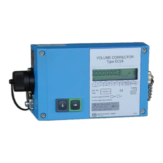
Summary of Contents for RMG EC 24
- Page 1 Reliable Measurement of Gas...
- Page 2 CONTENTS .............................................................................
- Page 3 CONTENTS ......................................................1 ..................1 ......................1 ....................2 ......................2 ......................2 ......................2 ..........................2 ......................... 3 ..............4 ............... 5 ............6 ................8 ..................8 ..............12 ................... 14 ............. 14 ....................... 15 ....................
- Page 4 CONTENTS ....................................................30 ..................31 ......31 ..............33 .................... 34 ............40 ..42 ......................46 ....................52 ....................53 ....................54 ........................................
- Page 5 INTRODUCTION ..............................................................................
- Page 6 INTRODUCTION ............................................................................
- Page 7 INTRODUCTION ..............................................................................
- Page 8 OPERATING MODES ............................................................................
- Page 9 SAFETY INSTRUCTIONS ..............................................................................
- Page 10 SAFETY INSTRUCTIONS ............................................................................
- Page 11 SAFETY INSTRUCTIONS ..............................................................................
- Page 12 INSTALLATION ......................................Pin connector for button on Plug X3 Plug X16_0, service module TERZ94p pressure sensor Plug X2_0 Reset (soldering pads) for TERZ94trm current module and supply Terminals X5 Terminal block X4 Pulse inputs Pulse outputs Plug X6_0 Terminal block X15 EZSENS01 Data interface...
- Page 13 INSTALLATION ..............................................................................
- Page 14 INSTALLATION ......................................Calibration switch Minimum cable cross section: Up to a length of 10 m: 6 mm From a length of 10 m: 10 mm Earthing screw ........................................
- Page 15 INSTALLATION ......................................Cap nut Clamping piece O-ring Connecting piece ........................................
- Page 16 INSTALLATION ............................................................................
- Page 17 INSTALLATION ..............................................................................
- Page 18 OPERATION ............................................................................
- Page 19 OPERATION ..............................................................................
- Page 20 OPERATION ............................................................................
- Page 21 OPERATION ..............................................................................
- Page 22 OPERATION ......................................Flashing character ........................................
- Page 23 OPERATION ......................................3600 3600 3600 B min B max B min B max Pulses Pulses 2362 2362 3600 3600 ........................................
- Page 24 OPERATION ............................................................................
- Page 25 OPERATION ..............................................................................
- Page 26 OPERATION ............................................................................
- Page 27 OPERATION ......................................Note: In the software version 1.0 the user code is not yet implemented. To change parameters with “C” coding it is necessary to open the calibration switch! ........................................
- Page 28 OPERATION ............................................................................
- Page 29 OPERATION ..............................................................................
- Page 30 OPERATION ............................................................................
- Page 31 OPERATION ..............................................................................
- Page 32 OPERATION ............................................................................
- Page 33 OPERATION ..............................................................................
- Page 34 OPERATION ............................................................................
- Page 35 ANNEXES ......................................C(p, T) ........................................
- Page 36 ANNEXES ......................................3600 ........................................
- Page 37 ANNEXES ..............................................................................
- Page 38 ANNEXES ............................................................................
- Page 39 ANNEXES ..............................................................................
- Page 40 ANNEXES ............................................................................
- Page 41 ANNEXES ..............................................................................
- Page 42 ANNEXES ............................................................................
- Page 43 ANNEXES ..............................................................................
- Page 44 ANNEXES ............................................................................
- Page 45 ANNEXES ..............................................................................
- Page 46 ANNEXES ............................................................................
- Page 47 ANNEXES ..............................................................................
- Page 48 ANNEXES ............................................................................
- Page 49 ANNEXES ..............................................................................
- Page 50 ANNEXES ......................................The EC 24 only operates with the following interface parameters ........................................
- Page 51 ANNEXES ......................................Further information you may get from the Modbus specifications.........................................
- Page 52 ANNEXES ............................................................................
- Page 53 ANNEXES ..............................................................................
- Page 54 ANNEXES ............................................................................
- Page 55 ANNEXES ..............................................................................
- Page 56 ANNEXES ............................................................................
- Page 57 ANNEXES ......................................Volume corrector EC 24 Sealing plan with main plate main plate main sealing sealing main plate ........................................
- Page 58 Contact ANNEXES ......................................Subject to technical modification ........................................


Need help?
Do you have a question about the EC 24 and is the answer not in the manual?
Questions and answers