
Subscribe to Our Youtube Channel
Related Manuals for RMG TME 400-VM


Summary of Contents for RMG TME 400-VM
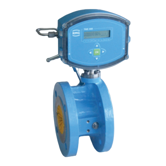
- Page 1 Operating Manual Turbine Meter TME 400-VM (..-VMF) Status: January 22 , 2024 Version: Firmware: 1.12 / 11.12...
- Page 2 Translation of the The manual TME400VMF_manual_en_11 of original document January 22nd, 2024 for the TME 400-VM and TME 400-VMF turbine meters is a translation of the the original German document TME400VMF_manual_de_11.
-
Page 3: Table Of Contents
Contents TABLE OF CONTENTS INTRODUCTION ........................... 1 ........................ 1 TRUCTURE OF THE MANUAL ........................2 URPOSE OF THE MANUAL 1.2.1 Abbreviations ........................2 1.2.2 Symbols ..........................3 1.2.3 Structure of notices ....................... 3 1.2.4 Working with the device ....................... 4 1.2.5 Risk assessment and minimization .................. - Page 4 EADING THE ARCHIVE DATA VIA ODBUS DIMENSIONS ..........................101 MEASURING RANGES FOR TME 400-VMF/ TME 400-VCF ..........106 MEASURING ACCURACY FOR TME 400-VM................107 TYPE PLATE ..........................109 SEAL DIAGRAMS ........................112 LATER INSTALLATION OF THE POWER MODULE ............... 113 SPARE PARTS AND ACCESSORIES ..................
-
Page 5: Introduction
TME 400 is superordinate for both versions of the turbine meter. Note This manual refers to the TME 400-VM and TME 400-VMF instead of the com- plete turbine meter. In addition, the first part includes specifications for the transport and storage of the TME 400. -
Page 6: Purpose Of The Manual
1.2.1 Abbreviations The following abbreviations are used: TME 400-VM The TME 400-VM is a turbine meter which is used for non-cus- tody-transfer volume measurement (Volume Measurement) of the operating volume of non-aggressive gases and combustion fuels is used. TME 400-VMF The TME 400-VMF is a turbine gas meter that is used in custody- transfer applications (Fiscally). -
Page 7: Symbols
1 Introduction MessEG Measurement and Calibration Act Law on the marketing and provision of measuring devices in the market, their use and calibration, valid since 1/1/2015 MessEV Measurement and Calibration Regulation Regulation on the marketing and provision of measuring devices in the market and on their use and calibration;... -
Page 8: Working With The Device
1 Introduction Warning This warning notice informs you of potentially dangerous situations that can arise due to misuse/operator error. If these situations are not avoided, minor injuries can occur. Caution This notice informs you of potentially dangerous situations that can arise due to misuse/operator error. - Page 9 Caution All notices in the manual must be observed. Use of the TME 400 is only per- mitted in accordance with the specifications in the operating manual. RMG assumes no liability for damages arising due to disregard of the operating manual.
- Page 10 1.2.4.2 Dangers during commissioning Initial commissioning The initial commissioning must only be carried out by specially trained personnel (training by RMG) or RMG service personnel. Note An acceptance test certificate must be created during the commissioning. This, the operating manual and the EU Declaration of Conformity must be stored so that they are always readily available.
- Page 11 The descriptions in the operating manual must be observed. In general, it is recommended that the replacement should only be carried out by RMG Service. A leak test must be carried out after work on pressurized components.
- Page 12 1 Introduction 1.2.4.3 Dangers during maintenance and repair Operating personnel The operating personnel use and operate the device in the scope of the intended use. Maintenance personnel Work on the device must only be carried out by qualified personnel who can carry out the respective tasks on the basis of their technical training, experience and familiarity with the applicable standards and requirements.
-
Page 13: Risk Assessment And Minimization
1.2.5 Risk assessment and minimization According to assessment by qualified employees of RMG, the TME 400 is subject to risks during its use. Risks can arise, for example, due to high pressures and occa- sionally due to pressures that are too low. Work outside of the permissible tempera- ture range can also lead to dangers. - Page 14 1 Introduction Non-destructive testing was also carried out: X-ray and ultrasonic inspection of the meter housing for defective points in material, surface crack testing with mag- netic powder and a color penetration process Strength tests for components were conducted at 1.5 times the nominal pressure for the pressure testing;...
- Page 15 1 Introduction Danger The following applies for work in hazardous areas (all zones): The pulse generators of the turbine meter must be connected to intrin- sically safe power circuit only. Only tools that are approved for Ex Zone 1 are permitted for mainte- nance and repair tasks.
-
Page 16: Applicability Of The Manual
This manual describes the TME 400. TME 400 is generally only part of a complete system. The manuals of the other components of the system must be observed. If you find contradictory instructions, contact RMG and/or the manufacturers of the other components. -
Page 17: Transport
1 Introduction 1.2.6.3 Responsibility of the operator As the operator, you must ensure that only adequately qualified personnel work on the device. Ensure that all employees who work with the device have read and un- derstood this manual. You are also obligated to train personnel regularly and inform them of the dangers. -
Page 18: Scope Of Delivery
The scope of delivery can differ depending on the optional orders. The following is "normally” included in the scope of delivery: Part Quan- tity TME 400-VM (or TME 400-VMF) turbine meter 1 Lubricating oil bottle tional Lubricating instructions Manual Manual TME400-VMF · EN11 · January 22nd, 2024... -
Page 19: Storage
Avoid extended periods of storage. After storage, inspect the device for damage and test for correct function. Contact the RMG service department to arrange for inspec- tion of the device after a storage period of longer than one year. For this purpose, re- turn the device to RMG. -
Page 20: Overview Of Versions
1.3.1 Description The TME 400-VM is a turbine meter which is used for volume measurement of the operating volume of non-aggressive gases and burnable gas. The operating volume flow is determined based on the turbine speed, which is scanned by means of a Wie- gand or Reed sensor element and then added together in internal archives. -
Page 21: Firmware
The currently delivered devices have either firmware version 1.12 or 11.12 installed, depending on the components used in the index head. With the devices of the type TME 400-VM(F) there is no functional difference between the two versions. The in- stalled version is shown in coordinate G02. -
Page 22: Area Of Application
1.3.5.1 Installation and mounting position The TME 400-VM and TME 400-VMF can be supplied with DIN and ANSI connec- tions. Up to nominal diameter DN 200, the installation position of the turbine meter with permanent lubrication can be selected as required. From nominal diameter DN 250, the meter must be installed in the ordered installation position. -
Page 23: Use Of Gas Meters For Different Gases
1 Introduction Caution Direct solar radiation must be avoided. Note If different temperature ranges apply simultaneously, the smallest specified range applies for the overall system. This is also marked on the type plate. 1.3.6 Use of gas meters for different gases Symbol Tight- Meter Comments... -
Page 24: Areas Of Application
Not custody transfer measurements are of course possible in natural gases with a hy- drogen content above 10 mol%. However, a reduced measuring range must be taken into account if applicable. Please contact RMG for further information. 1.4 Areas of application The following chapter provides handling instructions for the TME 400 turbine meter for the purpose of safe and reliable operation of the device. -
Page 25: Working Principle Of The Tme 400
1 Introduction 1.4.1 Working principle of the TME 400 The working principle of a mechanical turbine meter is based on the measurement of the gas velocity of the flowing gas which powers a turbine wheel. The speed of the turbine within the measuring range (Q ) is approximately proportional to the mean gas velocity and thus the flow rate. -
Page 26: Integrating The Turbine Meter Into The Pipeline
1.4.2 Integrating the turbine meter into the pipeline Turbine meters from RMG are equipped with connecting flanges. For a secure con- nection, the connection dimensions of the flanges of the pipelines to be connected must match the connection dimensions of the flanges of the device. - Page 27 1 Introduction Flat seals (DIN 2690 / EN 12560-1 Form IBC) PN 10 PN 16 ANSI 150 PN 25 PN 40 2" 3" 4" 6" 8" 10" 12" 16" 20" 24" Grooved seals (EN 12560-6 with centering ring) ANSI 300 / ANSI 600 PN 64 2"...
- Page 28 1 Introduction Spiral seals (EN 12560-2 with centering ring) ANSI 300 PN 64 ANSI 600 2" 69.9 85.9 69.9 85.9 3" 101.6 120.7 101.6 120.7 4" 106.4 127.0 149.4 106.4 120.7 149.4 6" 157.2 182.6 209.6 157.2 174.8 209.6 8" 215.9 233.4 263.7...
- Page 29 1 Introduction Danger Gas escape due to incorrect seal If incorrect flange seals are used for the assembly of turbines, an explosive gas mixture can form due to leaks. Danger of poisoning and explosion! In addition, the stress on the flange is increased to an impermissible level when tightening the thread bolts.
- Page 30 If there is pertubation (e.g. a gas pressure control device) upstream from the inlet pipe, a perforated plate straightener is also necessary. Perforated plate straightener according to ISO 5167-1 or the type RMG LP-35, which cause a pressure loss by a factor of 2.5 in comparison with the standard straightener, can be used.
- Page 31 1 Introduction Perforated plate straightener The opening angle of the reducing or expansion pieces which are installed up- • stream from the TME 400 turbine meter must not be more than 30°. Note If necessary, a screen must be installed before the inlet pipe of the meter for protection of the turbine meter from foreign objects which may be present in the gas flow.
- Page 32 1 Introduction Caution Liquids remaining in the line after hydrostatic testing can damage internal parts of the meter. If hydrostatic testing is not possible, the turbine meter must be replaced with a pipe section. Ensure that there is no liquid remaining in the line above the meter after the hydrostatic testing.
- Page 33 1 Introduction Note The operator should record the overall measurement data (meter and operat- ing data) during the entire operation in order to be able to recognize causes of potential damage at an early stage and to intervene in good time. Remedy and/or relief of critical operating statuses can be achieved, for example, with the following measures: Start-up screen (MW <...
- Page 34 1 Introduction 1.4.2.6 Technical guideline G13 The installation conditions for new systems according to TRG G13 and the facilitated installation conditions for RMG turbine meters are compared in the table below. Type of up- Installation Installation Comments stream per- conditions...
- Page 35 G 13, section 1. The PTB testing vol. 29 and 30, testing of volume gas meters with air at atmospheric pressure and high-pressure testing rules apply as a testing requirement. The RMG turbine meter TME 400 conforms to EN12261. The measuring accuracy in the range of 0.2 Q to Q is between ±...
- Page 36 1 Introduction 1.4.2.8 Measuring ranges Type TME 400 turbine meters have measuring ranges of at least 1:20 at atmospheric pressure (see chapter 1.4.2.9 Measuring accuracy). At a higher pressure, the meas- uring range can be expanded to 1:50. The measuring ranges are between 2.5 and 25,000 m /h (operating conditions), depending on meter size.
- Page 37 1 Introduction According to DIN30690-1, the maximum operating pressure for non-flammable gases may not exceed 16 bar; for flammable gases, EN746-2 defines a maximum pressure of 5 bar for DN25 and 2 bar for DN40. Usually these pressure restrictions are speci- fied on a plate on the pipe fittings.
- Page 38 3150 Perforated plate straightener L2 according to ISO/DIN 6300 Perforated plate straightener L3 according to ISO/DIN 9450 Perforated plate straightener LP-35 RMG standard 1260 Bend straightener RB 19 according to ISO/DIN 1260 The values for Z are rough averages. The exact value is calculated from the pres- sure loss, which is determined when testing the meter.
- Page 39 1 Introduction Example calculation for the pressure loss of a turbine meter: TME 400 in DN 150: = 650 m³/h = 1.3 kg/m³ (natural gas at 600 mbar overpressure) ρ (TME 400) = 5040 (see the table above) Calculation: mbar ∆p 5040 ⋅...
- Page 40 1 Introduction The TME 400 is equipped with permanently lubricated bearings up to a nominal diameter of DN150 as standard. Nominal diameters of DN200 or higher are provided with an integrated lubricating device. Optionally, the TME 400 can also be equipped with the "small oil pump"...
-
Page 41: Installation
2 Installation 2 Installation 2.1 Electrical connections Open the cover of the meter in order to reach the electrical connections. Figure 3: Unscrewing the screws to open the cover Manual TME400-VMF · EN11 · January 22nd, 2024... - Page 42 2 Installation Figure 4: Electronics with cover of the calibration button Jumper for RS 485 terminating resistor. Bridged: with 120 Ω; open: ꝏ Ω Calibration switch Current module board Cover plate for pressure and temperature sensor and calibration switch Normal position, indicated by green arrows Manual TME400-VMF ·...
- Page 43 2 Installation Figure 5: Connection assignment of the TME 400 However, assignments are possible; the pin assignments of the TME 400 are shown in in Figure 5: Connection assignment of the TME 400. If, for example, the TME 400 is to be used as a "flow sensor", the current must be connected to 4..20 mA (termi- nal block X9).
- Page 44 2 Installation Via "+ Uext" (external voltage supply, positive potential) and "- Uext" (external volt- age supply, negative potential) the TME 400 can be fed with 6-30 VDC in addition to the internal battery (in non-Ex areas). "Earth" is used for internal voltage balance. The power supply can be independent or in combination with the RS485 interface.
- Page 45 2 Installation -Pulse 1: HF output negative potential +Pulse 1: HF output positive potential At this output, the arriving pulses at pulse input 1 are synchronously with a pulse width of 1 ms. -Pulse 2: LF output negative potential +Pulse 2: LF output positive potential Output pulses are output at these terminals depending on the change in the volume flow rate.
- Page 46 2 Installation Ex version with modules Phoenix / Turck Manual TME400-VMF · EN11 · January 22nd, 2024...
- Page 47 2 Installation Ex version with modules Pepperl+Fuchs / Turck Manual TME400-VMF · EN11 · January 22nd, 2024...
- Page 48 2 Installation Ex version with modules Phoenix / Omron / Datcom Manual TME400-VMF · EN11 · January 22nd, 2024...
- Page 49 2 Installation Ex version with modules Pepperl+Fuchs / Omron / Datcom Manual TME400-VMF · EN11 · January 22nd, 2024...
- Page 50 2 Installation Ex version with modules Phoenix / Meanwell / Datcom Manual TME400-VMF · EN11 · January 22nd, 2024...
- Page 51 2 Installation Ex version with modules Pepperl+Fuchs / Meanwell / Datcom Manual TME400-VMF · EN11 · January 22nd, 2024...
-
Page 52: Tme 400
3 TME 400 3 TME 400 3.1 Display field A single-line alphanumeric display with 12 characters enables representation of the data and measurements together with the short description or the unit. Total flow volume Figure 6: Display field 8 characters for the value Text: UNIT Unit [m³] Display arrow for volume... -
Page 53: Display Test
3 TME 400 3.1.1 Display test The display test is provided to ensure that all fields of the display function properly. For this purpose, please press and hold the up arrow and down arrow buttons ( ) for more than 2 seconds. The following display appears while these but- tons are held. -
Page 54: Booting Up
3 TME 400 3.1.3 Booting up It may be necessary to re-boot the device in case of severe faults. Caution It is necessary to remove the seals, particularly the seal over the calibration button in order to boot up (see Figure 8: Position of the calibration button). The TME 400 must only be used for custody transfer with unbroken seal. - Page 55 3 TME 400 Note The current parameter settings and meter statuses are lost when re-booting! They are reset to standard values. Therefore, prior to booting up, read and store all parameters of the TME 400. Proceed as follows to re-boot: •...
-
Page 56: Battery Replacement
3 TME 400 3.1.4 Battery replacement Note The coordinate G24 (see chapter 4.3.3.4 Error / type plate) indicates the re- maining battery capacity. If the remaining capacity falls below 10 %, a warn- ing is generated. In order to replace the battery, unscrew the large screw on the right side of the electronics with a large screwdriver or a coin. - Page 57 3 TME 400 Danger The battery must only be replaced in a non-explosive atmosphere. Ensure that the electronics are supplied with adequate ventilation with fresh air. Figure 10: Battery holder Note The battery can be changed during operation. All readings of the counter(s) and all counting parameters are retained. •...
- Page 58 You can also have the battery replaced by the RMG Service department; please contact RMG for this purpose (see page 2). Please only use the battery types intended by RMG. They are available as spare parts. Also observe the information in the Disposal section on page 15.
-
Page 59: Operation
4 Operation 4 Operation 4.1 Operation concept Figure 11: Front panel The concept of the operation is simple and easy to implement with knowledge of the coordinates. 4.1.1 Coordinate system All configuration data, measurements and computed values are sorted in a table in a coordinate system which enables easy access. - Page 60 4 Operation Calc Status Info Figure 12: 8 columns of the coordinate system Note With the TME 400-VM and TME 400-VMF turbine meters, the p/T and Calc. columns cannot be selected. With the cursor buttons (arrows) ◄ ▲ ▼ ►...
-
Page 61: Display And Coordinate System
4 Operation 4.1.2 Display and coordinate system The main meter is displayed in normal operating mode. The other display values can be selected with the operating buttons. After approx. 1 minute, the TME 400 switches back to the main meter. If the display is dark, the TME 400 is in energy-saving mode, where the display is completely switched off. -
Page 62: Programming
Calibration button Custody-transfer variant TME 400-VMF: Custody-transfer display values / parameters, use of the calibration button is necessary. Non-custody-transfer variant TME 400-VM: Entry of the code word is adequate. Note Enabling or disabling the code word or opening the calibration button creates an entry in the event archive (see below). - Page 63 4 Operation Caution It is necessary to remove the seals, particularly the seal over the calibration button in order to press the calibration button (see Figure 8: Position of the calibration button). The TME 400 must only be used for custody transfer with unbroken seal. Re- moval or damage to seals normally entails considerable expenses! Re-application of seals must only be carried out by an officially recognized inspection authority or calibration officials!
- Page 64 4 Operation XVI. After about 1 minute without additional entries, the display returns to the dis- play of the main meter. XVII. By pressing the calibration, you close the further entry of custody-transfer pa- rameters. XVIII. After another minute without an entry, the change possibility is closed auto- matically.
-
Page 65: Equations In The Tme 400
In the following, the coordinates which can be addressed with the TME 400-VM and TME 400-VMF turbine meters are shown. In the tables, the parameters which can be addressed with the TME 400-VM are shown in light blue and the values which are additionally available with the version for custody-transfer applications, TME 400- VMF, are shown in orange. - Page 66 4 Operation 4.3.3.1 Volume / Meters Coordi- Name Description nate Operating volume Volumes added up at current (temperature and pressure) conditions. Uncorrected operating Z26: If the characteristic correction is deactivated, A05 is not visible volume and cannot be adjusted. If a characteristic correction is activated, this characteristic curve correction is deactivated from 0 up to this value A05.
- Page 67 4 Operation Impulse 2362 ⋅ 3600 Impulse ⋅ 2362 3600 If measuring channel-1 or -2 fails, the HF output is switched off. The remaining pulse input is used for further conversion and counting into the disturbed volume counters. (With firmware versions older than 1.11 the High-Frequency (HF) output is switched off if measur- ing channel-1 fails.) Output pulse factor...
- Page 68 4 Operation 99999999 uint32 Volume Start/Stop uint32 99999999 Volume Reset string12 1000.0 Meter factor float 0.01 Output pulse factor menu16 Display factor Digital output 2 pulse menu16 width float Meter factor corrected 4.3.3.2 Flow rate Coordi- Name Description nate Operating flow rate Flow rate under current operating conditions Frequency Unchanged output value, frequency of Sensor 1.
- Page 69 4 Operation Coor- Name Modbus Modbus Protec- Data Min. Max. Default Unit dinate register access tion type Operating flow rate float Frequency float Min. flow rate float Max. flow rate 1000.0 m float Coefficient A-2 float Coefficient A-1 float Coefficient A0 float Coefficient A1 A1x10...
- Page 70 4 Operation Calibration value 4mA Calibration: Current value 4mA (after activation of current source) Calibration value 20mA Calibration: Current value 20mA (after activation of current source) Module serial number Serial number of the current module Coor- Name Modbus Modbus Protec- Data Min.
- Page 71 38400 Bps (default) RS-485 parameter 8N1 (default) RS-485 protocol Modbus RTU (default) Modbus ASCII Modbus ID Modbus device address (default = 1). Modbus register offset The offset is defined as 1 by RMG. Manual TME400-VMF · EN11 · January 22nd, 2024...
- Page 72 4 Operation Coor- Name Modbus Modbus Protec- Data Min. Max. Default Unit dinate register access tion type RS-485 Baud rate menu16 RS-485 parameter menu16 RS-485 protocol menu16 Modbus ID uint16 Modbus register offset 10000 uint16 4.3.3.6 Archive Coordi- Name Description nate Time Direct entry of the current time as described above.
- Page 73 4 Operation X22 delete No (default) X23 fill level Display value All archives Delete all Archives X24 delete No (default) Delete parameter ar- No (default) chive (E) Display value Parameter archive (E) fill level Coor- Name Modbus Modbus Protec- Data Min.
- Page 74 With entry of this code word, the protected parameters can be changed. Change code word A new password can be defined here. Device type TME 400-VM (default) TME 400-VC TME 400-VMF (MID) TME 400-VCF (MID) Display active max. 1 minute (default)
- Page 75 4 Operation With 1-channel measurements (0, 1, 2, 3, 4), the Z04 and Z05 pulse comparison is not activated. An entry for sensor type 2 is superfluous and has no further signifi- cance. Volume metering mode 8: 1 Channel Start/Stop Mode 2 If the external contact input 3 is closed (or opened), this additional mode 2 triggers a start (or stop) for the start/stop totalizer during this time.
- Page 76 4 Operation Coor- Name Modbus Modbus Protec- Data Min. Max. Default Unit dinate register access tion type X:Y maximum pulse error 775 10000 uint16 X:Y maximum pulse 10000 10000 uint16 Error register 1 int16 Error register 2 int16 Status register 1 int16 Status register 2 int16...
-
Page 77: Special Settings
4 Operation 4.4 Special settings 4.4.1 Configuration of the current output The connection of external devices to the current output of the meter is to be carried out as described in chapter 2.1 Electrical connections. The parameters are then set in column 'F Current output' of the coordinate matrix as follows: 1. -
Page 78: Rmgv Iew Tme
4 Operation 4.5 RMGView The RMGView software also provides an additional possibility of parameter input. This software offers you additional options in combination with the TME 400. Figure 13: RMGView software Manual TME400-VMF · EN11 · January 22nd, 2024... -
Page 79: Technical Data
5 Technical data 5 Technical data 5.1.1 Device types Reed or transistor (with connected turbine meter) Pulse input Reed or transistor Current output Current loop connection (current supply via this current output possible) Wiegand (with connected turbine meter) Direct installation on the TME 400 turbine meter instead of the meter head Pulse input Wiegand... -
Page 80: Outputs
5 Technical data 5.1.2.2 Pulse In measuring inputs (sensor 1 / 2) Note For Ex connection values, see approval. 5.1.3 Outputs Non-Ex 30 V 100 mA For use of the TME 400 in hazardous areas the values for the HF, LF and alarm out- put must be taken from the ATEX certificate. -
Page 81: Current Loop Connection
5 Technical data 5.1.5 Current loop connection Current loop connection Uext (min) 12 V Uext (max) 28 V Imin 3.5 mA Imax 23 mA External resistance (max.) See: Figure 14: Load depending on feeder supply Current output for - minimum flow rate 4 mA - maximum flow rate 20 mA... -
Page 82: Cable
5 Technical data 5.1.6 Cable Signal cables (LF output, HF output, current loop connection, control input) must have 2 or more wires twisted in pairs and shielded (LiYCY-TP). 4-wire, twisted and shielded cables (LiYCY-TP) must be used for the data cables (RS-485). - Page 83 5 Technical data Figure 15: Terminal screw connection Coupling nut O-ring Terminal insert Connecting piece Manual TME400-VMF · EN11 · January 22nd, 2024...
-
Page 84: Ground
5 Technical data 5.1.8 Ground Note To avoid measuring errors due to electromagnetic interference, the meter housing must be grounded with the ground connection on the right section of the housing (see Figure 16: Grounding the meter). Minimum cable cross-section: •... - Page 85 5 Technical data Figure 17: Grounding with the connecting pipes Equipotential bonding conductor (PE) min. 6 mm² Measuring system potential Manual TME400-VMF · EN11 · January 22nd, 2024...
-
Page 86: Overview Of Materials In Use
5 Technical data 5.2 Overview of materials in use Name Material Housing Cast iron, cast steel, stainless steel, aluminum or welded steel Flow straightener Delrin, aluminum or steel Turbine wheel Delrin or aluminum Measuring unit Aluminum Ball bearings Stainless steel Shafts Stainless steel Gear wheels... -
Page 87: Error Messages
There are the following error messages: Message Error Brief description Comment type EEprom version error Contact RMG service. EEprom error Contact RMG service. Flow rate min/max error Check the alarm setting for the flow rate. Manual TME400-VMF · EN11 · January 22nd, 2024... - Page 88 Max. output pulse error Check the alarm setting for the max. output pulse. Current output error Check your current connections. Contact RMG service in case of uncertainty. Error CRC Calibration Parameter Contact RMG service. Warning Battery Capacity low Please change the battery...
-
Page 89: Appendix
APPENDIX Appendix Modbus The TME 400 has a passive RS-485 interface, which means the interface must be supplied with power externally. Parameterizing the Modbus Modbus activation H03 RS-485 protocol Modbus RTU (default) Modbus ASCII The Modbus - ID is adjusted via the coordinate H04 (default is 1) The Modbus - Register - Offset (MRO) is entered via coordinate H05 (default is 1). - Page 90 APPENDIX The TME 400 recognizes the following Modbus commands: (03 Hex) Read Holding Registers (06 Hex) Preset Single Register (10 Hex) Preset Multiple Regs (08 Hex) Subfunction 00 Hex: Return Query data TME 400 Exception Codes Illegal Function Illegal Data Address (register not available) Illegal Data Value (register not writable or incorrect value) Example (Modbus query/response): Query:...
- Page 91 APPENDIX Example (Modbus number formats) Data Reg- Value Byte 1 Byte 2 Byte 3 Byte 4 Byte 5 Byte 6 Byte 7 Byte 8 Byte 9 Byte 10 type ister float 0x3f 0x80 0x00 0x00 Text "90111200" 0x39 0x30 0x31 0x31 0x31 0x32...
- Page 92 APPENDIX Modbus - Register (Version:0.001; Matrix: 001; June 2018) Reg. Data Coordinate Name Access Unit Description number type access Volume Mea- Volume at measure- uint32 &VolumeUnit surement ment conditions Volume Mea- Volume at meas. uint32 &VolumeUnit surement Error conditions error Volume Mea- Volume at measure- uint32...
- Page 93 APPENDIX uint16 RW QmMinTime Error curve linearization float Coefficient A-2 coefficent A-2 Error curve linearization float Coefficient A-1 coefficent A-1 Error curve linearization float Coefficient A0 coefficent A0 Error curve linearization float Coefficient A1 coefficent A1 Error curve linearization float Coefficient A2 coefficent A2 float...
- Page 94 APPENDIX Reg. Data Coordinate Name Access Unit Description num- type cess Serial Number Gas 699 2 int32 Serial number gas meter Meter 701 4 string8 Meter size Meter size Date of Battery 705 3 string8 Date of battery exchange Exchange Remaining Battery Remaining Battery Ca- 790 1...
- Page 95 APPENDIX Reg. Data Coordinate Name Access Unit Description number type access Reg. Data Coordinate Name Access Unit Description number type access X:Y maximum Pulse Pulse compare X:Y max- 775 1 uint16 Errors imum pulse errors Pulse compare X:Y max- 776 1 uint16 X:Y maximum Pulses imum pulses...
- Page 96 APPENDIX Error, warning, hint and status registers Reg. Data Description Event number type access number Error: Power-Fail Error: EEprom Error: Pt1000-Hardware Error: Temperature min/max Error: Pressure Sensor-Hardware Error: Pressure min/max uint16 Error: Calculation Gas Equations Error: Flow min/max Error: Pulse Comparison X:Y Error: max.
-
Page 97: Bstructure Of The Archives
APPENDIX Structure of the archives In this appendix you will find more information about the archives: • Archive size • Archive types o Parameter archives o Event archives o Measured values archives • Calculation of the storage size • Archive header •... -
Page 98: B2.1 Parameter Archives
APPENDIX B2.1 Parameter archives The parameter archive contains the history of all parameter changes. The time of the change and the old and the new parameter values are stored in the archive. The parameter archives are divided into one archive each for custody transfer and non-custody transfer parameters. -
Page 99: B2.3 Measured Values Archives
APPENDIX Event type: • High byte: type (‘E‘ = error, ‘W‘ = warning, ‘H‘= note) • Low byte: 0 = Event passes, 1 = Event is coming B2.3 Measured values archives In the measured value archives, meter readings and average values of important measured variables are periodically stored. -
Page 100: B3 Calculation Of The Storage Size
APPENDIX Calculation of the storage size The total available storage for archives is 506880 bytes. Archive type Bytes / Amount Sum in entry entries bytes Parameter archive (custody transfer) 10200 Parameter archive (non-custody transfer) 10200 Event archive 2400 Periodic archive 9000 360000 Daily archive... - Page 101 APPENDIX Empty header ring buffer at the beginning after writing a new entry: Storage index Archive header (Position number 1) -> Actual header empty empty empty Ring buffer after the writing of four entries: Storage index Archive header (Position number 1) Archive header (Position number 2) Archive header (Position number 3) Archive header (Position number 4) ->...
- Page 102 APPENDIX Content of the header after the writing of the second archive entry: Content Data type Value Position number of the next archive UINT16 Index of the oldest entry UINT16 Index of the newest entry UINT16 CRC16 UINT16 xxxxh Content header after the writing of the 300 archive entry (archive full): Content Data type...
-
Page 103: B5 Reading The Archive Data Via Modbus
APPENDIX Reading the archive data via Modbus Archive entries are accessible via Modbus. The command 14h "Read General Ref- erence" is used for this. This command can be used to index the storage ranges of the archives and the corresponding management headers (see document: "Modicon Modbus Protocol;... - Page 104 APPENDIX With the file address the index of the archive to be read is selected. The number of registers of the bytes which are read from an archive entry (number of bytes = number of registers x 2). The maximum number of registers to be read is limited to 125 per request.
-
Page 105: Cdimensions
APPENDIX Dimensions TME 400-VM Front side Rear side Oil pump Top view Top view for flow direction from bottom top up to DN200 Manual TME400-VMF · EN11 · January 22nd, 2024... - Page 106 APPENDIX Dimensions Size Max. Flow rate Weight Qmax Inch m3/h Length L Width B Hight H 1 1/2 1000 1600 1600 2500 2500 PN 10 = 60 4000 PN 25 = 75 4000 PN 25 = 103 6500 PN10 = 86 6500 PN10 = 190 PN16 = 210...
- Page 107 APPENDIX TME 400-VMF Front view Rear side Oil pump Top view Top view for flow direction from bottom top up to DN200 Manual TME400-VMF · EN11 · January 22nd, 2024...
- Page 108 APPENDIX Dimensions Size Max. Flow rate Weight Qmax Inch G-Size m3/h Length L Width B Hight H G100 G160 G250 G160 G250 G400 G400 G650 1000 G1000 1600 G1000 1600 G1600 2500 G1000 1600 ANSI150 = 160 G1600 2500 PN16 = 150 G2500 4000 PN10 = 150...
- Page 109 APPENDIX Remote meter Cable length: 10 m Pressure sensor: integrated in the connection head Height: approx. 80 mm less than the „normal“ height (see above) Manual TME400-VMF · EN11 · January 22nd, 2024...
-
Page 110: Measuring Ranges For Tme 400-Vmf/ Tme 400-Vcf
APPENDIX Measuring ranges for TME 400-VMF/ TME 400-VCF Values for custody transfer metering according to MID approval with natural gas Flow [m³/h] [m³/h] depending on operating pressure p [bar(g)] value [m³/h] [mm] at p =1 bar 1:20 MR 1:30 MR 1:50 MR 1:80 MR 1:100 MR 1:120... -
Page 111: Emeasuring Accuracy For Tme 400-Vm
APPENDIX Measuring accuracy for TME 400-VM Manual TME400-VMF · EN11 · January 22nd, 2024... - Page 112 APPENDIX For TME 400-VMF Manual TME400-VMF · EN11 · January 22nd, 2024...
-
Page 113: Ftype Plate
APPENDIX Type plate Main type plate TME 400-VM for DN25, for Non-Ex, no custody transfer applica- tions Main type plate TME 400-VM from DN40, for Non-Ex, no custody transfer applica- tions Manual TME400-VMF · EN11 · January 22nd, 2024... - Page 114 APPENDIX Main type plate TME 400-VM for DN25, for Ex, no custody transfer applications Main type plate TME 400-VM from DN40, for Ex, no custody transfer applications Manual TME400-VMF · EN11 · January 22nd, 2024...
- Page 115 TÜV 17 ATEX 207566X m³/h T11741 / TC11907 IECEx TUN 18.0009 X =-25°C...+55°C S.-Nr./S.-no. Elektrische Daten siehe EU- Baumusterprüfbescheinigung RMG Messtechnik GmbH Jahr/Year Otto-Hahn-Str. 5 Electrical data see certificate 35510 Butzbach / Germany Type plate for Non-Ex version ...
-
Page 116: Gseal Diagrams
APPENDIX Seal diagrams The following figures show the positions of the seals on the TME 400. Front side Back side In the electronic enclosure At the connection head Manual TME400-VMF · EN11 · January 22nd, 2024... -
Page 117: Hlater Installation Of The Power Module
APPENDIX Later installation of the power module Caution The power module must only be installed in a de-energized state. In order to switch of any power supply the battery must be removed (see chapter 3.1.4 Battery replacement) and any external supply voltage must be switched off, i.e. - Page 118 APPENDIX Putting the power module into operation After reconnecting the TME 400 supply voltages, the current loop power supply must be connected to X9 and the current output parameterized. Caution The voltages of the current loop and the external supply must be electrically isolated (galvanically isolated see chapter 2.1 Electrical connections, espe- cially the connection drawings in the Ex- /Non-Ex area at the end of the chap- ter).
-
Page 119: Ispare Parts And Accessories
APPENDIX Spare parts and accessories Parts of the versions TME 400-VM and TME 400-VC The spare parts marked in red in the following tables are intended exclusively for replacement by RMG service partners! Manual TME400-VMF · EN11 · January 22nd, 2024... - Page 120 APPENDIX Manual TME400-VMF · EN11 · January 22nd, 2024...
- Page 121 APPENDIX Manual TME400-VMF · EN11 · January 22nd, 2024...
- Page 122 APPENDIX Manual TME400-VMF · EN11 · January 22nd, 2024...
- Page 123 APPENDIX Manual TME400-VMF · EN11 · January 22nd, 2024...
- Page 124 APPENDIX Manual TME400-VMF · EN11 · January 22nd, 2024...
- Page 125 APPENDIX Parts of the versions TME 400-VMF and TME 400-VCF The spare parts marked in red in the following tables are intended exclusively for replacement by RMG service partners! Manual TME400-VMF · EN11 · January 22nd, 2024...
- Page 126 APPENDIX Manual TME400-VMF · EN11 · January 22nd, 2024...
- Page 127 APPENDIX Manual TME400-VMF · EN11 · January 22nd, 2024...
- Page 128 APPENDIX Manual TME400-VMF · EN11 · January 22nd, 2024...
- Page 129 APPENDIX Manual TME400-VMF · EN11 · January 22nd, 2024...
- Page 130 APPENDIX Manual TME400-VMF · EN11 · January 22nd, 2024...
- Page 131 APPENDIX Order number Description Expendable materials 92102-00200 Power supply battery 38.11.148.01 Lubricant 2-4°E/20°C TRZ/DKZ 1L 38.11.148.05 Lubricant 2-4°E/20°C TRZ/DKZ 5L Accessories 98800-16590 NonEx TME current module 4-20mA passive 38.02.016.00 EExi supply f.4-20mA current output 86.98.211.01 Power supply 24V/DC 1.4A surface mounted 86.98.249.00 Ex-i power supply 24 V 30.00.619.00...
-
Page 132: Jcertificates And Approvals
The latest version of this manual (and other devices) can be downloaded at your convenience from our Internet page: www.rmg.com. Manual TME400-VMF · EN11 · January 22nd, 2024... - Page 133 APPENDIX Manual TME400-VMF · EN11 · January 22nd, 2024...
- Page 134 APPENDIX Manual TME400-VMF · EN11 · January 22nd, 2024...
- Page 135 APPENDIX Manual TME400-VMF · EN11 · January 22nd, 2024...
- Page 136 APPENDIX Manual TME400-VMF · EN11 · January 22nd, 2024...
- Page 137 APPENDIX Manual TME400-VMF · EN11 · January 22nd, 2024...
- Page 138 APPENDIX Manual TME400-VMF · EN11 · January 22nd, 2024...
- Page 139 APPENDIX Manual TME400-VMF · EN11 · January 22nd, 2024...
- Page 140 APPENDIX Manual TME400-VMF · EN11 · January 22nd, 2024...
- Page 141 APPENDIX Manual TME400-VMF · EN11 · January 22nd, 2024...
- Page 142 APPENDIX Manual TME400-VMF · EN11 · January 22nd, 2024...
- Page 143 APPENDIX Manual TME400-VMF · EN11 · January 22nd, 2024...
- Page 144 APPENDIX Manual TME400-VMF · EN11 · January 22nd, 2024...
- Page 145 APPENDIX Manual TME400-VMF · EN11 · January 22nd, 2024...
- Page 146 APPENDIX Manual TME400-VMF · EN11 · January 22nd, 2024...
- Page 147 APPENDIX Manual TME400-VMF · EN11 · January 22nd, 2024...
- Page 148 APPENDIX Manual TME400-VMF · EN11 · January 22nd, 2024...
- Page 149 APPENDIX Manual TME400-VMF · EN11 · January 22nd, 2024...
- Page 150 APPENDIX Manual TME400-VMF · EN11 · January 22nd, 2024...
- Page 151 APPENDIX Manual TME400-VMF · EN11 · January 22nd, 2024...
- Page 152 APPENDIX Manual TME400-VMF · EN11 · January 22nd, 2024...
- Page 153 APPENDIX Manual TME400-VMF · EN11 · January 22nd, 2024...
- Page 154 Subject to technical changes More information If you would like to learn more about the products and solutions from RMG, visit our website: www.rmg.com or contact your local sales representative RMG Messtechnik GmbH Otto-Hahn-Straße 5 35510 Butzbach, Germany Phone: +49 (0) 6033 897 – 0 Fax: +49 (0) 6033 897 –...
Need help?
Do you have a question about the TME 400-VM and is the answer not in the manual?
Questions and answers