RMG TME400-VCF Operating Manual
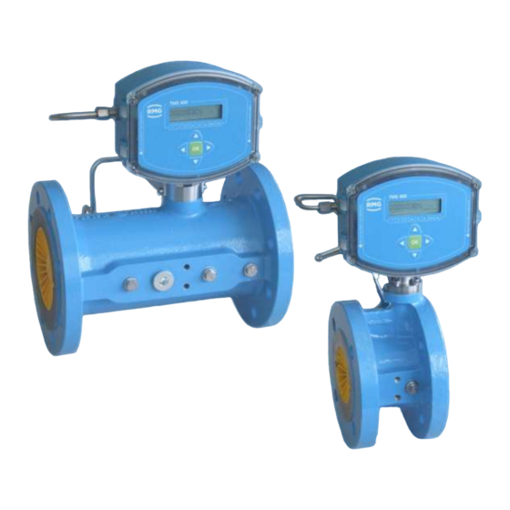
Turbine meter
Hide thumbs
Also See for TME400-VCF:
- Operating manual (98 pages) ,
- Operating manual (156 pages) ,
- Operating manual (154 pages)

Subscribe to Our Youtube Channel
Related Manuals for RMG TME400-VCF


Summary of Contents for RMG TME400-VCF
- Page 1 TME400-VC (..-VCF) turbine meter OPERATING MANUAL Reliable Measurement of Gas Issued: 2019 March 26th Version: Firmware:...
- Page 2 Created June 2018 1. Revision Julye 2018 2. Revision September 2019 February 2019 3. Revision 2019 March 26th 4. Revision Document version and Document TME400VCF_manual_en_04 language version 2019 March 26th Language MANUAL TME400-VCF · EN04 · 2019 March 26th...
-
Page 3: Table Of Contents
USE OF GAS METERS FOR DIFFERENT GASES ............18 1.3.4.3. AREAS OF APPLICATION ...................... 20 1.4. WORKING PRINCIPLE OF THE TME400 ................20 1.4.1. INTEGRATING THE TURBINE METER INTO THE PIPELINE .......... 21 1.4.2. MANUAL TME400-VCF · EN04 · 2019 March 26th... - Page 4 PROGRAMMING WITH THE PROGRAMMING BUTTONS ..........54 4.2.1. EQUATIONS IN THE TME400 ....................57 4.3. VARIABLE DESCRIPTION ....................57 4.3.1. STANDARD FORMULA ....................... 58 4.3.2. COORDINATES IN CONTEXT .................... 58 4.3.3. VOLUME / METERS ......................59 4.3.3.1. MANUAL TME400-VCF · EN04 · 2019 March 26th...
- Page 5 OVERVIEW OF MATERIALS IN USE ..................85 5.2. ERROR MESSAGES ........................86 APPENDIX ............................88 MODBUS ............................88 DIMENSIONS ..........................97 TYPE PLATE ..........................101 SEAL DIAGRAMS ........................103 CERTIFICATES AND APPROVALS..................104 MANUAL TME400-VCF · EN04 · 2019 March 26th...
-
Page 7: Introduction
The differences between the TME400-VC and TME400-VCF turbine meters with volume converters are explained. If there is no ex- plicit reference to differences, the TME400 is superordinate for both versions. -
Page 8: Purpose Of The Manual
(Volume Corrector) from the operating volume flow in non- custody-transfer applications. TME400-VCF The TME400-VCF is used in custody-transfer applications (Fis- cally). In addition to the turbine meter, the TME400-VCF designa- tion also includes the volume corrector. Note This manual only describes the TME400-VC and TME400-VCF. -
Page 9: Symbols
The following notices are used: Danger This warning notice informs you of imminently threatening dangers that can arise due to misuse/operator error. If these situations are not avoided, death or severe injuries can occur. MANUAL TME400-VCF · EN04 · 2019 March 26th... -
Page 10: Working With The Device
Merely following the instructions may not suffice for correct operation. Always remain attentive and consider potential consequences. MANUAL TME400-VCF · EN04 · 2019 March 26th... - Page 11 Caution All notices in the manual must be observed. Use of the TME400 is only per- mitted in accordance with the specifications in the operating manual. RMG assumes no liability for damages arising due to disregard of the operating manual.
-
Page 12: Dangers During Commissioning
Install the device as specified in the operating manual. If the device is not in- stalled as specified in the operating manual, there may be a risk that ade- quate explosion protection is not provided. The explosion protection is lost! MANUAL TME400-VCF · EN04 · 2019 March 26th... - Page 13 Flange fastening elements, fastening screws, screw couplings and check valves, the oil supply, pressure relief connections, valves, HF pulse genera- tors, protective pipes and swivel adapters must not be loosened during oper- ation. MANUAL TME400-VCF · EN04 · 2019 March 26th...
-
Page 14: Dangers During Maintenance And Repair
The TME400 must only be used as intended! (Chapter 1.3Fehler! Verweisquelle konnte nicht gefunden werden.Overview of versions). Prevent use of the TME400 as a potential climbing aid or use of attachments of the TME400 as potential handles! MANUAL TME400-VCF · EN04 · 2019 March 26th... -
Page 15: Qualification Of Personnel
Risk assessment and minimization 1.2.5. According to assessment by qualified employees of RMG, the TME400 is subject to risks during its use. Risks can arise, for example, due to high pressures and occa- sionally due to pressures that are too low. Work outside of the permissible tempera- ture range can also lead to dangers. - Page 16 The risk of ignition due to impact or friction must be avoided. Work on devices which are used in hazardous areas must be carried out by qualified electrical engineers with special capabilities for work in hazardous areas. MANUAL TME400-VCF · EN04 · 2019 March 26th...
-
Page 17: Applicability Of The Manual
This manual describes the TME400. TME400 is generally only part of a complete system. The manuals of the other components of the system must be observed. If you find contradictory instructions, contact RMG and/or the manufacturers of the other components. -
Page 18: Danger During Operation
As the operator, you must ensure that only adequately qualified personnel work on the device. Ensure that all employees who work with the device have read and un- derstood this manual. You are also obligated to train personnel regularly and inform MANUAL TME400-VCF · EN04 · 2019 March 26th... -
Page 19: Transport
Residue from this film changes the flow and causes measuring errors! This protection must be re-applied to the flanges for transport or storage of the device. MANUAL TME400-VCF · EN04 · 2019 March 26th... -
Page 20: Scope Of Delivery
Avoid extended periods of storage. After storage, inspect the device for damage and test for correct function. Contact the RMG service department to arrange for inspec- tion of the device after a storage period of longer than one year. For this purpose, re- turn the device to RMG. -
Page 21: Overview Of Versions
The TME400-VC is used in non-custody-trans- fer applications. The TME400-VCF (MID) is the version of the TME400-VC for custody-transfer ap- plications. The device can be activated via the same outputs. The TME400-VCF (MID) is the turbine meter with volume corrector for custody-trans- fer applications and has an equivalent function and operating method to the TME400- VC. -
Page 22: Power Supply
12 years. If the TME400 is additionally electrical powered by the RS-485 interface, the service life of the battery is typically extended to more than 12 years. MANUAL TME400-VCF · EN04 · 2019 March 26th... -
Page 23: Area Of Application
1.3.4.1. Installation and mounting position The TME400-VC and TME400-VCF can be supplied with DIN and ANSI connections. Up to nominal diameter DN 200, the installation position of the turbine meter with per- manent lubrication can be selected as required. From nominal diameter DN 250, the meter must be installed in the ordered installation position. -
Page 24: Use Of Gas Meters For Different Gases
Use of gas meters for different gases 1.3.4.3. Symbol Tight- Meter Comments ness at housing 0°C and 1.013 bar Natural gas Standard City gas Standard Methane 0.72 Standard Ethane 1.36 Standard MANUAL TME400-VCF · EN04 · 2019 March 26th... - Page 25 2.93 Special The components of the gases must be within the concentration limits according to EN 437:2009 for test gases. Safe operation is guaranteed with these specified gases. Other gases on request. MANUAL TME400-VCF · EN04 · 2019 March 26th...
-
Page 26: Areas Of Application
(Q ) is approximately proportional to the mean gas velocity and thus the flow rate. The number of rotations, therefore, is a measurement for the gas volume flowing through. MANUAL TME400-VCF · EN04 · 2019 March 26th... -
Page 27: Integrating The Turbine Meter Into The Pipeline
Integrating the turbine meter into the pipeline 1.4.2. Turbine meters from RMG are equipped with connecting flanges. For a secure con- nection, the connection dimensions of the flanges of the pipelines to be connected must match the connection dimensions of the flanges of the device. -
Page 28: Seals
Flat seals (DIN 2690 / EN 12560-1 Form IBC) PN 10 PN 16 ANSI 150 PN 25 PN 40 2" 3" 4" 6" 8" 10" 12" 16" 20" 24" Grooved (EN 12560-6 with centering ring) MANUAL TME400-VCF · EN04 · 2019 March 26th... - Page 29 When flange seals which protrude into the pipeline are used for turbine me- ters, the measuring accuracy can be influenced negatively. Ensure that the flange seals do not protrude beyond the seal surfaces into the pipeline. MANUAL TME400-VCF · EN04 · 2019 March 26th...
- Page 30 Ensure secure fastening/attachment of the TME400 during assembly in order to avoid crushing. Ensure that you keep your fingers (or other body parts) away from these openings and gaps when pulling the flanges together. MANUAL TME400-VCF · EN04 · 2019 March 26th...
-
Page 31: Screws
Malfunctions can occur with incorrect seals. Meter housing material 1.4.2.3. Cast steel or round steel material, depending on the pressure level and nominal di- ameter. Aluminum or stainless steel for the screw-type versions. MANUAL TME400-VCF · EN04 · 2019 March 26th... -
Page 32: Installation
If there is pertubation (e.g. a gas pressure control device) upstream from the inlet pipe, a perforated plate straightener is also necessary. Perforated plate straighteners according to ISO 5167-1 or the type RMG LP-35, which cause a pressure loss by a factor of 2.5 in comparison with the standard straightener, can be used. - Page 33 If hydrostatic testing is not possible, the turbine meter must be replaced with a pipe section. Ensure that there is no liquid remaining in the line above the meter after the hydrostatic testing. MANUAL TME400-VCF · EN04 · 2019 March 26th...
-
Page 34: Threshold Values
Start-up screen (MW < 0.15 mm) • Filter • Meter protection perforated plates (Ø 3 - 4 mm) • Valves with control drive (flow change) • Check valves (pulsation, backflow) • MANUAL TME400-VCF · EN04 · 2019 March 26th... -
Page 35: Technical Guideline G13
1 Introduction Technical guideline G13 1.4.2.6. The installation conditions for new systems according to TRG G13 and the facilitated installation conditions for RMG turbine meters are compared in the table below. Type of up- Installation Installation con- Comments stream per-... -
Page 36: Standards / Guidelines
G 13, section 1. The PTB testing vol. 29 and 30, Testing of vol- ume gas meters with air at atmospheric pressure and high-pressure testing rules ap- ply as a testing requirement. The RMG turbine meter TME400 conforms to EN12261. is between 1.0 % to 1.5 % The measuring accuracy in the range of 0.2 Q... -
Page 37: Measuring Ranges
DN25 / thread Rp 1 ISO 7-1 DN40 / thread Pp 1 ½ ISO 7-1 2 – Gas pipe DN25 / thread R1 ISO 7-1 DN40 / thread R1 ½ ISO 7-1 MANUAL TME400-VCF · EN04 · 2019 March 26th... -
Page 38: Measuring Accuracy
80 and 100, which have an increased accuracy with a deviation of max. ±1% in the range of 0.2 x Q 1:20 1000 1:20 1600 1:20 1600 1:20 2500 1:20 2500 1:20 MANUAL TME400-VCF · EN04 · 2019 March 26th... -
Page 39: Pressure Loss
Bend straightener RB 19 according to ISO/DIN 1260 The values for Z are rough averages. The exact value is calculated from the pres- sure loss, which is determined when testing the meter. MANUAL TME400-VCF · EN04 · 2019 March 26th... -
Page 40: Putting The Device Into Operation
Optionally, the TME400 can also be equipped with the "small oil pump" lubricating devices for DN25 to DN150 versions. The type of lubricating device and the lubricant requirement depend on the nominal diameter and the pressure level: MANUAL TME400-VCF · EN04 · 2019 March 26th... - Page 41 (e.g. with continuous condensate formation). Note Recommended lubricating oil: Shell Tellus S2 MA 10 or another oil with 2 to 4°E at 25°C. MANUAL TME400-VCF · EN04 · 2019 March 26th...
-
Page 42: Installation
Open the cover of the meter in order to reach the electrical connections. Figure 3: Unscrewing the screws to open the cover Remove – if necessary – the printed circuit board for sealing of the calibration button. MANUAL TME400-VCF · EN04 · 2019 March 26th... - Page 43 Jumper for RS 485 terminating resistor. Bridged: with 120 ; open: ꝏ Calibration switch Current module board Cover plate for pressure and temperature sensor and calibration switch Normal position, indicated by green arrows MANUAL TME400-VCF · EN04 · 2019 March 26th...
- Page 44 Normally, the resistance is infinitely large (ꝏ ); for a point-to-point con- nection or if the terminal device is part of a bus system, the resistance must be set to 120 . MANUAL TME400-VCF · EN04 · 2019 March 26th...
- Page 45 +Pulse 1: HF output positive potential At this output, the arriving pulses at pulse input 1 are synchronously with a pulse width of 1 ms. -Pulse 2: LF output negative potential +Pulse 2: LF output positive potential MANUAL TME400-VCF · EN04 · 2019 March 26th...
- Page 46 The pulse output factor can be used to weight the number of output pulses in relation to the increase in volume. For the device types TME400-VC and TME400-VCF, the dependence of the pulse output on the standard volume can also be selected (see coordinates A11 and A21).
- Page 47 2 Installation Ex version MANUAL TME400-VCF · EN04 · 2019 March 26th...
- Page 48 2 Installation Ex version with current module MANUAL TME400-VCF · EN04 · 2019 March 26th...
- Page 49 2 Installation Non-Ex version MANUAL TME400-VCF · EN04 · 2019 March 26th...
-
Page 50: Tme400
Display arrow for volume The LCD display and its operation are designed to save energy in order to enable battery-powered operation. The display can be impaired at temperatures below -25°C or above +60°C. MANUAL TME400-VCF · EN04 · 2019 March 26th... -
Page 51: Display Test
The program and operating parameters are not lost in the process and the meter statuses are saved. Booting up 3.1.3. It may be necessary to re-boot the device in case of severe faults. MANUAL TME400-VCF · EN04 · 2019 March 26th... - Page 52 Re-application of seals must only be carried out by an officially recognized inspection authority or calibration officials! Figure 9: Position of the calibration button MANUAL TME400-VCF · EN04 · 2019 March 26th...
- Page 53 Then, re-transmit all device parameters to the TME400 or enter the values from the test certificated. Note The serial interface is set to 38400 Bps, 8N1, Modbus RTU after booting. These are also the default values of RMGView (see chapter 4.4 RMGViewEVC). MANUAL TME400-VCF · EN04 · 2019 March 26th...
-
Page 54: Battery Replacement
When installing the new battery, ensure that the polarity is retained for the new battery. Danger The battery must only be replaced in a non-explosive atmosphere. Ensure that the electronics are supplied with adequate ventilation with fresh air. MANUAL TME400-VCF · EN04 · 2019 March 26th... - Page 55 The current flow rate value is not stored during the change because there is no additional battery buffering. Note You can also have the battery replaced by the RMG Service department; please contact RMG for this purpose (see page 2). Please only use the battery types intended by RMG.
-
Page 56: Operation
All configuration data, measurements and computed values are sorted in a table in a coordinate system which enables easy access. The coordinate system is divided into several columns, as shown on, in part, on the front panel (see top and bottom). MANUAL TME400-VCF · EN04 · 2019 March 26th... - Page 57 The following functions are triggered by pressing: pressed < 2 seconds = display of the coordinate Function pressed > 2 seconds = shows the coordinate pressed > 2 seconds = switch to settings mode (see below) MANUAL TME400-VCF · EN04 · 2019 March 26th...
-
Page 58: Display And Coordinate System
All custody-transfer parameters are protected by the (sealed) calibration but- ton. There are different access authorizations for the parameters with which unauthorized changes are suppressed. The different access rights are assigned to the coordinates MANUAL TME400-VCF · EN04 · 2019 March 26th... - Page 59 Entry of a code word is necessary to change the parameter Calibration button Custody-transfer variant TME400-VCF: Custody-transfer display values / parameters, use of the cal- ibration button is necessary Non-custody-transfer variant TME400-VC: Entry of the code word is adequate MANUAL TME400-VCF · EN04 · 2019 March 26th...
-
Page 60: Programming
Activate the calibration button (see Figure 9: Position of the calibration button) III. The blinking "INPUT" text appears above the displayed value in the display view. Press for more than 2 seconds The value begins to blink at a position MANUAL TME400-VCF · EN04 · 2019 March 26th... - Page 61 After another minute without an entry, the change possibility is closed auto- matically. Note Some of the coordinates permit other settings as purely numerical values. However, these other entries are assigned numbers so that the adjustment can be carried out as described. MANUAL TME400-VCF · EN04 · 2019 March 26th...
- Page 62 Example: Digital output 2 pulse width (coordinate A22) can adjust the pulse width to 3 different widths. The following values can be directly as an assignment: 20 ms 125 ms 250 ms MANUAL TME400-VCF · EN04 · 2019 March 26th...
-
Page 63: Equations In The Tme400
(= 273.15 K) Nondimensional (1) Compressibility coefficient Nondimensional (1) Real gas factor Nondimensional (1) Real gas factor in standard state (calculation for Z and Z takes place according to GERG-88 in accordance with G9) MANUAL TME400-VCF · EN04 · 2019 March 26th... -
Page 64: Standard Formula
In the following, the coordinates which can be addressed with the TME400-VC and TME400-VCF turbine meters are shown. In the tables, the parameters which can be addressed with the TME400-VC are shown in light blue and the values which are ad- ditionally available with the version for custody-transfer applications, TME400-VCF, are shown in orange. -
Page 65: Volume / Meters
K and the minimum and maximum operating volume flow of the meter according to the formula: �� �� �� ������ �� ������ �� ∗ �� �� ∗ �� �� ������ �� �� ������ �� 3600 3600 MANUAL TME400-VCF · EN04 · 2019 March 26th... - Page 66 You get the actual meter status by multiplying the display value by 10. This setting is marked with a "x 10" sticker (or it must be marked). Digital output 2 A21: Digital output 2 mode mode Operating volume (default) Standard volume MANUAL TME400-VCF · EN04 · 2019 March 26th...
-
Page 67: Flow Rate
B14: Factor for the characteristic correction Max. operating point B15: If the deviation of the corrected from the uncorrected character- deviation istic at an operating point (or a range) is more than the adjusted MANUAL TME400-VCF · EN04 · 2019 March 26th... -
Page 68: Pressure
Maximum time > Qug + 10000 unit16 Pressure 4.3.3.3. Coordi- Name Description nate Pressure Currently available pressure Pressure mode Pressure measurement transmitter (source of the pressure measure- ment) Specification (default, fixed value) Wika TI-1 MANUAL TME400-VCF · EN04 · 2019 March 26th... - Page 69 Pressure Minimum float 100.0 float Pressure Maximum 100.0 Pressure offset float -0.5 float Pressure increase Pressure sensor float °C temperature float Min. pressure sensor °C temperature Max. pressure sensor float °C temperature MANUAL TME400-VCF · EN04 · 2019 March 26th...
-
Page 70: Temperature
Only perform this change if you are certain that you have detected a devi- ating temperature measurement. Of course, this correction is subject to the mandatory cali- bration. MANUAL TME400-VCF · EN04 · 2019 March 26th... - Page 71 Correction values displayed in the coordinates D08 (f0) and D09 (f1) are calculated internally. These correction values may only change within the scope of 0.9 to 1.1; otherwise there is a defect which must be corrected by RMG. Coor- Name...
-
Page 72: Analysis
AGA 8 gross method 1 corresponds to GERG 88 S, when the per- centage of H AGA 8 gross method 1 Standard density (Rn), percentage of CO (with percentage of ) = 0) MANUAL TME400-VCF · EN04 · 2019 March 26th... - Page 73 "psi" and "°F" apply. In general, care should be taken, because the pressure / temperature values for the respective standard conditions may deviate from the German standard values. Disregard can result in signification conversion errors. MANUAL TME400-VCF · EN04 · 2019 March 26th...
-
Page 74: Current Outputs
If the current mode is set to "0", i.e. "Off", no parameters of the out- put other than parameter F02: current mode are visible and adjusta- ble. Current source Source of the current output Specification (default) MANUAL TME400-VCF · EN04 · 2019 March 26th... -
Page 75: Error / Type Plate
Error / type plate 4.3.3.7. Coordi- Name Description nate Current error Identifies the current error Software version Shows the version number of the firmware in the TME400. Serial number Serial number of the TME400 MANUAL TME400-VCF · EN04 · 2019 March 26th... - Page 76 Pressure sensor serial string12 number Standard temperature 273.15 TN float Temperature sensor se- 9999 int32 rial number 9999 Meter number 9999 int32 9999 Meter size string8 16000 Batter replacement date 0101 int32 2014 MANUAL TME400-VCF · EN04 · 2019 March 26th...
-
Page 77: Interface
Direct entry of the current time as described above. Date Direct entry of the current date as described above. Delete parameter ar- No (default) chive Param. archive fill level Display value Delete event archive No (default) MANUAL TME400-VCF · EN04 · 2019 March 26th... - Page 78 Default Unit dinate register access tion type Time string8 Date string8 Delete parameter menu16 archive Parameter archive unit16 fill level Delete event menu16 archive Event archive unit16 fill level Measurement archive menu16 mode MANUAL TME400-VCF · EN04 · 2019 March 26th...
-
Page 79: Settings
Display value Error register 2 Display value Status register 1 Display value Status register 2 Display value Code word release Note The code word for the TME400 is: 1 2 3 4 MANUAL TME400-VCF · EN04 · 2019 March 26th... - Page 80 B10 to B14 or can be entered there when the manufacturer of the turbine meter provides these val- ues. Note The HF output pulses (X3 pulse 1) are always uncorrected! MANUAL TME400-VCF · EN04 · 2019 March 26th...
- Page 81 Sensor type 2 menu16 Volume unit menu16 Note If the parameter is not dimensioned, the text in the "Unit" column is shown in the display of the TME400 to the right under UNIT. MANUAL TME400-VCF · EN04 · 2019 March 26th...
-
Page 82: Rmgview Evc
This software offers you additional options in combination with the TME400. Figure 14: RMGView software For further details, please read the corresponding manual, which can be downloaded from our home page (see page 2). MANUAL TME400-VCF · EN04 · 2019 March 26th... -
Page 83: Technical Data
Lithium cell 3.6 V; in the device (battery pack) External 24 V DC via U + battery pack External 10.5 V DC via RS-485 + battery pack External 24 V DC via current loop connection + battery pack MANUAL TME400-VCF · EN04 · 2019 March 26th... -
Page 84: Pulse In Measuring Inputs (Sensor 1 / 2)
• 0.8 bar to 6.0 bar • 2.0 bar to 10.0 bar • 4.0 bar to 20.0 bar Accuracy (at reference conditions according to IEC 61298-1) • ≤ ±0.25 % of span Endress+Hauser Not yet released. MANUAL TME400-VCF · EN04 · 2019 March 26th... -
Page 85: Outputs
In an Ex version, the connection must only be made to a certified, intrinsic safe current circuit. The Ex-relevant connection values are specified in the approval. 5.1.5. Current loop connection Current loop connection (min) 12 V (max) 28 V 3.5 mA 23 mA MANUAL TME400-VCF · EN04 · 2019 March 26th... - Page 86 Current output accuracy better than 1% of the end value Figure 15: Load depending on feeder supply Data for use in Ex areas 28 V 110 mA 770 mW 2.2 LF 110 µH MANUAL TME400-VCF · EN04 · 2019 March 26th...
-
Page 87: Cable
• Plug the terminal insert back into the connecting piece. • Tighten the union nut. • Every Ex signal circuit must be routed with a dedicated cable which must be guided through the appropriate PG screw coupling. MANUAL TME400-VCF · EN04 · 2019 March 26th... - Page 88 5 Technical data Figure 16: Terminal screw connection Coupling nut O-ring Terminal insert Connecting piece MANUAL TME400-VCF · EN04 · 2019 March 26th...
-
Page 89: Ground
• length of 10 m or higher: 10 mm² Figure 17: Grounding the meter In the process, a conductive connection between the TME400 and the pipeline must be provided as shown in the figure below. MANUAL TME400-VCF · EN04 · 2019 March 26th... - Page 90 5 Technical data Figure 18: Grounding with the connecting pipes Equipotential bonding conductor (PE) min. 6 mm² Measuring system potential MANUAL TME400-VCF · EN04 · 2019 March 26th...
-
Page 91: Overview Of Materials In Use
Measuring unit Aluminum Ball bearings Stainless steel Shafts Stainless steel Gear wheels Stainless steel or plastic Magnetic coupling Stainless steel Meter head Plastic Meter printed circuit Aluminum, zinc die-casting or brass board MANUAL TME400-VCF · EN04 · 2019 March 26th... -
Page 92: Error Messages
Pt1000 hardware error Contact RMG service. Temperature min/max error Check the alarm setting for the temperature. Pressure sensor hardware error Contact RMG service. Pressure min/max error Check the alarm setting for the pressure. MANUAL TME400-VCF · EN04 · 2019 March 26th... - Page 93 Check the alarm setting for the pulse comparison. Max. output pulse error Check the alarm setting for the max. output pulse. Current output error Check your power connections. Contact RMG service in case of uncertainty. MANUAL TME400-VCF · EN04 · 2019 March 26th...
-
Page 94: Appendix
Baud rate H01 Baud rate RS-485 interface 2400 Bps 9600 Bps 19200 Bps 38400 Bps (default) Interface parameters The interface parameters can be adjusted in coordinate H02. H02 RS-485 interface parameters 8N1 (default) MANUAL TME400-VCF · EN04 · 2019 March 26th... - Page 95 Slave Address Function Byte Count Data Hi (Reg 2000) see below Data Lo (Reg 2000) see below Data Hi (Reg 2001) see below Data Lo (Reg 2001) see below carriage return line feed MANUAL TME400-VCF · EN04 · 2019 March 26th...
- Page 96 - Deletion of intermediate results (pulse output, meter calculation, etc.). - Therefore, the parameters should only be overwritten as necessary (e.g. meter factor) - Meter statuses are delivered as a unit32 value (without decimal) MANUAL TME400-VCF · EN04 · 2019 March 26th...
- Page 97 RW Meter Factor &CounterFactorUnit Meter factor Output Pulse Output pulse float &CounterFactorUnit Factor factor Meter Factor Meter factor float &CounterFactorUnit corrected corrected menu16 RW Display Factor Display factor MANUAL TME400-VCF · EN04 · 2019 March 26th...
- Page 98 Temperature range pressure 568 2 float °C sensor min. sensor min. Temp. pressure Temperature range pressure 570 2 float °C sensor max. sensor max. Reg. Data Coordinate Name Access Unit Description number type access MANUAL TME400-VCF · EN04 · 2019 March 26th...
- Page 99 Access Unit Description number type access Calculation method for 639 1 menu16 RW Calculation Method compress. Compressibility Deafult value compressi- 640 2 float Default bility 642 2 float Calorific Value Hon Calorific value MANUAL TME400-VCF · EN04 · 2019 March 26th...
- Page 100 Pressure Range min 687 2 float Pressure range maximum Pressure Range max Pressure Sensor Serial number pressure 689 6 string12 R Serial Number sensor Temperature at base con- 695 2 float Temperature Base dition MANUAL TME400-VCF · EN04 · 2019 March 26th...
- Page 101 Fill level day archive 734 1 menu16 RW Delete Month archive Delete month archive 735 1 unit16 Fill level month archive Fill level Month Archive Reg. Data Coordinate Name Access Unit Description number type access MANUAL TME400-VCF · EN04 · 2019 March 26th...
- Page 102 Selection turbine sensor 784 1 menu16 RW Sensor Type 2 channel 2 785 1 menu16 RW Unit Volume Selection volume unit The Modbus access has the meaning: = no protection = calibration button MANUAL TME400-VCF · EN04 · 2019 March 26th...
-
Page 103: Bdimensions
APPENDIX Dimensions TME400-VC Front view Rear side Pressure connection Oil pump Ball valve Top view Temperature connection Top view for flow direction from bottom top up to DN200 MANUAL TME400-VCF · EN04 · 2019 March 26th... - Page 104 1600 ANSI150 = 65 2500 PN10 = 60 4000 PN25 = 71 4000 ANSI150 = 100 6500 PN10 = 90 6500** PN25 = 105 6500 PN16 = 186 10000 PN40 = 275 MANUAL TME400-VCF · EN04 · 2019 March 26th...
- Page 105 APPENDIX TME400-VCF Front view Rear side Pressure test connection Pressure connection Oil pump Three-way test valve Top view Temperature connection Top view for flow direction from bottom top up to DN200 MANUAL TME400-VCF · EN04 · 2019 March 26th...
- Page 106 G1600 2500 G1000 1600 ANSI150 = 160 G1600 2500 PN16 = 150 G2500 4000 PN10 = 150 G2500 4000 ANSI150 = 250 G4000 6500 PN16 = 215 G4000-45 6500** PN10 = 210 MANUAL TME400-VCF · EN04 · 2019 March 26th...
-
Page 107: Ctype Plate
APPENDIX Type plate Main type plate TME400-VC for DN25, for Non-Ex, no custody transfer applica- tions Main type plate TME400-VC from DN40, for Non-Ex, no custody transfer applica- tions MANUAL TME400-VCF · EN04 · 2019 March 26th... - Page 108 APPENDIX Main type plate TME400-VC for DN25, for Ex, no custody transfer applications Main type plate TME400-VC from DN40, for Ex, no custody transfer applications MANUAL TME400-VCF · EN04 · 2019 March 26th...
-
Page 109: Dseal Diagrams
APPENDIX Seal diagrams Will be added as soon as available. MANUAL TME400-VCF · EN04 · 2019 March 26th... -
Page 110: Ecertificates And Approvals
Pressure Equipment Di- rective, which are provided as copies in the appendix. 1. EU Declaration of Conformity 2. ATEX 3. IECEx 4. EU-Type Examination Certificate MANUAL TME400-VCF · EN04 · 2019 March 26th... - Page 111 MANUAL TME400-VCF · EN04 · 2019 March 26th...
- Page 112 Contact Subject to technical changes More information If you would like to learn more about the products and solutions from RMG, visit our website: www.rmg.com or contact your local sales representative RMG Messtechnik GmbH Otto-Hahn-Straße 5 35510 Butzbach, Germany Phone: +49 (0) 6033 897 – 0 Fax: +49 (0) 6033 897 –...
Need help?
Do you have a question about the TME400-VCF and is the answer not in the manual?
Questions and answers