
Related Manuals for RMG TME400


Summary of Contents for RMG TME400
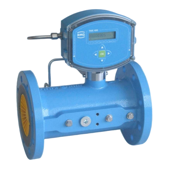
- Page 1 Operating Manual Turbine Meter TME400-VC (..-VCF) Issued: July, 01 2021 Version: Firmware: 1.06...
- Page 2 Translation of the origi- The manual TME400VCF_manual_en_08 of nal document 2021 July 1st for the TME400-VC and TME400-VCF turbine meter with volume convert- ers is the original document. This document is a template for translations in other languages. Note Unfortunately, paper is not updated automatically, whereas technical development continuously ad- vances.
-
Page 3: Table Of Contents
USE OF GAS METERS FOR DIFFERENT GASES ............20 1.3.5.1. SUITABILITY AND SAFETY FOR NATURAL GAS CONTAINING H2 ......21 AREAS OF APPLICATION ...................... 22 1.4. WORKING PRINCIPLE OF THE TME400 ................22 1.4.1. MANUAL TME400-VCF · EN08 · July, 01 2021... - Page 4 PROGRAMMING WITH THE PROGRAMMING BUTTONS ..........58 4.2.1. EQUATIONS IN THE TME400 ....................61 4.3. VARIABLE DESCRIPTION ....................61 4.3.1. STANDARD FORMULA ....................... 62 4.3.2. COORDINATES IN CONTEXT .................... 62 4.3.3. VOLUME / METERS ......................63 4.3.3.1. MANUAL TME400-VCF · EN08 · July, 01 2021...
- Page 5 OVERVIEW OF MATERIALS IN USE ..................91 5.2. ERROR MESSAGES ........................92 APPENDIX ............................94 MODBUS ............................94 STRUCTURE OF THE ARCHIVES ................... 103 RCHIVE SIZE ..........................103 RCHIVE TYPES ..........................103 B2.1 ARAMETER ARCHIVES ......................104 MANUAL TME400-VCF · EN08 · July, 01 2021...
- Page 6 MEASURING RANGES FOR TME 400-VMF/ TME 400-VCF ..........116 TYPE PLATE ..........................117 SEAL DIAGRAMS ........................119 LATER INSTALLATION OF THE POWER MODULE ............. 120 SPARE PARTS AND ACCESSORIES ..................122 CERTIFICATES AND APPROVALS..................123 MANUAL TME400-VCF · EN08 · July, 01 2021...
-
Page 7: Introduction
In addition, the first part includes specifications for the transport and storage of the TME400. The second part of the introduction describes the features and areas of ap- plication of the TME400; basic standards are listed and the pressure and temperature ranges in which the TME400 can and may be used are pre-adjusted. -
Page 8: Purpose Of The Manual
1.2. Purpose of the manual This manual provides information that is necessary for fault-free and safe operation. The TME400 was designed and produced according to the state of the art and gener- ally recognized safety standards and directives. However, its use can entail dangers that are avoidable by complying with this manual. -
Page 9: Symbols
The following notices are used: Danger This warning notice informs you of imminently threatening dangers that can arise due to misuse/operator error. If these situations are not avoided, death or severe injuries can occur. MANUAL TME400-VCF · EN08 · July, 01 2021... -
Page 10: Working With The Device
Merely following the instructions may not suffice for correct operation. Always remain attentive and consider potential consequences. MANUAL TME400-VCF · EN08 · July, 01 2021... - Page 11 Caution All notices in the manual must be observed. Use of the TME400 is only per- mitted in accordance with the specifications in the operating manual. RMG assumes no liability for damages arising due to disregard of the operating manual.
-
Page 12: Dangers During Commissioning
• The technical specifications must be observed and followed for safe operation. Performance limits must not be exceeded (chapter 5 Technical data). • For safe operation, the TME400 must only be used in the scope of the in- tended use (chapter1.3 Overview of versions). -
Page 13: Dangers During Maintenance And Repair
VDE 0105, IEC 364 or comparable standards. Danger Installation and removal of the TME400 must only take place in an explosion- free, pressure-free atmosphere. The descriptions in the operating manual must be observed. In general, it is recommended that the replacement should only be carried out by RMG Service. - Page 14 The TME400 must only be used as intended! (Chapter 1.3 Fehler! Verweis- quelle konnte nicht gefunden werden.Overview of versions). Prevent use of the TME400 as a potential climbing aid or use of attachments of the TME400 as potential handles! MANUAL TME400-VCF · EN08 · July, 01...
-
Page 15: Qualification Of Personnel
Risk assessment and minimization 1.2.5. According to assessment by qualified employees of RMG, the TME400 is subject to risks during its use. Risks can arise, for example, due to high pressures and occa- sionally due to pressures that are too low. Work outside of the permissible tempera- ture range can also lead to dangers. - Page 16 Otherwise, the commissioning inspector must explicitly point out that a test of the equipment location with safety function still has to be performed at the installation site. MANUAL TME400-VCF · EN08 · July, 01 2021...
- Page 17 It is essential that these persons are able to recognize and avoid potential dangers in good time. MANUAL TME400-VCF · EN08 · July, 01 2021...
-
Page 18: Applicability Of The Manual
If you make technical changes to the device, safe operation can no longer be guaran- teed. Danger Only use the device in its original condition. The TME400 is permitted for op- eration in Ex Protection Zone 1, but only within the permissible temperature range (chapter 1.3.4.2 Temperature ranges). -
Page 19: Responsibility Of The Operator
Nevertheless, inform the transport company that all types of impact and vi- brations should be avoided during transport. MANUAL TME400-VCF · EN08 · July, 01 2021... -
Page 20: Scope Of Delivery
The scope of delivery can differ depending on the optional orders. The following is "normally” included in the scope of delivery: Part Quan- tity TME400-VC (or TME400-VCF) turbine meter with integrated elec- tronic volume corrector 1 Lubricating oil bottle tional Lubricating instructions Manual MANUAL TME400-VCF ·... -
Page 21: Disposal Of Packaging Material
Avoid extended periods of storage. After storage, inspect the device for damage and test for correct function. Contact the RMG service department to arrange for inspec- tion of the device after a storage period of longer than one year. For this purpose, re- turn the device to RMG. -
Page 22: Overview Of Versions
Description 1.3.1. The TME400-VC is a turbine meter which is used for volume measurement of the op- erating volume of non-aggressive gases and burnable gas. The operating volume flow is determined based on the turbine speed, which is scanned by means of a Wie- gand or Reed sensor element and then added together. -
Page 23: Power Supply
Archive memory for events, parameters, measurements • TME400-VCF • In addition to the features of the TME400-VC, this version can be used for cus- tody-transfer applications. Power supply 1.3.3. Battery-operated device The TME400 is equipped with a replaceable 3.6 V lithium battery. The device is de- signed for continuous operation for approximately 10 years. -
Page 24: Area Of Application
(see chapter 4.3.3 Coordinates in context). Note In case of a loss of the external power supply, the TME400 is supplied by the buffer battery. The battery symbol is blinking in this case. Area of application 1.3.4. - Page 25 Direct solar radiation must be avoided. Danger The temperature sensor must not be connected via the housing plug on the meter in hazardous areas; a dedicated cable must be routed for the tempera- ture sensor! MANUAL TME400-VCF · EN08 · July, 01 2021...
-
Page 26: Use Of Gas Meters For Different Gases
2.93 Special The components of the gases must be within the concentration limits according to EN 437:2009 for test gases. Safe operation is guaranteed with these specified gases. Other gases on request. MANUAL TME400-VCF · EN08 · July, 01 2021... -
Page 27: Suitability And Safety For Natural Gas Containing H2
1 Introduction 1.3.5.1. Suitability and safety for natural gas containing H2 The TME400 can be used in hydrogen-containing natural gas. There are no safety- related concerns for this use. Notice In accordance with the German TR-G19 – the TME400 is suitable and ap- proved for use in custody transfer applications –... -
Page 28: Areas Of Application
1 Introduction 1.4. Areas of application The following chapter provides handling instructions for the TME400 turbine meter for the purpose of safe and reliable operation of the device. Note Some of the settings described below must not be made until you have read the explanations in chapter4 Operation. - Page 29 (number of pulses per m ). This operating vol- ume is shown in the display of the TME400. MANUAL TME400-VCF · EN08 · July, 01 2021...
-
Page 30: Integrating The Turbine Meter Into The Pipeline
Integrating the turbine meter into the pipeline 1.4.2. Turbine meters from RMG are equipped with connecting flanges. For a secure con- nection, the connection dimensions of the flanges of the pipelines to be connected must match the connection dimensions of the flanges of the device. -
Page 31: Seals
Flat seals (DIN 2690 / EN 12560-1 Form IBC) PN 10 PN 16 ANSI 150 PN 25 PN 40 2" 3" 4" 6" 8" 10" 12" 16" 20" 24" Grooved (EN 12560-6 with centering ring) MANUAL TME400-VCF · EN08 · July, 01 2021... - Page 32 263.7 10" 268,3 287.3 317.5 268,3 274.6 317.5 12" 317,5 339.9 374.7 317,5 327.2 374.7 16" 422.4 463.6 412.8 463.6 20" 525.5 577.9 520.7 577.9 24" 603,3 628.7 685.8 603.3 628.7 685.8 MANUAL TME400-VCF · EN08 · July, 01 2021...
- Page 33 In addition, the stress on the flange is increased to an impermissible level when tightening the thread bolts. Ensure secure fastening/attachment of the TME400 during assembly in order to avoid crushing. Ensure that you keep your fingers (or other body parts) away from these openings and gaps when pulling the flanges together.
-
Page 34: Screws
Malfunctions can occur with incorrect seals. Meter housing material 1.4.2.3. Cast steel or round steel material, depending on the pressure level and nominal di- ameter. Aluminum or stainless steel for the screw-type versions. MANUAL TME400-VCF · EN08 · July, 01 2021... -
Page 35: Installation
(see DVGW guideline G 492 II and PTGB guideline G 13). An inlet pipe of at least 2 x DN is required upstream from the turbine meter TME400. The inlet pipe must be designed as a straight pipe section with the same nominal di- ameter as the meter. - Page 36 If hydrostatic testing is not possible, the turbine meter must be replaced with a pipe section. Ensure that there is no liquid remaining in the line above the meter after the hydrostatic testing. MANUAL TME400-VCF · EN08 · July, 01 2021...
-
Page 37: Threshold Values
Start-up screen (MW < 0.15 mm) • Filter • Meter protection perforated plates (Ø 3 - 4 mm) • Valves with control drive (flow change) • Check valves (pulsation, backflow) • MANUAL TME400-VCF · EN08 · July, 01 2021... -
Page 38: Technical Guideline G13
1 Introduction Technical guideline G13 1.4.2.6. The installation conditions for new systems according to TRG G13 and the facilitated installation conditions for RMG turbine meters are compared in the table below. Type of up- Installation Installation con- Comments stream per-... -
Page 39: Standards / Guidelines
G 13, section 1. The PTB testing vol. 29 and 30, Testing of vol- ume gas meters with air at atmospheric pressure and high-pressure testing rules ap- ply as a testing requirement. The RMG turbine meter TME400 conforms to EN12261. The measuring accuracy in the range of 0.2 Q to Q is between ... -
Page 40: Measuring Ranges
Measuring ranges 1.4.2.8. Type TME400 turbine meters have measuring ranges of at least 1:20 at atmospheric pressure (see chapter 1.4.2.9 Measuring accuracy). At a higher pressure, the meas- uring range can be expanded to 1:50. The measuring ranges are between 2.5 and 25,000 m /h (operating conditions), depending on meter size. -
Page 41: Measuring Accuracy
80 and 100, which have an increased accuracy with a deviation of max. ±1% in the range of 0.2 x Q 1:20 1000 1:20 1600 1:20 1600 1:20 2500 1:20 2500 1:20 MANUAL TME400-VCF · EN08 · July, 01 2021... -
Page 42: Pressure Loss
Bend straightener RB 19 according to ISO/DIN 1260 The values for Z are rough averages. The exact value is calculated from the pres- sure loss, which is determined when testing the meter. MANUAL TME400-VCF · EN08 · July, 01 2021... -
Page 43: Putting The Device Into Operation
Putting the device into operation 1.4.2.11. Note You receive the TME400 parameterized and calibrated according to your specifications, so that no additionally settings are generally required. However, check whether these settings match your specifications; check the settings of the pulse width, the frequency reducer and the settings of the current output (for versions with current output). - Page 44 1 Introduction The TME400 is equipped with permanently lubricated bearings up to a nominal diam- eter of DN150 as standard. Nominal diameter of DN200 or higher are provided with an integrated lubricating device. Optionally, the TME400 can also be equipped with the "small oil pump"...
-
Page 45: Installation
Open the cover of the meter in order to reach the electrical connections. Figure 3: Unscrewing the screws to open the cover Remove – if necessary – the printed circuit board for sealing of the calibration button. MANUAL TME400-VCF · EN08 · July, 01 2021... - Page 46 Jumper for RS 485 terminating resistor. Bridged: with 120 ; open: ꝏ Calibration switch Current module board Cover plate for pressure and temperature sensor and calibration switch Normal position, indicated by green arrows MANUAL TME400-VCF · EN08 · July, 01 2021...
- Page 47 If, for example, the TME400 is to be used as a "flow sensor", the current must be connected to 4..20 mA (terminal block X9). The 4..20 mA current is then connected to the two terminals.
- Page 48 Via "+ Uext" (external voltage supply, positive potential) and "- Uext" (external volt- age supply, negative potential) the TME400 can be fed with 6-30 VDC in addition to the internal battery (in non-Ex areas). "Earth" is used for internal voltage balance.
- Page 49 4: Unscrew the screws to remove the cover and Figure 5: Connection assignment of the TME400; top of the plug strip) in order to open the locking device. Hold down the square and pull the cable out of the connector strip.
- Page 50 2 Installation Ex version MANUAL TME400-VCF · EN08 · July, 01 2021...
- Page 51 2 Installation Ex version with current module MANUAL TME400-VCF · EN08 · July, 01 2021...
- Page 52 2 Installation Non-Ex version MANUAL TME400-VCF · EN08 · July, 01 2021...
-
Page 53: Tme400
Display arrow for volume The LCD display and its operation are designed to save energy in order to enable battery-powered operation. The display can be impaired at temperatures below -25°C or above +60°C. MANUAL TME400-VCF · EN08 · July, 01 2021... -
Page 54: Display Test
Reset 3.1.2. To reset the system, the voltage supply is interrupted and the TME400 is switched off for this period. For this purpose, the battery and any existing external voltage supply are disconnected. The program and operating parameters are not lost in the process and the meter statuses are saved. - Page 55 It is necessary to remove the seals, particularly the seal over the calibration button in order to boot up (see Figure 8: Position of the calibration button). The TME400 must only be used for custody transfer with unbroken seal. Re- moval or damage to seals normally entails considerable expenses!
- Page 56 • Now the device is booted up and the display shows "Boot". • Then, "done" appears in the display and the totalizer status of the main totalizer is displayed. Then, re-transmit all device parameters to the TME400 or enter the values from the test certificated. Note The serial interface is set to 38400 Bps, 8N1, Modbus RTU after booting.
-
Page 57: Battery Replacement
Now, you can pull out the battery holder with battery on a handle. The battery can be removed vertically in relation to the battery holder by pulling slightly. When installing the new battery, ensure that the polarity is retained for the new battery. MANUAL TME400-VCF · EN08 · July, 01 2021... - Page 58 G26 to 0 and the battery capacity G24 to 100 %. The current flow rate value is not stored during the change because • there is no additional battery buffering. MANUAL TME400-VCF · EN08 · July, 01 2021...
- Page 59 You can also have the battery replaced by the RMG Service department; please contact RMG for this purpose (see page 2). Please only use the battery types intended by RMG. They are available as spare parts. MANUAL TME400-VCF · EN08 · July, 01...
-
Page 60: Operation
All configuration data, measurements and computed values are sorted in a table in a coordinate system which enables easy access. The coordinate system is divided into several columns, as shown on, in part, on the front panel (see top and bottom). MANUAL TME400-VCF · EN08 · July, 01 2021... - Page 61 Switches the column of the table from left to right ► Right arrow The following functions are triggered by pressing: pressed < 2 seconds = display of the coordinate Function pressed > 2 seconds = switch to settings mode (see below) MANUAL TME400-VCF · EN08 · July, 01 2021...
-
Page 62: Display And Coordinate System
After approx. 1 minute, the TME400 switches back to the main totalizer. If the display is dark, the TME400 is in energy-saving mode, where the display is completely switched off. The incoming pulses are processed and the outputs are ac- tuated. - Page 63 Non-custody-transfer variant TME400-VC: Entry of the code word is adequate Note Enabling or disabling the code word or opening the calibration button creates an entry in the event archive (see below). MANUAL TME400-VCF · EN08 · July, 01 2021...
-
Page 64: Programming
4 Operation 4.2. Programming There are five buttons available on the front foil for programming of the TME400. Al- ternatively, you can carry out programming via the RMGView operating software (see chapter 4.5 RMGViewTME). Programming with the programming buttons 4.2.1. - Page 65 After another minute without an entry, the change possibility is closed auto- matically. Note Some of the coordinates permit other settings as purely numerical values. However, these other entries are assigned numbers so that the adjustment can be carried out as described. MANUAL TME400-VCF · EN08 · July, 01 2021...
- Page 66 Example: Digital output 2 pulse width (coordinate A22) can adjust the pulse width to 3 different widths. The following values can be directly as an assignment: 20 ms 125 ms 250 ms MANUAL TME400-VCF · EN08 · July, 01 2021...
-
Page 67: Equations In The Tme400
The TME400 enables calculation of different values from the measured data and in the data entered in the TME400. For a better understanding, some variables and for- mula in this chapter are presented in advance; other equations and definitions of pa- rameters are found in the chapter 4.3.3. -
Page 68: Standard Formula
In the following, the coordinates which can be addressed with the TME400-VC and TME400-VCF turbine meters are shown. In the tables, the parameters which can be addressed with the TME400-VC are shown in light blue and the values which are ad- ditionally available with the version for custody-transfer applications, TME400-VCF, are shown in orange. -
Page 69: Volume / Meters
K and the minimum and maximum operating volume flow of the meter according to the formula: �� �� �� ������ �� ������ �� ∗ �� �� ∗ �� �� ������ �� �� ������ �� 3600 3600 MANUAL TME400-VCF · EN08 · July, 01 2021... - Page 70 You get the actual meter status by multiplying the display value by 10. This setting is marked with a "x 10" sticker (or it must be marked). Digital output 2 A21: Digital output 2 mode mode Operating volume (default) Standard volume MANUAL TME400-VCF · EN08 · July, 01 2021...
-
Page 71: Flow Rate
B13: Factor for the characteristic correction B14: Factor for the characteristic correction Max. operating point B15: If the deviation of the corrected from the uncorrected deviation characteristic at an operating point (or a range) is more than MANUAL TME400-VCF · EN08 · July, 01 2021... -
Page 72: Pressure
Maximum time > Qug + 10000 uint16 Pressure 4.3.3.3. Coordi- Name Description nate Pressure Currently available pressure Pressure mode Pressure measurement transmitter (source of the pressure measure- ment) Specification (default, fixed value) Wika TI-1 MANUAL TME400-VCF · EN08 · July, 01 2021... - Page 73 Pressure Minimum float 100.0 Pressure Maximum float 100.0 Pressure offset float -0.5 Pressure increase float Pressure sensor float °C temperature Min. pressure sensor float °C temperature Max. pressure sensor float °C temperature MANUAL TME400-VCF · EN08 · July, 01 2021...
-
Page 74: Temperature
Temperature Minimum This value represents the lowest temperature value of the tempera- ture sensor at which the functionality of the TME400 is still guaran- teed. An error is displayed if the temperature is below this limit. Temperature Maximum This value represents the highest temperature value of the tempera- ture sensor at which the functionality of the TME400 is still guaran- teed. - Page 75 Correction values displayed in the coordinates D08 (f0) and D09 (f1) are calculated internally. These correction values may only change within the scope of 0.9 to 1.1; otherwise there is a defect which must be corrected by RMG. Coor- Name...
-
Page 76: Analysis
Compression factor Compressibility (from AGA8, etc.); see above. Calculation method The TME400 enables calculation of gas parameters, particularly the compression factor according to various methods. These methods must be adjusted in coordinate E05 with the corresponding number. Available for selection:... - Page 77 25°C applies as a standard combustion temperature for determining the calorific value (E22). Selection of standard pressure 1.01325 bar (default) 1.0 bar Standard temperature Selection of standard temperature selection 0° C (default) MANUAL TME400-VCF · EN08 · July, 01 2021...
- Page 78 100.0 Relative density float 100.0 25.0 Fraction of carbon dioxide float 100.0 Nitrogen float 100.0 25.0 Hydrogen float 100.0 Selection standard menü16 pressure Selection standard menü16 temperature Selection combustion menü16 temperature MANUAL TME400-VCF · EN08 · July, 01 2021...
-
Page 79: Current Output
Module serial number Serial number of the current module Coor- Name Modbus Modbus Protec- Data Min. Max. Default Unit dinate register access tion type Current float Current mode menü16 Current source menü16 MANUAL TME400-VCF · EN08 · July, 01 2021... -
Page 80: Error / Type Plate
Description nate Current error Identifies the current error Software version Shows the version number of the firmware in the TME400. Serial number Serial number of the TME400 Firmware checksum Shows the checksum of the firmware (important for TME400-VMF and TME400-VCF in custody-transfer applications) -
Page 81: Interface
Meter size string8 4-16000 Batter replacement date 0101 int32 2014 4.3.3.8. RS-485 interface Coordi- Name Description nate RS-485 Baud rate 2400 Bps 9600 Bps 19200 Bps 38400 Bps (default) RS-485 parameter 8N1 (default) MANUAL TME400-VCF · EN08 · July, 01 2021... -
Page 82: Archive
4 Operation RS-485 protocol Modbus RTU (default) Modbus ASCII Modbus ID Modbus device address (default = 1). Modbus register offset The offset is defined as 1 by RMG. Coor- Name Modbus Modbus Protec- Data Min. Max. Default Unit dinate register... - Page 83 Delete minute archive menu16 Minute archive fill level uint16 Delete day archive menu16 Day archive fill level uint16 Delete month archive menu16 Month archive fill level uint16 Delete all archives menu16 MANUAL TME400-VCF · EN08 · July, 01 2021...
-
Page 84: Settings
Display value Code word release Note The code word for the TME400 is: 1 2 3 4 This is always displayed as " **** " in the parameter archive. With entry of this code word, the protected parameters can be changed. - Page 85 In case of an error, the pulses are counted in the error totalizers and current and pulses are output. Characteristic correc- If the TME400 is supplied with a current supply, the TME400 ena- tion bles a characteristic correction via a polynomial. This correction must be activated with coordinate Z26.
- Page 86 Sensor type 2 menu16 Volume unit menu16 Note If the parameter is not dimensioned, the text in the "Unit" column is shown in the display of the TME400 to the right under UNIT. MANUAL TME400-VCF · EN08 · July, 01 2021...
-
Page 87: Special Settings
5. In F-06 (current specification) a fixed value can be entered for the current which is output with the entry 0 in coordinate F-02. 6. In F-07 (damping) the inertia oft he output can be set with values from 0 (mini- mum) to 0.99 (maximum). MANUAL TME400-VCF · EN08 · July, 01 2021... -
Page 88: Rmgview Tme
4.5. RMGView The RMGView software also provides an additional possibility of parameter input. This software offers you additional options in combination with the TME400. Figure 13: RMGView software For further details, please read the corresponding manual, which can be downloaded from our home page (see page 2). -
Page 89: Technical Data
Reed or transistor Current output Current loop connection (current supply via this current output possible) Wiegand (with connected turbine meter) Direct installation on the TME400 turbine meter instead of the meter head Pulse input Wiegand Current output Current loop connection... -
Page 90: Pulse In Measuring Inputs (Sensor 1 / 2)
• 0.8 bar to 6.0 bar • 2.0 bar to 10.0 bar • 4.0 bar to 20.0 bar Accuracy (at reference conditions according to IEC 61298-1) • ≤ ±0.25 % of span Endress+Hauser Not yet released. MANUAL TME400-VCF · EN08 · July, 01 2021... -
Page 91: Outputs
Outputs 5.1.3. Non-Ex 30 V 100 mA For use of the TME400 in hazardous areas the values for the HF, LF and alarm out- put must be taken from the ATEX certificate. 5.1.4. Digital interface RS-485 data interface 6.0 – 24 V For use of the TME400 in hazardous areas the values must be taken from the ATEX certificate. - Page 92 Current output accuracy better than 1% of the end value Figure 14: Load depending on feeder supply For use of the TME400 in hazardous areas the values must be taken from the ATEX certificate. MANUAL TME400-VCF · EN08 · July, 01...
-
Page 93: Cable
4-wire, twisted and shielded cables (LiYCY-TP) must be used for the data cables (RS-485). The shielding must be grounded on both ends - on the TME400, as described in the section 5.1.7. Cable connection. Cable cross-sections of 0.5 mm² are recommended. Due to the cable screw connec- tion, the outer diameter of the cable must be between 4.5 and 6.5 mm. - Page 94 5 Technical data Figure 15: Terminal screw connection Coupling nut O-ring Terminal insert Connecting piece MANUAL TME400-VCF · EN08 · July, 01 2021...
-
Page 95: Ground
• length of 10 m or higher: 10 mm² Figure 16: Grounding the meter In the process, a conductive connection between the TME400 and the pipeline must be provided as shown in the figure below. MANUAL TME400-VCF · EN08 · July, 01... - Page 96 5 Technical data Figure 17: Grounding with the connecting pipes Equipotential bonding conductor (PE) min. 6 mm² Measuring system potential MANUAL TME400-VCF · EN08 · July, 01 2021...
-
Page 97: Overview Of Materials In Use
Measuring unit Aluminum Ball bearings Stainless steel Shafts Stainless steel Gear wheels Stainless steel or plastic Magnetic coupling Stainless steel Meter head Plastic Meter printed circuit Aluminum, zinc die-casting or brass board MANUAL TME400-VCF · EN08 · July, 01 2021... -
Page 98: Error Messages
H = Hint There are the following error messages: Mes- Error Brief description Comment sage type EEprom version error Contact RMG service. EEprom error Contact RMG service. Pt1000 hardware error Contact RMG service. MANUAL TME400-VCF · EN08 · July, 01 2021... - Page 99 Contact RMG service. Warning Battery Capacity low Please change the battery New software version You have a new firmware version Metrology switch open Metrology switch open Code word set Code word is set MANUAL TME400-VCF · EN08 · July, 01 2021...
-
Page 100: Appendix
APPENDIX Appendix Modbus The TME400 has a passive RS-485 interface, which means the interface must be supplied with power externally. Parameterizing the Modbus Modbus activation H03 RS-485 protocol Modbus RTU (default) Modbus ASCII The Modbus - ID is adjusted via the coordinate H04 (default is 1) The Modbus - Register - Offset (MRO) is entered via coordinate H05 (default is 1). - Page 101 APPENDIX The TME400 recognizes the following Modbus commands: (03 Hex) Read Holding Registers (06 Hex) Preset Single Register (10 Hex) Preset Multiple Regs (08 Hex) Subfunction 00 Hex: Return Query data TME400 Exception Codes Illegal Function Illegal Data Address (register not available)
- Page 102 - Deletion of intermediate results (pulse output, meter calculation, etc.). - Therefore, the parameters should only be overwritten as necessary (e.g. meter factor) - Meter statuses are delivered as a uint32 value (without decimal) MANUAL TME400-VCF · EN08 · July, 01 2021...
- Page 103 RW Meter Factor &CounterFactorUnit Meter factor Output Pulse Output pulse float &CounterFactorUnit Factor factor Meter Factor Meter factor float &CounterFactorUnit corrected corrected menu16 RW Display Factor Display factor MANUAL TME400-VCF · EN08 · July, 01 2021...
- Page 104 Temperature range pressure 568 2 float °C sensor min. sensor min. Temp. pressure Temperature range pressure 570 2 float °C sensor max. sensor max. Reg. Data Coordinate Name Access Unit Description number type access MANUAL TME400-VCF · EN08 · July, 01 2021...
- Page 105 Calculation method for 639 1 menu16 RW Calculation Method compress. Default Default value for the 640 2 float Compression factor compression factor 642 2 float Calorific Value Hon Calorific value MANUAL TME400-VCF · EN08 · July, 01 2021...
- Page 106 Pressure at base condition 685 2 float Pressure range minimum Pressure Range min 687 2 float Pressure range maximum Pressure Range max Pressure Sensor Serial number pressure 689 6 string12 R Serial Number sensor MANUAL TME400-VCF · EN08 · July, 01 2021...
- Page 107 729 1 menu16 RW Interval Minute Archive E Interval minute archiv 730 1 menu16 RW Delete Minute Archive Delete minute archive 731 1 uint16 Fill level minute archive Fill level Minute Archive MANUAL TME400-VCF · EN08 · July, 01 2021...
- Page 108 Selection turbine sensor 784 1 menu16 RW Sensor Type 2 channel 2 785 1 menu16 RW Unit Volume Selection volume unit The Modbus access has the meaning: = no protection = calibration button MANUAL TME400-VCF · EN08 · July, 01 2021...
-
Page 109: Bstructure Of The Archives
• Calculation of the storage size • Archive header • Reading the archive data via Modbus Archive size The TME400 has an archive storage divided into the following archive types with the given archive sizes: Event archive 200 Entries Parameter archive (custody transfer) -
Page 110: B2.2 Event Archives
TME400. Internal structure of an entry: Content Data type Length in Bytes Position number UINT16 Unix time (device time) UINT32 Event type UINT16 Event number UINT16 CRC16 (Modbus) UINT16 Total length: 12 MANUAL TME400-VCF · EN08 · July, 01 2021... -
Page 111: B2.3 Measured Values Archives
Operating volume UINT32 Standard volume Error UINT32 Operating volume Error UINT32 Exponent (to base 10) INT16 Mean pressure FLOAT Mean temperature FLOAT Mean compressibility FLOAT Status UINT16 CRC16 (Modbus) UINT16 Total length: 40 MANUAL TME400-VCF · EN08 · July, 01 2021... -
Page 112: B3 Calculation Of The Storage Size
This is to ensure that the information is stored safely in case of cell defects in the EEprom. Each time a new archive entry is written, the corresponding archive header is updated and stored as the next entry in the ring buffer: MANUAL TME400-VCF · EN08 · July, 01 2021... - Page 113 Content of the header after the writing of the first archive entry: Inhalt Data type Value Position number of the next archive UINT16 Index of the oldest entry UINT16 Index of the newest entry UINT16 CRC16 UINT16 xxxxh MANUAL TME400-VCF · EN08 · July, 01 2021...
- Page 114 No. of ent. = max. archive ent. - "Index older ent." + "Index newest ent." + 1 (Archive is always full: Number of entries = Maximum archive entries, Calculation for the purpose of completeness only) MANUAL TME400-VCF · EN08 · July, 01 2021...
-
Page 115: B5 Reading The Archive Data Via Modbus
Number of registers to be read (Lo) CRC (Lo) CRC (Hi) The specified reference type in the request string is not checked in the TME400. The following file number selects the archive or archive header to be read: File number... - Page 116 (index 7 and 8) and a part archive (2 bytes from index 9). In practice, it makes sense to request only complete archives. The above case is used exclusively to il- lustrate the mechanism. MANUAL TME400-VCF · EN08 · July, 01 2021...
-
Page 117: Cdimensions
APPENDIX Dimensions TME400-VC Front view Rear side Pressure connection Oil pump Ball valve Top view Temperature connection Top view for flow direction from bottom top up to DN200 MANUAL TME400-VCF · EN08 · July, 01 2021... - Page 118 1600 ANSI150 = 65 2500 PN10 = 60 4000 PN25 = 71 4000 ANSI150 = 100 6500 PN10 = 90 6500** PN25 = 105 6500 PN16 = 186 10000 PN40 = 275 MANUAL TME400-VCF · EN08 · July, 01 2021...
- Page 119 APPENDIX TME400-VCF Front view Rear side Pressure test connection Pressure connection Oil pump Three-way test valve Top view Temperature connection Top view for flow direction from bottom top up to DN200 MANUAL TME400-VCF · EN08 · July, 01 2021...
- Page 120 G1600 2500 G1000 1600 ANSI150 = 160 G1600 2500 PN16 = 150 G2500 4000 PN10 = 150 G2500 4000 ANSI150 = 250 G4000 6500 PN16 = 215 G4000-45 6500** PN10 = 210 MANUAL TME400-VCF · EN08 · July, 01 2021...
- Page 121 APPENDIX Remote meter Cable length: 10 m Pressure sensor: integrated in the connection head Height: approx. 80 mm less than the „normal“ height (see above) MANUAL TME400-VCF · EN08 · July, 01 2021...
-
Page 122: Measuring Ranges For Tme 400-Vmf/ Tme 400-Vcf
1600 2500 2500 4000 2500 4000 4000 6500 1300 4000-45 6500 1300 p = 1 bar; means atmospheric pressure MR = Measuring range = Q MR: 1:20; for p ≥ 3 bar(g) MANUAL TME400-VCF · EN08 · July, 01 2021... -
Page 123: Etype Plate
APPENDIX Type plate Main type plate TME400-VC for DN25, for Non-Ex, no custody transfer applica- tions Main type plate TME400-VC from DN40, for Non-Ex, no custody transfer applica- tions MANUAL TME400-VCF · EN08 · July, 01 2021... - Page 124 APPENDIX Main type plate TME400-VC for DN25, for Ex, no custody transfer applications Main type plate TME400-VC from DN40, for Ex, no custody transfer applications MANUAL TME400-VCF · EN08 · July, 01 2021...
-
Page 125: Fseal Diagrams
APPENDIX Seal diagrams The following figures show the positions of the seals on the TME400. Front side Back side In the electronic enclosure At the connection head MANUAL TME400-VCF · EN08 · July, 01 2021... -
Page 126: Glater Installation Of The Power Module
Figure 1: Electronic with power module Jumper for RS 485 terminating resistor. Bridged: with 120 ; open: ꝏ Calibration switch Current module board Cover plate for pressure and temperature sensor and calibration switch MANUAL TME400-VCF · EN08 · July, 01 2021... - Page 127 APPENDIX Normal position, indicated by green arrows Putting the power module into operation After reconnecting the TME400 supply voltages, the current loop power supply must be connected to X9 and the current output parameterized. Caution The voltages of the current loop and the external supply must be electrically isolated (galvanically isolated see chapter 2.1 Electrical connections , espe-...
-
Page 128: Hspare Parts And Accessories
Interface/pulse separating module Datcom K3 35.00.000.00 PS (230V/AC - 12V/DC) for K3 module 86.76.553.00 OMRON DC/DC adapter for Datcom K3 Expendable materials 92102-00200 Power supply battery 38.11.148.01 Lubricant 2-4°E/20°C TRZ/DKZ 1L 38.11.148.05 Lubricant 2-4°E/20°C TRZ/DKZ 5L MANUAL TME400-VCF · EN08 · July, 01 2021... -
Page 129: Certificates And Approvals
APPENDIX Certificates and approvals The TME400 is approved for custody-transfer measurements. Approvals are avail- able for operation in hazardous environments and for the Pressure Equipment Di- rective, which are provided as copies in the appendix. 1. EU Declaration of Conformity 2. - Page 130 APPENDIX MANUAL TME400-VCF · EN08 · July, 01 2021...
- Page 131 APPENDIX MANUAL TME400-VCF · EN08 · July, 01 2021...
- Page 132 APPENDIX MANUAL TME400-VCF · EN08 · July, 01 2021...
- Page 133 APPENDIX MANUAL TME400-VCF · EN08 · July, 01 2021...
- Page 134 APPENDIX MANUAL TME400-VCF · EN08 · July, 01 2021...
- Page 135 APPENDIX MANUAL TME400-VCF · EN08 · July, 01 2021...
- Page 136 APPENDIX MANUAL TME400-VCF · EN08 · July, 01 2021...
- Page 137 APPENDIX MANUAL TME400-VCF · EN08 · July, 01 2021...
- Page 138 APPENDIX MANUAL TME400-VCF · EN08 · July, 01 2021...
- Page 139 APPENDIX MANUAL TME400-VCF · EN08 · July, 01 2021...
- Page 140 APPENDIX MANUAL TME400-VCF · EN08 · July, 01 2021...
- Page 141 APPENDIX MANUAL TME400-VCF · EN08 · July, 01 2021...
- Page 142 APPENDIX MANUAL TME400-VCF · EN08 · July, 01 2021...
- Page 143 APPENDIX MANUAL TME400-VCF · EN08 · July, 01 2021...
- Page 144 APPENDIX MANUAL TME400-VCF · EN08 · July, 01 2021...
- Page 145 APPENDIX MANUAL TME400-VCF · EN08 · July, 01 2021...
- Page 146 APPENDIX MANUAL TME400-VCF · EN08 · July, 01 2021...
- Page 147 APPENDIX MANUAL TME400-VCF · EN08 · July, 01 2021...
- Page 148 APPENDIX MANUAL TME400-VCF · EN08 · July, 01 2021...
- Page 149 APPENDIX MANUAL TME400-VCF · EN08 · July, 01 2021...
- Page 150 APPENDIX MANUAL TME400-VCF · EN08 · July, 01 2021...
- Page 151 APPENDIX MANUAL TME400-VCF · EN08 · July, 01 2021...
- Page 152 APPENDIX MANUAL TME400-VCF · EN08 · July, 01 2021...
- Page 153 APPENDIX MANUAL TME400-VCF · EN08 · July, 01 2021...
- Page 154 APPENDIX MANUAL TME400-VCF · EN08 · July, 01 2021...
- Page 155 MANUAL TME400-VCF · EN08 · July, 01 2021...
- Page 156 RMG Messtechnik GmbH Otto-Hahn-Straße 5 35510 Butzbach, Germany Phone: +49 (0) 6033 897 – 0 Fax: +49 (0) 6033 897 – 130 Email: service@rmg.com MANUAL TME400-VCF · EN08 · July, 01 2021...
Need help?
Do you have a question about the TME400 and is the answer not in the manual?
Questions and answers